


Data sheet
Cisco public
Cisco Catalyst 1000
Series Switches
© 2020 Cisco and/or its affiliates. All rights reserved. |
Page 1 of 21 |

Contents
Product overview |
3 |
Product highlights |
3 |
Switch models and configurations |
3 |
Network management |
6 |
Intelligent PoE+ |
6 |
Specifications |
10 |
Warranty |
17 |
Cisco environmental sustainability |
17 |
Software policy |
18 |
Technical support and services |
18 |
Accessories |
19 |
Ordering information |
19 |
Cisco Capital |
21 |
Contact Cisco |
21 |
© 2020 Cisco and/or its affiliates. All rights reserved. |
Page 2 of 21 |

Product overview
Cisco® Catalyst® 1000 Series Switches are fixed managed Gigabit Ethernet enterprise-class Layer 2 switches designed for small businesses and branch offices. These are simple, flexible and secure switches ideal for out-of-the-wiring-closet and critical Internet of Things (IoT) deployments. Cisco® Catalyst® 1000 operate on Cisco IOS® Software and support simple device management and network management via a Command-Line Interface (CLI) as well as an on-box web UI. These switches deliver enhanced network security, network reliability, and operational efficiency for small organizations.
Product highlights
Cisco Catalyst 1000 Series Switches feature:
●8, 16, 24, or 48 Gigabit Ethernet data or PoE+ ports with line-rate forwarding
●2 or 4 fixed 1 Gigabit Ethernet Small Form-Factor Pluggable (SFP)/RJ 45 Combo uplinks or 4 fixed 0 Gigabit Ethernet Enhanced SFP (SFP+) uplinks
●Perpetual PoE+ support with a power budget of up to 740W
●CLI and/or intuitive web UI manageability options
●Network monitoring through sampled flow (sFlow)
●Security with 802.1X support for connected devices, Switched Port Analyzer (SPAN), and Bridge Protocol Data Unit (BPDU) Guard
●Compact fanless models available with a depth of less than 13 inches (33 cm)
●Device management support with over-the-air access via Bluetooth, Simple Network Management Protocol (SNMP), RJ-45, or USB console acces
●Reliability with a higher Mean Time Between Failures (MTBF) and an enhanced limited lifetime warranty support(E-LLW)
Switch models and configurations
Cisco Catalyst 1000 Series Switches include a single fixed power supply. Table 1 shows configuration information.
Table 1. Switch configurations
Product ID* |
Gigabit |
Uplink |
PoE+power |
Fanless |
Dimensions (WxDxH |
Weight (kg) |
|
|
Ethernet ports |
interfaces |
budget |
|
in inches) |
|
|
|
|
|
|
|
|
|
|
C1000-8T-2G-L |
8 |
2 SFP/ RJ-45 |
– |
Y |
10.56 x 7.28 x 1.73 |
1.80 |
|
|
|
combo |
|
|
|
|
|
|
|
|
|
|
|
|
|
C1000-8T-E-2G-L |
8 |
2 SFP/ RJ-45 |
– |
Y |
10.56 x 7.28 x 1.73 |
1.55 |
|
|
|
combo |
|
|
|
|
|
|
|
|
|
|
|
||
|
|
|
|
|
|
|
|
C1000-8P-2G-L |
8 |
2 SFP/ RJ-45 |
67W |
Y |
10.56 x 12.73 x 1.73 |
1.55 |
|
|
|
combo |
|
|
|
|
|
|
|
|
|
|
|
|
|
C1000-8P-E-2G-L |
8 |
2 SFP/ RJ-45 |
67W |
Y |
10.56 x 7.28 x 1.73 |
1.55 |
|
|
|
combo |
|
|
|
|
|
|
|
|
|
|
|
||
|
|
|
|
|
|
|
|
© 2020 Cisco and/or its affiliates. All rights reserved. |
|
|
|
|
Page 3 of 21 |
||
|
|
|
|
|
|
|
|
|
|
|
|
|
|
|
|
|
|
|
Product ID* |
Gigabit |
Uplink |
PoE+power |
Fanless |
Dimensions (WxDxH |
Weight (kg) |
|
|
|
Ethernet ports |
interfaces |
budget |
|
in inches) |
|
|
|
|
|
|
|||||
|
|
|
|
|
|
|
|
|
|
C1000-8FP-2G-L |
8 |
2 |
SFP/ RJ-45 |
120W |
Y |
10.56 x 12.73 x 1.73 |
2.70 |
|
|
|
combo |
|
|
|
|
|
|
|
|
|
|
|
|
|
|
|
C1000-8FP-E-2G-L |
8 |
2 |
SFP/ RJ-45 |
120W |
Y |
10.56 x 7.28 x 1.73 |
2.70 |
|
|
|
combo |
|
|
|
|
|
|
|
|
|
|
|
|
||
|
|
|
|
|
|
|
|
|
|
C1000-16T-2G-L |
16 |
2 |
SFP |
– |
Y |
10.56 x 10.69 x 1.73 |
1.78 |
|
|
|
|
|
|
|
|
|
|
C1000-16T-E-2G-L |
16 |
2 |
SFP |
- |
Y |
10.56 x 8.26 x 1.73 |
1.42 |
|
|
|
|
|
|
|
|
|
|
C1000-16P-2G-L |
16 |
2 |
SFP |
120W |
Y |
10.56 x 11.69 x 1.73 |
2.38 |
|
|
|
|
|
|
|
|
|
|
C1000-16P-E-2G-L |
16 |
2 |
SFP |
120W |
Y |
10.56 x 8.26x 1.73 |
1.42 |
|
|
|
|
|
|
|
|
|
|
C1000-16FP-2G-L |
16 |
2 |
SFP |
240W |
Y |
10.56 x 12.14 x 1.73 |
2.49 |
|
|
|
|
|
|
|
|
|
|
C1000-24T-4G-L |
24 |
4 |
SFP |
- |
Y |
17.5 x 9.45 x 1.73 |
2.63 |
|
|
|
|
|
|
|
|
|
|
C1000-24P-4G-L |
24 |
4 |
SFP |
195W |
Y |
17.5 x 11.76 x 1.73 |
3.53 |
|
|
|
|
|
|
|
|
|
|
C1000-24FP-4G-L |
24 |
4 |
SFP |
370W |
N |
17.5 x 13.59 x 1.73 |
4.6 |
|
|
|
|
|
|
|
|
|
|
C1000-48T-4G-L |
48 |
4 |
SFP |
- |
N |
17.5 x 10.73 x 1.73 |
3.95 |
|
|
|
|
|
|
|
|
|
|
C1000-48P-4G-L |
48 |
4 |
SFP |
370W |
N |
17.5 x 13.78 x 1.73 |
5.43 |
|
|
|
|
|
|
|
|
|
|
C1000-48FP-4G-L |
48 |
4 |
SFP |
740W |
N |
17.5 x 13.78 x 1.73 |
5.82 |
|
|
|
|
|
|
|
|
|
|
C1000-24T-4X-L |
24 |
4 |
SFP+ |
- |
Y |
17.5 x 9.45 x 1.73 |
2.78 |
|
|
|
|
|
|
|
|
|
|
C1000-24P-4X-L |
24 |
4 |
SFP+ |
195W |
Y |
17.5 x 11.76 x 1.73 |
3.68 |
|
|
|
|
|
|
|
|
|
|
C1000-24FP-4X-L |
24 |
4 |
SFP+ |
370W |
N |
17.5 x 13.59 x 1.73 |
4.6 |
|
|
|
|
|
|
|
|
|
|
C1000-48T-4X-L |
48 |
4 |
SFP+ |
- |
N |
17.5 x 10.73 x 1.73 |
3.95 |
|
|
|
|
|
|
|
|
|
|
C1000-48P-4X-L |
48 |
4 |
SFP+ |
370W |
N |
17.5 x 13.78 x 1.73 |
5.43 |
|
|
|
|
|
|
|
|
|
|
C1000-48FP-4X-L |
48 |
4 |
SFP+ |
740W |
N |
17.5 x 13.78 x 1.73 |
5.82 |
|
|
|
|
|
|
|
|
|
*Please refer to local price lists for full product SKUs.
Software
The software features supported on the Cisco Catalyst 1000 Series can be found on Cisco Feature Navigator: https://cfn.cloudapps.cisco.com/ITDIT/CFN/jsp/by-feature-technology.jsp
© 2020 Cisco and/or its affiliates. All rights reserved. |
Page 4 of 21 |

Switch management
Cisco Catalyst 1000 Series Switches support the following on-device management features:
●Web UI via Cisco Configuration Professional. Cisco Configuration Professional provides a user interface for day-zero provisioning, which enables easy onboarding of the switch. It also has an intuitive dashboard for configuring, monitoring, and troubleshooting the switch (Figure 1). For more information, about Cisco Configuration Professional, refer to https://www.cisco.com/c/en/us/products/cloud-systems-management/configuration-professional- catalyst/index.html.
Figure 1.
Cisco Configuration Professional
●Bluetooth for over-the-air access. The switches support an external Bluetooth dongle that plugs into the USB port on the switch and allows a Bluetooth-based RF connection with external laptops and tablets (Figure 2). Laptops and tablets can access the switch CLI using a Telnet or Secure Shell (SSH) client over Bluetooth. The GUI can be accessed over Bluetooth with a browser.
© 2020 Cisco and/or its affiliates. All rights reserved. |
Page 5 of 21 |
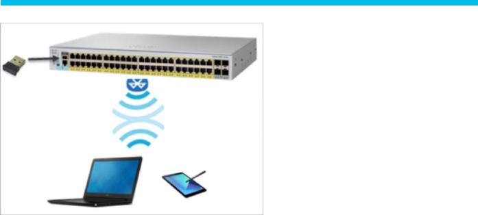
Figure 2.
Over-the-air switch access using Bluetooth
●Single IP Management is available on the Cisco Catalyst 1000 Series switches. The uplink ports can be used to connect up to eight switches and manage them via a single IP address.
Network management
The Cisco Catalyst 1000 Series Switches offer a superior CLI for detailed configuration and administration.
Intelligent PoE+
Cisco Catalyst 1000 Series Switches support both IEEE 802.3af PoE and IEEE 802.3at PoE+ (up to 30W per port) to deliver a lower total cost of ownership for deployments that incorporate Cisco IP phones, Cisco Aironet® and Catalyst wireless access points, or other standards-compliant PoE and PoE+ end devices. PoE removes the need to supply wall power to PoE-enabled devices and eliminates the cost of adding electrical cabling and circuits that would otherwise be necessary in IP phone and WLAN deployments.
The PoE power allocation in the Cisco Catalyst 1000 Series Switches is dynamic, and power mapping scales up to a maximum of 740W of PoE+ power. Intelligent power management allows flexible power allocation across all ports. With Perpetual PoE, the PoE+ power is maintained during a switch reload. This is important for critical endpoints such as medical devices and for IoT endpoints such as PoE-powered lights, so that there is no disruption during a switch reboot.
© 2020 Cisco and/or its affiliates. All rights reserved. |
Page 6 of 21 |

Network security
Cisco Catalyst 1000 Series Switches provide a range of security features to limit access to the network and mitigate threats, including:
●Comprehensive 802.1X features to control access to the network, including flexible authentication, 802.1X monitor mode, and RADIUS change of authorization.
●802.1X support with Network Edge Access Topology (NEAT), which extends identity authentication to areas outside the wiring closet (such as conference rooms).
●IEEE 802.1X user distribution, which enables you to load-balance users with the same group name across multiple different VLANs.
●Ability to disable per-VLAN MAC learning to allow you to manage the available MAC address table space by controlling which interface or VLANs learn MAC addresses.
●Multidomain authentication to allow an IP phone and a PC to authenticate on the same switch port while being placed on the appropriate voice and data VLANs.
●Authentication, Authorization, and Accounting (AAA) command authorization in PnP to enable seamless PnP provisioning.
●Access Control Lists (ACLS) for IPv6 and IPv4 security and Quality-of-Service (QoS) ACL elements (ACEs).
●Port-based ACLs for Layer 2 interfaces to allow security policies to be applied on individual switch ports.
●SSH, Kerberos, and SNMP v3 to provide network security by encrypting administrator traffic during Telnet and SNMP sessions. SSH, Kerberos, and the cryptographic version of SNMP v3 require a special cryptographic software image because of U.S. export restrictions.
●SPAN, with bidirectional data support, to allow the Cisco Intrusion Detection System (IDS) to take action when an intruder is detected.
●TACACS+ and RADIUS authentication to facilitate centralized control of the switch and restrict unauthorized users from altering the configuration.
●MAC address notification to notify administrators about users added to or removed from the network.
●MAC Authentication Bypass (MAB) and WebAuth with downloadable ACLs to allow per-user ACLs to be downloaded from the Cisco Identity Services Engine (ISE) as policy enforcement after authentication using MAB or web authentication in addition to IEEE 802.1X.
●Web authentication redirection to enable networks to redirect guest users to the URL they had originally requested.
●Multilevel security on console access to prevent unauthorized users from altering the switch configuration.
●BPDU Guard to shut down Spanning Tree PortFast-enabled interfaces when BPDUs are received, to avoid accidental topology loops.
●IP Source Guard to restrict IP traffic on nonrouted Layer 2 interfaces by filtering traffic based on the Dynamic Host Configuration Protocol (DHCP) snooping binding database or by manually configuring IP source bindings.
© 2020 Cisco and/or its affiliates. All rights reserved. |
Page 7 of 21 |
 Loading...