


 Loading...
PIXMA MX870
SERVICE
MANUAL
Canon
Copyright © 2010, Canon U.S.A. This technical publication is the proprietary and confidential information of Canon U.S.A. which shall be retained for reference purposes by Authorized Service Facilities of Canon U.S.A. Its unauthorized use is prohibited.

MX870
TABLE OF CONTENTS
1.MAINTENANCE
1-1. Adjustment, Periodic Maintenance, Periodic Replacement Parts, and Replacement Consumables by Service Engineer
1-2. Customer Maintenance
1-3. Special Tools
1-4. Sensors
1-5. Serial Number Location
2.LIST OF ERROR DISPLAY / TROUBLESHOOTING
2-1. Operator Call Errors
2-2. Service Call Errors
2-3. FAX Errors
2-4. Troubleshooting by Symptom
3.REPAIR
3-1. Major Replacement Parts
3-2. Part Replacement Procedures
(1)External housing, scanner unit, and document cover removal
(2)Operation panel and document feed unit removal
(3)Printer unit removal, and ink absorber replacement
(4)Board removal
(5)Carriage unlocking
(6)ASF unit removal
(7)Carriage unit removal
(8)Spur unit and platen unit removal
(9)Purge drive system unit (right plate) and switch system unit (left plate) removal
(10)Engine unit reassembly
4.ADJUSTMENT / SETTINGS
4-1. User Mode
4-2. Service Mode
(1)Service mode operation procedures
(2)Service Tool functions
(3)LF / Eject correction
(4)Button and LCD test
(5)Ink absorber counter setting
4-3. PTT Parameter Mode
4-4. Grease Application
4-5. Special Notes on Servicing
(1)For smeared printing, uneven printing, or non-ejection of ink
(2)Paper feed motor adjustment
(3)Carriage unit replacement
(4)Document pressure sheet (sponge sheet) replacement
(5)Ink absorber counter setting
(6)Ink absorber life estimation
(7)Power supply unit and modular board replacement
(8)Rating label on the bottom case (except China)
(9)PTT label on the bottom case (for New Zealand only)
(10)Speed Dial Utility
4-6. Verification After Repair
(1)Standard inspection flow
(2)Service test print
(3)Ink absorber counter value print
5.MACHINE TRANSPORTATION
<TABLE OF CONTENTS>

MX870 |
TABLE OF CONTENTS |
|
|
1. MAINTENANCE
1-1. Adjustment, Periodic Maintenance, Periodic Replacement Parts, and Replacement Consumables by Service Engineer
(1) Adjustment
|
|
Adjustment |
|
Timing |
|
Purpose |
|
Tool |
|
Approx. |
|
|
|
|
|
|
time |
||||
|
|
|
|
|
|
|
|
|
|
|
|
|
EEPROM |
|
- At logic board replacement |
|
To initialize settings |
|
Service Tool*1 |
|
1 min. |
|
|
initialization |
|
|
|
|
|
Perform in the service |
|
|
|
|
|
|
|
|
|
|
mode. |
|
|
Destination |
- At logic board replacement |
To set destination. |
settings |
|
|
(EEPROM |
|
|
settings) |
|
|
Ink absorber |
- At logic board replacement |
To reset the ink absorber |
counter resetting |
- At ink absorber replacement |
counter. |
(EEPROM |
|
|
settings) |
|
|
Ink absorber |
- At logic board replacement |
To set the ink amount data in |
counter value |
|
the ink absorber to the ink |
setting |
|
absorber counter. |
(EEPROM |
|
|
settings) |
|
|
Service Tool*1 |
1 min. |
Perform in the service |
|
mode. |
|
Service Tool*1 |
1 min. |
Perform in the service |
|
mode. |
|
Service Tool*1 |
1 min. |
Perform in the service |
|
mode. |
|
Ink absorber |
- When the ink absorber |
To replace the ink absorber |
Screwdriver, a pair of |
15 min. |
replacement |
becomes full |
with a new one. |
tweezers, etc. |
|
Paper feed motor |
- At paper feed motor |
To adjust the belt tension. |
None. |
5 min. |
position |
replacement |
(Position the paper feed motor |
|
|
adjustment |
|
so that the belt is stretched |
|
|
|
|
tight.) |
|
|
N Automatic print |
- At print head replacement |
head alignment |
- At logic board replacement |
|
- When print quality is not |
|
satisfying |
To secure the dot placement |
None. |
6 min. |
accuracy. |
Perform in the user |
|
|
mode. |
|
Manual print head |
- At print head replacement |
alignment |
- At logic board replacement |
|
- When print quality is not |
|
satisfying |
To secure the dot placement |
None. |
10 min. |
accuracy. |
Perform in the user |
|
|
mode. |
|
Grease application - At carriage unit replacement To maintain sliding properties FLOIL KG-107A |
1 min. |
of the carriage rail. |
|
Ink system |
- At logic board replacement |
To maintain detection |
function check |
- At spur unit replacement |
functionality for presence of |
|
- At carriage unit replacement |
the ink tanks and each ink tank |
|
|
position. |
Service Tool*1 |
1 min. |
Perform in the service |
|
mode. |
|
LCD language |
- At logic board replacement |
To set the language to be |
None. |
1 min. |
settings |
|
displayed on the LCD. |
Perform in the user |
|
|
|
|
mode. |
|
Platen glass |
- At protection sheet |
To maintain scanning |
None. |
1 min. |
protection sheet |
replacement |
accuracy, hold the sheet with |
|
|
(document |
- At document bottom cover |
the long side down, then fit its |
|
|
pressure sheet) |
replacement |
upper left corner to the platen |
|
|
position |
- At scanner unit replacement |
glass reference mark (back |
|
|
1 / 63

adjustment |
|
left). |
LF / Eject |
- At logic board replacement |
To correct line feeding (LF |
correction |
- At paper feed roller |
roller diameter). |
|
replacement |
|
|
- At logic board replacement |
To correct line feeding (eject |
|
- At platen unit replacement |
roller diameter). |
Service Tool*1 |
5 min. |
|
Perform in the service |
(LF |
|
mode. |
correction |
|
|
and Eject |
|
Service Tool*1 |
correction |
|
is |
||
Perform in the service |
performed |
|
mode. |
||
at the same |
||
|
||
|
time.) |
Carriage rail |
- At carriage unit replacement |
To set the carriage rail to the |
None. |
1 min. |
position |
- At carriage unit removal |
original position prior to |
|
|
adjustment |
|
removal or replacement of the |
|
|
|
|
carriage unit, put a mark on the |
|
|
|
|
main chassis before removal of |
|
|
|
|
the carriage unit. |
|
|
FAX user data |
- At logic board replacement |
To confirm the FAX user data |
None. |
2 min. |
settings |
- At modular board |
settings. |
Perform in the user |
|
|
replacement |
|
mode. |
|
N: New adjustment item
*1: Install the Service Tool version 1.072 or later to a pre-registered computer.
-The screws securing the paper feed motor may be loosened only at replacement of the paper feed motor unit.
-For print head alignment, perform manual print head alignment using plain paper.
(2)Periodic maintenance
No periodic maintenance is necessary.
(3) Periodic replacement parts
There are no parts in this machine that require periodic replacement by a service engineer.
(4) Replacement consumables
There are no consumables that require replacement by a service engineer.
2 / 63

1-2. Customer Maintenance
Adjustment |
|
Timing |
|
|
|
Automatic |
|
- At print head replacement |
print head |
|
- When print quality is not satisfying |
alignment |
|
(uneven printing, etc.) |
Manual print |
|
- At print head replacement |
head |
|
- When print quality is not satisfying |
alignment |
|
(uneven printing, etc.) |
Print head |
|
When print quality is not satisfying. |
cleaning |
|
|
Print head |
|
When print quality is not satisfying, |
deep cleaning |
|
and not improved by print head |
|
|
cleaning. |
Ink tank |
|
When an ink tank becomes empty. |
replacement |
|
("No ink error" displayed on the |
|
|
monitor or on the machine LCD, or |
|
|
short flashing of an ink tank LED) |
Paper feed |
|
- When paper does not feed properly. |
roller cleaning |
|
- When the front side of the paper is |
|
|
smeared. |
Bottom plate |
|
When the back side of the paper is |
cleaning |
|
smeared. |
Scanning area |
|
When the platen glass or document |
cleaning |
|
pressure sheet is dirty. |
Exterior |
|
When necessary |
cleaning |
|
|
Purpose |
|
Tool |
|
Approx. |
|
|
time |
||
|
|
|
|
|
To ensure accurate dot |
|
- Machine buttons |
|
6 min. |
placement. |
|
- Computer (MP driver) |
|
|
To ensure accurate dot |
|
- Machine buttons |
|
10 min. |
placement. |
|
- Computer (MP driver) |
|
|
To improve nozzle |
|
- Machine buttons |
|
1 min. |
conditions. |
|
- Computer (MP driver) |
|
|
To improve nozzle |
|
- Machine buttons |
|
2 min. |
conditions. |
|
- Computer (MP driver) |
|
|
To replace the empty ink |
--- |
|
1 min. |
|
tank. |
|
|
|
|
To clean the paper feed |
|
- Machine buttons |
|
2 min. |
rollers of the selected paper |
|
- Computer (MP driver) |
|
|
source (rear tray or cassette). |
|
|
|
|
To clean the platen ribs. |
|
- Machine buttons |
|
1 min. |
(Feed the paper from the |
|
- Computer (MP driver) |
|
|
rear tray.) |
|
|
|
|
To clean the platen glass and |
|
Soft, dry, and clean lint- |
|
1 min. |
pressure sheet. |
|
free cloth. |
|
|
To clean the machine |
|
Soft, dry, and clean lint- |
|
1 min. |
exterior, or to wipe off |
|
free cloth. |
|
|
dusts. |
|
|
|
|
3 / 63

1-3. Special Tools
Name |
|
Tool No. |
|
Application |
|
Remarks |
FLOIL KG-107A |
|
QY9-0057-000 |
|
To the carriage rail sliding portions. |
|
In common with the MP610, etc. |
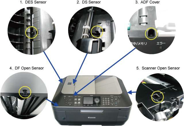
1-4. Sensors
No. |
|
Sensor |
|
Function |
|
Possible problems |
1 |
|
DES sensor |
|
Detects paper ejection from the ADF. |
|
- Paper jam in the ADF |
2 |
|
DS sensor |
|
Detects paper feeding from the ADF. |
|
- No paper in the ADF |
3 |
|
ADF cover sensor |
|
Detects opening and closing of the |
|
- Although the document feeder cover is closed, the |
|
|
|
|
document feeder cover. |
|
machine indicates that the cover is open. |
4 |
|
DF open sensor |
|
Detects opening and closing of the |
|
- The machine stays in the sleep mode even when the |
|
|
|
|
ADF. |
|
document feeder is opened. |
5 |
|
Scanner open sensor |
|
Detects opening and closing of the |
|
- The carriage does not move to the center even when the |
|
|
|
|
scanning unit (cover). |
|
scanning unit (cover) is opened. |
6 |
|
PE sensor |
|
Detects the positions of the leading |
|
- No paper |
|
|
|
|
and trailing edges of paper. |
|
- Paper jam |
7 |
|
ASF cam sensor |
|
Detects the position of the ASF cam |
|
- ASF cam sensor error |
|
|
|
|
(during paper feeding from the rear |
|
- Paper feed problem |
|
|
|
|
tray). |
|
|
8 |
|
APP encoder sensor |
|
Detects the amount of rotation of the |
|
- APP sensor error |
|
|
|
|
APP encoder. (Controls purging |
|
- APP position error |
|
|
|
|
operation and paper feeding from the |
|
|
|
|
|
|
rear tray or from the cassette). |
|
|
9 |
|
LF encoder sensor |
|
Detects the amount of rotation of the |
|
- LF position error |
|
|
|
|
LF encoder. |
|
- Uneven printing |
10 |
|
Carriage encoder |
|
Detects the position of the carriage. |
|
- Carriage position error |
|
|
sensor |
|
|
|
- Printing shifts from the correct position. |
|
|
|
|
|
|
- Uneven printing |
|
|
|
|
|
|
- Strange sound |
11 |
|
Temperature & Ink |
|
Detects the temperature of the inside |
|
- Internal temperature error |
|
|
amount sensor |
|
of the machine and the remaining ink |
|
- Low-ink or out-of-ink warning |
|
|
|
|
amount. |
|
|
12 |
|
Ink sensor |
|
Detects the position of an ink tank. |
|
- Wrong position of an ink tank |
|
|
|
|
|
|
- An error indicating that multiple ink tanks of the same |
|
|
|
|
|
|
color are installed |
|
|
|
|
|
|
- No recognition of an ink tank |
13 |
|
Valve cam sensor |
|
Detects the position of the purge |
|
- Valve cam sensor error |
|
|
|
|
valve cam. (Controls purging |
|
|
|
|
|
|
operation.) |
|
|
14 |
|
Pump roller sensor |
|
Detects the position of the purge |
|
- Pump roller sensor error |
|
|
|
|
pump roller. (Controls purging |
|
|
|
|
|
|
operation.) |
|
|
15 |
|
Purge cam sensor |
|
Detects the position of the purge main |
|
- Purge cam sensor error |
|
|
|
|
cam. (Controls purging operation.) |
|
|
4 / 63
5 / 63

6 / 63
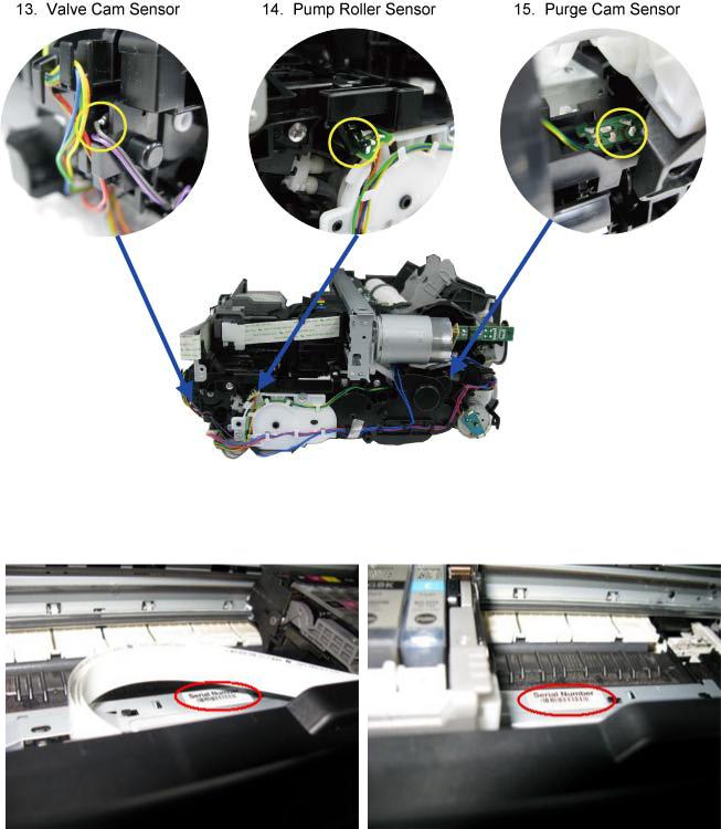
1-5. Serial Number Location
On the inner guide over the upper portion of the spur holder (visible when the scanning unit (cover) is opened)
When the machine power is OFF. |
When the machine power is ON. |
<1. MAINTENANCE>
7 / 63
MX870 |
TABLE OF CONTENTS |
|
|
2. LIST OF ERROR DISPLAY / TROUBLESHOOTING
Errors and warnings are displayed by the following ways:
1.Operator call errors are indicated by the Alarm LED lit in orange, and the error and its solution are displayed on the LCD in text and by icon.
2.Messages during printing from a computer are displayed on the MP driver Status Monitor.
3.Error codes (the latest 10 error codes at the maximum) are printed in the "operator call/service call error record" area in EEPROM information print
Buttons valid when an operator call error occurs:
1.ON button: To turn the machine off and on again.
2.OK button: To clear and recover from an error. In some operator call errors, the error will automatically be cleared when the cause of the error is eliminated, and pressing the OK button may not be necessary.
3.Stop button: To cancel the job at error occurrence, and to clear the error.
2-1. Operator Call Errors (by Alarm LED Lit in Orange)
Error
No paper in the rear tray.
Error |
|
U |
|
Message on the |
code |
|
No. |
|
LCD |
[1000] |
--- |
|
Rear tray. |
|
|
|
|
|
There is no paper. |
|
|
|
|
Load paper and |
|
|
|
|
press [OK]. |
Solution
Confirm that the rear tray is selected as the paper source. Set the paper in the rear tray, and press the OK button.
Parts that are likely to be faulty
-ASF unit
-Pressure roller unit
-Switch system unit
-Paper feed motor
No paper in the |
[1003] --- Cassette. |
Confirm that the cassette is selected as the |
- Pick-up arm unit |
cassette. |
There is no paper. |
paper source. Set the paper in the cassette, |
- Pressure roller unit |
|
Load paper and |
and press the OK button. |
- Switch system |
|
press [OK]. |
|
unit |
|
|
|
- Paper feed motor |
Paper jam.
Paper jam in the rear guide.
Paper jam in the under guide.
Ink may have run out.
[1300] |
--- |
The paper is |
Remove the jammed paper or foreign material |
- ASF unit |
|
[1303] |
--- |
jammed. Clear the |
causing a paper jam (paper remainings, clips, |
- Pick-up arm unit |
|
paper and press |
pens, etc.), and press the OK button. |
- Cassette unit |
|||
|
|
||||
[1304] |
--- |
[OK]. |
|
- Pressure roller unit |
|
|
|
|
|||
[1600] |
U041 |
The following ink |
Replace the applicable ink tank, or press the |
- Ink tank |
|
|
|
may have run out. |
OK button to clear the error without ink tank |
- Spur unit |
|
|
|
Replacing the ink |
replacement. When the error is cleared by |
- Logic board |
|
|
|
tank is |
pressing the OK button, ink may run out |
|
|
|
|
recommended. |
during printing. |
|
Ink tank not |
[1660] U043 The following ink |
Install the applicable ink tank(s) properly, and |
- Ink tank |
installed. |
tank cannot be |
confirm that the LED's of all the ink tanks |
- Carriage unit |
|
recognized. |
light red. |
- Logic board |
|
(Applicable ink |
|
|
|
tank icon) |
|
|
Print head not |
[1401] U051 |
Print head is not |
|
installed, or not |
|
installed. Install the |
|
properly installed. |
|
print head. |
|
Faulty print head |
U052 |
The type of print |
|
ID. |
|
head is incorrect. |
|
Print head |
[1403] |
Install the correct |
|
print head. |
|||
temperature sensor |
|
||
|
|
Install the print head properly. |
- Print head |
|
- Carriage unit |
|
- Logic board |
Re-set the print head. If the error is not |
- Print head |
cleared, the print head may be defective. |
- Logic board |
Replace the print head. |
|
8 / 63

error. |
|
Faulty EEPROM |
[1405] |
data of the print |
|
head. |
|
Multiple ink tanks |
[1487] U071 More than one ink |
of the same color |
tank of the |
installed. |
following color is |
|
installed. |
Replace the wrong ink tank(s) with the correct |
- Ink tank |
one(s). |
- Logic board |
Ink tank in a wrong |
[1680] |
U072 |
Some ink tanks are |
Install the ink tank(s) in the correct position. |
- Ink tank |
position. |
|
|
not installed in |
|
- Logic board |
|
|
|
place. |
|
|
Warning: The ink |
[1700] |
--- |
Contact the support |
Replace the ink absorber, and reset its |
- Absorber kit |
absorber becomes |
|
|
center or service |
counter. [See 4-5. Special Notes on Servicing, |
|
almost full. |
|
|
center for ink |
(5) Ink absorber counter setting.] |
|
|
|
|
absorber |
Pressing the OK button will exit the error, and |
|
|
|
|
replacement. Press |
enable printing without replacing the ink |
|
|
|
|
[OK] to continue |
absorber. However, when the ink absorber |
|
|
|
|
printing. |
becomes full, no further printing can be |
|
|
|
|
|
performed unless the applicable ink absorber |
|
|
|
|
|
is replaced. |
|
The connected |
[2001] |
--- |
Incompatible |
Remove the cable between the camera and the |
- PictBridge board |
digital camera or |
|
|
device detected. |
machine. |
- Logic board |
digital video |
|
|
Remove the |
|
|
camera does not |
|
|
device. |
|
|
support Camera |
|
|
|
|
|
Direct Printing. |
|
|
|
|
|
Automatic duplex |
[1310] |
--- |
This paper is not |
The paper length is not supported for duplex |
- Duplex feed roller |
printing cannot be |
|
|
compatible with |
printing. |
unit |
performed. |
|
|
duplex printing. |
Press the OK button to eject the paper being |
- PE sensor board |
|
|
|
Remove the paper |
used at error occurrence. |
- Logic board |
|
|
|
and press [OK]. |
Data which was to be printed on the back side |
|
|
|
|
|
of paper at error occurrence is skipped (not |
|
|
|
|
|
printed). |
|
The remaining ink |
[1683] |
U130 |
(Applicable ink |
An ink tank which has once been empty is |
- Ink tank |
amount unknown |
|
|
tank icon) |
installed. Replace the applicable ink tank with |
- Spur unit |
(raw ink present). |
|
|
The remaining |
a new one. Printing with a once-empty ink |
|
|
|
|
level of the ink |
tank can damage the machine. |
|
|
|
|
cannot be correctly |
To continue printing without replacing the ink |
|
|
|
|
detected. |
tank(s), press the Stop button for 5 sec. or |
|
|
|
|
|
longer to disable the function to detect the |
|
|
|
|
|
remaining ink amount. After the operation, it |
|
|
|
|
|
is recorded in the machine EEPROM that the |
|
|
|
|
|
function to detect the remaining ink amount |
|
|
|
|
|
was disabled. |
|
Ink tank not |
[1684] |
U140 |
The following ink |
A non-supported ink tank (an ink tank that is |
- Ink tank |
recognized. |
|
|
tank cannot be |
sold in a different region from where the |
- Logic board |
|
|
|
recognized. |
machine was purchased) is installed (the ink |
|
|
|
|
(Applicable ink |
tank LED is turned off). Install the supported |
|
|
|
|
tank icon) |
ink tanks. |
|
Ink tank not |
[1682] |
U150 |
The following ink |
A hardware error occurred in an ink tank (the |
- Ink tank |
recognized. |
|
|
tank cannot be |
ink tank LED is turned off). Replace the ink |
- Logic board |
|
|
|
recognized. |
tank(s). |
|
|
|
|
(Applicable ink |
|
|
|
|
|
tank icon) |
|
|
No ink (no raw |
[1688] U163 The ink has run |
ink). |
out. Replace the |
Replace the empty ink tank(s), and close the |
- Ink tank |
scanning unit (cover). |
- Spur unit |
9 / 63

|
|
|
ink tank. |
Printing with an empty ink tank can damage |
- Logic board |
|
|
|
(Applicable ink |
the machine. |
|
|
|
|
tank icon) |
To continue printing without replacing the ink |
|
|
|
|
|
tank(s), press the Stop button for 5 sec. or |
|
|
|
|
|
longer to disable the function to detect the |
|
|
|
|
|
remaining ink amount. After the operation, it |
|
|
|
|
|
is recorded in the machine that the function to |
|
|
|
|
|
detect the remaining ink amount was disabled. |
|
Non-supported |
[2002] |
--- |
An unsupported |
Remove the applicable USB hub from the |
- PictBridge board |
hub. |
|
|
USB hub is |
PictBridge (USB) connector. |
- Logic board |
|
|
|
connected. |
|
|
|
|
|
Remove the hub. |
|
|
Document cover |
[2800] |
--- The feeder cover is |
Close the document cover, and press the OK |
- DF unit |
|
not closed. |
|
|
open. Close cover |
button. |
- DF switch unit |
|
|
|
and press [OK]. |
|
|
Paper jam in the |
[2801] |
--- |
Document in ADF. |
Remove the paper from the ADF, and press |
- DF unit |
ADF. |
|
|
Redo operation |
the OK button. |
|
|
|
|
after checking |
|
|
|
|
|
document in ADF |
|
|
|
|
|
and pressing [OK]. |
|
|
No paper in the |
[2802] |
--- |
No document in |
Press the OK button to clear the error. |
- DF unit |
ADF. |
|
|
ADF. Press [OK] |
|
|
|
|
|
and redo operation |
|
|
|
|
|
after setting |
|
|
|
|
|
document. |
|
|
Paper in the ADF |
[2803] |
--- |
Document size is |
Remove the paper from the ADF, and press |
- DF unit |
is too long. |
|
|
too long. Redo |
the OK button. |
|
|
|
|
operation after |
|
|
|
|
|
checking document |
|
|
|
|
|
on ADF and |
|
|
|
|
|
pressing [OK]. |
|
|
Duplex printing |
[2804] |
--- |
Document size not |
Remove the paper from the ADF, and press |
- DF unit |
not available with |
|
|
suitable for two- |
the OK button. |
|
the paper in the |
|
|
sided scanning. |
|
|
ADF. |
|
|
Press [OK] to |
|
|
|
|
|
cancel operation |
|
|
|
|
|
and discharge |
|
|
|
|
|
document. |
|
|
Time-out for the |
[2700] |
--- |
Timeout error has |
The buffer became full in the middle of |
|
scanner device. |
|
|
occurred. Press |
scanning operation, and 60 minutes have |
|
|
|
|
[OK]. |
elapsed since then, making re-scanning |
|
|
|
|
|
unstable. Press the OK button to clear the |
|
|
|
|
|
error. |
|
10 / 63

2-2. Service Call Errors (by Cyclic Blinking of Alarm and Power LEDs)
Service call errors are indicated by the number of cycles the Alarm and Power LEDs blink, and the corresponding error code with the message,
"Printer error has occurred. Turn off power then back on again. If problem persists, see the manual." is displayed on the LCD.
Cycles |
|
|
|
|
|
|
of |
|
|
|
|
|
|
blinking |
|
|
|
|
|
|
of |
|
Error |
|
Error |
|
Conditions |
Alarm |
|
|
code |
|
||
|
|
|
|
|
||
and |
|
|
|
|
|
|
Power |
|
|
|
|
|
|
LEDs |
|
|
|
|
|
|
2 times Carriage |
|
[5100] An error occurred in the carriage |
||||
|
|
error |
|
|
|
encoder signal. |
Solution
(Check points and replacement items)
(1)Smearing or scratches on the carriage slit film; clean the timing slit film.
(2)Foreign material or paper debris that obstructs the carriage movement;
remove foreign material.
(3)Ink tank conditions;
re-set the ink tanks.
(4)Cable connection
(5)Part replacement:
-Timing slit disk film
-Carriage unit
-Logic board
-Carriage motor
3 times |
Line feed |
[6000] An error occurred in the LF |
(1) |
Opening and closing of the paper output tray; |
|
error |
encoder signal. |
|
the tray must be opened properly. |
|
|
|
(2) |
Smearing or scratches on the LF / EJ slit film; |
|
|
|
|
clean the LF / EJ slit film. |
|
|
|
(3) |
Foreign material or paper debris in the LF drive; |
|
|
|
|
remove foreign material. |
|
|
|
(4) |
Cable connection |
|
|
|
(5) |
Part replacement: |
|
|
|
|
- LF / EJ slit film |
|
|
|
|
- LF / EJ timing sensor unit |
|
|
|
|
- Paper feed roller unit |
|
|
|
|
- Logic board |
|
|
|
|
- Paper feed motor |
4 times |
Purge cam |
[5C00] An error occurred in the purge |
(1) |
Foreign material or paper debris around the purge |
|
sensor error |
unit. |
|
drive system unit; |
|
|
|
|
remove foreign material. |
|
|
|
(2) |
Cable connection |
|
|
|
(3) |
Part replacement: |
|
|
|
|
- Purge drive system unit |
|
|
|
|
- Logic board |
5 times |
ASF (cam) |
[5700] An error occurred in the ASF |
(1) |
Cable connection |
|
sensor error |
cam sensor. |
(2) |
Part replacement: |
|
|
|
|
- ASF unit |
|
|
|
|
- PE sensor board unit |
|
|
|
|
- Logic board |
6 times |
Internal |
[5400] The internal temperature is not |
(1) |
Cable connection |
|
temperature |
normal. |
(2) |
Part replacement: |
|
error |
|
|
- Spur unit |
|
|
|
|
- Logic board |
|
|
|
|
- Print head |
7 times |
Ink |
[5B00] The ink absorber is supposed to |
(1) |
Ink absorber condition |
|
absorber |
[5B01] be full. |
(2) |
Part replacement: |
11 / 63

|
full |
|
Message on the LCD: |
|
- Ink absorber kit and double-sided adhesive tape |
|
|
|
Ink absorber full. Service |
(3) |
Ink absorber counter value in the EEPROM; |
|
|
|
required. |
|
reset the ink absorber counter. |
|
|
|
Error codes: |
|
|
|
|
|
5B00: Main ink absorber is |
|
|
|
|
|
full (overseas). |
|
|
|
|
|
5B01: Main ink absorber is |
|
|
|
|
|
full (Japan). (In EEPROM |
|
|
|
|
|
information print, "5B00" is |
|
|
|
|
|
printed instead of "5B01.") |
|
|
8 times |
Print head |
[5200] The print head temperature |
(1) |
Print head condition |
|
|
temperature |
|
exceeded the specified value. |
(2) |
Head contact pin condition of the carriage unit |
|
rise error |
|
|
(3) |
Cable connection |
|
|
|
|
(4) |
Part replacement: |
|
|
|
|
|
- Print head |
|
|
|
|
|
- Logic board |
|
|
|
|
|
- Carriage unit |
9 times |
EEPROM |
[6800] A problem occurred in reading |
(1) |
Part replacement: |
|
|
error |
[6801] |
from or writing to the EEPROM. |
|
- Logic board |
10 times |
VH |
[B200] |
The internal temperature |
(1) |
Head contact pin condition of the carriage unit |
|
monitor |
|
exceeded the specified value. |
(2) |
Cable connection (especially the carriage FFC) |
|
error |
|
|
(3) |
Part replacement: |
|
|
|
|
|
- Print head and logic board (Replace them at the |
|
|
|
|
|
same time.) |
|
|
|
|
|
- Power supply unit |
|
|
|
|
|
- Carriage unit |
11 times |
Carriage |
[5110] The carriage did not move up or |
(1) |
Foreign material or paper debris that obstructs the |
|
|
lift |
|
down properly. |
|
carriage movement; |
|
mechanism |
|
|
|
remove foreign material. |
|
error |
|
|
(2) |
Part replacement: |
|
|
|
|
|
- Switch system unit |
|
|
|
|
|
- Carriage unit |
12 times APP |
[6A80] An error occurred in the APP |
position |
motor. |
error |
|
14 times APP sensor |
[6A90] An error occurred during paper |
error |
feeding or purging. |
(1)Foreign material or paper debris around the purge drive system unit;
remove foreign material, and
confirm that the ink absorber right beneath the purge drive system unit stays in place and does not contact the unit.
(2)Foreign material or paper debris around the ASF unit; remove foreign material.
(3)Cable connection
(4)Part replacement:
-Purge drive system unit
-Logic board
|
Paper feed |
[6B10] |
An error occurred in the paper |
(1) |
Jammed paper in the PF rear guide (when a large |
|
cam sensor |
|
feed cam sensor during paper |
|
amount of ink was absorbed in the paper); |
|
error |
|
feeding from the cassette, or the |
|
remove the jammed paper and foreign material. |
|
|
|
paper absorbing a large amount |
(2) |
Foreign material or paper debris in the cassette or in |
|
|
|
of ink jammed in the PF rear |
|
the PF rear guide; |
|
|
|
guide. |
|
remove foreign material. |
|
|
|
|
(3) |
Part replacement: |
|
|
|
|
|
- PF pick-up unit |
|
|
|
|
|
- Logic board |
15 times |
USB host |
[9000] |
The USB host Vbus overloaded. |
(1) |
Part replacement: |
|
Vbus |
|
|
|
- Logic board |
|
overcurrent |
|
|
|
|
16 times |
Pump roller |
[5C20] |
The pump roller position cannot |
(1) |
Cable connection |
12 / 63

|
sensor error |
be detected. |
(2) |
Part replacement: |
|
|
|
|
- Purge drive system unit |
17 times |
Paper eject |
[6010] An error occurred in the paper |
(1) |
Smearing or scratches on the LF / EJ slit film; |
|
encoder |
eject encoder signal. |
|
clean the LF / EJ slit film. |
|
error |
|
(2) |
Foreign material or paper debris in the paper path; |
|
|
|
|
remove foreign material. |
|
|
|
(3) |
Cable connection |
|
|
|
(4) |
Part replacement: |
|
|
|
|
- LF / EJ slit film |
|
|
|
|
- LF / EJ timing sensor unit |
|
|
|
|
- Platen unit |
|
|
|
|
- Logic board |
|
|
|
|
- Paper feed motor |
19 times |
Ink tank |
[6502] None of the ink tank position is |
(1) |
Ink tank position; |
|
position |
detected. |
|
confirm the ink tank position. |
|
sensor error |
|
(2) |
Re-set or replacement of ink tanks |
|
|
|
(3) |
Cable connection |
|
|
|
(4) |
Part replacement: |
|
|
|
|
- Spur unit |
|
|
|
|
- Logic board |
20 times |
Other |
[6500] An unidentified error or a |
(1) |
Part replacement: |
|
errors |
network error occurred. |
|
- Logic board |
21 times |
Drive |
[C000] Drive was not switched |
(1) |
Foreign material or paper debris in the drive switch |
|
switch |
properly. |
|
area; |
|
error |
|
|
remove foreign material. |
|
|
|
(2) |
Ink tank conditions; |
|
|
|
|
confirm that the ink tanks are seated properly, or |
|
|
|
|
re-set the ink tanks properly. |
|
|
|
(3) |
Part replacement: |
|
|
|
|
- Carriage unit |
|
|
|
|
- Purge drive system unit |
|
|
|
|
- ASF unit |
22 times |
Scanner |
[5011] An error occurred in the scanner. |
(1) |
Document pressure sheet conditions |
|
error |
|
(1) |
Cable connection |
|
|
|
(2) |
Part replacement: |
|
|
|
|
- Document pressure sheet (sponge sheet) |
|
|
|
|
- Scanner unit |
|
|
|
|
- Logic board |
|
FB motor |
[5012] An error occurred in the scanner |
(1) |
Cable connection |
|
error |
FB motor. |
(2) |
Part replacement: |
|
|
|
|
- Scanner unit |
23 times |
Valve cam |
[6C10] The valve cam sensor was faulty |
(1) |
Foreign material or paper debris around the purge |
|
sensor error |
at power-on or when purging |
|
drive system unit; |
|
|
was attempted. |
|
remove foreign material. |
|
|
|
(2) |
Cable connection |
|
|
|
(3) |
Part replacement: |
|
|
|
|
- Purge drive system unit |
|
|
|
|
- Logic board |
Before replacement of the logic board ass'y, check the ink absorber counter value (by service test print or EEPROM information print). If the counter value is 7% or more, also replace the ink absorber kit when replacing the logic board ass'y. If the counter value is less than 7%, register the current ink absorber counter value to the replaced new logic board instead. [See 4-5. Special Notes on Servicing, (5) Ink absorber counter setting, for details.]
13 / 63
2-3. FAX Errors
For errors other than those listed below, please refer to the "G3 / G4 Facsimile Error Code List (Rev. 2." (HY8-22A6-020 in English).
(1) User error codes
Error code |
|
TX / RX |
|
Meaning |
|
|
|
|
|
#001 |
|
TX |
|
Document jam |
#003 |
|
TX / RX |
|
Document is too long, or page time-over |
#005 |
|
TX / RX |
|
Initial identification (T0 / T1) time-over |
#009 |
|
RX |
|
Recording paper jam, or no recording paper |
Solution
(Parts that are likely to be faulty)
-DF unit
-DF unit
-Check the telephone line type settings (rotary pulse / touch tone).
-ASF unit
-Pick-up arm unit
-Cassette unit
-Pressure roller unit
#012 |
TX |
No recording paper at the receiving machine |
|
#017 |
TX |
Redial time-over, but no DT detected |
|
#018 |
TX |
Auto dialing transmission error, or redial time-over |
- Check the telephone line type settings (rotary |
|
|
|
pulse / touch tone). |
#022 |
TX |
Call failed (no dial registration) |
- Register a dial number. |
#037 |
RX |
Memory overflow at reception of an image |
- Delete unnecessary image data from the |
|
|
|
memory. |
#085 |
TX |
No color fax function supported in the receiving |
- Send a fax in the B&W mode. |
|
|
machine |
|
#099 |
TX / RX |
Transmission terminated mid-way by pressing the |
|
|
|
Stop/Reset button |
|
#995 |
TX / RX |
During TX (sending): Memory transmission |
|
|
|
reservation cancelled |
|
During RX (receiving): Image data received in the memory cleared
(2) Service error codes
Error code |
|
TX / RX |
|
Meaning |
|
|
|
|
|
##100 |
|
TX |
|
Re-transmission of the procedure signal has been attempted the |
|
|
|
|
specified number of times, but failed. |
Solution
(Parts that are likely to be faulty)
- Try a higher transmission level.
##101 |
TX / RX |
Sender's modem speed does not match the receiving machine. |
##102 |
TX |
Fallback is not available. |
##103 |
RX |
EOL has not been detected for 5 seconds (or 15 seconds in |
|
|
CBT). |
##104 |
TX |
RTN or PIN has been received. |
##106 |
RX |
The procedure signal has been expected for 6 seconds, but not |
|
|
received. |
##107 |
RX |
Fallback is not available at the sending machine. |
-Try a higher transmission level.
-Increase the transmission level of the sending machine.
-Try a higher transmission level.
-Increase the transmission level of the sending machine.
-Increase the transmission level of the sending machine.
##109 |
TX |
After DCS transmission, a signal other than DIS, DTC, FTT, |
|
|
CFR, or CRP has been received, and re-transmission of the |
procedure signal has been attempted the specified number of times but failed.
14 / 63

##111 |
TX / RX |
Memory error |
##114 |
RX |
RTN has been received. |
##200 |
RX |
A carrier has not been detected for 5 seconds during image |
|
|
reception. |
##201 |
TX / RX |
DCN has been received in a method other than the binary |
|
|
procedure. |
##204 |
TX |
DTC has been received even when there is no sending data. |
##220 |
TX / RX |
System error (main program hang-up) |
##224 |
TX / RX |
An error has occurred in the procedure signal in G3 |
|
|
transmission. |
##226 |
TX / RX |
The stack pointer has shifted from the RAM area. |
##229 |
RX |
The recording area has been locked for 1 minute. |
-Eliminate all the data, and register them again.
-Increase the transmission level of the sending machine.
-Increase the transmission level of the sending machine.
-Set the other machine ready for reception.
-Turn the machine off, and turn it on again
-Modular board
-Logic board
-Turn the machine off, and turn it on again.
-After the area is unlocked, print the recorded image.
##232 |
TX |
The encoder control unit has malfunctioned. |
- Modular board |
|
|
|
- Logic board |
##237 |
RX |
The decoder control unit has malfunctioned. |
- Modular board |
|
|
|
- Logic board |
##238 |
RX |
The print control unit has malfunctioned. |
- Modular board |
|
|
|
- Logic board |
##261 |
TX / RX |
A system error has occurred between the modem and the system |
- Modular board |
|
|
control board. |
- Logic board |
##280 |
TX |
Re-transmission of the procedure signal has been attempted the |
- Try a higher transmission level. |
|
|
specified number of times, but failed. |
|
##281 |
TX |
Re-transmission of the procedure signal has been attempted the |
- Try a higher transmission level. |
|
|
specified number of times, but failed. |
|
##282 |
TX |
Re-transmission of the procedure signal has been attempted the |
- Try a higher transmission level. |
|
|
specified number of times, but failed. |
|
##283 |
TX |
Re-transmission of the procedure signal has been attempted the |
- Try a higher transmission level. |
|
|
specified number of times, but failed. |
|
##284 |
TX |
After TCF transmission, DCN has been received. |
##285 |
TX |
After EOP transmission, DCN has been received. |
##286 |
TX |
After EOM transmission, DCN has been received. |
##287 |
TX |
After MPS transmission, DCN has been received. |
##288 |
TX |
After EOP transmission, a signal other than PIN, PIP, MCF, |
|
|
RTP, RTN has been received. |
##289 |
TX |
After EOM transmission, a signal other than PIN, PIP, MCF, |
|
|
RTP, RTN has been received. |
##290 |
TX |
After MPS transmission, a signal other than PIN, PIP, MCF, |
|
|
RTP, RTN has been received. |
##670 |
TX |
In V.8 late start, the DIS V.8 ability from the receiving machine |
|
|
was detected, and CI was sent in response; however, the |
|
|
procedure failed, causing T1 time-over. |
-Set the receiving machine ready for reception.
-Re-send the fax.
-Re-send the fax.
-Re-send the fax.
-In bit 0 of the service data #1 SSSW SW28, prohibit the V.8 / V.34 procedure of the sending
15 / 63


 machine.
##671 |
RX |
In V.8 call reception, the procedure fails to proceed to phase 2 |
|
|
after CM detection, causing T1 time-over. |
-In bit 0 of the service data #1 SSSW SW28, prohibit the V.8 / V.34 procedure of the sending machine.
##672 |
TX |
In V.34 transmission, the procedure fails to proceed from phase |
|
|
2 to phase 3 or later, causing T1 time-over |
-In bit 0 of the service data #1 SSSW SW28, prohibit the V.8 / V.34 procedure of the sending machine.
##673 |
RX |
In V.34 reception, the procedure fails to proceed from phase 2 to |
|
|
phase 3 or later, causing T1 time-over |
##674 |
TX |
In V.34 transmission, the procedure fails to proceed from phase |
|
|
3 or 4 to the control channel or later, causing T1 time-over |
-In bit 0 of the service data #1 SSSW SW28, prohibit the V.8 / V.34 procedure of the sending machine.
-In bit 0 of the service data #1 SSSW SW28, prohibit the V.8 / V.34 procedure of the sending machine.
##675 |
RX |
In V.34 reception, the procedure fails to proceed from phase 3 or |
|
|
4 to the control channel or further, causing T1 time-over |
##750 |
TX |
After transmitting PPS-NULL in ECM transmission, no |
|
|
significant signal has been received, and re-transmission of the |
|
|
procedure signal has been attempted the number of specified |
|
|
times but failed. |
-In bit 0 of the service data #1 SSSW SW28, prohibit the V.8 / V.34 procedure of the sending machine.
-Try a higher transmission level.
##752 |
TX |
After transmitting PPS-NULL in ECM transmission, DCN has |
- Try a higher transmission level. |
|
|
been received. |
|
##753 |
TX |
After transmitting PPS-NULL in ECM transmission, re- |
- Increase the period of time of the |
|
|
transmission of the procedure signal has been attempted the |
T5 time-over. |
|
|
number of specified times but failed, or T5 time-over (60 sec.) |
|
|
|
has occurred. |
|
##754 |
TX |
After transmitting PPS-NULL in ECM transmission, re- |
|
|
transmission of the procedure signal has been attempted the |
|
|
number of specified times but failed. |
- Try a higher transmission level.
##755 |
TX |
After transmitting PPS-MPS in ECM transmission, no |
- Try a higher transmission level. |
|
|
significant signal has been received, and re-transmission of the |
|
|
|
procedure signal has been attempted the number of specified |
|
|
|
times but failed. |
|
##757 |
TX |
After transmitting PPS-MPS in ECM transmission, DCN has |
- Try a higher transmission level. |
|
|
been received. |
|
##758 |
TX |
After transmitting PPS-MPS in ECM transmission, re- |
- Increase the period of time of the |
|
|
transmission of the procedure signal has been attempted the |
T5 time-over. |
|
|
number of specified times but failed, or T5 time-over (60 sec.) |
|
|
|
has occurred. |
|
##759 |
TX |
After transmitting PPS-MPS in ECM transmission, re- |
|
|
transmission of the procedure signal has been attempted the |
|
|
number of specified times but failed. |
##760 |
TX |
After transmitting PPS-EOM in ECM transmission, no |
|
|
significant signal has been received, and re-transmission of the |
|
|
procedure signal has been attempted the number of specified |
|
|
times but failed. |
##762 |
TX |
After transmitting PPS-EOM in ECM transmission, DCN has |
|
|
been received. |
-Try a higher transmission level.
-Try a higher transmission level.
-Try a higher transmission level.
16 / 63

##763 |
TX |
After transmitting PPS-EOM in ECM transmission, re- |
|
|
transmission of the procedure signal has been attempted the |
|
|
number of specified times but failed, or T5 time-over (60 sec.) |
|
|
has occurred. |
##764 |
TX |
After transmitting PPS-EOM in ECM transmission, re- |
|
|
transmission of the procedure signal has been attempted the |
|
|
number of specified times but failed. |
##765 |
TX |
After transmitting PPS-EOP in ECM transmission, no |
|
|
significant signal has been received, and re-transmission of the |
|
|
procedure signal has been attempted the number of specified |
|
|
times but failed. |
##767 |
TX |
After transmitting PPS-EOP in ECM transmission, DCN has |
|
|
been received. |
##768 |
TX |
After transmitting PPS-EOP in ECM transmission, re- |
|
|
transmission of the procedure signal has been attempted the |
|
|
number of specified times but failed, or T5 time-over (60 sec.) |
|
|
has occurred. |
##769 |
TX |
After transmitting PPS-EOP in ECM transmission, re- |
|
|
transmission of the procedure signal has been attempted the |
|
|
number of specified times but failed. |
##770 |
TX |
After transmitting EOR-NULL in ECM transmission, no |
|
|
significant signal has been received, and re-transmission of the |
|
|
procedure signal has been attempted the number of specified |
|
|
times but failed. |
##772 |
TX |
After transmitting EOR-NULL in ECM transmission, DCN has |
|
|
been received. |
##773 |
TX |
After transmitting EOR-NULL in ECM transmission, re- |
|
|
transmission of the procedure signal has been attempted the |
|
|
number of specified times but failed, or T5 time-over (60 sec.) |
|
|
has occurred. |
##774 |
TX |
After transmitting EOR-NULL in ECM transmission, ERR has |
|
|
been received. |
##775 |
TX |
After transmitting EOR-MPS in ECM transmission, no |
|
|
significant signal has been received, and re-transmission of the |
|
|
procedure signal has been attempted the number of specified |
|
|
times but failed. |
##777 |
TX |
After transmitting EOR-MPS in ECM transmission, DCN has |
|
|
been received. |
##778 |
TX |
After transmitting EOR-MPS in ECM transmission, re- |
|
|
transmission of the procedure signal has been attempted the |
|
|
number of specified times but failed, or T5 time-over (60 sec.) |
|
|
has occurred. |
##779 |
TX |
After transmitting EOR-MPS in ECM transmission, ERR has |
|
|
been received. |
##780 |
TX |
After transmitting EOR-EOM in ECM transmission, no |
|
|
significant signal has been received, and re-transmission of the |
|
|
procedure signal has been attempted the number of specified |
|
|
times but failed. |
##782 |
TX |
After transmitting EOR-EOM in ECM transmission, DCN has |
|
|
been received. |
##783 |
TX |
After transmitting EOR-EOM in ECM transmission, re- |
|
|
transmission of the procedure signal has been attempted the |
|
|
number of specified times but failed, or T5 time-over (60 sec.) |
|
|
17 / 63 |
-Increase the period of time of the T5 time-over.
-Try a higher transmission level.
-Increase the transmission level of the receiving machine.
-Try a higher transmission level.
-Increase the transmission level of the receiving machine.
-Try a higher transmission level.
-Increase the period of time of the T5 time-over.
-Try a higher transmission level.
-Increase the transmission level of the receiving machine.
-Try a higher transmission level.
-Increase the transmission level of the receiving machine.
-Try a higher transmission level.
-Increase the period of time of the T5 time-over.
-Try a higher transmission level.
-Try a higher transmission level.
-Try a higher transmission level.
-Increase the period of time of the T5 time-over.
-Try a higher transmission level.
-Increase the transmission level of the receiving machine.
-Increase the transmission level of the receiving machine.
-Increase the period of time of the T5 time-over.
Loading...