


 Loading...
SERVICE MANUAL
REVISION 1
MAR. 1997 |
FY8-13EL-010 |
COPYRIGHT © 1997 CANON INC. |
CANON NP6045 REV.1 MAR. 1997 PRINTED IN JAPAN (IMPRIMÉ AU JAPON) |

IMPORTANT
THIS DOCUMENTATION IS PUBLISHED BY CANON INC., JAPAN, TO SERVE AS A SOURCE OF REFERENCE FOR WORK IN THE FIELD.
SPECIFICATIONS AND OTHER INFORMATION CONTAINED HEREIN MAY VARY SLIGHTLY FROM ACTUAL MACHINE VALUES OR THOSE FOUND IN ADVERTISING AND OTHER PRINTED MATTER.
ANY QUESTIONS REGARDING INFORMATION CONTAINED HEREIN SHOULD BE DIRECTED TO THE COPIER SERVICE DEPARTMENT OF THE SALES COMPANY.
THIS DOCUMENTATION IS INTENDED FOR ALL SALES AREAS, AND MAY CONTAIN INFORMATION NOT APPLICABLE TO CERTAIN AREAS.
COPYRIGHT © 1997 CANON INC.
Printed in Japan
Imprimé au Japon
Use of this manual should be
strictly supervised to avoid
disclosure of confidential
information.
Prepared by
OFFICE IMAGING PRODUCTS TECHNICAL SUPPORT DEPT. 1
OFFICE IMAGING PRODUCTS TECHNICAL SUPPORT DIV.
CANON INC.
30-2, Shimomaruko 3-chome, Ohta-ku, Tokyo 146 Japan
COPYRIGHT © 1997 CANON INC. |
CANON NP6045 REV.1 MAR. 1997 PRINTED IN JAPAN (IMPRIMÉ AU JAPON) |

INTRODUCTION
This Service Manual provides basic facts and figures needed to service the plain paper copier NP6045 in the field. The NP6045 is designed to enable automated copying work and may be configured with the following system components:
1.Stapler Sorter-E2, Stapler Sorter-G1, Sorter-E1, Sorter-G1
2.RDF-H1
For descriptions on the system components, see their respective service manuals.
This Service Manual covers the copier only, and consists of the following chapters:
Chapter 1 General Description introduces the copier's features and specifications, shows how to operate the copier, and explains how copies are made.
Chapter 2 Basic Operation provides outlines of the copier's various operational workings.
Chapter 3 Exposure System discusses the principles of operation used for the copier's lens drive unit and scanner drive unit. It also explains the timing at which these drive units are operated, and shows how they may be disassembled/assembled and adjusted.
Chapter 4 Image Formation System discusses the principles of how images are formed. It also explains the timing at which the various units involved in image formation are operated, and shows how they may be disassembled/assembled and adjusted.
Chapter 5 Pick-Up/Feeding System explains the principles used from when copy paper is picked up to when a copy is delivered in view of the functions of electrical and mechanical units and in relation to their timing of operation. It also shows how these units may be disassembled/assembled and adjusted.
Chapter 6 Fixing System explains the principles used to fuse toner images to transfer media in view of the functions of electrical and mechanical units and in relation to their timing of operation. It also shows how these units may be disassembled/assembled and adjusted.
Chapter 7 Externals/Auxiliary Mechanisms shows the copier's external parts, and explains the principles used for the copier's various control mechanisms in view of the functions of electrical and mechanical units and in relation to their timing of operation. It also shows how these units may be disassembled/assembled and adjusted.
Chapter 8 Installation introduces requirements for the site of installation, and shows how the copier may be installed using step-by-step instructions.
Chapter 9 Maintenance and Servicing provides tables of periodically replaced parts and consumables/durables and scheduled servicing charts.
Chapter 10 Troubleshooting provides tables of maintenance/inspection, standards/adjustments, and problem identification (image fault/malfunction).
Appendix contains a general timing chart and general circuit diagrams.
COPYRIGHT © 1997 CANON INC. |
CANON NP6045 REV.1 MAR. 1997 PRINTED IN JAPAN (IMPRIMÉ AU JAPON) |
i |

The following rules apply throughout this Service Manual:
1.Each chapter contains sections explaining the purpose of specific functions and the relationship between electrical and mechanical systems with reference to the timing of operation.
In the diagrams, 


 represents the path of mechanical drive—where a signal name accompanies the symbol
  , the arrow indicates the direction of the electric signal.
The expression "turn on the power" means flipping on the power switch, closing the front door, and closing the delivery unit door, which results in supplying the machine with power.
2.In the digital circuits, '1' is used to indicate that the voltage level of a given signal is "High," while '0' is used to indicate "Low." (The voltage value, however, differs from circuit to circuit.)
In practically all cases, the internal mechanisms of a microprocessor cannot be checked in the field. Therefore, the operations of the microprocessors used in the machines are not discussed: they are explained in terms of from sensors to the input of the DC controller PCB and from the output of the DC controller PCB to the loads.
The descriptions in this Service Manual are subject to change without notice for product improvement or other reasons, and major changes will be communicated in the form of Service Information bulletins.
All service persons are expected to have a good understanding of the contents of this Service Manual and all relevant Service Information bulletins and be able to identify and isolate faults in the machine.
ii
COPYRIGHT © 1997 CANON INC. |
CANON NP6045 REV.1 MAR. 1997 PRINTED IN JAPAN (IMPRIMÉ AU JAPON) |
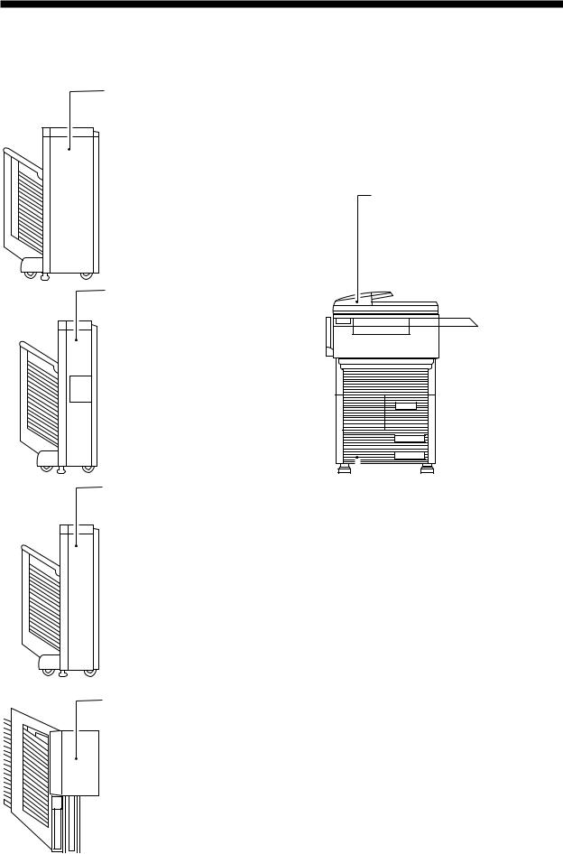
System Configuration
Stapler Sorter-E2
In addition to the functions of a 20-bin sorter, automatically staples sorted copies. Further, it swings out copies to the front for removal, and is equipped with a multiple stacking function, in which two or more sets of copies may be delivered to a single bin.
RDF-H1
Feeds originals one by one from a stack to the copyboard for copying.
Stapler Sorter-G1
In addition to the functions of a 20-bin sorter, automatically staples sorted copies.
Sorter-G1 |
|
|
Is a 20-bin sorter capable of automatic |
|
NP6045 |
sorting and grouping. |
|
|
|
|
Sorter-E1
Is a 20-bin sorter capable of automatic sorting and grouping.
COPYRIGHT © 1997 CANON INC. |
CANON NP6045 REV.1 MAR. 1997 PRINTED IN JAPAN (IMPRIMÉ AU JAPON) |
iii |
blank page
iv

CONTENTS
CHAPTER 1 GENERAL DESCRIPTION
I. |
FEATURES......................................... |
1-1 |
|
1. Cross Section of the Body ....... |
1-11 |
|
II. |
SPECIFICATIONS .............................. |
1-2 |
IV. |
OPERATIONS .................................... |
1-12 |
|
|
1. |
Type.......................................... |
1-2 |
|
A. Control Panel................................. |
1-12 |
|
2. |
System ..................................... |
1-2 |
|
B. Special Features Mode ................. |
1-13 |
|
3. |
Performance............................. |
1-3 |
|
C. User Mode..................................... |
1-14 |
|
4. |
Others....................................... |
1-6 |
|
1. Types of User Modes ............... |
1-14 |
III. |
NAMES OF PARTS ............................ |
1-9 |
V. |
ROUTINE WORK BY THE USER ...... |
1-18 |
|
|
A. External View................................. |
1-9 |
VI. |
IMAGE FORMATION.......................... |
1-19 |
|
|
B. Cross Section ................................ |
1-11 |
|
A. Outline ........................................... |
1-19 |
|
CHAPTER 2 BASIC OPERATION
I. |
BASIC OPERATIONS ........................ |
2-1 |
|
|
A. Functional Construction................. |
2-1 |
|
|
B. Outline of the Electric Circuitry...... |
2-2 |
|
|
C. Basic Sequence of Operations...... |
2-4 |
|
|
1. |
Basic Sequence of Operations |
|
|
|
at Power-On (1/2)..................... |
2-4 |
|
2. |
Basic Sequence of Operations |
|
|
|
at Power-On (2/2)..................... |
2-5 |
|
3. |
Basic Sequence of Operations |
|
|
|
during Copying ......................... |
2-7 |
4. |
Basic Sequence of Operations |
|
|
for Page Separation ................. |
2-9 |
D. Main Motor (M1) Control Circuit .... |
2-11 |
|
1. |
Outline ...................................... |
2-11 |
2. |
Operations................................ |
2-11 |
3. |
Detecting an Error .................... |
2-12 |
E. Inputs to the DC Controller............ |
2-13 |
|
F. Outputs from the DC Controller..... |
2-21 |
|
G. Inputs to and Outputs from the |
|
|
Options .......................................... |
2-33 |
|
CHAPTER 3 EXPOSURE SYSTEM
I. |
BASIC OPERATIONS ........................ |
3-1 |
|
5. |
Scanner Motor (M3) Control |
|
|
|
A. Varying the Reproduction Ratio..... |
3-1 |
|
|
Circuit ....................................... |
3-11 |
|
II. |
LENS DRIVE MECHANISM ............... |
3-2 |
IV. |
OTHERS............................................. |
3-13 |
||
|
A. Moving the Lens ............................ |
3-2 |
|
A. Detecting the Size of Originals...... |
3-13 |
||
|
1. |
Outline ...................................... |
3-2 |
|
1. |
Outline ...................................... |
3-13 |
|
2. |
Moving the Lens....................... |
3-3 |
|
2. |
Operation.................................. |
3-14 |
|
3. |
Controlling the Lens Motors ..... |
3-3 |
|
3. |
Sizes of Originals ..................... |
3-15 |
|
4. |
Moving the Lens....................... |
3-4 |
V. |
DISASSEMBLY AND ASSEMBLY...... |
3-17 |
|
III. |
SCANNER DRIVE MECHANISM ....... |
3-6 |
|
A. Scanner Drive System................... |
3-17 |
||
|
A. Driving the Scanner....................... |
3-6 |
|
1. |
Removing the Scanner Drive |
|
|
|
1. |
Outline ...................................... |
3-6 |
|
|
Assembly Motor........................ |
3-17 |
|
2. |
Relationship between Scanner |
|
|
2. |
Outline of the Scanner Drive |
|
|
|
Sensor and Signals .................. |
3-7 |
|
|
Cable ........................................ |
3-19 |
|
3. |
Basic Sequence of Operations |
|
|
3. |
Removing the Scanner Drive |
|
|
|
for Scanner Movement............. |
3-8 |
|
|
Cable ........................................ |
3-20 |
|
4. |
Sequence of Operations for |
|
|
4. |
Adjusting the Tension of the |
|
|
|
Scanner Movement (page |
|
|
|
Scanner Drive System ............. |
3-22 |
|
|
separation) ............................... |
3-9 |
|
5. |
Positioning the Mirror ............... |
3-23 |
COPYRIGHT © 1997 CANON INC. |
CANON NP6045 REV.1 MAR. 1997 PRINTED IN JAPAN (IMPRIMÉ AU JAPON) |
v |

6. |
Adjusting the Position of the |
|
4. |
Removing the Lens X Direction |
|
|
Scanner .................................... |
3-24 |
|
Drive Motor............................... |
3-29 |
B. Lens Drive Assembly..................... |
3-25 |
5. |
Attaching the Lens X Direction |
|
|
1. |
Removing the Lens Y Direction |
|
|
Drive Belt.................................. |
3-30 |
|
Drive Motor............................... |
3-25 |
6. |
Attaching the Light-Blocking |
|
2. |
Removing the Lens Stage |
|
|
Belt ........................................... |
3-30 |
|
Temporarily ............................... |
3-27 |
7. |
When Replacing the Light- |
|
3. |
Installing the Light-Blocking |
|
|
Blocking Belt............................. |
3-31 |
|
Belt ........................................... |
3-28 |
|
|
|
CHAPTER 4 IMAGE FORMATION SYSTEM
I. |
PROCESSES ..................................... |
4-1 |
|
6. |
Controlling the Activation in |
|
|
|
A. Controlling the Surface Potential |
|
|
|
Book Frame Erasing Mode ...... |
4-18 |
|
|
of the Drum.................................... |
4-1 |
|
7. |
Controlling the Activation in |
|
|
|
1. |
Outline ...................................... |
4-1 |
|
|
Hole Image Erasing Mode........ |
4-19 |
|
2. |
Control Method......................... |
4-2 |
|
8. |
Controlling the Activation of |
|
|
3. |
Potential Measurement Circuit .4-5 |
|
|
AE Mode................................... |
4-19 |
|
|
B. Controlling the Scanning Lamp |
|
|
F. Drum Heater Circuit....................... |
4-20 |
||
|
Intensity ......................................... |
4-6 |
|
1. |
Outline ...................................... |
4-20 |
|
|
1. |
Outline ...................................... |
4-6 |
|
2. |
Idle Rotation of the |
|
|
2. |
Operations................................ |
4-6 |
|
|
Photosensitive Drum and the |
|
|
3. |
Automatic Exposure Control |
|
|
|
Developing Cylinder ................. |
4-22 |
|
|
(AE) .......................................... |
4-7 |
|
G. Cleaning the Primary Charging |
|
|
|
4. |
Check Points ............................ |
4-9 |
|
Wire ............................................... |
4-23 |
|
|
C. Controlling the Primary/Transfer |
|
|
1. |
Outline ...................................... |
4-23 |
|
|
Corona Current.............................. |
4-10 |
|
2. |
Operation of the Primary |
|
|
|
1. |
Outline ...................................... |
4-10 |
|
|
Charging Wire Cleaning Wire... |
4-23 |
|
2. |
Controlling the Primary |
|
|
H. Cleaning the Pre-Transfer, |
|
|
|
|
Corona Current......................... |
4-10 |
|
Transfer, and Separation |
|
|
|
3. |
Controlling the Transfer |
|
|
Charging Wires Automatically ....... |
4-24 |
|
|
|
Corona Current......................... |
4-11 |
II. |
DEVELOPING ASSEMBLY AND |
|
|
|
D. Controlling the Separation/Pre- |
|
|
CLEANING ASSEMBLY ..................... |
4-26 |
||
|
Transfer Corona Current ............... |
4-13 |
|
A. Outline ........................................... |
4-26 |
||
|
1. |
Outline ...................................... |
4-13 |
|
B. Detecting the Toner Level and |
|
|
|
2. |
Turning ON and OFF the |
|
|
Controlling the Supply Operation .. |
4-27 |
|
|
|
Separation/ Pre-Transfer |
|
|
C. Controlling the Developing |
|
|
|
|
Corona Current......................... |
4-15 |
|
Bias/Roller Electrode..................... |
4-29 |
|
|
3. |
Separation Corona Current |
|
|
1. |
Outline ...................................... |
4-29 |
|
|
(DC component) ....................... |
4-15 |
|
2. |
Control Timing .......................... |
4-29 |
|
4. |
Pre-Transfer Corona Current |
|
|
3. |
Developing Bias Control |
|
|
|
(DC component) ....................... |
4-15 |
|
|
Circuit ....................................... |
4-32 |
|
5. |
Controlling the DC Component |
|
|
4. |
Roller Electrode Bias Control |
|
|
|
Overcurrent of the Separation/ |
|
|
|
Circuit ....................................... |
4-33 |
|
|
Pre-Transfer Corona Current ... |
4-16 |
|
D. Detecting the Locking of the |
|
|
|
E. Controlling the Blank Exposure |
|
|
Waste Toner Feeding Screw ......... |
4-35 |
||
|
Lamp (LEDs) ................................. |
4-17 |
III. |
DISASSEMBLY AND ASSEMBLY...... |
4-36 |
||
|
1. |
Outline ...................................... |
4-17 |
|
A. Scanning Lamp ............................. |
4-36 |
|
|
2. |
Controlling the Activation in |
|
|
1. |
Removing the Scanning Lamp .4-36 |
|
|
|
Reduce Mode ........................... |
4-17 |
|
2. |
Removing the Thermal Fuse.... |
4-37 |
|
3. |
Controlling the Activation in |
|
|
B. Standard White Plate Assembly.... |
4-38 |
|
|
|
Direct Mode .............................. |
4-17 |
|
C. Pre-Exposure Lamp Unit ............... |
4-40 |
|
|
4. |
Controlling the Activation in |
|
|
1. |
Removing the Pre-Exposure |
|
|
|
Sheet Frame Erasing Mode ..... |
4-17 |
|
|
Lamp Unit ................................. |
4-40 |
|
5. |
Controlling the Activation in |
|
|
D. Blank Exposure Lamp Assembly .. |
4-41 |
|
|
|
Original Frame Erasing Mode .. |
4-18 |
|
|
|
|
vi
COPYRIGHT © 1997 CANON INC. |
CANON NP6045 REV.1 MAR. 1997 PRINTED IN JAPAN (IMPRIMÉ AU JAPON) |

1. |
Removing the Blank Exposure |
|
|
Lamp Assembly........................ |
4-41 |
E. Photosensitive Drum ..................... |
4-42 |
|
1. |
Removing the Drum Unit.......... |
4-42 |
2. |
Replacing the Drum Heater...... |
4-44 |
3. |
Installing the Photosensitive |
|
|
Drum......................................... |
4-44 |
F. Potential Sensor Assembly ........... |
4-44 |
|
1. |
Removing the Potential |
|
|
Sensor Assembly ..................... |
4-44 |
G. Primary Charging Assembly.......... |
4-45 |
|
1. |
Removing the Primary |
|
|
Charging Assembly .................. |
4-45 |
H.Pre-Transfer Charging Assembly ..4-45 1. Removing the Pre-Transfer
|
Charging Assembly .................. |
4-45 |
I. Transfer/Separation Charging |
|
|
Assembly ....................................... |
4-46 |
|
1. |
Removing the Transfer/ |
|
|
Separation Charging |
|
|
Assembly .................................. |
4-46 |
2. |
Installing the Transfer/ |
|
|
Separation Charging |
|
|
Assembly .................................. |
4-47 |
J. Charging Wire ............................... |
4-49 |
|
1. |
Outline ...................................... |
4-49 |
2.Removing the Primary Charging Assembly Wire
|
Cleaner..................................... |
4-49 |
3. |
Installing the Charging Wire ..... |
4-49 |
4. |
Routing the Grid for the |
|
|
Primary Charging Assembly..... |
4-51 |
5. Adjusting the Height of the |
|
Charging Wire .......................... |
4-53 |
6.Cleaning the Primary Charging Assembly Anti-Stray Toner
|
Sheet ........................................ |
4-54 |
K. Developing Assembly.................... |
4-55 |
|
1. |
Removing from the Developing |
|
|
Assembly .................................. |
4-55 |
2. |
Removing the Blade Unit ......... |
4-56 |
3. |
Installing the Blade................... |
4-56 |
4.Removing the Developing Cylinder and the Magnetic
Seal .......................................... |
4-57 |
5.Cleaning the Developing Assembly Anti-Stray Toner
|
Sheet ........................................ |
4-59 |
L. Hopper Assembly .......................... |
4-60 |
|
1. |
Removing the Hopper |
|
|
Assembly .................................. |
4-60 |
M. Drum Cleaner ................................ |
4-61 |
|
1. |
Construction ............................. |
4-61 |
2. |
Removing the Cleaning Blade..4-61 |
|
3. |
Installing the Cleaning Blade.... |
4-62 |
4. |
Installing the Side Seal............. |
4-63 |
5. |
Cleaning the Cleaning Side |
|
|
Scraper ..................................... |
4-63 |
N. Separation Claw/Separation |
|
|
Claw Drive Assembly .................... |
4-65 |
|
1.Removing the Separation Claw/Separation Drive
Assembly from the Drum Unit ..4-65
O. Waste Toner Feeding Assembly....4-66
CHAPTER 5 PICK-UP/FEEDING SYSTEM
I. |
PICK-UP/FEEDING SYSTEM ............ |
5-1 |
2. |
Sequence of Pick-Up |
|
|
|
A. Outline ........................................... |
5-1 |
|
Operations................................ |
5-12 |
|
II. |
PICK-UP FROM THE CASSETTE ..... |
5-3 |
B. Lifter Operations............................ |
5-13 |
||
|
A. Pick-Up Operation ......................... |
5-3 |
1. |
Operations................................ |
5-13 |
|
|
1. |
Outline ...................................... |
5-4 |
2. |
Deck Limit Detection ................ |
5-14 |
|
2. |
Sequence of Pick-Up |
|
C. Detecting Paper for the Deck ........ |
5-15 |
|
|
|
Operations................................ |
5-4 |
1. |
Detecting the Presence/ |
|
|
B. Cassette Lifter Operations............. |
5-5 |
|
Absence of Paper..................... |
5-15 |
|
|
C. Detecting the Size of Copy |
|
2. |
Detecting the Deck Size........... |
5-15 |
|
Paper in the Cassette.................... |
5-7 |
|
D. High-Speed Pick-Up...................... |
5-15 |
|
1. |
Outline ...................................... |
5-7 |
IV. |
PICK-UP FROM THE |
|
2. |
Detecting the Size of Paper ..... |
5-7 |
|
MULTIFEEDER................................... |
5-16 |
3. |
Markings on the Width Guide |
|
|
A. Pick-Up Operation ......................... |
5-16 |
|
Rail ........................................... |
5-8 |
|
B. Detecting the Size of Paper in |
|
4. |
Paper Sizes .............................. |
5-9 |
|
the Multifeeder............................... |
5-17 |
5. |
Registering Paper Width Basic |
|
|
C. Sequence of Operations |
|
|
Value......................................... |
5-10 |
|
(multifeeder) .................................. |
5-18 |
III. PICK-UP FROM THE PAPER DECK .... |
5-11 |
V. |
CONTROLLING THE |
|
|
A. Outline ........................................... |
5-11 |
|
REGISTRATION CLUTCH ................. |
5-19 |
|
1. |
Pick-Up Operations .................. |
5-12 |
VI. |
MAKING TWO-SIDED/OVERLAY |
|
|
|
|
|
COPIES (1st SIDE) ............................ |
5-20 |
COPYRIGHT © 1997 CANON INC. |
CANON NP6045 REV.1 MAR. 1997 PRINTED IN JAPAN (IMPRIMÉ AU JAPON) |
vii |
A. Two-Sided/Overlay Copy |
|
12.Internal Delivery Paper |
|
||
Operation....................................... |
5-20 |
|
Stationary Jam ......................... |
5-48 |
|
1. |
Sequence of Operations for |
|
13.Holding Tray Inlet Delay Jam ... |
5-49 |
|
|
Making Two-Sided/Overlay |
|
14.Holding Tray Inlet Stationary |
|
|
|
Copies (1st side) ...................... |
5-21 |
|
Jam........................................... |
5-49 |
B. Making Two-Sided Copies |
|
15.Holding Tray Re-Pick Up Delay |
|||
(2nd side) ...................................... |
5-22 |
|
Jam........................................... |
5-50 |
|
1. |
Sequence of Operations for |
|
16.Holding Tray Registration |
|
|
|
Making Two-Sided Copies |
|
|
Delay Jam ................................ |
5-50 |
|
(2nd side) ................................. |
5-23 |
17.Holding Tray Registration |
|
|
C. Making Overlay Copies |
|
|
Stationary Jam ......................... |
5-51 |
|
(2nd side) ...................................... |
5-24 |
18.Holding Tray Feeding 1/2 |
|
||
1. |
Outline ...................................... |
5-24 |
|
Delay Jam ................................ |
5-51 |
2. |
Outline of Operations ............... |
5-25 |
19.Holding Tray Feeding 1/2 |
|
|
3. |
Sequence of Operations for |
|
|
Stationary Jam ......................... |
5-52 |
|
Overlay Copies (2nd side)........ |
5-27 |
20.Fixing Assembly Separation |
|
|
D. Reversal Delivery .......................... |
5-28 |
|
Claw Stationary Jam ................ |
5-52 |
|
1. |
Sequence of Reversal |
|
VIII. DISASSEMBLY AND ASSEMBLY...... |
5-53 |
|
|
Delivery Operations.................. |
5-29 |
A. Multifeeder Assembly .................... |
5-53 |
|
E. Switching Paper Sizes for Two- |
|
1. |
Removing the Multifeeder |
|
|
Sided/Overlay/Reversal Delivery |
|
|
Assembly .................................. |
5-53 |
|
Copies ........................................... |
5-30 |
2. |
Removing the Pick-Up Roller ... |
5-54 |
|
1. |
Movement of the Paper Size |
|
3. |
Installing the Pick-Up Roller ..... |
5-54 |
|
Guide ........................................ |
5-30 |
4. |
Removing the Separation |
|
2. |
Movement of the Paper |
|
|
Roller ........................................ |
5-55 |
|
Jogging Plate and the Rear |
|
5. |
Removing the Feeding Roller... |
5-57 |
|
Guide Plate............................... |
5-31 |
6. |
Removing the Multifeeder |
|
3. |
Detecting Copy Paper .............. |
5-32 |
|
Paper Sensor ........................... |
5-58 |
F. Re-Pick Up from the Holding |
|
7. |
Attaching the Side Guide |
|
|
Tray................................................ |
5-33 |
|
Timing Belt for the Multifeeder |
|
|
G. Skipping......................................... |
5-34 |
|
Assembly .................................. |
5-60 |
|
1. |
Outline ...................................... |
5-34 |
8. |
Installing the Feeding Roller of |
|
2. |
Operation.................................. |
5-34 |
|
the Multifeeder.......................... |
5-60 |
3. |
Skip Mode (copying an even |
|
9. |
Adjusting the Pick-Up/Feeding |
|
|
number of originals) ................. |
5-35 |
|
Roller Pressure (multifeeder) ... |
5-61 |
4. |
Skip Mode (copying an odd |
|
10.Positioning the Pick-Up Roller |
|
|
|
number of originals) ................. |
5-37 |
|
Releasing Solenoid |
|
5. |
Reverse Delivery ...................... |
5-39 |
|
(multifeeder) ............................. |
5-61 |
VII. DETECTING JAMS ............................ |
5-40 |
B. Paper Deck Assembly ................... |
5-62 |
||
A. Outline ........................................... |
5-40 |
1. |
Removing the Paper Deck |
|
|
1. |
Registration Roller Delay Jam..5-43 |
|
Assembly from the Copier........ |
5-62 |
|
2. |
Registration Roller Stationary |
|
2. |
Removing the Lifter Cable........ |
5-63 |
|
Jam........................................... |
5-43 |
3. |
Changing the Deck Paper |
|
3. |
Pick-Up Vertical Path Feeding |
|
|
Size .......................................... |
5-68 |
|
0/1 Delay Jam .......................... |
5-44 |
4. |
Adjusting the Registration for |
|
4. |
Pick-Up Vertical Path Feeding |
|
|
the Deck ................................... |
5-70 |
|
0/1 Stationary Jam ................... |
5-44 |
C . Cassette/Paper Deck Pick-Up |
|
|
5. |
Pick-Up Vertical Path Feeding |
|
Assembly ....................................... |
5-71 |
|
|
2–4 Delay Jam ......................... |
5-45 |
1. |
Removing the Pick-Up |
|
6. |
Pick-Up Vertical Path Feeding |
|
|
Assembly from the Copier........ |
5-71 |
|
2–4 Stationary Jam .................. |
5-45 |
2. |
Removing the Pick-Up Roller ... |
5-71 |
7. |
Fixing Assembly Outlet Delay |
|
3. |
Removing the Feeding Roller... |
5-73 |
|
Jam........................................... |
5-46 |
4. |
Removing the Separation |
|
8. |
Fixing Assembly Outlet |
|
|
Roller ........................................ |
5-73 |
|
Stationary Jam ......................... |
5-46 |
5. |
Adjusting the Separation |
|
9. |
External Delivery Delay Jam .... |
5-47 |
|
Roller Pressure......................... |
5-75 |
10.External Delivery Stationary |
|
6. |
Orientation of the Separation |
|
|
|
Jam........................................... |
5-47 |
|
Roller ........................................ |
5-76 |
11.Internal Delivery Delay Jam ..... |
5-48 |
|
|
|
|
viii
COPYRIGHT © 1997 CANON INC. |
CANON NP6045 REV.1 MAR. 1997 PRINTED IN JAPAN (IMPRIMÉ AU JAPON) |
7.Orientation of the Feeding Roller of the Cassette/Deck
Pick-Up Assembly .................... |
5-76 |
8.Position of the Pick-Up Roller Releasing Solenoid of the
Deck ......................................... |
5-77 |
9.Position of the Pick-Up Roller Releasing Solenoid for the
|
Cassette ................................... |
5-77 |
10.Adjusting Registration for the |
|
|
|
Cassette ................................... |
5-77 |
D. Pick-Up Vertical Path Roller |
|
|
Assembly ....................................... |
5-78 |
|
1. |
Removing the Pick-Up Vertical |
|
|
Path Roller Assembly............... |
5-78 |
E. Registration Feeding Assembly..... |
5-79 |
|
1. |
Construction ............................. |
5-79 |
2. |
Removing the Registration |
|
|
Feeding Assembly.................... |
5-79 |
3. |
Removing the Registration |
|
|
Roller (upper rubber)................ |
5-80 |
F. Feeding Assembly......................... |
5-82 |
|
1. |
Construction ............................. |
5-82 |
2. |
Removing the Fixing/Feeding |
|
|
Unit ........................................... |
5-82 |
3. |
Removing the Feeding Belt...... |
5-83 |
G. Holding Tray Assembly.................. |
5-86 |
|
1. |
Construction ............................. |
5-86 |
2. |
Removing the Holding Tray |
|
|
Assembly from the Copier........ |
5-87 |
3. |
Removing the Holding Tray |
|
|
Re-Pick Up Assembly .............. |
5-87 |
4. |
Removing the Holding Tray |
|
|
Registration Paper Sensor ....... |
5-88 |
5. |
Removing the Re-Pick Up |
|
|
Roller ........................................ |
5-89 |
6. |
Removing the Holding Tray |
|
|
Driver PCB ............................... |
5-89 |
7. |
Removing the Holding Tray Y |
|
|
Motor ........................................ |
5-90 |
8. Removing the Y Motor Home |
|
Position Sensor ........................ |
5-92 |
9. Removing the Holding Tray |
|
Inlet Assembly .......................... |
5-92 |
10.Removing the Feeding |
|
Roller/Separation Belt |
|
Assembly .................................. |
5-94 |
11.Removing the Feeding Roller... |
5-95 |
12.Removing the Separation Belt |
|
Assembly .................................. |
5-96 |
13.Adjusting the Pressure of the |
|
Separation Roller of the |
|
Holding Tray ............................. |
5-96 |
14.Position of the Holding Tray |
|
Paper Deflecting Plate Drive |
|
Solenoid ................................... |
5-97 |
15.Removing the Side Guide |
|
Plate ......................................... |
5-97 |
16.Removing the Holding Tray X |
|
Motor ........................................ |
5-98 |
17.Removing the Holding Tray |
|
Re-Circulating Motor ................ |
5-98 |
18.Removing the Holding Tray |
|
Paper Jogging Solenoid ........... |
5-99 |
19.Installing the Holding Tray |
|
Paper Jogging Guide Plate |
|
Assembly .................................. |
5-101 |
20.Installing the Holding Tray |
|
Assembly Side Guide Plate |
|
Assembly .................................. |
5-101 |
21.Attaching the Timing Belt for |
|
the Holding Tray Assembly |
|
Paper Jogging Guide Plate ...... |
5-102 |
22.Position of the Holding Tray |
|
Paper Jogging Solenoid ........... |
5-102 |
H. Holding Tray Feeding Assembly ... |
5-103 |
1. Removing the Holding Tray |
|
Feeding Assembly from the |
|
Copier....................................... |
5-103 |
2. Removing the Sensor from the |
|
Holding Tray ............................. |
5-104 |
CHAPTER 6 FIXING SYSTEM
I. |
BASIC OPERATIONS ........................ |
6-1 |
1. |
Outline ...................................... |
6-13 |
|
A. Outline ........................................... |
6-1 |
2. |
Scanning Lamp Error |
|
|
B. Fixing Drive Assembly................... |
6-2 |
|
Activation Detection Circuit ...... |
6-14 |
|
C. Controlling the Fixing |
|
3. |
Fixing Heater Error Activation |
|
|
Temperature .................................. |
6-3 |
|
Detection Circuit ....................... |
6-15 |
|
D. Reciprocating Mechanism for |
|
II. DISASSEMBLY AND ASSEMBLY...... |
6-16 |
|
|
the Main Thermistor (TH1) ............ |
6-8 |
A. Fixing Assembly ............................ |
6-16 |
|
|
E. Reciprocating Mechanism for |
|
1. |
Construction ............................. |
6-16 |
|
the Upper Separation Claw ........... |
6-9 |
2. |
Locking Mechanism.................. |
6-16 |
|
F. Fixing Heater SSR Error |
|
3. |
Removing the Fixing Cleaning |
|
|
Detection Circuit ............................ |
6-10 |
|
Belt ........................................... |
6-17 |
|
G. Locking the Fixing/Feeding Unit.... |
6-12 |
4. |
Installing the Fixing Cleaning |
|
|
H. Error Detection Circuit ................... |
6-13 |
|
Belt ........................................... |
6-19 |
COPYRIGHT © 1997 CANON INC. |
CANON NP6045 REV.1 MAR. 1997 PRINTED IN JAPAN (IMPRIMÉ AU JAPON) |
ix |

5. |
Removing the Upper Fixing |
|
17.Removing the Sub Thermistor |
|
|
|
Unit ........................................... |
6-20 |
|
(TH2) Unit................................. |
6-32 |
6. |
Removing the Fixing Heater..... |
6-22 |
B. Delivery Assembly ......................... |
6-33 |
|
7. |
Installing the Fixing Heater....... |
6-24 |
1. |
Construction ............................. |
6-33 |
8. |
Removing the Upper Fixing |
|
2. |
Removing the Delivery Upper |
|
|
Roller ........................................ |
6-24 |
|
Guide (fixing delivery |
|
9. |
Installing the Upper Fixing |
|
|
assembly) ................................. |
6-33 |
|
Roller ........................................ |
6-26 |
3. |
Removing the Fixing/Feeding |
|
10.Removing the Thermal Switch .6-27 |
|
Locking Assembly .................... |
6-34 |
||
11.Removing the Main Thermistor |
|
4. |
Removing the External |
|
|
|
(TH1) ........................................ |
6-27 |
|
Delivery Roller .......................... |
6-34 |
12.Removing the Lower |
|
5. |
Removing the External Delivery |
||
|
Separation Claw Assembly ...... |
6-28 |
|
Sensor and the Internal |
|
13.Removing the Lower Roller...... |
6-29 |
|
Delivery Sensor ........................ |
6-36 |
|
14.Removing the Upper |
|
6. |
Removing the Fixing Assembly |
|
|
|
Separation Claw ....................... |
6-30 |
|
Outlet Paper Sensor |
|
15.Adjusting the Nip (tightening |
|
|
Assembly .................................. |
6-36 |
|
|
the pressure adjusting nut)....... |
6-30 |
7. |
Removing the Internal Delivery |
|
16.Adjusting the Fixing Clutch....... |
6-31 |
|
Roller ........................................ |
6-37 |
|
CHAPTER 7 EXTERNALS/AUXILIARY MECHANISMS
I. |
CONTROL PANEL ............................. |
7-1 |
1. |
Removing the Front Door |
|
|
|
A. Outline ........................................... |
7-1 |
|
Switch Assembly ...................... |
7-26 |
|
|
B. Operation....................................... |
7-1 |
2. |
Removing the Multifeeder |
|
|
|
1. |
Data Communication ................ |
7-1 |
|
Door Switch Assembly ............. |
7-27 |
|
2. |
LCD Processing ....................... |
7-2 |
3. |
Installing the Drum Heater |
|
|
3. |
LCD Contrast Automatic |
|
|
Switch ....................................... |
7-27 |
|
|
Adjustment ............................... |
7-3 |
D. Fan Unit ......................................... |
7-28 |
|
|
4. |
Touch Switch Input ................... |
7-4 |
1. |
Removing the Scanner |
|
II. |
FANS |
.................................................. |
7-5 |
|
Cooling Fan .............................. |
7-28 |
III. |
POWER ...............................SUPPLY |
7-8 |
2. |
Removing the Air Exhaust |
|
|
|
A. Outline ................of Power Supply |
7-8 |
|
Fan ........................................... |
7-28 |
|
|
B. Power .....................Supply Circuit |
7-9 |
3. |
Removing the Fixing Air |
|
|
|
C. Power Supply for Date/Time |
|
|
Exhaust Fan ............................. |
7-29 |
|
|
Display........................................... |
7-11 |
4. |
Removing the Developing |
|
|
IV. |
DISASSEMBLY ......AND ASSEMBLY |
7-12 |
|
Fan ........................................... |
7-29 |
|
|
A. External .............................Covers |
7-12 |
5. |
Removing the Cleaner Fan ...... |
7-30 |
|
|
1. ......... |
Removing the Front Door |
7-13 |
6. |
Removing the Feeding Fan...... |
7-31 |
|
2. |
Removing the Inside Upper |
|
E. Removing the Counter Assembly..7-31 |
||
|
........................................ |
Cover |
7-15 |
F. Main Motor Assembly.................... |
7-32 |
|
|
3. |
Removing the Fixing/Feeding |
|
1. |
Removing the Main Motor ........ |
7-32 |
|
....................... |
Unit Front Cover |
7-15 |
G. Fixing/Waste Toner Drive |
|
|
|
4. ........ |
Removing the Rear Cover |
7-16 |
Assembly ....................................... |
7-32 |
|
|
5. |
Sliding Out the Hopper |
|
1. |
Construction ............................. |
7-32 |
|
.................................. |
Assembly |
7-16 |
2. |
Removing the Waste Toner |
|
|
6. ...... |
Removing the Process Unit |
7-17 |
|
Bottle ........................................ |
7-33 |
|
7. ........ |
Installing the Process Unit |
7-19 |
3. |
Removing the Fixing/Waste |
|
|
B. Control .................................Panel |
7-20 |
|
Toner Drive Assembly .............. |
7-33 |
|
|
1. |
Removing the Control Panel |
|
H. Drive Assembly (drum/ |
|
|
|
........................ |
from the Copier |
7-20 |
developing assembly).................... |
7-35 |
|
|
2. |
Removing the Control Panel |
|
1. |
Construction ............................. |
7-35 |
|
.......................................... |
PCB |
7-24 |
2. |
Removing the Drive Assembly .7-35 |
|
|
3. ...... |
Removing the Touch Panel |
7-24 |
I. Vertical Path Drive Assembly ........ |
7-36 |
|
|
4. |
Removing the Control Panel |
|
1. |
Construction ............................. |
7-36 |
|
................................. |
CPU PCB |
7-25 |
2. |
Removing the Vertical Path |
|
|
C. Door ..................Switch Assembly |
7-26 |
|
Drive Assembly ........................ |
7-37 |
|
x
COPYRIGHT © 1997 CANON INC. |
CANON NP6045 REV.1 MAR. 1997 PRINTED IN JAPAN (IMPRIMÉ AU JAPON) |

J. Pick-Up Drive Assembly................ |
7-39 |
N. Attaching the Drive Belt................. |
7-45 |
||
1. |
Construction ............................. |
7-39 |
O. DC Controller PCB ........................ |
7-46 |
|
2. |
Removing the Pick-Up Drive |
|
1. |
Removing the DC Controller |
|
|
Assembly .................................. |
7-39 |
|
PCB .......................................... |
7-46 |
K. Duplexing Unit Drive 1 Assembly.. |
7-40 |
2. |
Points to Note When Replacing |
||
1. |
Construction ............................. |
7-40 |
|
the DC Controller PCB ............. |
7-46 |
2. |
Removing the Duplexing Unit |
|
P. DC Power Supply Assembly ......... |
7-47 |
|
|
Drive 1 Assembly ..................... |
7-40 |
1. |
Removing the DC Power |
|
L. Lifter Drive Assembly .................... |
7-41 |
|
Supply Assembly...................... |
7-47 |
|
1. |
Construction ............................. |
7-41 |
Q. High-Voltage Transformer |
|
|
2. |
Removing the Lifter Assembly .7-42 |
Assembly ....................................... |
7-48 |
||
M. Cassette Pick-Up Drive |
|
1. |
Remove the High-Voltage |
|
|
Assembly ....................................... |
7-43 |
|
Transformer Assembly ............. |
7-48 |
|
1. |
Construction ............................. |
7-43 |
R. Power Supply Input Assembly ...... |
7-49 |
|
2. |
Removing the Cassette |
|
|
|
|
|
Pick-Up Drive Assembly........... |
7-43 |
|
|
|
CHAPTER 8 INSTALLATION
I. |
SELECTING THE SITE ...................... |
8-1 |
|
F. Checking the Developing |
|
II. |
UNPACKING AND INSTALLATION.... |
8-3 |
|
Assembly ....................................... |
8-17 |
|
A. Unpacking...................................... |
8-4 |
|
G. Installing the Pick-Up Assembly.... |
8-19 |
|
B. Installing the Scanner.................... |
8-6 |
|
H. Supplying Toner............................. |
8-20 |
|
C. Installing the Fixing Assembly....... |
8-7 |
|
I. Setting Images/Functions and |
|
|
D. Installing the AP Kit and the |
|
|
User Mode..................................... |
8-24 |
|
Charging Assembly ....................... |
8-9 |
III. |
RELOCATING THE MACHINE........... |
8-28 |
|
E. Installing the Copy Tray................. |
8-15 |
IV. |
INSTALLING THE CONTROL |
|
|
1. Replacing the Delivery Gear .... |
8-15 |
|
CARD V .............................................. |
8-29 |
|
2. Replacing the Leaf Springs of |
|
|
|
|
|
the Delivery Roller.................... |
8-16 |
|
|
|
CHAPTER 9 MAINTENANCE AND SERVICING
I. |
PERIODICALLY REPLACED PARTS ... |
9-1 |
III. |
SCHEDULED SERVICING................. |
9-4 |
II. |
CONSUMABLES AND DURABLES ... |
9-2 |
IV. |
SCHEDULED SERVICING CHART ... |
9-6 |
|
A. Copier ............................................ |
9-2 |
|
A. Copier ............................................ |
9-6 |
|
B. RDF-H1 ......................................... |
9-3 |
|
B. RDF-H1 ......................................... |
9-8 |
CHAPTER 10 TROUBLESHOOTING
I. |
MAINTENANCE AND INSPECTION .. |
10-3 |
2. |
Adjusting the Leading Edge |
|
|
A. Image Adjustment Basic |
|
|
Non-Image Width |
|
|
Procedure.................................... |
10-3 |
|
(registration) ........................... |
10-5 |
|
B. Points to Note for Scheduled |
|
3. |
Adjusting the Left/Right |
|
|
Servicing...................................... |
10-4 |
|
Registration (paper deck and |
|
II. |
STANDARDS AND |
|
|
cassette position) ................... |
10-5 |
|
ADJUSTMENTS ............................... |
10-5 |
4. |
Adjusting the Left/Right |
|
|
A. Image Adjustment ....................... |
10-5 |
|
Registration (holding tray |
|
|
1. Adjusting the Leading Edge |
|
|
position; 2nd side of a two- |
|
|
Margin .................................... |
10-5 |
|
sided/overlay copy) ................ |
10-7 |
COPYRIGHT © 1997 CANON INC. |
CANON NP6045 REV.1 MAR. 1997 PRINTED IN JAPAN (IMPRIMÉ AU JAPON) |
xi |
5. |
Adjusting the Left/Right |
|
11.Adjusting the Pick-Up Roller |
|
|
|
Margin .................................... |
10-8 |
|
Releasing Solenoid |
|
6. |
AE Auto Adjustment ............... |
10-8 |
|
(multifeeder) ........................... |
10-27 |
7. |
Adjusting the AE Slope .......... |
10-9 |
12.Routing the Timing Belt for the |
||
B. Exposure System ........................ |
10-10 |
|
Multifeeder Assembly Side |
|
|
1. |
Adjusting the Scanner Home |
|
|
Guide...................................... |
10-27 |
|
Position................................... |
10-10 |
13.Adjusting the Position of the |
|
|
2. |
Routing the Scanner Drive |
|
|
Delivery Paper Deflecting |
|
|
Cable ...................................... |
10-11 |
|
Drive Solenoid........................ |
10-28 |
3. |
Adjusting the Tension of the |
|
14.Adjusting the Position of the |
|
|
|
Scanner Cable ....................... |
10-12 |
|
Holding Tray Paper Deflecting |
|
4. |
Adjusting the Mirror Position .. |
10-12 |
|
Plate Drive Solenoid............... |
10-28 |
5. |
Cleaning the Mirror (No. 5 |
|
15.Installing the Holding Tray |
|
|
|
mirror)..................................... |
10-13 |
|
Assembly Side Guide |
|
6. |
Installing the Light-Blocking |
|
|
Assembly................................ |
10-29 |
|
Belts ....................................... |
10-13 |
16.Installing the Holding Tray |
|
|
7. |
Installing the Lens X |
|
|
Paper Jogging Guide |
|
|
Direction Drive Belt ................ |
10-14 |
|
Assembly................................ |
10-29 |
C. Image Formation System ............ |
10-15 |
17.Installing the Timing Belt for |
|
||
1. |
Routing the Grid for the |
|
|
the Holding Tray Assembly |
|
|
Primary Charging Assembly... |
10-15 |
|
Paper Jogging Guide Plate .... |
10-30 |
2. |
Adjusting the Height of the |
|
18.Adjusting the Position of the |
|
|
|
Charging Wire ........................ |
10-17 |
|
Holding Tray Paper Jogging |
|
3. |
Adjusting the Blank Exposure |
|
|
Solenoid ................................. |
10-30 |
|
Lamp ...................................... |
10-18 |
19.Installing the Drive Belt .......... |
10-31 |
|
4. |
Position of the Roller |
|
E. Fixing System.............................. |
10-32 |
|
|
Electrode ................................ |
10-19 |
1. |
Points to Note When |
|
5. |
Position of the Side Seal in |
|
|
Handling the Fixing Heater .... |
10-32 |
|
the Cleaning Assembly .......... |
10-19 |
2. |
Position of the Fixing |
|
6. |
Cleaning the Cleaner Side |
|
|
Assembly Paper Guide .......... |
10-32 |
|
Scraper................................... |
10-19 |
3. |
Adjusting the Pressure of the |
|
D. Pick-Up/Feeding System............. |
10-21 |
|
Lower Roller (nip)................... |
10-33 |
|
1. |
Orientation of the Pick-Up |
|
4. |
Adjusting the Fixing Clutch .... |
10-34 |
|
Roller (cassette/deck) ............ |
10-21 |
F. Electrical System......................... |
10-35 |
|
2. |
Orientation of the Separation |
|
1. |
When Replacing the DC |
|
|
Roller (cassette/deck) ............ |
10-22 |
|
Controller PCB ....................... |
10-35 |
3. |
Orientation of the Feeding |
|
2. |
Checking the Surface |
|
|
Roller (cassette/deck) ............ |
10-22 |
|
Potential Control System........ |
10-35 |
4. |
Orientation of the Pick-Up |
|
3. |
Checking the Potential |
|
|
Roller (multifeeder)................. |
10-23 |
|
Control System....................... |
10-39 |
5. |
Orientation of the Feeding |
|
4. |
Potential Control System |
|
|
Roller (multifeeder)................. |
10-24 |
|
Conversion Table ................... |
10-41 |
6. |
Adjusting the Pressure of the |
|
5. |
Checking the Environment |
|
|
Separation Roller |
|
|
Sensor .................................... |
10-46 |
|
(cassette/deck) ....................... |
10-24 |
6. |
Checking the |
|
7. |
Adjusting the Pressure of the |
|
|
Photointerrupters.................... |
10-46 |
|
Separation Roller |
|
7. |
Registering the Cassette/ |
|
|
(holding tray) .......................... |
10-25 |
|
Multifeeder Paper Width |
|
8. |
Adjusting the Pressure of the |
|
|
Basic Value (]4]) .................. |
10-53 |
|
Pick-Up/Feeding Roller |
|
III. TROUBLESHOOTING IMAGE |
|
|
|
(multifeeder) ........................... |
10-25 |
FAULTS ............................................ |
10-54 |
|
9. |
Positioning the Pick-Up Roller |
A. Making Initial Checks .................. |
10-54 |
||
|
Releasing Solenoid |
|
1. |
Site of Installation................... |
10-54 |
|
(cassette)................................ |
10-26 |
2. |
Checking the Originals ........... |
10-54 |
10.Adjusting the Position of the |
|
3. |
Copyboard Cover, Copyboard |
|
|
|
Pick-Up Roller Releasing |
|
|
Glass, and Standard White |
|
|
Solenoid (deck) ...................... |
10-26 |
|
Plate ....................................... |
10-54 |
|
|
|
4. |
Charging Assemblies ............. |
10-54 |
xii
COPYRIGHT © 1997 CANON INC. |
CANON NP6045 REV.1 MAR. 1997 PRINTED IN JAPAN (IMPRIMÉ AU JAPON) |
5. |
Checking the Developing |
|
|
Assembly................................ |
10-55 |
6. |
Checking the Paper................ |
10-55 |
7. |
Checking the Periodically |
|
|
Replaced Parts....................... |
10-55 |
8. |
Others..................................... |
10-55 |
B. Image Fault Samples .................. |
10-58 |
|
C. Troubleshooting Image Faults..... |
10-59 |
|
1. |
The copy is too light. |
|
|
(halftone area only) ................ |
10-59 |
2. |
The copy is too light. (solid |
|
|
black also) .............................. |
10-60 |
3. |
The copy is too light. (overall, |
|
|
considerably) .......................... |
10-60 |
4. |
The copy has uneven density. |
|
|
(darker at front) ...................... |
10-62 |
5. |
The copy has uneven density. |
|
|
(lighter at front)....................... |
10-62 |
6. |
The copy is foggy. (overall) .... |
10-63 |
7. |
The copy has vertical |
|
|
fogging.................................... |
10-64 |
8. |
The copy has black lines. |
|
|
(vertical, fuzzy, thick).............. |
10-64 |
9. |
The copy has black lines. |
|
|
(vertical, thin).......................... |
10-65 |
10.The copy has white spots. |
|
|
|
(vertical).................................. |
10-66 |
11.The copy has white lines. |
|
|
|
(vertical).................................. |
10-66 |
12.The copy has white spots. |
|
|
|
(horizontal) ............................. |
10-68 |
13.The back of the copy is |
|
|
|
soiled. ..................................... |
10-69 |
14.The copy has fixing faults. ..... |
10-70 |
|
15., 16., 17. The copy has |
|
|
|
leading edge displacement. ... |
10-71 |
18.The copy has a blurred or |
|
|
|
fuzzy image. ........................... |
10-72 |
19.The copy has horizontal |
|
|
|
fogging.................................... |
10-73 |
20.The copy has poor |
|
|
|
sharpness............................... |
10-73 |
21.The copy is blank. .................. |
10-74 |
|
22.The copy is completely black... |
10-74 |
|
IV. TROUBLESHOOTING |
|
|
MALFUNCTIONS ............................. |
10-75 |
|
A. Troubleshooting Malfunctions ..... |
10-75 |
|
1. |
E000 ....................................... |
10-75 |
2. |
E001 ....................................... |
10-76 |
3. |
E002 ....................................... |
10-77 |
4. |
E003 ....................................... |
10-77 |
5. |
E004 ....................................... |
10-77 |
6. |
E005 ....................................... |
10-78 |
7. |
E006 ....................................... |
10-78 |
8. |
E010 ....................................... |
10-78 |
9. |
E013 ....................................... |
10-79 |
10.E015 ....................................... |
10-80 |
|
11.E020 ....................................... |
10-81 |
|
12.E030 (The total copy counter |
|
fails to operate.) ..................... |
10-82 |
13.E031 (The option counter has |
|
an open circuit.)...................... |
10-82 |
14.E050 ....................................... |
10-83 |
15.E051 ....................................... |
10-83 |
16.E202 (Locks the keys but |
|
does not indicate a code.)...... |
10-83 |
17.E203 ....................................... |
10-84 |
18.E204 (Locks the keys but |
|
does not indicate a code.)...... |
10-84 |
19.E210 (The lens X direction |
|
drive system has an error.) .... |
10-84 |
20.E212 (The lens Y direction |
|
drive system has an error.) .... |
10-84 |
21.E240 ....................................... |
10-85 |
22.E243 ....................................... |
10-85 |
23.E710/E711.............................. |
10-85 |
24.E712 ....................................... |
10-85 |
25.E713 ....................................... |
10-86 |
26.E800 ....................................... |
10-86 |
27 E802 ....................................... |
10-87 |
28.AC power is absent................ |
10-88 |
29.DC power is absent................ |
10-89 |
30.Pick-up fails............................ |
10-90 |
31.The deck lifter fails to move |
|
up. .......................................... |
10-91 |
32.Pick-up fails. (cassette |
|
pick-up)................................... |
10-92 |
33.The lifter fails to move up. |
|
(cassette pick-up)................... |
10-94 |
34.Pick-up fails. (multifeeder)...... |
10-95 |
35.The vertical path roller fails |
|
to rotate. ................................. |
10-96 |
36.The registration roller fails |
|
to rotate. ................................. |
10-96 |
37.The scanner fails to rotate |
|
forward. .................................. |
10-97 |
38.The scanner fails to move in |
|
reverse. .................................. |
10-97 |
39.The blank exposure lamp fails |
|
to turn ON............................... |
10-98 |
40.The pre-exposure lamp fails |
|
to turn ON............................... |
10-98 |
41.The pre-exposure lamp fails |
|
to turn ON............................... |
10-99 |
42.The hopper motor (M10) fails |
|
to operate. .............................. |
10-100 |
43.The hopper motor (M11) fails |
|
to operate. .............................. |
10-101 |
44.The drum heater fails to |
|
operate ................................... |
10-101 |
45.The lens fails to move. ........... |
10-102 |
46.The Add Toner indicator fails |
|
to turn ON............................... |
10-103 |
47.The Add Toner message fails |
|
to turn OFF. ............................ |
10-103 |
48.The Control Card Set |
|
indicator fails to turn ON. ....... |
10-104 |
COPYRIGHT © 1997 CANON INC. |
CANON NP6045 REV.1 MAR. 1997 PRINTED IN JAPAN (IMPRIMÉ AU JAPON) |
xiii |

49.The Control Card Set |
|
indicator fails to turn OFF. ...... |
10-104 |
50.Paper jams at the fixing |
|
assembly inlet. ....................... |
10-104 |
51.The Add Paper indicator fails |
|
to turn OFF. ............................ |
10-104 |
52.The fixing heater fails to turn |
|
ON. ......................................... |
10-105 |
V.TROUBLESHOOTING FEEDING
PROBLEMS...................................... |
10-106 |
|
A. Copy Paper Jams........................ |
10-106 |
|
1. |
Pick-up assembly ................... |
10-107 |
2. |
Separation/feeding assembly.10-108 |
|
3. |
Fixing/delivery assembly ........ |
10-109 |
4. |
Fixing/delivery assembly |
|
|
(reversal delivery)................... |
10-109 |
5. |
Cleaning assembly................. |
10-110 |
6. |
Holding tray assembly |
|
|
(copying on 1st side of two- |
|
|
sided/overlay copy) ................ |
10-110 |
7. |
Holding tray assembly |
|
|
(re-pick up) ............................. |
10-111 |
8. |
Holding tray assembly |
|
|
(overlay re-pick up) ................ |
10-111 |
9. |
Holding tray feeding |
|
|
assembly ................................ |
10-112 |
B. Feeding Failure ........................... |
10-113 |
|
1. |
Double feeding ....................... |
10-113 |
2. |
Wrinkling................................. |
10-113 |
VI. ARRANGEMENT/FUNCTIONS OF |
|
|
THE ELECTRICAL PARTS .............. |
10-114 |
|
A. Sensors ....................................... |
10-114 |
|
B. Switches and Solenoids .............. |
10-118 |
|
C. Motors and Fans ......................... |
10-122 |
|
D. Clutches ...................................... |
10-124 |
|
E. Lamps, Heaters, and |
|
|
Photosensors .............................. |
10-126 |
|
F. PCBs ........................................... |
10-128 |
|
G. Variable Resistors, Light- |
|
|
Emitting Diodes, and Check |
|
|
Pins by PCB ................................ |
10-130 |
|
1. |
DC Controls PCB ................... |
10-130 |
2. |
AC Driver PCB ....................... |
10-133 |
3. |
DC Power Supply PCB .......... |
10-133 |
4. |
Control CPU PCB................... |
10-134 |
5. |
Holding Tray Driver PCB........ |
10-135 |
6. |
Potential Measurement PCB..10-136 |
|
7. |
HVT1 PCB.............................. |
10-137 |
8. |
HVT2 PCB.............................. |
10-138 |
9. |
Inverter PCB........................... |
10-138 |
10.Lamp Regulator PCB ............. |
10-139 |
|
11.Counter PCB .......................... |
10-139 |
|
VII. SERVICE MODE .............................. |
10-140 |
|
A. Outline ......................................... |
10-140 |
|
B. Using Service Mode .................... |
10-140 |
|
C. Using Adjustment Mode and |
|
|
Option Setting Mode ................... |
10-141 |
|
D. Control Display Mode ( ] 1 ] ) .... |
10-142 |
|
E. I/O Display Mode ( ] 2 ] ) ........... |
10-157 |
|
F. Adjustment Mode ( ] 3 ] ) ........... |
10-193 |
|
G. Function Mode ( ] 4 ] ) ............... |
10-211 |
|
H. Options Mode ( ] 5 ] ) ................ |
10-222 |
|
I. Counter Mode ( ] 6 ] ) ................ |
10-231 |
|
VIII. SELF DIAGNOSIS ........................... |
10-237 |
|
A. Copier.......................................... |
10-237 |
|
B. RDF Self Diagnosis..................... |
10-242 |
|
C. Sorter Self Diagnosis .................. |
10-243 |
|
APPENDIX
A. GENERAL TIMING CHART .......... |
A-1 |
|
B. SIGNALS AND ABBREVIATIONS ... |
A-2 |
|
1. |
Signals...................................... |
A-2 |
2. |
Abbreviations............................ |
A-3 |
C. GENERAL CIRCUIT DIAGRAM.... |
A-5 |
|
D. RDF-H1 GENERAL CIRCUIT |
|
DIAGRAM...................................... |
A-7 |
E. SPECIAL TOOLS LIST ................. |
A-9 |
F. SOLVENTS AND OILS.................. |
A-10 |
xiv
COPYRIGHT © 1997 CANON INC. |
CANON NP6045 REV.1 MAR. 1997 PRINTED IN JAPAN (IMPRIMÉ AU JAPON) |

CHAPTER 1
GENERAL DESCRIPTION
This chapter introduces the copier's features and specifications, shows how to operate the copier, and explains how copies are made.
I. |
FEATURES......................................... |
1-1 |
|
A. Control Panel................................. |
1-12 |
II. |
SPECIFICATIONS .............................. |
1-2 |
|
B. Special Features Mode ................. |
1-13 |
III. |
NAMES OF PARTS ............................ |
1-9 |
|
C. User Mode..................................... |
1-14 |
|
A. External View................................. |
1-9 |
V. |
ROUTINE WORK BY THE USER ...... |
1-18 |
|
B. Cross Section ................................ |
1-11 |
VI. |
IMAGE FORMATION.......................... |
1-19 |
IV. |
OPERATIONS .................................... |
1-12 |
|
A. Outline ........................................... |
1-19 |
COPYRIGHT © 1997 CANON INC. |
CANON NP6045 REV. 1 MAR. 1997 PRINTED IN JAPAN (IMPRIME AU JAPON) |
blank page

CHAPTER 1 GENERAL DESCRIPTION
I. FEATURES
1.The NP6045 is capable of making as many as 45 copies (A4, horizontal) every minute.
2.It uses newly designed pick-up and feeding mechanisms so that it not only helps save space, but it also is less susceptible to jams.
3.It provides high durability and high image quality required of high-speed copying.
The use of the Canon-unique A-Si (amorphous silicon) photosensitive drum ensures high durability while the single-component toner projection mechanism promises high-quality images for a long time.
4.It is equipped with a large-size liquid crystal display, offering easy-to-understand instructions.
COPYRIGHT © 1997 CANON INC. |
CANON NP6045 REV. 1 MAR. 1997 PRINTED IN JAPAN (IMPRIME AU JAPON) |
1-1 |

CHAPTER 1 GENERAL DESCRIPTION
II. SPECIFICATIONS
1. Type
Body |
Console |
|
|
Copyboard |
Fixed |
|
|
Light source |
Halogen lamp (70 V, 265 W) |
|
|
Lens |
Zoom lens |
|
|
Photosensitive |
Amorphous silicon (ø80) |
medium |
|
|
|
2. System
Body |
Front deck paper deck type |
|
|
|
|
Copying |
Indirect electrostatographic |
|
|
|
|
Charging |
Corona |
|
|
|
|
Exposure |
Slit (moving light source) |
|
|
|
|
Copy density |
Automatic or manual |
|
adjustment |
|
|
|
|
|
Development |
Dry (toner projection) |
|
|
|
|
Pick-up |
Automatic |
2 front cassettes |
|
|
1 front paper deck |
|
|
|
|
Manual |
Multifeeder (5.5 mm deep; 50 sheets of 80 g/m2 paper) |
Transfer |
Corona |
|
|
|
|
Separation |
Corona (static separation) |
|
|
|
|
Cleaning |
Blade |
|
|
|
|
Fixing |
Heating roller (790 W + 410 W; 120 V), (1200 W; 220/240 V) |
|
|
|
|
1-2 |
COPYRIGHT © 1997 CANON INC. |
CANON NP6045 REV. 1 MAR. 1997 PRINTED IN JAPAN (IMPRIME AU JAPON) |
CHAPTER 1 GENERAL DESCRIPTION
3. Performance
Original type |
Sheet, book, 3-D object (2 kg max.) |
|
||||
|
|
|
|
|
|
|
Maximum original size |
A3/11" × 17" |
|
|
|
||
|
|
|
|
|
|
|
|
|
Direct |
1:1 |
|
|
|
|
|
|
|
|
|
|
|
|
Reduce I |
1:0.500 |
|
|
|
|
|
|
|
|
|
|
|
|
Reduce II |
1:0.707 |
|
|
|
|
|
|
|
|
|
|
|
|
Reduce III |
1:0.816 |
|
|
|
|
|
|
|
|
|
|
Copying |
|
Reduce IV |
1:0.865 |
|
|
|
ratios |
|
Enlarge I |
1:2.000 |
|
|
|
|
|
|
|
|
|
|
|
|
Enlarge II |
1:1.414 |
|
|
|
|
|
|
|
|
|
|
|
|
Enlarge III |
1:1.224 |
|
|
|
|
|
|
|
|
|
|
|
|
Enlarge IV |
1:1.154 |
|
|
|
|
|
|
|
|
||
|
|
Zoom |
1:0.490 to 2.040 (1% increments) |
|
||
|
|
|
|
|
||
Wait time |
|
5 min or less (at 20°C room temperature) |
|
|||
|
|
|
||||
First copy |
|
3.0 sec (A4, non-AE, top cassette/paper deck) |
||||
|
|
|
|
|||
Continuous copying |
999 copies max. |
|
|
|||
|
|
|
|
|
|
|
Copy size |
|
One-sided |
Metric |
A3 max. |
A6 (vertical, postcard) min. |
|
|
|
|
|
Inch |
11" × 17" max. |
STMT min. |
|
|
|
Two-sided |
Metric |
A3 max. |
A5 (horizontal) min. |
|
|
|
|
Inch |
11" × 17" max. |
STMT (horizontal) min. |
|
|
|
|
|
|
|
COPYRIGHT © 1997 CANON INC. |
CANON NP6045 REV. 1 MAR. 1997 PRINTED IN JAPAN (IMPRIME AU JAPON) |
1-3 |

CHAPTER 1 GENERAL DESCRIPTION
Copy paper type
|
|
• Plain Paper (64 to 90 g/m2) |
|
|
|
A3, B4, A4, B5, A4R, B5R, 11" × 17", LGL, LTR, LTR-R, |
|
|
|
A5, A5R, STMT, STMTR, Foolscap, GLTR, GLTR-R, KLGL, |
|
Cassette |
K-LGL-R, OFFICIO, E-OFFICIO, A-OFFICIO, B-OFFICIO, |
||
A-LTR, ALTR-R, A-LGL |
|||
|
|
• Tracing Paper* (SM-1) |
|
|
|
A3, B4, A4, B5, A4R, B5R |
|
|
|
• Colored Paper (Canon-recommended) |
|
|
|
B4, A4 |
|
|
|
• Plain Paper (64 to 90 g/m2) |
|
Paper deck |
A4, B5, LTR |
||
• Colored Paper (Canon-recommended) |
|||
|
|
||
|
|
A4 |
|
|
|
• Plain Paper (64 to 90 g/m2) |
|
|
|
A3, B4, A4, B5, A4, B5R, 11" × 17", LGL, LTR, LTR-R, |
|
|
|
STMT-R*, postcard |
|
|
|
• Tracing Paper (SM-1)* |
|
|
|
A3, B4, A4, B5, A4R, B5R |
|
Automatic |
• Transparency* (Canon-recommended) |
||
A4, LTR |
|||
|
|
• Colored Paper* (Canon-recommended) |
|
|
|
B4, A4 |
|
|
|
• Label Sheet (Canon-recommended) |
|
|
|
A4, LTR |
|
|
|
• Thick Paper* (91 to 200 g/m2) |
|
|
|
• Plain Paper* (64 to 90 g/m2) |
|
|
Automatic |
A3, B4, A4, B5, A4R, B5R, 11" × 17", LGL, LTR, LTR-R, |
|
|
A5, STMT |
||
Two- |
|
• Colored Paper (Canon-recommended) |
|
|
B4, A4 |
||
sided |
|
|
|
|
• Plain Paper* (64 to 90 g/m2) |
||
copying |
|
||
|
A3, B4, A4, B5, A4R, B5R, 11" × 17", LGL, LTR, LTR-R, |
||
|
Multifeeder |
||
|
STMT-R, A5, STMT |
||
|
|
• Colored Paper* (Canon-recommended) |
|
|
|
B4, A4 |
|
|
|
• Plain Paper* (64 to 90 g/m2) |
|
|
Automatic |
A3, B4, A4, B5, A4R, B5R, 11" × 17", LGL, LTR, LTR-R, |
|
|
A5, STMT |
||
Overlay |
|
• Colored Paper* (Canon-recommended) |
|
|
B4, A4 |
||
copying |
|
|
|
|
• Plain Paper* (64 to 90 g/m2) |
||
|
|
||
|
Multifeeder |
A3, B4, A4, B5, A4R, B5R, 11" × 17", LGL, LTR, LTR-R, |
|
|
STMT-R, A5, STMT |
||
|
|
• Colored Paper* (Canon-recommended) |
|
|
|
B4, A4 |
|
|
|
|
|
1-4 |
COPYRIGHT © 1997 CANON INC. |
CANON NP6045 REV. 1 MAR. 1997 PRINTED IN JAPAN (IMPRIME AU JAPON) |

CHAPTER 1 GENERAL DESCRIPTION
|
Claw |
|
None |
|
|
|
|
|
|
|
Cassette |
|
55 mm deep |
|
Tray |
|
|
(500 sheets each of 80 g/m2 paper) |
|
Paper deck |
|
162 mm deep |
|
|
|
|
|
||
|
|
|
(about 1500 sheets each of 80 g/m2 paper) |
|
|
Copy tray |
|
250 sheets (approx.; A3, 80 g/m2) |
|
|
Leading edge |
4.5±1.5 mm in Direct |
|
|
|
|
|
(4.5±1.5 mm in non-Direct, Overlay, Two-sided) |
|
|
|
|
|
|
|
Trailing edge |
2.0 ±1.0 mm (2.0 ±1.0 mm in non-Direct, |
||
|
|
|
Overlay, Two-sided) |
|
|
|
|
|
|
Non-image |
|
A4 horizontal, |
|
|
Left/right |
B5 horizontal, |
2.75±2.5mm |
|
|
width |
|
|||
(1st side) |
B4, A3, LTR |
|
||
|
|
|
||
|
|
horizontal |
|
|
|
|
|
|
|
|
Left/right |
A4 horizontal, |
|
|
|
B5 horizontal, |
2.75±2.5mm |
|
|
|
(2nd side) |
B4, A3, LTR |
|
|
|
|
|
||
|
|
horizontal |
|
|
|
|
|
|
|
|
|
|
Provided (2 min standard; may be changed from |
|
Auto Clear |
|
|
0 to 9 min in 1-min increments and from 0 to 50 |
|
|
|
|
sec in 10-sec increments) |
|
|
|
|
|
|
|
|
|
Provided (1 hr standard; may be changed from 0 |
|
Auto Power-Off |
|
to 2 hr; in 10-min increments up to 1st 1 hr, in 1- |
||
|
|
|
hr increments up to 24 hr) |
|
|
|
|
|
|
|
|
|
• Stapler Sorter-E2 |
• Sorter-E1 |
Accessory |
|
|
• Stapler Sorter-G1 |
• Sorter-G1 |
|
|
|
• CC-V |
• Cassette Heater |
|
|
|
|
|
COPYRIGHT © 1997 CANON INC. |
CANON NP6045 REV. 1 MAR. 1997 PRINTED IN JAPAN (IMPRIME AU JAPON) |
1-5 |

CHAPTER 1 GENERAL DESCRIPTION
4. Others
|
|
|
|
|
Front paper deck |
|
|
|
|
|
|
|
|
Temperature |
|
7.5° to 32.5°C/45.5° to 90.5°F |
|
Operating |
|
|
|
|
|
|
Humidity |
|
5 to 80% RH |
||
environment |
|
|
|
|
|
|
Atmospheric |
|
810.6hPa to 1013.3hPa (0.8 to 1.0 atm) |
||
|
|
|
|||
|
|
pressure |
|
||
|
|
|
|
||
|
|
|
|
|
|
|
|
120 V |
|
NGQ XXXXX |
|
|
|
220/240 V(ITA) |
|
FGB XXXXX |
|
|
|
220/240 V(UK) |
|
DGB XXXXX |
|
Power supply |
|
220/240 V(FRN) |
|
BGB XXXXX |
|
|
220/240 V(GER) |
|
AGB XXXXX |
||
|
|
|
|||
|
|
220/240 V(AMS) |
|
UBW XXXXX, CGB XXXXX |
|
|
|
220/240 V(CA) |
|
RBJ XXXXX |
|
|
|
220/240 V |
|
PCL XXXXX, EGB XXXXX |
|
|
|
|
|
|
|
|
|
Maximum |
|
1.5 kW or less |
|
Power |
|
|
|
|
|
|
Standby |
|
0.3 kWh or less (reference only) |
||
consumption |
|
|
|
|
|
|
Continuous |
|
1.2 kWh or less (reference only) |
||
|
|
|
|||
|
|
copying |
|
||
|
|
|
|
||
|
|
|
|
|
|
Noise |
|
Copying |
|
71 dB or less (sound power level by ISO standards) |
|
|
|
|
|
|
|
|
Standby |
|
50 dB or less (as required) |
||
|
|
|
|||
|
|
|
|
|
|
Ozone (avr over 8 hr) |
|
0.05 ppm or less |
|||
|
|
|
|
|
|
|
|
|
|
|
|
|
|
Width |
|
620 mm/24.4 in |
|
|
|
|
|
|
|
Dimensions |
|
Depth |
|
725 mm/28.5 in |
|
|
|
|
|
|
|
|
|
Height |
|
1136 mm/44.7 in |
|
|
|
|
|
|
|
Weight |
|
|
|
187 kg/412.2 lb (approx.; w/RDF) |
|
|
|
|
|
|
|
Consumables |
|
Copy paper |
|
Keep wrapped to protect against moisture. |
|
|
|
|
|
|
|
|
Toner |
|
Avoid direct sunshine, and store at 40°C, 85% or less. |
||
|
|
|
|||
|
|
|
|
|
|
1-6 |
COPYRIGHT © 1997 CANON INC. |
CANON NP6045 REV. 1 MAR. 1997 PRINTED IN JAPAN (IMPRIME AU JAPON) |

CHAPTER 1 GENERAL DESCRIPTION
Ratio |
Size |
Copy size |
Copies/min |
||||
|
|
|
|
|
|
|
|
|
|
|
|
A3(297 × 420mm) |
A3 |
24 |
|
|
|
|
|
|
|
|
|
|
|
|
|
A4(210 × 297mm) |
A4 |
45 |
|
|
|
|
|
|
|
|
|
Direct |
B4(257 × 364mm) |
B4 |
30 |
||||
|
|
|
|||||
B5(182 × 257mm) |
B5 |
45 |
|||||
|
|
|
|
||||
|
|
|
|
|
|
|
|
|
|
|
|
A4R(297 × 210mm) |
A4R |
35 |
|
|
|
|
|
|
|
|
|
|
|
|
|
B5R(257 × 182mm) |
B5R |
39 |
|
|
|
|
|
|
|
|
|
|
|
I |
A3 → 5R |
A5R |
44 |
||
|
|
(50%) |
|
||||
|
|
|
|
|
|||
|
|
|
|
|
|
|
|
|
|
|
|
A3 → 4R |
A4R |
35 |
|
|
|
II |
|
|
|
|
|
|
|
B4 → B5R |
B5R |
39 |
|||
|
|
(70%) |
|
||||
|
|
|
|
|
|||
Reduce |
|
A4 → A5 |
A5 |
45 |
|||
|
|||||||
|
|
|
|
|
|
||
|
|
III |
B4 → A4R |
A4R |
35 |
||
|
|
(81%) |
|
||||
|
|
|
|
|
|||
|
|
|
|
|
|
||
|
|
IV |
A3 → B4 |
B4 |
30 |
||
|
(86%) |
|
|
|
|
||
|
A4 → B5 |
B5 |
45 |
||||
|
|
|
|
|
|
||
|
|
I |
A5R → A3 |
A3 |
23 |
||
|
|
(200%) |
|
||||
|
|
|
|
|
|||
|
|
|
|
|
|
|
|
|
|
|
|
A4R → A3 |
A3 |
24 |
|
|
|
II |
|
|
|
|
|
|
|
B5R → B4 |
B4 |
29 |
|||
|
|
(141%) |
|
||||
|
|
|
|
|
|||
Enlarge |
|
A5 → A4 |
A4 |
45 |
|||
|
|||||||
|
|
|
|
|
|
||
|
|
III |
A4R → B4 |
B4 |
30 |
||
|
|
(122%) |
|
||||
|
|
|
|
|
|||
|
|
|
|
|
|
||
|
|
IV |
B4 → A3 |
A3 |
24 |
||
|
(115%) |
|
|
|
|
||
|
B5 → A4 |
A4 |
45 |
||||
|
|
|
|
|
|
|
|
Table 1-201 Copying Speed (copier only)
COPYRIGHT © 1997 CANON INC. |
CANON NP6045 REV. 1 MAR. 1997 PRINTED IN JAPAN (IMPRIME AU JAPON) |
1-7 |

CHAPTER 1 GENERAL DESCRIPTION
|
Ratio |
Size |
Copy paper size |
Copies/min |
||||
|
|
|
|
|
|
|
|
|
|
|
|
|
|
LTR |
LTR |
45 |
|
|
|
|
|
|
|
|
|
|
|
|
|
|
|
11” × 17” |
11” × 17” |
24 |
|
|
|
|
|
|
|
|
|
|
Direct |
LGL |
LGL |
30 |
|||||
|
|
|
||||||
LTRR |
LTRR |
37 |
||||||
|
|
|
|
|
||||
|
|
|
|
|
|
|
|
|
|
|
|
|
|
STMT/STMTR |
STMT/STMTR |
45 |
|
|
|
|
|
|
|
|
|
|
|
|
|
|
|
|
|
|
|
|
|
|
I |
11” × 17” → STMTR |
STMTR |
43 |
||
|
|
(50%) |
|
|
|
|
||
|
|
|
|
|
||||
|
|
|
|
|
|
|
|
|
|
|
|
II |
11” × 17” → LTRR |
LTRR |
37 |
||
Reduce |
|
(64.7%) |
|
|
|
|
||
|
|
|
|
|
|
|
||
|
|
III |
11” × 15” → LTRR |
LTRR |
30 |
|||
|
|
|
||||||
|
|
(73.3%) |
|
|
|
|
||
|
|
|
|
|
||||
|
|
|
|
|
|
|
||
|
|
|
I |
STMR → 11” × 17” |
11” × 17” |
24 |
||
|
|
(200%) |
|
|
|
|
||
|
|
|
|
|
|
|
||
|
|
|
II |
LTRR → 11” × 17” |
11” × 17” |
24 |
||
|
|
(129.4%) |
|
|
|
|
||
Enlarge |
|
|
|
|
|
|
|
|
|
|
III |
LGL → 11” × 17” |
11” × 17” |
24 |
|||
|
|
|
||||||
|
|
(121.4%) |
|
|
|
|
||
|
|
|
|
|
|
|
|
|
Table 1-202 Copying Speed (copier only)
Specifications are subject to change without notice.
1-8 |
COPYRIGHT © 1997 CANON INC. |
CANON NP6045 REV. 1 MAR. 1997 PRINTED IN JAPAN (IMPRIME AU JAPON) |
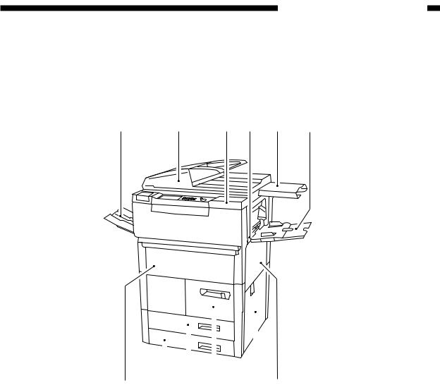
CHAPTER 1 GENERAL DESCRIPTION
III. NAMES OF PARTS
A. External View
qw e r t y
|
|
|
|
|
|
|
|
|
|
|
|
|
|
|
|
|
|
|
|
|
|
|
|
!2 !1 !0 o |
i u |
||||
q Copy tray |
u Upper right door |
||||
w RDF |
i Lower right door |
||||
e Toner supply mouth |
o Paper deck |
||||
r Power switch |
!0Cassette 3 |
||||
t Original tray/manual holder |
!1Cassette 4 |
||||
y Multifeeder |
!2Front door |
||||
Figure 1-301
COPYRIGHT © 1997 CANON INC. |
CANON NP6045 REV. 1 MAR. 1997 PRINTED IN JAPAN (IMPRIME AU JAPON) |
1-9 |
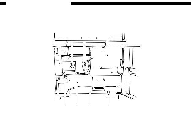
CHAPTER 1 GENERAL DESCRIPTION
@1 @2 @3 |
@4 |
||||
|
|
|
|
|
|
|
|
|
|
|
|
|
|
|
|
|
|
@8 @7 @6 @5
@1Fixing/feeding assembly @2Fixing assembly knob @3Fixing/feeding assembly releasing
lever @4Toner hopper
@5Holding tray feeding knob @6Holding tray feeding assembly @7Holding tray assembly @8Holding tray knob
Figure 1-302
1-10 |
COPYRIGHT © 1997 CANON INC. |
CANON NP6045 REV. 1 MAR. 1997 PRINTED IN JAPAN (IMPRIME AU JAPON) |

CHAPTER 1 GENERAL DESCRIPTION
B. Cross Section
1. Cross Section of the Body
q w e r t y u i o !0 !1 !2 !3 !4 !5!7!6
@9 |
@8 @7 @6 |
@5 |
@4@3 |
@2 |
@1 @0 |
!9 |
q No. 3 mirror |
!2Primary charging |
|
@2Registration roller |
|||
w No. 2 mirror |
assembly |
|
@3Transfer/separation |
|||
e Heat absorption |
!3Potential sensor |
|
|
assembly |
|
|
glass |
!4No. 6 mirror |
|
@4Feeding belt |
|
||
r Scanning lamp |
!5Blank exposure lamp |
@5Duplexing unit |
||||
t No. 1 mirror |
!6Developing cylinder |
|
feeding assembly |
|||
y Fixing assembly |
!7No. 4 mirror |
|
@6Holding tray |
|
||
u Copyboard glass |
!8No. 5 mirror |
|
@7Fixing roller |
|
||
i Fixing cleaner belt |
!9Multifeeder pick-up |
@8Holding tray pick-up |
||||
o Lens |
roller |
|
|
|
(crescent) roller |
|
!0Drum cleaning |
@0Roller electrode |
|
@9Delivery roller |
|||
assembly |
@1Pre-transfer charging |
|
|
|
||
!1Pre-exposure lamp |
assembly |
|
|
|
|
|
Figure 1-303
COPYRIGHT © 1997 CANON INC. |
CANON NP6045 REV. 1 MAR. 1997 PRINTED IN JAPAN (IMPRIME AU JAPON) |
1-11 |
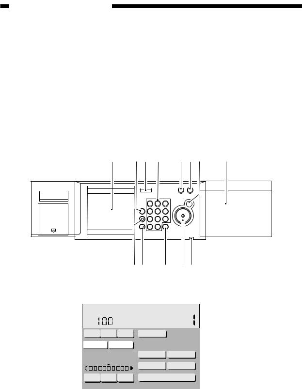
CHAPTER 1 GENERAL DESCRIPTION
IV. OPERATIONS
A. Control Panel
q Touch panel display w Guide key
e Reset key r Keypad
t Display Contrast key y Energy Saver key u Stop key
i Toner supply mouth o Pilot lamp
!0Copy Start key !1Clear key !2Interrupt key !3User Mode key !4Preferences key
q w e r t yu i
RESET |
|
|
1 |
|
STOP |
|
3 |
|
4 |
5 |
6 |
7 |
8 |
9 |
10 |
0 |
START |
!3!2 !1 !0o
Figure 1-401
Ready to copy.
|
|
|
|
% |
|
|
LTR |
|
|||||
|
REDUCE |
DIRECT ENLARGE |
PAPERSELECT |
||||||||||
|
FIT IMAGE |
ZOOM |
|
|
|
|
|
|
|
|
|||
|
|
|
|
|
|
|
|
|
!4 |
||||
|
|
|
|
|
|
|
|
||||||
|
|
|
|
|
|
|
|
|
|
|
|
|
|
|
|
|
|
|
|
|
|
|
|
|
|||
|
|
|
|
|
|
|
SORTER 2-SIDED |
||||||
|
|
|
|
|
|
||||||||
|
|
|
|
|
|
|
|
SPECIAL FEATURES |
|
|
|
|
|
|
LIGHT |
A |
DARK |
|
|
|
|
|
|
|
|||
|
|
|
|
||||||||||
Figure 1-402
1-12 |
COPYRIGHT © 1997 CANON INC. |
CANON NP6045 REV. 1 MAR. 1997 PRINTED IN JAPAN (IMPRIME AU JAPON) |
Loading...