


 Loading...
SERVICE MANUAL
REVISION 0
MAY 1997 |
FY8-13EX-000 |
COPYRIGHT © 1997 CANON INC. |
CANON NP6218 REV.0 MAY 1997 PRINTED IN JAPAN (IMPRIMÉ AU JAPON) |

IMPORTANT
THIS DOCUMENTATION IS PUBLISHED BY CANON INC., JAPAN, TO SERVE AS A SOURCE OF REFERENCE FOR WORK IN THE FIELD.
SPECIFICATIONS AND OTHER INFORMATION CONTAINED HEREIN MAY VARY SLIGHTLY FROM ACTUAL MACHINE VALUES OR THOSE FOUND IN ADVERTISING AND OTHER PRINTED MATTER.
ANY QUESTIONS REGARDING INFORMATION CONTAINED HEREIN SHOULD BE DIRECTED TO THE COPIER SERVICE DEPARTMENT OF THE SALES COMPANY.
THIS DOCUMENTATION IS INTENDED FOR ALL SALES AREAS, AND MAY CONTAIN INFORMATION NOT APPLICABLE TO CERTAIN AREAS.
COPYRIGHT © 1997 CANON INC.
Printed in Japan
Imprimé au Japon
Use of this manual should be strictly
supervised to avoid disclosure of
confidential information.
Prepared by
OFFICE IMAGING PRODUCTS TECHNICAL SUPPORT DEPT. 1
OFFICE IMAGING PRODUCTS TECHNICAL SUPPORT DIV.
CANON INC.
5-1, Hakusan 7-chome, Toride-shi, Ibaraki 302 Japan
COPYRIGHT © 1997 CANON INC. |
CANON NP6218 REV.0 MAY 1997 PRINTED IN JAPAN (IMPRIMÉ AU JAPON) |

INTRODUCTION
This Service Manual contains the bsic facts and figures about the plain paper copier NP6218, and is compiled to serve as a handy reference for servicing the machine in the field.
The NP6218 is designed to enable fully automated copying work and may be configured with the following accessories:
1.Cassette Feeding Module-B2*
2.Cassette Feeding Module-A2*
3.Control Card IV N
4.ADF-E1
5.Staple Sorter B2/D1
6.MS-B1
7.Remote Diagnostic Device II
This manual is limited to the descriptions of the NP6218, Cassette Feeding Module-
B2/Cassette Feeding Module-A2.
* May not be available in some areas but discussed in this manual.
This Service Manual covers the copier only, and consists of the following chapters:
Chapter 1 General Description introduces the copier's features and specifications, shows how to operate the copier, and explains how copies are made.
Chapter 2 Basic Operation provides outlines of the copier's various mechanical workings.
Chapter 3 Exposure System discusses the principles of operation used for the copier's lens drive unit and scanner drive unit. It also explains the timing at which these drive units are operated, and shows how they may be disassembled/assembled and adjusted.
Chapter 4 Image Formation System discusses the principles of how images are formed. It also explains the timing at which the various units involved in image formation are operated, and shows how they may be disassembled/assembled and adjusted.
Chapter 5 Pick-Up/Feeding System explains the principles used from when copy paper is picked up to when a copy is delivered in view of the functions of electrical and mechanical units and in relation to their timing of operation. It also shows how these units may be disassembled/assembled and adjusted.
Chapter 6 Fixing System explains the principles used to fuse toner images to transfer media in view of the functions of electrical and mechanical units and in relation to their timing of operation. It also shows how these units may be disassembled/assembled and adjusted.
Chapter 7 Externals/Auxiliary Mechanisms shows the copier's external parts, and explains the principles used for the copier's various control mechanisms in view of the functions of electrical and mechanical units and in relation to their timing of operation. It also shows how these units may be disassembled/assembled and adjusted.
Chapter 8 Installation introduces requirements for the site of installation, and shows how the copier may be installed using step-by-step instructions.
COPYRIGHT © 1997 CANON INC. |
CANON NP6218 REV.0 MAY 1997 PRINTED IN JAPAN (IMPRIMÉ AU JAPON) |
i |

Chapter 9 Maintenance and Servicing provides tables of periodically replaced parts and consumables/durables and scheduled servicing charts.
Chapter 10 Troubleshooting provides tables of maintenance/inspection, standards/adjustments, and problem identification (image fault/malfunction).
Appendix contains a general timing chart and general circuit diagrams.
In addition to the above chapters, this SERVICE MANUAL contains a set of appendixes consisting of a general timing chart and general circuit diagrams.
A separate document entitled SERVICE HANDBOOK is also available for troubleshooting problems in the copier.
The following rules apply throughout this volume:
1.Each chapter contains sections explaining the purpose of specific functions and the relationship between electrical and mechanical systems with reference to the timing of operation.
In the diagrams, 


 represents the path of mechanical drive—where a signal name accompanies the symbol
  , the arrow indicates the direction of the electric signal.
The expression “turn on the power” means flipping on the power switch, closing the front door, and closing the delivery unit door, which will result in supplying the machine with power.
2.In the digital circuits, ‘1’ is used to indicate that the voltage level of a given signal is
“High,” while ‘0’ is used to indicate “Low.” (The voltage value, however, differs from circuit to circuit.)
In practically all cases, the internal mechanisms of a microprocessor cannot be checked in the field. Therefore, the operations of the microprocessors used in the machines are not discussed: they are explained in terms of from sensors to the input of the DC controller PCB and from the output of the DC controller PCB to the loads.
The contents of this manual may be updated from time to time to reflect improvements rendered to the copier; a Service Information bulletin will be issued as necessary to cover major changes.
All service persons are expected to be thoroughly familiar with the information contained in this manual, SERVICE HANDBOOK, and Service Information bulletins, for quick response to the user’s needs.
ii |
COPYRIGHT © 1997 CANON INC. |
CANON NP6218 REV.0 MAY 1997 PRINTED IN JAPAN (IMPRIMÉ AU JAPON) |
System Configuration
The NP6218 may be configured with the following systems options:
ADF-E1
Sends originals one by one from a stack set on its tray
Control Card IV N
Allows the user to control copy volume.
Stapler Sorter B2/D1, MS-B1
Automatically sorts or (page collation) or groups up to 10 sets of copies; with the sorting function,
the sorted copies may automatically be stapled. (Not applicable to MS-B1.)
Cassette Feeding Module-B2
Adds an additional cassette.
Cassette Feeding Module-A2
Adds additional two cassettes.
|
|
|
|
iii |
COPYRIGHT © 1997 CANON INC. |
CANON NP6218 REV.0 MAY 1997 PRINTED IN JAPAN (IMPRIMÉ AU JAPON) |
|||

1. GENERAL DESCRIPTION
iv
COPYRIGHT © 1997 CANON INC. |
CANON NP6218 REV.0 MAR. 1997 PRINTED IN JAPAN (IMPRIMÉ AU JAPON) |
CONTENTS
CHAPTER 1 GENERAL DESCRIPTION
I. |
FEATURES ......................................... |
|
1-1 |
|
II. |
SPECIFICATIONS .............................. |
1-2 |
||
|
A. Copier ............................................ |
|
1-2 |
|
|
1. |
Type .......................................... |
|
1-2 |
|
2. |
System ..................................... |
|
1-2 |
|
3. |
Features ................................... |
|
1-3 |
|
4. |
Others....................................... |
|
1-4 |
|
B. Cassette Feeding Module-B2/ |
|
||
|
Cassette Feeding Module-A2 ........ |
1-5 |
||
III. |
NAMES OF PARTS ............................ |
1-6 |
||
|
A. Exterior View ................................. |
|
1-6 |
|
|
B. Cross Section ................................ |
|
1-7 |
|
|
1. |
Body ......................................... |
|
1-7 |
|
2. |
Cassette Feeding Module-A2... |
1-8 |
|
IV. |
OPERATION ....................................... |
|
1-9 |
|
|
A. Control Panel................................. |
|
1-9 |
|
|
B. Operation Mode............................. |
1-10 |
||
|
C. Making Two-Sided/Overlay |
|
||
|
Copies (manual) ............................ |
1-11 |
||
|
D. User Mode ..................................... |
|
1-12 |
|
|
1. |
Outline ...................................... |
|
1-12 |
|
2. |
Common Operations ................ |
1-13 |
|
|
3. |
Changing the Auto Clear |
|
|
|
|
Time ( |
) .............................. |
1-13 |
4. |
Changing the Auto Power-Off |
|
||
|
Time ( |
) .............................. |
|
1-13 |
5. |
Zoom Fine-Adjustment ( |
).. |
1-14 |
|
6.Turning On and Off the Auto Cassette Change Mechanism
( |
) ....................................... |
1-15 |
7.Turning On/Off the Auto Sort/ Non-Sort (with ADF and sorter
installed—option) ( |
) .......... |
1-16 |
8. Cleaning the Feeder (with ADF |
||
installed—option) ( |
) .......... |
1-16 |
9.Selecting the Density Adjustment Method for
|
Standard Mode ( |
) ............. |
|
1-17 |
|
10.Initializing User Mode ( |
).... |
1-17 |
|
|
11.Quick Guide to User Mode....... |
|
1-18 |
|
|
E. Handling the Toner Bottle .............. |
|
1-19 |
|
V. |
WARNINGS AND ACTIONS .............. |
|
1-19 |
|
VI. |
ROUTINE MAINTENANCE BY THE |
|
||
|
USER.................................................. |
|
|
1-19 |
VII. IMAGE FORMATION .......................... |
|
|
1-20 |
|
|
A. Outline ........................................... |
|
|
1-20 |
CHAPTER 2 BASIC OPERATION
I. BASIC CONSTRUCTION ................... |
2-1 |
|
A. Functional Construction................. |
2-1 |
|
B. Outline of the Electrical Circuitry... |
2-2 |
|
C. Basic Sequence of Operations |
|
|
(2 copies continuous, AE) ............. |
2-3 |
|
D. Main Motor Control Circuit............. |
2-4 |
|
1. |
Outline ...................................... |
2-4 |
2. |
Mechanism ............................... |
2-4 |
E. Inputs to the DC Controller PCB ... |
2-5 |
|
1. |
Inputs to the DC Controller |
|
|
PCB (1/3).................................. |
2-5 |
2. |
Inputs to the DC Controller |
|
|
PCB (2/3).................................. |
2-6 |
3. |
Inputs to the DC Controller |
|
|
PCB (3/3).................................. |
2-7 |
F. Outputs from the DC Controller |
|
|
PCB ............................................... |
2-8 |
|
1. |
Outputs from the DC |
|
|
Controller PCB (1/3) ................. |
2-8 |
2. |
Outputs from the DC |
|
|
Controller PCB (2/3) ................. |
2-9 |
3. |
Outputs from the DC |
|
|
Controller PCB (3/3) ................. |
2-10 |
G. Inputs to and Outputs from the |
|
|
1-Cassette Unit Driver PCB........... |
2-11 |
|
1. |
Inputs to and Outputs from |
|
|
the 1-Cassette Unit Driver |
|
|
PCB (1/1).................................. |
2-11 |
H. Inputs to and Outputs from the |
|
|
2-Cassette Unit Driver PCB........... |
2-12 |
|
1. |
Inputs to and Outputs from |
|
|
the 2-Cassette Unit Driver |
|
|
PCB (1/2).................................. |
2-12 |
2.Inputs to and Outputs from the 2-Cassette Unit Driver
PCB (2/2).................................. |
2-13 |
COPYRIGHT © 1997 CANON INC. |
CANON NP6218 REV.0 MAY 1997 PRINTED IN JAPAN (IMPRIMÉ AU JAPON) |
v |

CHAPTER 3 EXPOSURE SYSTEM
I. |
BASIC OPERATION ........................... |
3-1 |
IV. DISASSEMBLY AND ASSEMBLY ...... |
3-9 |
||
|
A. Varying the Reproduction Ratio .... |
3-1 |
A. Scanner Drive Assembly ............... |
3-9 |
||
II. |
LENS DRIVE SYSTEM ...................... |
3-1 |
1. |
Detaching the Scanner Drive |
|
|
|
A. Outline ........................................... |
3-1 |
|
Motor ........................................ |
3-9 |
|
|
B. Lens Motor Drive Circuit................ |
3-3 |
2. |
Detaching the Scanner Cable .. |
3-10 |
|
|
1. |
Keeping the Lens Motor |
|
3. |
Assembling the Mirror |
|
|
|
Stationary ................................. |
3-3 |
|
Position Tool ............................. |
3-12 |
|
2. |
Driving the Lens Motor ............. |
3-3 |
4. |
Routing the Scanner Cable ...... |
3-13 |
|
C. Basic Sequence of Operations |
|
5. |
Adjusting the Position of the |
|
|
|
(lens drive system; non-Direct) ...... |
3-4 |
|
Mirrors (optical length of No. |
|
|
III. |
SCANNING DRIVE SYSTEM............. |
3-5 |
|
1, 2, and 3 mirrors)................... |
3-16 |
|
|
A. Driving the Scanner....................... |
3-5 |
6. |
Cleaning the Scanner No. 6 |
|
|
|
1. |
Outline ...................................... |
3-5 |
|
Mirror ........................................ |
3-17 |
|
2. |
Relationship between the |
|
B. Lens Drive Assembly..................... |
3-18 |
|
|
|
Scanner Sensor and Signals.... |
3-6 |
1. |
Detaching the Lens Drive |
|
|
3. |
Basic Sequence of |
|
|
Motor ........................................ |
3-18 |
|
|
Operations (scanner)................ |
3-6 |
2. |
Routing the Lens Cable............ |
3-20 |
|
4. |
Driving the Scanner Motor ....... |
3-7 |
3. |
Adjusting the Position of the |
|
|
5. |
Scanner Operations in Page |
|
|
Change Solenoid...................... |
3-21 |
|
|
Separation Mode (non-AE, |
|
|
|
|
|
|
page separation, A4, 2 copies).. |
3-8 |
|
|
|
CHAPTER 4 IMAGE FORMATION SYSTEM
I. |
PROCESSES ..................................... |
4-1 |
3. |
Controlling the Primary |
|
|
|
A. Outline ........................................... |
4-1 |
|
Charging Roller Bias to a |
|
|
|
B. Basic Sequence of Operations |
|
|
Constant Voltage ...................... |
4-11 |
|
|
(image formation system).............. |
4-3 |
4. |
Switching the Primary Charging |
||
|
C. Controlling the Scanning Lamp ..... |
4-4 |
|
Roller Bias Application Voltage |
|
|
|
1. |
Outline ...................................... |
4-4 |
|
Level ......................................... |
4-11 |
|
2. |
Turning On and Off the |
|
5. |
Application Voltage Level |
|
|
|
Scanning Lamp ........................ |
4-5 |
|
(APVC) for the Primary |
|
|
3. |
Pre-Heating Control |
|
|
Charging Roller and Scanning |
|
|
|
(scanning lamp)........................ |
4-5 |
|
Lamp On Voltage Level |
|
|
4. |
Sequence of Operations |
|
|
Automatic Correction ................ |
4-12 |
|
|
(scanning lamp pre-heating |
|
E. Controlling the Transfer Roller Bias... |
4-13 |
|
|
|
control; AE, A4, continuous, |
|
1. |
Outline ...................................... |
4-13 |
|
|
2 copies)................................... |
4-5 |
2. |
Turning On and Off the |
|
|
5. |
Controlling the Intensity of the |
|
|
Transfer Roller Bias .................. |
4-15 |
|
|
Scanning Lamp (FL1)............... |
4-7 |
3. |
Controlling the Transfer Bias |
|
|
6. |
Controlling the Fluorescent |
|
|
to a Constant Voltage ............... |
4-15 |
|
|
Lamp Heater............................. |
4-8 |
4. |
Controlling the Transfer Bias |
|
|
7. |
Fluorescent Lamp Automatic ... |
4-9 |
|
Voltage Level Correction |
|
|
8. |
Fluorescent Lamp Protection |
|
|
(ATVC control) .......................... |
4-15 |
|
|
Mechanism ............................... |
4-9 |
5. |
Current Limiter Circuit |
|
|
D. Controlling the Primary Charging |
|
|
(transfer bias) ........................... |
4-15 |
|
|
Roller Bias ..................................... |
4-10 |
6. |
Current Limiter Circuit |
|
|
|
1. |
Outline ...................................... |
4-10 |
|
(cleaning bias) .......................... |
4-15 |
|
2. |
Turning On and Off the Primary |
F. Controlling the Static Eliminator |
|
||
|
|
Charging Roller Bias ................ |
4-11 |
Bias................................................ |
4-16 |
|
vi |
COPYRIGHT © 1997 CANON INC. |
CANON NP6218 REV.0 MAY 1997 PRINTED IN JAPAN (IMPRIMÉ AU JAPON) |

1. |
Outline ...................................... |
4-16 |
III. DISASSEMBLY AND ASSEMBLY ...... |
4-30 |
|
2. |
Switching the Static Eliminator |
|
A. Illumination Assembly.................... |
4-30 |
|
|
Bias Voltage Level .................... |
4-17 |
1. |
Detaching the Scanning |
|
3. |
Ensuring Proper Separation of |
|
|
Lamp/Fluorescent Lamp |
|
|
Thin Paper ................................ |
4-17 |
|
Heater....................................... |
4-30 |
G. Controlling Blank Exposure ........... |
4-18 |
2. |
Points to Note When Attaching |
|
|
1. |
Outline ...................................... |
4-18 |
|
the Fluorescent Lamp |
|
2. |
Blanking (Whiting) of Non- |
|
|
Heater/Scanning Lamp............. |
4-32 |
|
Image Areas for Reduction....... |
4-19 |
3. |
Detaching the Blank Exposure |
|
3. |
Blanking (Whiting) Out the |
|
|
Assembly .................................. |
4-34 |
|
Leading/Trailing Edges and |
|
4. |
Detaching the Blank Exposure |
|
|
between Copies........................ |
4-19 |
|
Lamp ........................................ |
4-35 |
H. Controlling the Primary Corona |
|
5. |
Detaching the Blank Shutter |
|
|
Roller Cleaning Mechanism .......... |
4-20 |
|
Solenoid ................................... |
4-36 |
|
1. |
Outline ...................................... |
4-20 |
6. |
Positioning the Blank Shutter |
|
2. |
Primary Charging Roller |
|
|
Solenoid ................................... |
4-37 |
|
Cleaning Operation .................. |
4-20 |
7. |
Routing the Blanking Cable...... |
4-38 |
I. Releasing the Transfer Roller ........ |
4-21 |
8. |
Positioning the Left/Right |
|
|
1. |
Outline ...................................... |
4-21 |
|
Margin ...................................... |
4-38 |
II. DEVELOPING ASSEMBLY AND |
|
B. Drum Unit ...................................... |
4-39 |
||
CLEANING ASSEMBLY ..................... |
4-22 |
1. Detaching the Drum Unit.......... |
4-39 |
||
A. Outline ........................................... |
4-22 |
2. |
Cleaning ................................... |
4-40 |
|
B. Controlling the Toner Level |
|
C. Primary Corona Assembly............. |
4-41 |
||
Detection ....................................... |
4-23 |
1. |
Detaching the Primary Corona |
|
|
C. Controlling the Development |
|
|
Assembly .................................. |
4-41 |
|
Bias................................................ |
4-25 |
2. |
Cleaning the Cleaning Pad and |
||
1. |
Outline ...................................... |
4-25 |
|
the Primary Corona Roller ....... |
4-42 |
2. |
Turning On and Off the DC |
|
3. |
Positioning the Solenoid for the |
|
|
Component of the Developing |
|
|
Primary Charging Roller........... |
4-43 |
|
Bias and Controlling the |
|
D. Transfer Charging Assembly ......... |
4-44 |
|
|
Voltage to a Constant Level ..... |
4-25 |
1. |
Detaching the Transfer Roller ... |
4-44 |
3. |
Turning On and Off the AC |
|
2. |
Attaching the Drum Heater....... |
4-44 |
|
Component of the |
|
E. Developing System........................ |
4-47 |
|
|
Development Bias .................... |
4-26 |
1. |
Removing the Developing |
|
4. |
Controlling the Voltage Level |
|
|
Assembly .................................. |
4-47 |
|
of the DC Component of the |
|
2. |
Removing the Blade |
|
|
Development Bias .................... |
4-26 |
|
Assembly .................................. |
4-47 |
D. Automatic Control of Copy |
|
3. |
Removing the Developing |
|
|
Density........................................... |
4-27 |
|
Cylinder Side Seal.................... |
4-48 |
|
1. |
Outline ...................................... |
4-27 |
4. |
Installing the Side Seal and |
|
2. |
Control Method......................... |
4-27 |
|
the Blade Assembly.................. |
4-51 |
3. |
AE Adjustment.......................... |
4-29 |
|
|
|
CHAPTER 5 PICK-UP/FEEDING SYSTEM
I. |
PICK-UP/FEEDING SYSTEM ............ |
5-1 |
|
A. Outline ........................................... |
5-1 |
II. |
PICK-UP OPERATION (COPIER) ...... |
5-3 |
|
A. Outline ........................................... |
5-3 |
|
B. Sequence of Operations (pick-up/ |
|
|
feeding assembly; A4, 2 copies).... |
5-4 |
III.PICK-UP FROM THE CASSETTE
FEEDING MODULE-A2...................... |
5-5 |
A. Pick-Up Operation ......................... |
5-5 |
B. Sequence of Operations |
|
(cassette 2; A4, 2 copies) .............. |
5-6 |
IV. MULTIFEEDER................................... |
5-7 |
A. Outline ........................................... |
5-7 |
B. Identifying the Size of Paper on |
|
the Multifeeder............................... |
5-8 |
C. Sequence of Operations |
|
(multifeeder; A4, 2 copies)............. |
5-9 |
V.IDENTIFYING THE CASSETTE
SIZE.................................................... |
5-10 |
VI. IDENTIFYING JAMS .......................... |
5-12 |
A. Pre-Registration Delay Jam........... |
5-12 |
B. Pre-Registration Timing Jam ......... |
5-13 |
COPYRIGHT © 1997 CANON INC. |
CANON NP6218 REV.0 MAY 1997 PRINTED IN JAPAN (IMPRIMÉ AU JAPON) |
vii |

C. Pre-Registration Stationary Jam ... |
5-13 |
|
D. Separation Delay Jam ................... |
5-14 |
|
E. Separation Stationary Jam ............ |
5-14 |
|
F. Delivery Delay Jam........................ |
5-15 |
|
G. Delivery Stationary Jam ................ |
5-15 |
|
VII. DISASSEMBLY AND ASSEMBLY ...... |
5-16 |
|
A. Pick-Up Assembly ......................... |
5-16 |
|
1. |
Detaching the Pick-Up Roller |
|
|
Unit ........................................... |
5-16 |
2. |
Detaching the Pick-Up Roller ... |
5-19 |
3. |
Points to Note When Attaching |
|
|
the Pick-Up Roller .................... |
5-20 |
4.Detaching the Pick-Up Clutch...5-20
5.Detaching the Separation Pad ..5-21
6.Adjusting the Left/Right
|
Registration .............................. |
5-22 |
B. Multifeeder Assembly .................... |
5-23 |
|
1. |
Detaching the Multifeeder |
|
|
Assembly .................................. |
5-23 |
2. |
Detaching the Multifeeder |
|
|
Pick-Up Roller Unit ................... |
5-24 |
3. |
Detaching the Multifeeder |
|
|
Pick-Up Roller .......................... |
5-25 |
4. |
Points to Keep Note When |
|
|
Attaching the Multifeeder |
|
|
Pick-Up Roller .......................... |
5-26 |
5. |
Detaching the Separation Pad .. |
5-26 |
6. |
Detaching the Multifeeder |
|
|
Drive Unit.................................. |
5-27 |
7. |
Detaching the Multifeeder |
|
|
Clutch ....................................... |
5-28 |
8.Positioning the Multifeeder Assembly (paper guide plate
|
cam) ......................................... |
5-29 |
9. |
Adjusting the Left/Right |
|
|
Registration .............................. |
5-30 |
10.Points to Note When Attaching |
|
|
|
the Multifeeder Assembly Rack |
|
|
Plate ......................................... |
5-30 |
C. Registration Roller Assembly ........ |
5-31 |
|
1. |
Detaching the Registration |
|
|
Clutch ....................................... |
5-31 |
2. |
Detaching the Upper |
|
|
Registration Roller.................... |
5-31 |
3. |
Detaching the Lower |
|
|
Registration Roller.................... |
5-33 |
D. Feeding Assembly ......................... |
5-34 |
|
1. |
Detaching the Feeding Belt ...... |
5-34 |
E. Cassette Unit ................................. |
5-36 |
|
1. |
Detaching the Copier from |
|
|
the Cassette Unit...................... |
5-36 |
2. |
Detaching/Attaching the |
|
|
Pick-Up Roller .......................... |
5-36 |
3. |
Detaching the Pick-Up Clutch .. |
5-36 |
CHAPTER 6 FIXING SYSTEM
I. |
BASIC OPERATIONS......................... |
6-1 |
|
|
A. Outline ........................................... |
6-1 |
|
|
B. Controlling the Fixing Heater |
|
|
|
Temperature .................................. |
6-3 |
|
|
C. Controlling the Supply Power for |
|
|
|
the Fixing Heater ........................... |
6-5 |
|
|
D. Detecting Overheating at the End |
|
|
|
of the Fixing Heater ....................... |
6-6 |
|
|
E. Protection Mechanism ................... |
6-6 |
|
|
1. |
Thermistor (TH1, TH2) ............. |
6-6 |
|
2. |
Thermal Fuse (FU1)................. |
6-6 |
|
3. |
Heater ON Detection Circuit |
|
|
|
(230V model only) .................... |
6-6 |
|
F. Correcting Displacement of the |
|
|
|
Fixing Film ..................................... |
6-7 |
|
|
1. |
Outline ...................................... |
6-7 |
|
2. |
Controlling the Fixing Film |
|
|
|
Motor ........................................ |
6-10 |
II. |
DISASSEMBLY AND ASSEMBLY ...... |
6-11 |
|
|
A. Fixing Assembly ............................ |
6-11 |
|
|
1. |
Construction1 ........................... |
6-11 |
|
2. |
Detaching the Upper Fixing |
|
|
|
Unit ........................................... |
6-12 |
3.Detaching the Fixing Film, Tension Roller, Drive Roller, Fixing Cleaning Brush, and
|
Fixing Heater Unit .................... |
6-13 |
4. |
Points to Note When Attaching |
|
|
the Fixing Film ......................... |
6-20 |
5. |
Points to Note When Attaching |
|
|
the Heater Connector ............... |
6-20 |
6. |
Points to Note When Replacing |
|
|
the Fixing Upper Unit ............... |
6-21 |
7. |
Adjusting the Fixing Film Drive |
|
|
Roller Pressure......................... |
6-21 |
8. |
Detaching the Lower Fixing |
|
|
Unit ........................................... |
6-23 |
9.Detaching the Separation Claw/Lower Fixing Claw and
Fixing Cleaning Roller .............. |
6-24 |
10.Adjusting the Lower Fixing |
|
Roller Nip.................................. |
6-25 |
B. Delivery Assembly ......................... |
6-27 |
viii |
COPYRIGHT © 1997 CANON INC. |
CANON NP6218 REV.0 MAY 1997 PRINTED IN JAPAN (IMPRIMÉ AU JAPON) |
CHAPTER 7 EXTERNALS/AUXILIARY MECHANISMS
I. POWER SUPPLY ............................... |
7-1 |
A. Outline ........................................... |
7-1 |
B. Power Supply Circuit Assembly..... |
7-2 |
C. Detecting Errors in the Power |
|
Supply PCB ................................... |
7-4 |
1.Communication Error between DC Controller PCB and Composite Power Supply PCB ..7-4
2.Error in the High-Voltage
Output Data .............................. |
7-4 |
3.Low-Voltage Output Data Error..7-4
4.Overcurrent in the Low-voltage
Power Supply ........................... |
7-4 |
D. Protection Mechanisms for the |
|
Power Supply Circuit ..................... |
7-5 |
II. DISASSEMBLY AND ASSEMBLY ...... |
7-6 |
A. External Covers ............................. |
7-6 |
B. Control Panel................................. |
7-9 |
1. Detaching the Control Panel .... |
7-9 |
C. Fans............................................... |
7-10 |
1. Detaching the Exhaust Fan ...... |
7-10 |
D.Main Motor/Main Drive Assembly..7-11
1.Detaching the Main Motor Unit..7-11
2.Detaching the Main Drive
Assembly .................................. |
7-11 |
3. |
Routing the Drive Belt .............. |
7-13 |
E. Cassette unit ................................. |
7-14 |
|
1. |
Detaching the Pick-Up Drive |
|
|
Unit ........................................... |
7-14 |
2.Detaching the Cassette Motor..7-15
3.Detaching the Cassette Driver
|
PCB .......................................... |
7-16 |
F. DC Controller PCB ........................ |
7-17 |
|
1. |
Detaching the DC Controller |
|
|
PCB .......................................... |
7-17 |
2. |
Points to Note When |
|
|
Replacing the DC Controller |
|
|
PCB .......................................... |
7-17 |
G. Composite Power Supply PCB...... |
7-18 |
|
1. |
Detaching the Composite |
|
|
Power Supply PCB ................... |
7-18 |
2.Points to Note When Handling the Composite Power Supply
|
PCB .......................................... |
7-20 |
H. AE Sensor PCB............................. |
7-21 |
|
1. |
Points to Note When |
|
|
Replacing the AE Sensor ......... |
7-21 |
I. Intensity Sensor PCB .................... |
7-21 |
|
1. |
Points to Note When Replacing |
|
|
the Intensity Sensor ................. |
7-21 |
CHAPTER 8 INSTALLATION
I. SELECTING THE SITE ...................... |
8-1 |
II.UNPACKING AND INSTALLING
|
THE COPIER...................................... |
8-2 |
|
A. Unpacking and Removing Fixings .. |
8-2 |
|
B. Turning On the Copier ................... |
8-5 |
|
C. Checking the Images and |
|
|
Operations ..................................... |
8-8 |
|
D. Attaching the Drum Unit ................ |
8-9 |
|
E. Changing the Cassette Size.......... |
8-10 |
III. |
RELOCATING THE COPIER.............. |
8-13 |
IV. |
REPLACING THE DRUM UNIT.......... |
8-14 |
V.INSTALLING THE CONTROL CARD
|
IV N..................................................... |
8-17 |
VI. |
CASSETTE HEATER KIT 5 |
|
|
INSTALLATION PROCEDURE ........... |
8-19 |
|
A. Unpacking...................................... |
8-19 |
|
B. Installation (to a Cassette |
|
|
Feeding Module-A2/B2)................. |
8-20 |
VII. INSTALLING THE REMOTE |
|
|
|
DIAGNOSTIC DEVICE II.................... |
8-26 |
|
A. Unpacking...................................... |
8-26 |
|
B. Installation to the Copier ............... |
8-27 |
CHAPTER 9 MAINTENANCE AND SERVICING
I. |
PERIODICALLY REPLACED |
|
|
B. Cassette Feeding Module-B2/ |
|
|
PARTS ................................................ |
9-1 |
|
Cassette Feeding Module-A2 ........ |
9-3 |
|
A. Periodically Replaced Parts........... |
9-1 |
III. |
PERIODICAL SERVICING ................. |
9-4 |
II. |
DURABLES ........................................ |
9-2 |
IV. |
SERVICING CHART........................... |
9-5 |
|
A. Copier ............................................ |
9-2 |
V. |
NOTES ON DRUM KIT ...................... |
9-6 |
COPYRIGHT © 1997 CANON INC. |
CANON NP6218 REV.0 MAY 1997 PRINTED IN JAPAN (IMPRIMÉ AU JAPON) |
ix |

CHAPTER 10 TROUBLESHOOTING
I.MAINTENANCE AND INSPECTION..10-3 A. Image Adjustment Basic
Procedure.................................... |
10-3 |
B. Periodical Servicing..................... |
10-4 |
II.STANDARDS AND ADJUSTMENTS..10-5
A. Image Adjustment ....................... |
10-5 |
1.Adjusting the Image Leading Edge Margin ([3], No.305;
registration ON timing) ........... |
10-5 |
2.Adjusting the Leading Edge Non-Image Width ([3], No. 306; blank shutter ON
timing)..................................... |
10-6 |
3.Adjusting the Image Trailling Edge Non-Image Width ([3], No.309; blank shutter
|
timing)..................................... |
10-7 |
4. |
Adjusting the Left/Right |
|
|
Registration ............................ |
10-8 |
5. |
Adjusting the Left/Right Margin |
|
|
(No.311; left/right margin)....... |
10-9 |
6. |
Adjusting the Scanning Lamp |
|
|
Intensity .................................. |
10-10 |
7. |
AE Adjustment ....................... |
10-11 |
B. Exposure System ........................ |
10-15 |
|
1. |
Routing the Scanner Drive |
|
|
Cable ...................................... |
10-15 |
2.Adjusting the Mirror Position optical distance between No.1 mirror and No.2/No.3 mirror) ..10-16
3.Adjusting the Scanner Cable
Tension ................................... |
10-17 |
4. Assembling the Mirror |
|
Positioning Tool ...................... |
10-17 |
5.Points to Note When Attaching the Fluorescent Lamp Heater/
|
Scanning Lamp ...................... |
10-18 |
6. |
Positioning the Change |
|
|
Solenoid ................................. |
10-20 |
C. Image Formation System ............ |
10-21 |
|
1. |
Positioning the Blank Shutter |
|
|
Solenoid ................................. |
10-21 |
2. |
Routing the Blank Shutter |
|
|
Cable ...................................... |
10-22 |
3. |
Positioning the Solenoid for the |
|
|
Primary Charging Roller......... |
10-22 |
4. |
After Replacing the Drum |
|
|
Unit ......................................... |
10-23 |
5. |
Attaching the Drum Heater .... |
10-23 |
D. Pick-Up/Feeding System ............. |
10-25 |
|
1. |
Orientation of the Pick-Up |
|
|
Roller ...................................... |
10-25 |
2. |
Orientation of the Multifeeder |
|
|
Pick-up Roller ......................... |
10-25 |
3. |
Positioning the paper Guide |
|
|
Plate Cam (multifeeder) ......... |
10-26 |
E. Fixing System.............................. |
10-27 |
|
1. |
Points to Note when Attaching |
|
|
the Fixing Film........................ |
10-27 |
2. |
Points to Note when Attaching |
|
|
the Heater Connector............. |
10-27 |
3. |
Adjusting the Fixing Film Drive |
|
|
Roller Pressure ...................... |
10-28 |
4. |
Points to Note after Replacing |
|
|
the Fixing Upper Unit ............. |
10-29 |
5. |
Adjusting the Nip .................... |
10-30 |
6. |
Routing the Drive Belt ............ |
10-31 |
7. |
Storing the Fixing Heater |
|
|
Registance ............................. |
10-31 |
8. |
Setting the Fixing Heater |
|
|
Temperature Control Value..... |
10-32 |
F. Electrical...................................... |
10-35 |
|
1. |
After Replacing the PCB ........ |
10-35 |
2. |
Clearing the Back-Up RAM.... |
10-35 |
3. |
Checking the |
|
|
Photointerrupters.................... |
10-36 |
4. |
Adjusting the Multifeeder |
|
|
Paper width Sensor ................ |
10-43 |
5. |
Setting the Paper Size for the |
|
|
Universal Cassette ................. |
10-44 |
III.TROUBLESHOOTING IMAGE
FAULTS............................................. |
10-45 |
|
A. Initial Checks ............................... |
10-45 |
|
1. |
Site Environment .................... |
10-45 |
2. |
Checking the Originals ........... |
10-45 |
3.Checking the Copyboard Cover and the Copyboard
|
Glass ...................................... |
10-45 |
4. |
Checking the Paper................ |
10-45 |
5. |
Others..................................... |
10-46 |
B. Samples of Image Faults............. |
10-48 |
|
C. Troubleshooting Faulty Images.... |
10-49 |
|
1. |
The copy is too light |
|
|
(half-tone only). ...................... |
10-49 |
2. |
The copy is too light |
|
|
(black solid also)..................... |
10-50 |
3. |
The copy is too light |
|
|
(overall, extremely). ................ |
10-50 |
4. |
The copy has uneven density |
|
|
(front too dark)........................ |
10-52 |
5. |
The copy has uneven density |
|
|
(front too light). ....................... |
10-52 |
6. |
The copy is foggy (overall). .... |
10-53 |
7. |
The copy is foggy (vertical). ... |
10-54 |
8. |
The copy has black lines |
|
|
(vertical; thick fuzzy lines). ..... |
10-54 |
9. |
The copy has black lines |
|
|
(vertical, fine).......................... |
10-54 |
x |
COPYRIGHT © 1997 CANON INC. |
CANON NP6218 REV.0 MAY 1997 PRINTED IN JAPAN (IMPRIMÉ AU JAPON) |
10.The copy has white spot |
|
|
|
(vertical).................................. |
10-55 |
11.The copy has white lines |
|
|
|
(vertical).................................. |
10-55 |
12.The copy has white spots |
|
|
|
(horizontal). ............................ |
10-56 |
13.The back of the copy is |
|
|
|
soiled. ..................................... |
10-57 |
14.The copy has a fixing fault. .... |
10-58 |
|
15.The leading edge of the copy |
|
|
|
is displaced. ........................... |
10-58 |
16.The leading edge of the copy |
|
|
|
is displaced. ........................... |
10-58 |
17.The leading edge of the copy |
|
|
|
is displaced. ........................... |
10-58 |
18.The copy has a blurred |
|
|
|
image...................................... |
10-59 |
19.The copy is foggy |
|
|
|
(horizontal). ............................ |
10-60 |
20.The copy has poor |
|
|
|
sharpness............................... |
10-61 |
21.The copy is blank. .................. |
10-62 |
|
22.The copy is solid black. .......... |
10-62 |
|
IV. TROUBLESHOOTING |
|
|
MALFUNCTIONS ............................. |
10-63 |
|
A. Troubleshooting Malfunctions...... |
10-63 |
|
1. |
E000 ....................................... |
10-63 |
2. |
E001 ....................................... |
10-64 |
3. |
E002, E003 ............................ |
10-64 |
4. |
E004 ....................................... |
10-65 |
5. |
E007 ....................................... |
10-65 |
6. |
E010 ....................................... |
10-66 |
7. |
E030 ....................................... |
10-66 |
8. |
E064 ....................................... |
10-67 |
9. E202 (keys on control panel |
|
|
|
invalidated) ............................. |
10-67 |
10.E210 ....................................... |
10-68 |
|
11.E220 ....................................... |
10-68 |
|
12.E240 ....................................... |
10-68 |
|
13.E261 ....................................... |
10-69 |
|
14.E710, E711, E712, E717 ....... |
10-69 |
|
15.E803 ....................................... |
10-69 |
|
16.AC power supply is absent..... |
10-70 |
|
17.DC power supply is absent. ... |
10-71 |
|
18.The blank shutter fails to |
|
|
|
move....................................... |
10-72 |
19.The photosensitive drum fails |
|
|
|
to rotate. ................................. |
10-72 |
20.The pick-up operation fails |
|
|
|
(from cassette). ...................... |
10-73 |
21.The pick-up operation from |
|
|
|
the multifeeder fails. ............... |
10-73 |
22.The scanner fails to move |
|
|
|
forward/in reverse................... |
10-74 |
23.The registration roller fails to |
|
|
|
rotate. ..................................... |
10-74 |
24.The scanning lamp fails to |
|
|
|
turn on. ................................... |
10-75 |
25.The lens fails to move. ........... |
10-75 |
26.The fixing heater fails to |
|
operate. .................................. |
10-76 |
27.The pre-exposure lamp fails |
|
to turn on................................ |
10-76 |
28.The add paper indicator fails |
|
to turn off. ............................... |
10-76 |
29 The jam message fails to turn |
|
off. .......................................... |
10-77 |
V.TROUBLESHOOTING FEEDING
PROBLEMS..................................... |
10-78 |
|
A. Jams (copy paper)....................... |
10-78 |
|
1. |
Pick-Up Assembly .................. |
10-79 |
2. |
Separation/Feeding |
|
|
Assembly................................ |
10-80 |
3. |
Fixing/Delivery Assembly ....... |
10-80 |
B. Feeding Faults............................. |
10-81 |
|
1. |
Double feeding ....................... |
10-81 |
2. |
Wrinkling................................. |
10-81 |
VI. ARRANGEMENT AND FUNCTIONS |
||
OF THE ELECTRICAL PARTS......... |
10-82 |
|
A. Sensors ....................................... |
10-82 |
|
B. Clutches, Solenoids, and |
|
|
Switches ...................................... |
10-84 |
|
C. Motors, Heaters, and Lamps....... |
10-86 |
|
D. PCBs ........................................... |
10-88 |
|
E. Cassette Feeding Module-A2...... |
10-90 |
|
F. Variable Registors (VR) and |
|
|
check Pins by PCB...................... |
10-92 |
|
1. |
DC controller PCB.................. |
10-92 |
2. |
Composite power supply |
|
|
PCB ........................................ |
10-93 |
VII. SERVICE MODE .............................. |
10-94 |
|
A. Outline ......................................... |
10-94 |
|
B. Using Service Mode .................... |
10-94 |
|
1. |
Activating Service Mode......... |
10-94 |
2. |
Selecting a Service Mode ...... |
10-95 |
3. |
Selecting Items....................... |
10-95 |
4. |
Using Adjustment Mode [3] |
|
|
and Specification Mode [5]..... |
10-95 |
5. |
Using Operation/Inspection |
|
|
Mode [4] ................................. |
10-95 |
6. |
Clearing Stored Error ............. |
10-95 |
7. |
Recording on the Service |
|
|
Mode Label ............................ |
10-96 |
C. Control Display Mode [1]............. |
10-97 |
|
D. I/O Mode [2] ................................ |
10-99 |
|
E. Adjustment Mode [3] ................... |
10-102 |
|
F. Operation/Inspection Mode [4] .... |
10-105 |
|
G. Specification Settings Mode [5]... |
10-107 |
|
H. Counter Mode [6] ........................ |
10-108 |
|
VIII. SELF DIAGNOSIS............................ |
10-109 |
|
A. Copier.......................................... |
10-109 |
|
B. Self Diagnosis (ADF)................... |
10-113 |
|
C. Self Diagnosis (Sorter) ................ |
10-114 |
|
COPYRIGHT © 1997 CANON INC. |
CANON NP6218 REV.0 MAY 1997 PRINTED IN JAPAN (IMPRIMÉ AU JAPON) |
xi |

APPENDIX
A. |
GENERAL TIMING CHART................ |
A-1 |
D. |
SPECIAL TOOLS................................ |
A-5 |
B. |
SIGNALS AND ABBREVIATIONS...... |
A-2 |
E. |
SOLVENTS/OILS................................ |
A-6 |
C. |
GENERAL CIRCUIT DIAGRAM ......... |
A-3 |
|
|
|
|
not available |
|
|
|
|
xii |
COPYRIGHT © 1997 CANON INC. |
CANON NP6218 REV.0 MAY 1997 PRINTED IN JAPAN (IMPRIMÉ AU JAPON) |

CHAPTER 1
GENERAL DESCRIPTION
This chapter introduces features and specifications, and explains how the machines are operated and copies are made.
I. |
FEATURES ......................................... |
1-1 |
II. |
SPECIFICATIONS .............................. |
1-2 |
|
A. Copier ............................................ |
1-2 |
|
B. Cassette Feeding Module-B2/ |
|
|
Cassette Feeding Module-A2 ........ |
1-5 |
III. |
NAMES OF PARTS ............................ |
1-6 |
|
A. Exterior View ................................. |
1-6 |
|
B. Cross Section ................................ |
1-7 |
IV. |
OPERATION ....................................... |
1-9 |
|
A. Control Panel................................. |
1-9 |
|
B. Operation Mode............................. |
1-10 |
|
C. Making Two-Sided/Overlay |
|
|
Copies (manual) ............................ |
1-11 |
|
D. User Mode ..................................... |
1-12 |
|
E. Handling the Toner Bottle .............. |
1-19 |
V. |
WARNINGS AND ACTIONS............... |
1-19 |
VI. |
ROUTINE MAINTENANCE BY THE |
|
|
USER.................................................. |
1-19 |
VII. IMAGE FORMATION .......................... |
1-20 |
|
|
A. Outline ........................................... |
1-20 |
COPYRIGHT © 1997 CANON INC. |
CANON NP6218 REV. 0 MAY 1997 PRINTED IN JAPAN (IMPRIME AU JAPON) |

CHAPTER 1 GENERAL DESCRIPTION
I. FEATURES
The copier becomes ready to make copies as soon as it is turned on. When fitted with options, it provides a maximum of four paper sources.
1.Multiple front loading and multifeeder for space saving.
•The cassette may be slid out to the front for paper supply work.
•With the adjustable cassette and the multifeeder, various types of paper may be used.
2.Office amenities and ecology.
•The copier is equipped with a heating mechanism, which makes the copier ready for copying work at power-on without wait time.
•The copier is designed compact, enabling effective use of office space.
•The use of roller charging has proved to reduce the generation of ozone significantly. (1/100 to 1/1000 compared to other Canon copiers)
•As the pick-up mechanism, center-reference is adopted in consideration of the use of recycled paper.
•A significant number of parts are made of plastic in an effort to promote recycling.
•The copier is designed as a clamshell type to facilitate clearing of jammed paper.
3.Dependable high image quality.
•The new HQ (high-quality) toner ensures faithful reproduction of solid black, text, and photos.
•In addition to Canon’s own single-component toner projection development method, the use of auto image control (AIC) ensures stable reproduction of images.
4.Practical basic features.
•As many as 18 copies (A4, horizontal) may be made per minute.
•Copies may be as large as A3/Ledger or as small as A5/STMT, accommodating postcards.
•The AE mechanism promises enhanced reproduction of newspapers or diazo originals.
•Using page separation mode, a book may be copied with its left and right pages processed separately.
•Copies may be made in zoom between 49% and 204%.
•The zoom fine-adjustment mechanism ensures better control for faithful reproduction of originals.
•The auto power-off mechanism helps further saving of energy.
•The interrupt mechanism enables cutting in on a continuous copying session.
COPYRIGHT © 1997 CANON INC. |
CANON NP6218 REV. 0 MAY 1997 PRINTED IN JAPAN (IMPRIME AU JAPON) |
1-1 |

CHAPTER 1 GENERAL DESCRIPTION
II. SPECIFICATIONS
A. Copier
1. Type
Item |
Description |
|
|
Body |
Desk top |
|
|
Copyboard |
Fixed |
|
|
Light source |
Fluorescent lamp |
|
|
Lens |
Zoom |
|
|
Photosensitive |
OPC (ø30) |
medium |
|
|
|
2. System
Item |
Description |
|
|
|
|
Copying |
Indirect electrophotographic |
|
|
|
|
Charging |
Roller (direct charging) |
|
|
|
|
Exposure |
Slit (moving light source) |
|
|
|
|
Copy density |
Automatic (AE) or manual |
|
adjustment |
|
|
|
|
|
Development |
Dry (toner projection) |
|
|
|
|
Pick-up |
Auto |
1 cassette |
|
|
|
|
Manual |
Multifeeder |
|
|
|
Transfer |
Roller |
|
|
|
|
Separation |
Curvature + static eliminator |
|
|
|
|
Cleaning |
Cleaning blade |
|
|
|
|
Fixing |
Fixing (by plane-shaped heater; 1100 W max.) |
|
|
|
|
1-2 |
COPYRIGHT © 1997 CANON INC. |
CANON NP6218 REV. 0 MAY 1997 PRINTED IN JAPAN (IMPRIME AU JAPON) |

CHAPTER 1 GENERAL DESCRIPTION
3. Features
|
|
Item |
Specification |
|||
|
|
|
|
|
||
Original type |
Sheet, book, 3-D object (2 kg max.) |
|||||
|
|
|
|
|
||
Maximum original |
A3 (297 × 420 mm)/LDG (11" × 17") |
|||||
size |
|
|
|
|
Center reference |
|
|
|
|
|
|
||
Reproduction ratio |
Direct, 2R2E (Table 1-201) |
|||||
|
|
|
|
|
|
Zoom 49% to 204% |
|
|
|
|
|
|
|
Wait time |
|
|
0 sec |
|||
|
|
|
|
|
|
|
First copy |
|
|
8.2 sec or less (11.6 sec or less at power-on; A4, Direct, non-AE, |
|||
|
|
|
|
|
|
from cassette) |
|
|
|
|
|
||
Continuous copying |
100 (max.; upper limit may be varied in service mode) |
|||||
|
|
|
|
|
||
Copying speed |
See Table 1-202. |
|||||
|
|
|
|
|
|
|
Copy size |
|
|
Cassette: A3/11" × 17" to A5/STMT 3.94" × 5.88" |
|||
|
|
|
|
|
|
Manual: A3/11" × 17" to postcard (vertical) |
|
|
|
|
|
|
|
|
|
Cassette |
Plain paper (64 to 80 g/m2), tracing paper (SM1), colored paper, |
|||
paper |
|
|
|
|
|
recycled paper (64 to 80 g/m2), ecology paper (80 g/m2) |
|
Manual |
|
|
Plain paper (64 to 80 g/m2), tracing paper (SM1, GNT80), colored |
||
|
|
|
|
|||
Copy |
|
|
|
|
|
paper, recycled paper (64 to 80 g/m2), ecology paper (80 g/m2), |
|
|
|
|
|
transparency, postcard, label sheet, thick paper (81 to 128 g/m2) |
|
|
|
|
|
|
|
|
|
|
Two-sided/ |
Manual |
Plain paper (64 to 80 g/m2), colored paper, postcard, recycled paper |
||
|
|
overlay |
|
|
(64 to 880 g/m2), ecology paper (80 g/m2) |
|
Cassette |
|
|
34 mm deep (approx.; about 250 sheets of 80 g/,m2 paper), |
|||
|
|
|
|
|
|
clawless, front loading (center reference) |
|
|
|
|
|
|
|
Multifeeder |
|
|
5 mm high (max.; about 50 sheets of 80 g/m2), clawless (center |
|||
|
|
|
|
|
|
reference) |
|
|
|
|
|
|
|
Copy tray |
|
|
100 sheets (approx.; A3 size, 80 g/m2) |
|||
Non-image |
One-sided |
2.0 ±1.0 mm (leading edge), 2.5 ±1.5 mm (left/right, trailing edge) |
||||
width |
|
|
|
|
||
|
Multi manual |
2.0 ±1.0 mm (leading edge), 3.5 ±1.5 mm (left/right, trailing edge) |
||||
|
|
|
|
|||
|
|
|
|
|
|
|
Auto clear |
|
|
Available (2 min standard; may be varied between 1 to 9 min in 1- |
|||
|
|
|
|
|
|
minute increments; may be disabled) |
|
|
|
|
|
||
Auto power-off |
Available (5 min standard; may be varied in user mode to 2, 5, 10, |
|||||
|
|
|
|
|
|
15, 30, 60, 120 min) |
|
|
|
|
|
|
|
Option |
|
|
Cassette Feeding Module-B2, Cassette Feeding Module-A2, Control |
|||
|
|
|
|
|
|
Card IV N, Stapler Sorter B2/D1, MS-B1 ADF-E1 |
|
|
|
|
|
|
|
Caution:
1.Use Canon-recommended paper.
2.Remove curling before feeding for a second time.
3.Fan out the transparencies before setting them on the multifeeder to prevent adhesion.
COPYRIGHT © 1997 CANON INC. |
CANON NP6218 REV. 0 MAY 1997 PRINTED IN JAPAN (IMPRIME AU JAPON) |
1-3 |

CHAPTER 1 GENERAL DESCRIPTION
4. Others
Item |
|
|
Specifications |
|
|
|
|
|
|
Operating environment |
Temperature |
7.5°C to 32.5°C/45.5°F to 90.5°F |
||
|
|
|
|
|
|
Humidity |
5% RH to 85% RH |
|
|
|
|
|
|
|
|
Atmospheric |
810.6 hPa to 1013.3 hPa (0.8 to 1 atm) |
||
|
pressure |
|
|
|
|
|
|
|
|
Power supply |
|
Serial numbers |
|
|
|
|
|
|
|
|
230 V (50Hz) |
UCDXXXXX |
|
|
|
|
|
|
|
Power consumption |
Maximum |
1.5 kW or less |
|
|
|
|
|
|
|
|
Standby |
97.2 kJ per hr (27 wh average; reference only) |
||
|
|
|
|
|
|
Continuous |
2088 kJ (580 wh average; reference only) |
||
|
|
|
|
|
Noise |
Copying |
49.7 dB or less (1 m front) |
Sound power level by |
|
|
|
|
|
ISO method |
|
Standby |
— |
|
|
|
|
|
||
|
|
|
|
|
Ozone (average over 8 hr) |
0.01 ppm or less (average); 0.02 ppm or less (max.) |
|||
|
|
|
|
|
Dimensions |
Width |
585 mm/23.0 in |
|
|
|
|
|
|
|
|
Depth |
622 mm/24.5 in |
|
|
|
|
|
|
|
|
Height |
345 mm/13.6 in |
|
|
|
|
|
|
|
Weight |
|
48 kg (approx.) |
|
|
|
|
|
|
|
Consumables |
Copy paper |
Keep wrapped to protect against humidity. |
||
|
|
|
|
|
|
Cartridge |
Avoid direct rays of the sun; keep at 40°C/104°F, |
||
|
|
85% RH. |
|
|
|
|
|
|
|
|
|
|
|
|
Reproduction ratio |
DIRECT |
|
1: 1 (±0.5%) |
|
|
|
|
|
|
|
REDUCE I |
|
1: 0.500 |
|
|
|
|
|
|
|
REDUCE II |
|
1: 0.707 |
|
|
|
|
|
|
|
ENLARGE I |
|
1: 1.414 |
|
|
|
|
|
|
|
ENLARGE II |
|
1: 2.000 |
|
|
|
|
||
|
ZOOM |
49% to 204% (1% increments) |
||
|
|
|
|
|
Table 1-201 Standard Reproduction Ratios
1-4 |
COPYRIGHT © 1997 CANON INC. |
CANON NP6218 REV. 0 MAY 1997 PRINTED IN JAPAN (IMPRIME AU JAPON) |

CHAPTER 1 GENERAL DESCRIPTION
Reproduction ratio |
|
|
Copy size |
Copies/min |
|
|
|
|
|
|
|
DIRECT |
1: 1 (±0.5%) |
A3 |
(297 × 420) |
10 |
|
|
|
|
|
|
|
|
|
A4 |
(210 × 297) |
18 |
|
|
|
|
|
|
|
|
|
A5 |
(148 × 210) |
21 |
|
|
|
|
|
|
|
|
|
A4R |
(297 × 210) |
14 |
|
|
|
|
|
|
|
|
|
A5R |
(210 × 148) |
18 |
|
|
|
|
|
|
|
REDUCE |
1: 0.500 (+1.0%) |
A3 |
→ |
A5R |
20 |
|
|
|
|
|
|
|
1: 0.707 (+1.0%) |
A3 |
→ |
A4R |
12 |
|
|
|
|
|
|
|
|
A4 |
→ |
A5 |
12 |
|
|
|
|
|
|
ENLARGE |
1: 2.000 (+1.0%) |
A5R |
→ |
A3 |
11 |
|
|
|
|
|
|
|
1: 1.414 (+1.0%) |
A4R |
→ |
A3 |
10 |
|
|
|
|
|
|
|
|
A5 |
→ |
A4 |
19 |
|
|
|
|
|
|
Table 1-202 Copying Speed
Specifications subject to change without notice.
B. Cassette Feeding Module-B2/Cassette Feeding Module-A2
Copy paper |
As per copier. |
|
|
Cassette |
As per copier. |
|
|
Power supply |
34 V DC, 24V, 5V (from copier) |
|
|
Dimensions |
Cassette Feeding Module-B2: 585W × 622D × 105H (mm) /23.0in x 24.5in x 8.3in |
|
Cassette Feeding Module-A2: 585W × 622D × 210H (mm) /23.0in x 24.5in x 4.1in |
|
|
Weight |
Cassette Feeding Module-B2: 9kg |
|
Cassette Feeding Module-A2:16kg |
|
|
|
Table 1-203 |
COPYRIGHT © 1997 CANON INC. |
CANON NP6218 REV. 0 MAY 1997 PRINTED IN JAPAN (IMPRIME AU JAPON) |
1-5 |
CHAPTER 1 GENERAL DESCRIPTION
III. NAMES OF PARTS
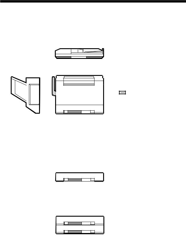
A. Exterior View
q Copyboard cover |
t Cassette |
w Power switch |
y Front door |
e Clip tray |
u Control panel |
r Multifeeder |
i Copyboard glass |
|
Figure 1-301 |
q Open/close lever |
r Heater switch |
w Copy density correction knob |
t Copy tray |
e Static eliminator cleaner |
y Static eliminator |
Figure 1-302
1-6 |
COPYRIGHT © 1997 CANON INC. |
CANON NP6218 REV. 0 MAY 1997 PRINTED IN JAPAN (IMPRIME AU JAPON) |

CHAPTER 1 GENERAL DESCRIPTION
B. Cross Section
1. Body
q No. 3 mirror |
!1Reflecting plate |
@1Transfer roller |
w No. 2 mirror |
!2No. 6 mirror |
@2Separation static eliminator |
e No. 1 mirror |
!3Developing cylinder |
@3Photosensitive drum |
r Scanning lamp |
!4Developing assembly |
@4Feeding assembly |
t Copyboard glass |
!5No. 5 mirror |
@5Cassette |
y Copyboard cover |
!6No. 4 mirror |
@6Fixing film |
u Lens |
!7Multifeeder tray |
@7Film tension roller |
i Exhaust fan |
!8Multifeeder pick-up roller |
@8Film pressure roller |
o Pre-exposure lamp |
!9Cassette pick-up roller |
@9Film drive roller |
!0Primary charging roller |
@0Registration roller |
#0Delivery roller |
|
Figure 1-303 |
|
COPYRIGHT © 1997 CANON INC. |
CANON NP6218 REV. 0 MAY 1997 PRINTED IN JAPAN (IMPRIME AU JAPON) |
1-7 |
CHAPTER 1 GENERAL DESCRIPTION
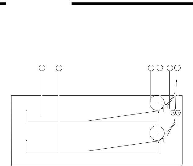
2. Cassette Feeding Module-A2
1 |
2 |
3 |
4 |
5 |
6 |
q Cassette 2 |
r Cassette 3 pick-up roller |
w Cassette 3 |
t Drive roller |
e Cassette 2 pick-up roller |
y Feeding roller |
|
Figure 1-304 |
1-8 |
COPYRIGHT © 1997 CANON INC. |
CANON NP6218 REV. 0 MAY 1997 PRINTED IN JAPAN (IMPRIME AU JAPON) |
CHAPTER 1 GENERAL DESCRIPTION
IV. OPERATION
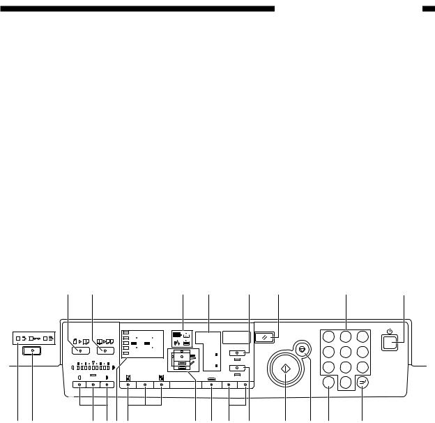
A. Control Panel
q Image Compose key |
!2 Start key |
w Page Separate key |
!3 Auto Ratio key |
e Warning indicator |
!4 Zoom key |
r Display |
!5 Paper Select key |
t % key |
!6 Cassette/Jam indicator |
y Reset key |
!7 Direct key |
u Keypad |
!8 Reduce/Enlarge key |
i Power switch |
!9 Copy density key |
o Interrupt key |
@0 AE key |
!0 Clear key |
@1 Sorter key |
!1 Stop key |
@2 Sorter indicator |
q w |
e r |
t y |
u |
i |
Max 200% |
|
|
1 2 3 |
|
|
A4 |
A3 |
A5 |
A4 |
Autom. Paper |
|
|
1:1 |
|
|
A3 |
|
A3 |
A4 |
A4 |
A5 |
A4 |
% |
Min 50% |
|
|
|
||
|
|
A4 R |
|
||
|
|
|
|
|
|
|
|
|
|
A5 |
Autom. Zoom |
|
|
|
|
A5 R |
|
|
|
|
|
|
|
A |
1:1 |
|
|
– Zoom + |
|
1 2 3
4 5 6
7 8 9
C 0
@2 @1 |
@0!9!8!7 |
!6 !5 !4 |
!3 |
!2 |
!1 !0 |
o |
Figure 1-401
COPYRIGHT © 1997 CANON INC. |
CANON NP6218 REV. 0 MAY 1997 PRINTED IN JAPAN (IMPRIME AU JAPON) |
1-9 |

CHAPTER 1 GENERAL DESCRIPTION
B. Operation Mode
Mode |
Description |
Remarks |
|
|
|
Image Composition |
Press to set/reset image composition mode. |
Only when an ADF |
mode |
|
(accessory) is installed. |
|
|
|
Page Separation |
Press to set/reset page separation mode. |
|
mode |
|
|
|
|
|
Interrupt mode |
Press to interrupt an ongoing copying |
|
|
session. |
|
|
|
|
Auto Ratio mode |
Press it to set/reset auto ratio mode. |
Only when an ADF |
|
|
(accessory) is installed. |
|
|
|
AE mode |
Press to set/re-set AE mode or user mode. |
|
|
|
|
Sort/staple |
Press it to select/reset sort, staple sort, or |
Only when an sorter |
sort/group mode |
group mode. |
(accessory) is installed. |
|
|
|
Table 1-401
1-10 |
COPYRIGHT © 1997 CANON INC. |
CANON NP6218 REV. 0 MAY 1997 PRINTED IN JAPAN (IMPRIME AU JAPON) |
CHAPTER 1 GENERAL DESCRIPTION
C. Making Two-Sided/Overlay Copies (manual)
You can make two-sided or overlay copies by manually feeding paper. You must, however, keep the following in mind when making such copies:
q Be sure to orient the paper the same way for both sides when turning it over. w Make sure that the paper has not absorbed moisture.
e Make sure that the paper has no curling.
r After copying on the first side, sufficiently cool the paper; then, correct any curling before feeding it for a second time.
t Use paper of 60 to 128 g/m2.
yCorrect any curling on postcards or thick paper (128 g/m2) before copying on the second side.
Figure 1-405
COPYRIGHT © 1997 CANON INC. |
CANON NP6218 REV. 0 MAY 1997 PRINTED IN JAPAN (IMPRIME AU JAPON) |
1-11 |

CHAPTER 1 GENERAL DESCRIPTION
D. User Mode
1. Outline
The copier provides user mode, which allows the user to change various settings or to make various adjustments on his/her own; see Table 1-402.
Menu No. Display |
Function |
Description |
Default settings |
1 |
Changing the auto |
You may set the auto clear time |
2 min |
|
clear time |
between 1 and 9 min in 1-min |
|
|
|
increments. Setting it to ‘0’ |
|
|
|
disables the function. |
|
2 |
Changing the auto |
You can set the auto power-off |
5 min |
|
power-off time |
time to either 2, 5, 10, 15, 30, 60, |
|
|
|
or 120 min. |
|
3 |
Fine adjusting |
You can correct a slight discrep- |
± 0% |
|
(zoom) |
ancy between original and copy |
|
|
|
sizes (direct); enlarge in X direc- |
|
|
|
tion and reduce in Y direction |
|
|
|
independent of each other. |
|
5 |
Turning on/off |
You may specify whether to |
On |
|
auto sort/non-sort |
evecute auto sort/non-sort. |
|
|
(with ADF* and |
|
|
|
sorter* installed) |
|
|
|
*Accessory |
|
|
6 |
Cleaning the feeder |
Use it to clean the pick-up |
|
|
(with ADF* installed) |
assembly of the ADF. |
|
|
Option |
|
|
9 |
Selecting a densi- |
You can specify either AE or |
AE |
|
ty adjustment |
manual for density adjustment for |
|
|
method for |
standard mode. |
|
|
standard mode |
|
|
0 |
Initializing user |
You can return settings changed |
|
|
mode |
in user mode to initial settings. |
|
Table 1-402
1-12 |
COPYRIGHT © 1997 CANON INC. |
CANON NP6218 REV. 0 MAY 1997 PRINTED IN JAPAN (IMPRIME AU JAPON) |
CHAPTER 1 GENERAL DESCRIPTION
2. Common Operations
a.Keys to Use in User Mode
•Clear Key
Use it to return to the previous step; or, use it to clear a setting entered by mistake when making mode settings.
•Start Key
Use it to accept a selected item when making user mode settings.
•AE Key
Use it to return to copy mode when making user mode settings.
b.Operation
1) Hold down the AE key for about 4 sec or more. |
|
• This will turn on the display, indicating “ |
”. |
2)Enter the menu number of each function using the keypad.
3)Press the Start key.
•The current setting of the respective function appears.
4)Enter a new setting using the appropriate key.
5)Press the start key.
•The copy count/ratio indictor turns on to indicate the user mode being changed.
•The setting of the respective user mode is changed.
6)Press the AE key.
•The copier returns to standby state.
3. Changing the Auto Clear Time ( |
) |
|
1) Hold down the AE key for 4 sec or more. |
|
|
• “ |
” appears on the display. |
|
2)Press the Start key.
•The display indicates the current setting (if initial, indicates ‘1-2’).
3)Enter a desired setting using the keypad.
•The display indicates the new setting (if 5 min, indicates ‘1-5’).
4) Press the Start key. “ |
” |
5)Press the AE key.
• The copier returns to standby state.
4. |
Changing the Auto Power-Off Time ( |
) |
|
|
1) |
Hold down the AE key for 4 sec or more. |
|
|
|
|
• “ |
” appears on the display. |
|
|
2) |
Enter ‘2’ using the keypad so that the display indicates “ |
”. |
||
3)Press the Start key.
• The display indicates the current setting (if initial, indicates ‘2-2’).
4)Enter a desired setting using the keypad.
COPYRIGHT © 1997 CANON INC. |
CANON NP6218 REV. 0 MAY 1997 PRINTED IN JAPAN (IMPRIME AU JAPON) |
1-13 |
CHAPTER 1 GENERAL DESCRIPTION
Auto power-off time (min) |
Settings |
|
|
2 |
2-1 |
|
|
5 |
2-2 |
|
|
10 |
2-3 |
|
|
15 |
2-4 |
|
|
30 |
2-5 |
|
|
60 |
2-6 |
|
|
120 |
2-7 |
|
|
Table 1-403
• The display indicates the new setting (if 10 min, indicates ‘2-3’).
5)Press the Start key.
• The auto power-off time is changed, and the display returns to “ |
”. |
6)Press the AE key.
• The copier returns to standby state.
Reference:
If you want to disable the auto power-off function, use service mode (See p. 10-109.).
5. |
Zoom Fine-Adjustment ( |
) |
|
1) |
Hold down the AE key for 4 sec or more. |
|
|
|
• The display indicates “ |
”. |
|
2) |
Enter ‘3’ using the keypad so that the display indicates “ |
”. |
|
3)Press the Start key.
• The display indicates ‘3-1’ suggesting the direction of adjustment.
Direction of adjustment |
Display |
|
|
X direction (horizontal) |
3-1 |
|
|
Y direction (vertical) |
3-2 |
|
|
Table 1-404
Further, the copy density indicator shows the current setting. (See Figure 1-406.)
4)Press the copy density key to adjust the reproduction ratio in X direction. (See Figure 1-406.)
5)Press the Start key.
•The reproduction ratio in X direction is fine-adjusted, and the display indicates ‘3-
2’.
Further, the copy density indicator shows the current setting. (See Figure 1-406.)
6)Press the Density key to adjust the reproduction ratio in Y direction. (See Figure 1- 406.)
1-14 |
COPYRIGHT © 1997 CANON INC. |
CANON NP6218 REV. 0 MAY 1997 PRINTED IN JAPAN (IMPRIME AU JAPON) |
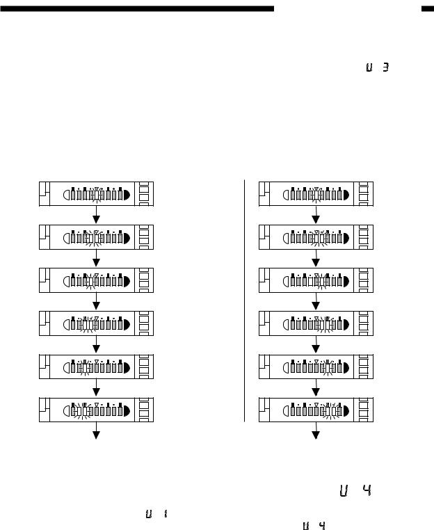
CHAPTER 1 GENERAL DESCRIPTION
7) Press the Start key. |
|
• The zoom reproduction is fine-adjusted, and the display returns to “ |
”. |
8)Press the AE key.
• The copier returns to standby state.
The fine-adjustment reproduction ratios as shown in the copy density display are as follows:
■ Zoom Fine-Adjustment (Reduce) |
■ Zoom Fine-Adjustment (Enlarge) |
Press the Lighter key. |
Press the Darker key. |
Initial setting |
Initial setting |
(±0%) |
(±0%) |
-0.2% |
+0.2% |
-0.4% |
+0.4% |
-0.6% |
+0.6% |
-0.8% |
+0.8% |
-1.0% |
+1.0% |
Figure 1-402
6. Turning On and Off the Auto Cassette Change Mechanism ( |
) |
1) Hold down the AE key for 4 sec or more.
• The display indicates “ |
”. |
|
2) Enter r using the keypad so that the display indicates “ |
”. |
|
3)Press the Start key.
• The display indicates the current setting (if initial setting, ‘4-1’).
State of auto cassette change function |
Settings |
|
|
On |
4-1 |
|
|
Off |
4-0 |
|
|
Table 1-405
COPYRIGHT © 1997 CANON INC. |
CANON NP6218 REV. 0 MAY 1997 PRINTED IN JAPAN (IMPRIME AU JAPON) |
1-15 |
Loading...