


 Loading...
FP B740 MP C530 MP C545 MP C555 MP C560
SERVICE MANUAL
Canon
REVISION 0
|
MultiPASS C530 |
H12-1592 |
120V |
CCSI |
|
||||
|
MultiPASS C530 |
H12-1596 |
120V |
CND/LTN |
|
MultiPASS C560 |
H12-1582 |
120V |
CCSI |
|
MultiPASS C560 |
H12-1586 |
120V |
CND/LTN |
|
|
|
|
|
|
|
|
|
|
JULY 1999 |
HY8-19AN-000 |
COPYRIGHT © 1999 CANON INC. |
CANON MultiPASS C530/C560 |
JULY 1999 PRINTED IN JAPAN (IMPRIME AU JAPON) |
Application
This manual has been issued by Canon Inc. for qualified persons to learn technical theory, installation, maintenance, and repair of products. This manual covers all localities where the products are sold. For this reason, there may be information in this manual that does not apply to your locality.
Corrections
This manual may contain technical inaccuracies or typographical errors due to improvements or changes in products. When changes occur in applicable products or in the content of this manual, Canon will release technical information as the need arises. In the event of major changes in the contents of this manual over a long or short period, Canon will issue a new editions of this manual.
The following paragraph does not apply to any countries where such provisions are inconsistent with local
law.
Trademarks
The product names and company names described in this manual are the registered trademarks of the individual companies.
Copyright
This manual is copyrighted with all rights reserved. Under the copyright laws, this manual may not be copied, reproduced or translated into another language, in whole or in part, without the written consent of Canon Inc.
Copyright © 1999 by Canon Inc.
CANON INC.
Office Imaging Products Technical Support Dept.
5-1 Hakusan 7-Chome, Toride-city, Ibaraki 302-0022, Japan
DTP System
This manual was produced on an Apple Macintosh® personal computer, final pages were printed on Canon SUPER LASER SHOT B406 PS.
All graphics were produced with Macromedia FreeHand®.
All documents and all page layouts were created with Adobe PageMaker®.
I. MEANING OF MARKS
The marks used in this manual have the following meanings.
Mark Meaning
States a precaution to be taken to prevent danger to personnel, damage to the product, or damage to electronic components by discharge of static electricity. for example.
States a precaution to be taken to prevent damage to electronic components by electrostatic discharge.
Informs you of fire-related cautions.
Informs you that the plug must be removed from the power outlet before starting an operation.
Gives useful information to understand descriptions.
NOTE
Indicates sections to be read to obtain more detailed information.
REFERENCE
I

II. ABOUT THIS MANUAL
This manual is divided into five parts, and contains information required for servicing the product.
Each of the above parts is further divided into the following four chapters:
Chapter 1: General Description
This part explains product specifications and the how to service the unit safely. It is very important, so please read it.
Chapter 2: Technical Reference
This part explains the technical theory of the product.
Chapter 3: Maintenance and Service
This part explains how to maintain the products for adjustment and troubleshooting and service operations and service switches.
Chapter 4: Appendix
This part explains the informations of the optional products and user data flow.
|
• For more details of user operations and user reports, see the separate volume of USER'S |
|
|
GUIDE. |
|
REFERENCE |
• Procedure for assembly/disassembly and greasing points are not given in this manual. See |
|
the illustrations in the separate volume of PARTS CATALOG. |
||
|
•Detailed description of each SSSW/parameter is not given in this manual except the new SSSWs/parameters added to this model.
See G3 Facsimile Service Data Handbook (supplied separately) for details them.
•See the G3 Facsimile Error Code List (Rev.1, supplied separately) for details of the error codes not shown in this manual.
•Detailed description of connector Locations and Signal Descriptions in not given in this manual.
See the Circuit Diagram for details them.
II

III. REVISION HISTORY
REVISION |
CONTENT |
|
|
0 |
Original |
III

IV. TABLE OF CONTENTS
Page |
Chapter 1: General Description |
|||
1 - 1 |
1. FEATURES |
|||
1 - 1 |
1.1 |
Overview |
||
1 - 2 |
2. SPECIFICATIONS |
|||
1 - |
2 |
2.1 |
General Specification |
|
1 - 2 |
2.2 |
Communication Specification |
||
1 - |
3 |
2.3 |
Color Communication Specification |
|
1 - |
4 |
2.4 |
Scanner Specification |
|
1 - |
6 |
2.5 |
Printer Specification |
|
1 - |
9 |
2.6 |
Copy Specification |
|
1 -10 |
2.7 |
Function |
||
1 -12 |
3. OVERVIEW |
|||
1 -12 |
3.1 |
External View |
||
1 -14 |
3.2 |
Operation Panel |
||
1 -19 |
3.3 |
Consumables |
||
1 -19 |
|
3.3.1 BJ cartridge and ink cartridge and BJ cartridge container |
||
1 -21 |
|
3.3.2 |
Print media |
|
1 -23 |
4. DIMENSIONS |
|||
1 -24 |
5. SAFETY & PRECAUTIONS |
|||
1 -24 |
5.1 |
Personnel Hazards |
||
1 -26 |
|
5.1.1 |
Electrical shock |
|
1 -26 |
|
5.1.2 |
High-temperature parts |
|
1 -27 |
|
5.1.3 |
Fire hazards |
|
1 -27 |
|
5.1.4 |
Moving parts |
|
1 -27 |
|
5.1.5 |
Preventing ink stains |
|
1 -28 |
5.2 |
General Cautions |
||
1 -28 |
|
5.2.1 |
Unit cautions |
|
1 -34 |
|
5.2.2 |
BJ cartridge cautions |
|
1 -45 |
|
5.2.3 |
Ink cartridge cautions |
|
1 -47 |
5.3 |
Servicing Cautions |
||
1 -47 |
|
5.3.1 |
Damage from static charge |
|
1 -47 |
|
5.3.2 |
Scanner unit |
|
1 -48 |
|
5.3.3 |
Print assembly |
|
1 -50 |
|
5.3.4 |
Paper feed section |
|
1 -50 |
|
5.3.5 |
Control boards |
|
1 -51 |
|
5.3.6 Detaching the outer covers |
||
1 -52 |
|
5.3.7 Attaching the operation panel sheet |
||
1 -53 |
5.4 |
Data-related precautions |
||
1 -54 |
|
5.4.1 |
Data in the image storage memory (DRAM) |
|
1 -55 |
|
5.4.2 |
Data in the control processing memory (SRAM) |
|
1 -56 |
|
5.4.3 |
Data in the EEPROM |
|
IV
1 -58 |
5.4.4 |
Replacing ROM |
1 -60 |
5.4.5 |
SPCNT board replacement precautions |
1 -61 |
5.4.6 Data initialization through service operation |
|
1 -62 |
5.5 Protective Mechanism |
|
1 -62 |
5.5.1 Data battery backup function |
|
1 -62 |
5.5.2 BJ cartridge maintenance features |
|
1 -63 |
5.5.3 |
Heat protection mechanism |
1 -63 |
5.5.4 |
Overcurrent protection |
1 -64 |
5.5.5 |
Lightning protection |
1 -64 |
5.5.6 |
Power leakage protection |
1 -65 |
6. QUALIFICATION REQUIRED FOR INSTALLATION WORK |
|
Chapter 2: Technical Reference
2 - 1 |
1. |
COMPONENT LAYOUT |
||
2 - 3 |
2. |
SCANNER MECHANISM |
||
2 - 6 |
3. |
PAPER SUPPLY MECHANISM |
||
2 -11 |
4. |
PRINTER SECTION |
||
2 -18 |
5. |
BJ CARTRIDGE |
||
2 -18 |
|
5.1 |
Structure |
|
2 -21 |
|
5.2 |
BJ Head Driver Block Diagram |
|
2 -23 |
|
5.3 |
Printing Signal |
|
2 -25 |
6. |
ELECTRIC CIRCUIT |
||
2 -25 |
|
6.1 |
Component Block Diagram |
|
2 -26 |
|
6.2 |
Circuit Board Components |
|
2 -29 |
|
6.3 |
Flow of Image Signals |
|
2 -34 |
7. |
COMMUNICATION SYSTEM OPERATIONS |
||
2 -34 |
|
7.1 |
FAX/TEL Switching |
|
2 -34 |
|
|
7.1.1 |
Settings |
2 -34 |
|
|
7.1.2 |
Parameters |
2 -35 |
|
7.2 |
Answering Machine Connection |
|
2 -35 |
|
|
7.2.1 |
Settings |
2 -35 |
|
|
7.2.2 |
Parameters |
2 -35 |
|
7.3 |
Manual/Auto Reception Switching |
|
2 -35 |
|
|
7.3.1 |
Settings |
2 -35 |
|
|
7.3.2 |
Parameters |
2 -36 |
8. |
NEW FUNCTION |
||
2 -36 |
|
8.1 |
High-speed Transmission |
|
2 -36 |
|
|
8.1.1 |
V.8/V.34 protocol |
2 -50 |
|
8.2 |
JBIG Image Compression Encoding Method |
|
2 -50 |
|
|
8.2.1 |
Outline of the JBIG image compression encoding method |
2 -51 |
|
|
8.2.2 |
Single progression sequential bi-level image compression method |
2 -52 |
|
|
8.2.3 |
Encoding method |
2 -59 |
|
|
8.2.4 |
Construction of image data with JBIG image compression encoding |
2 -60 |
|
|
8.2.5 |
Explanation of bi-level image header section (BIH) |
V
2 -61 |
|
8.2.6 |
Explanation and parameters for each symbol used in BIH |
2 -62 |
|
8.2.7 Explanation of bi-level image data (BID) section |
|
2 -62 |
|
8.2.8 |
Explanation and parameters for each symbol used in BID |
2 -64 |
8.3 |
Color Scanning Ability |
|
2 -64 |
|
8.3.1 |
Contact sensor specifications |
2 -65 |
|
8.3.2 |
Reading color documents |
2 -65 |
|
8.3.3 |
Reading black & white documents |
2 -66 |
8.4 |
MultiPASS Function |
|
2 -66 |
|
8.4.1 |
Specifications |
2 -68 |
|
8.4.2 |
Bi-directional centronics interface |
2 -69 |
8.5 |
Color Communications |
|
2 -69 |
|
8.5.1 |
Specifications |
2 -71 |
|
8.5.2 |
The JPEG encoding method |
2 -73 |
|
8.5.3 |
Image processing outline |
2 -74 |
|
8.5.4 ITU-T color transimission protocols |
|
2 -75 |
|
8.5.5 Conditions necessary for ITU-T color transmission |
|
2 -76 |
|
8.5.6 Operaions where other machine does not have color communications abillty |
|
2 -76 |
|
8.5.7 Conditions necessary for color reception |
|
2 -77 |
|
8.5.8 |
Specification for Color Communications |
Chapter 3: Maintenance & Service
3 - 1 |
1. MAINTENANCE LIST |
|
3 - 1 |
1.1 |
Consumables |
3 - 1 |
1.2 |
Cleaning |
3 - 2 |
1.3 |
Periodic Inspection |
3 - 2 |
1.4 |
Periodic Replacement Parts |
3 - 2 |
1.5 |
Adjustment Items |
3 - 3 |
1.6 |
General Tools |
3 - 3 |
1.7 |
Special Tools |
3 - 4 |
2. HOW TO CLEAN PARTS |
|
3 - 4 |
2.1 |
Main Unit Outer Covers |
3 - 4 |
2.2 |
Separation Roller |
3 - 4 |
2.3 |
Document Feed/Eject Roller |
3 - 4 |
2.4 |
Separation Guide |
3 - 4 |
2.5 |
Scanning Glass (Contact Sensor) |
3 - 4 |
2.6 |
White Sheet |
3 - 4 |
2.7 |
Printer Platen |
3 - 6 |
3. ADJUSTMENT |
|
3 - 6 |
3.1 |
CS LED Lights-on Duration Adjustment |
3 - 7 |
3.2 |
Vertical Alignment Correction |
3 -10 |
4. TROUBLESHOOTING |
|
3 -10 |
4.1 |
Troubleshooting Index |
3 -11 |
4.2 |
Errors Shown on the Display |
3 -11 |
|
4.2.1 User error message |
VI
3 -16 |
|
4.2.2 |
Error codes |
3 -24 |
4.3 |
Errors not Shown on the Display |
|
3 -24 |
|
4.3.1 |
General errors |
3 -25 |
|
4.3.2 |
Printing problem |
3 -27 |
|
4.3.3 |
Scanning problem |
3 -29 |
5. SERVICE SWITCHES |
||
3 -29 |
5.1 |
Hardware Switches |
|
3 -29 |
5.2 |
Service Data Setting |
|
3 -29 |
|
5.2.1 |
Service data overview |
3 -30 |
|
5.2.2 Service data registration/setting method |
|
3 -31 |
|
5.2.3 |
Service data setting |
3 -38 |
|
5.2.4 Explanation of service data |
|
3 -39 |
|
5.2.5 |
New SSSWs/parameters added to this model |
3 -43 |
6. TEST FUNCTIONS |
||
3 -43 |
6.1 |
User Test Print Functions |
|
3 -43 |
|
6.1.1 |
Nozzle check |
3 -44 |
6.2 |
Service Test Functions |
|
3 -44 |
|
6.2.1 |
Test mode overview |
3 -45 |
|
6.2.2 |
Test mode flowchart |
3 -46 |
|
6.2.3 |
D-RAM tests |
3 -46 |
|
6.2.4 |
CS tests |
3 -47 |
|
6.2.5 |
PRINT test |
3 -49 |
|
6.2.6 |
Modem and NCU tests |
3 -53 |
|
6.2.7 |
Faculty tests |
3 -58 |
7. SERVICE REPORT |
||
3 -58 |
7.1 |
Report Output Function |
|
3 -58 |
|
7.1.1 User report output functions |
|
3 -60 |
|
7.1.2 Service report output functions |
|
3 -68 |
8. WIRING DIAGRAM |
||
3 -68 |
8.1 |
Wiring Diagram |
|
3 -69 |
8.2 |
Connector Location and Signal Descriptions |
|
Chapter 4: Appendix
4 - 1 |
1. |
INSTALLATION |
|
4 - 1 |
|
1.1 |
Setting Up |
4 - 1 |
|
1.2 |
Checking Operations |
4 - 2 |
2. |
USER DATA FLOW |
|
4 - 2 |
|
2.1 |
USER DATA FLOW (by Operation Panel) |
4 - 6 |
|
2.2 |
Memory Reference Function Flow |
4 - 7 |
3. |
MAKER-CODE |
|
INDEX
VII
V. ILLUSTRATION INDEX
Page |
Chapter 1: General Description |
||||
1 - 5 |
Figure |
1- |
1 |
Scanning Range |
|
1 - |
7 |
Figure |
1- |
2 |
Printing Range |
1 - |
8 |
Figure |
1- |
3 |
Printing Range |
1 -12 |
Figure |
1- |
4 |
External View (1) |
|
1 -13 |
Figure |
1- |
5 |
External View (2) |
|
1 -14 |
Figure |
1- |
6 |
Operation Panel (1) |
|
1 -15 |
Figure |
1- |
7 |
Operation Panel (2) |
|
1 -16 |
Figure |
1- |
8 |
Operation Panel (3) |
|
1 -17 |
Figure |
1- |
9 |
Operation Panel (4) |
|
1 -18 |
Figure |
1- 10 |
Operation Panel (5) |
||
1 -19 |
Figure |
1- 11 |
Consumables (1) |
||
1 -20 |
Figure |
1- 12 |
Consumables (2) |
||
1 -21 |
Figure |
1- 13 |
Print Media (1) |
||
1 -22 |
Figure |
1- 14 |
Print Media (2) |
||
1 -23 |
Figure |
1- 15 |
Dimensions |
||
1 -24 |
Figure |
1- 16 |
Personnel Hazards (1) |
||
1 -25 |
Figure |
1- 17 |
Personnel Hazards (2) |
||
1 -43 |
Figure |
1- 18 |
Unpacking the BJ Cartridge |
||
1 -44 |
Figure |
1- 19 |
Ink Path Cartridge |
||
1 -45 |
Figure |
1- 20 |
Removing Cartridge Cap |
||
1 -46 |
Figure |
1- 21 |
Ink Outlet |
||
1 -48 |
Figure |
1- 22 |
Print Assembly Precautions |
||
1 -52 |
Figure |
1- 23 |
Opening the Upper Cover |
||
1 -52 |
Figure |
1- 24 |
Operation Panel Sheet |
||
1 -53 |
Figure |
1- 25 |
Memory IC and Backed up Devices |
||
1 -55 |
Figure |
1- 26 |
Attaching the Jumper Plug |
||
1 -57 |
Figure |
1- 27 |
Waste Ink Absorber |
||
1 -58 |
Figure |
1- 28 |
Attaching the Printer ROM |
||
1 -61 |
Figure |
1- 29 |
All Clear |
||
Chapter 2: Technical Reference
2 - 1 |
Figure |
2- |
1 |
Mechanical Layout |
2 - 2 |
Figure |
2- |
2 |
Electrical System Layout |
2 - 3 |
Figure |
2- |
3 |
Document Feed Section |
2 - 6 |
Figure |
2- |
4 |
Paper Feed Section |
2 - 8 |
Figure |
2- |
5 |
Paper Feed Motor Drive Switching |
2 - 9 |
Figure |
2- |
6 |
Paper Separation Mechanism |
2 -11 |
Figure |
2- |
7 |
Printer Section |
2 -13 |
Figure |
2- |
8 |
Purge Unit |
2 -13 |
Figure |
2- |
9 |
Pump Operation State Detection |
VIII
2 -17 |
Figure |
2- 10 |
Ink Empty Detection |
2 -19 |
Figure |
2- 11 |
Nozzle Arrangement |
2 -19 |
Figure |
2- 12 |
Black BJ Cartridge Structure |
2 -20 |
Figure |
2- 13 |
Color BJ Cartridge Structure |
2 -20 |
Figure |
2- 14 |
Photo BJ Cartridge Structure |
2 -22 |
Figure |
2- 15 |
BJ Head Driver Block Diagram (Black BJ Cartridge) |
2 -22 |
Figure |
2- 16 |
BJ Head Driver Block Diagram (Color “Multi Drop” BJ Cartridge) |
2 -23 |
Figure |
2- 17 |
Printing Sequence (Black BJ Cartridge/HQ Mode) |
2 -24 |
Figure |
2- 18 |
Printing Signals |
2 -25 |
Figure |
2- 19 |
Block Diagram |
2 -29 |
Figure |
2- 20 |
G3 Transmission Image Signal Flow |
2 -30 |
Figure |
2- 21 |
G3 Reception Image Signal Flow |
2 -31 |
Figure |
2- 22 |
Color G3 Transmission Image Signal Flow |
2 -32 |
Figure |
2- 23 |
Color G3 Reception Image Signal Flow |
2 -33 |
Figure |
2- 24 |
Color Image Scan Signal Flow |
2 -38 |
Figure |
2- 25 |
Typical Protocol |
2 -45 |
Figure |
2- 26 |
Late Start |
2 -46 |
Figure |
2- 27 |
Between-page Sequence |
2 -47 |
Figure |
2- 28 |
Mode Change |
2 -48 |
Figure |
2- 29 |
Image Transmission Speed Change from the Receiver |
2 -49 |
Figure |
2- 30 |
Image Transmission Speed Change from the Transmitter |
2 -50 |
Figure |
2- 31 |
Images |
2 -52 |
Figure |
2- 32 |
Encoder and Flow of JBIG Encoding |
2 -53 |
Figure |
2- 33 |
Model Templates |
2 -54 |
Figure |
2- 34 |
Positions of Pixels in Model Template |
2 -55 |
Figure |
2- 35 |
Study Table Study Example 1 |
2 -55 |
Figure |
2- 36 |
Study Table Study Example 2 |
2 -57 |
Figure |
2- 37 |
Arithmetic Encoding Conceptual Diagram |
2 -58 |
Figure |
2- 38 |
When Predictions are Continually Accurate |
2 -59 |
Figure |
2- 39 |
Construction of JBIG Image Data |
2 -59 |
Figure |
2-40 |
BIE Construction Diagram |
2 -60 |
Figure |
2- 41 |
BIH Construction Diagram |
2 -62 |
Figure |
2- 42 |
BID Construction Diagram |
2 -70 |
Figure |
2- 43 |
Sub Sampling |
2 -71 |
Figure |
2- 44 |
Discrete Cosine Transformation |
2 -72 |
Figure |
2- 45 |
JPEG Data Structure |
2 -73 |
Figure |
2- 46 |
Image Processing Out |
2 -74 |
Figure |
2- 47 |
ITU-T Color Protocol |
Chapter 3: Maintenance & Service
3 - |
5 |
Figure |
3- |
1 |
Cleaning Location |
3 - 6 |
Figure |
3- |
2 |
CS LED Lights-on Duration Adjustment Operation |
|
3 - |
7 |
Figure |
3- |
3 |
Printing the Test Pattern |
3 - 7 |
Figure |
3- |
4 |
Test Pattern Sample |
|
IX
3 - |
8 |
Figure |
3- |
5 |
Correct Test Pattern |
3 - |
8 |
Figure |
3- |
6 |
Sample Test Pattern with Vertical Misalignment |
3 - |
9 |
Figure |
3- |
7 |
Vertical Line Misalignment Correction Procedure |
3 -16 |
Figure |
3- |
8 |
Service Error Code Display |
|
3 -25 |
Figure |
3- |
9 |
Paper Feed Motor/Carriage Motor/Document Feed Motor Connector |
|
3 -26 |
Figure |
3- 10 |
Defective Pattern (Sample) |
||
3 -30 |
Figure |
3- 11 |
Service Data Setting Method |
||
3 -31 |
Figure |
3- 12 |
Service Data (page 1) |
||
3 -32 |
Figure |
3- 13 |
Service Data (page 2) |
||
3 -33 |
Figure |
3- 14 |
Service Data (page 3) |
||
3 -35 |
Figure |
3- 15 |
Service Data (page 4) |
||
3 -36 |
Figure |
3- 16 |
Service Data (page 5) |
||
3 -37 |
Figure |
3- 17 |
Service Data (page 6) |
||
3 -38 |
Figure |
3- 18 |
Bit Switch Display |
||
3 -38 |
Figure |
3- 19 |
How to Read Bit Switch Tables |
||
3 -43 |
Figure |
3- 20 |
Nozzle Check Pattern |
||
3 -45 |
Figure |
3- 21 |
Test Mode |
||
3 -46 |
Figure |
3- 22 |
D-RAM Test |
||
3 -47 |
Figure |
3- 23 |
Print Test Pattern Check |
||
3 -48 |
Figure |
3- 24 |
Print Pattern Sample |
||
3 -54 |
Figure |
3- 25 |
Sensor Tests |
||
3 -56 |
Figure |
3- 26 |
Operation Panel |
||
3 -59 |
Figure |
3- 27 |
Memory Clear List |
||
3 -61 |
Figure |
3- 28 |
System Data List (page 1 ~ page 4) |
||
3 -62 |
Figure |
3- 29 |
System Data List (page 5 ~ page 6) |
||
3 -63 |
Figure |
3- 30 |
System Dump List (1/2) |
||
3 -65 |
Figure |
3- 31 |
System Dump List (2/2) |
||
3 -66 |
Figure |
3- 32 |
Service Error Tx Report |
||
3 -67 |
Figure |
3- 33 |
Service Error Activity Report (receiving) |
||
3 -68 |
Figure |
3- 34 |
Wiring Diagram |
||
Chapter 4: Appendix
4 - 2 |
Figure |
4- |
1 |
User Menu Settings (1/4) |
4 - 3 |
Figure |
4- |
2 |
User Menu Settings (2/4) |
4 - 4 |
Figure |
4- |
3 |
User Menu Settings (3/4) |
4 - 5 |
Figure |
4- |
4 |
User Menu Settings (4/4) |
4 - 6 |
Figure |
4- |
5 |
Memory Reference Function Flow |
4 - 7 |
Figure |
4- |
6 |
Maker Code |
X

MultiPASS C530/C560 Chapter 1: General Description
1.FEATURES
1.1Overview
This product is a G3 transreceiving facsimile based on the ITU-T recommendations. It can be used in telephone networks.
*: This mark indicates a new function.
Picture Quality Color Printer
High quality printing can be accomplished with the Canon Bubble Jet (BJ) method using the maximum 720dpi × 360dpi resolution. Various kinds of media can be printed with the high speed of a maximum 4.5 pages per minute. The printing paper tray can hold up to 100 sheets of plain paper, 50 sheets of OHP film, or 10 back print films or envelopes.
*Plain paper fax which can transmit/receive in color
Conforming to ITU-T recommendations, this fax is able to transmit/receive in color. Due to containing extremely high-speed 14.4kbps (MultiPASS C530) / 33.6kbps (MultiPASS C560) modems, transmission time can be shortened. Pictures and photographs can both be send and received clearly by UHQ(Ultra High quality), Canon’s vivid image processing technology. Up to 20 letteror A4size sheets, or up to 10 legal-size sheets, can be set in the ADF. 12 one-touch dial entries and 100 speed dial entries can be registered, and group dial and broadcasting transmission can also be done. When paper and ink run out, the data is saved to memory, so there is no worry. When a external-phone is attached, fax communication and normal telephone reception are possible due to DRPD service and FAX/TEL switching.
BJ Cartridge |
See Page 2-18 |
Printing quality superior to photos is produced by use of BC-20 and BC-21e/BC-22e BJ cartridges.
*Out-of-Ink Function |
See Page 2-18 |
This machine has a function which detects when ink has run out. It also detects when the cartridges of machines equipped with color communications are out of ink. After printing each received page, the ink is ejected in front of a photo sensor in order to detect the presence/absence of remaining ink.
Copy Function
This machine can be used as a 360dpi × 360 dpi high resolution full color copier. With a monochrome document (including half-tone), up to 99 pages can be copied at one time at the speed of a maximum of 3 pages/minute.
Full Color & 256 Gradation Grayscale Scanner |
See Page 2-33 |
Using graphics or OCR software which conforms to the TWAIN standard, full color and 256-gradation grayscale images with a quality of 30dpi ~ 600 dpi can be read into a computer. Reading in can be done at a resolution of 300dpi, and can be enhanced to 600dpi using the included MultiPASS Desktop Manager.
PC Fax
By connecting this machine to a computer, a fax can be transmitted from the included MultiPASS Desktop Manager or from a Windows application, and a received image can be saved to the computer asis without printing it out.
1-1

MultiPASS C530/C560 Chapter 1: General Description
2.SPECIFICATIONS
2.1General Specification
|
Type |
|
Desktop |
|
|
Body colour |
|
Art gray |
|
|
|
|
|
|
|
Power source |
|
98 ~ 132V AC, 48 ~ 62 Hz, |
|
|
|
|
|
|
|
Power consumption |
|
standby 6.9 W (C560) 6.1 W (C530) |
|
|
|
|
Max. 37.9 W (when 100% black copy) |
|
|
|
|
|
|
|
Usage environment. |
|
50.0°F ~ 90.5°F (10°C ~ 32.5°C), 20%~85% RH, 532 ~ 760 |
|
|
|
|
mmHg (709 ~ 1013 hPa) |
|
|
|
|
Horizontal |
±3° or less |
|
|
|
|
|
|
Operating noise |
|
Measured in accordance with ISO standards |
|
|
|
|
Operating |
:47 dB(A) or less |
|
|
|
||
|
Dimensions (W D H) |
14.41" × 12.76" × 8.19" (366 mm × 324 × 208 mm) |
||
|
|
|
(Not including Trays) |
|
|
|
|
|
|
|
Weight |
|
11.24 lbs (5.1 kg) |
Including trays |
|
|
|
||
2.2 Communication Specification |
|
|||
|
|
|
|
|
|
Applicable lines |
|
PSTN (Public Switched Telephone Network) |
|
|
|
|
|
|
|
Applicable Services |
|
DRPD (Distinctive Ring Pattern Detection) |
|
|
|
|
|
|
|
Handset |
|
None |
|
|
|
|
|
|
|
Transmission method |
|
Half-duplex |
|
|
|
|
||
|
Transmission control protocol |
ITU-T T30 binary protocol/ECM protocol/ |
||
|
|
|
ITU-T V.8 protocol/V.34 protocol/ECM protocol* |
|
|
|
|
|
|
|
Modulation method |
|
|
|
|
G3 image signals |
ITU-T V.27ter (2.4k, 4.8k bps) |
||
|
|
|
ITU-T V.29 (7.2k, 9.6k bps) |
|
|
|
|
ITU-T V.33 (12k, 14.4k bps) |
|
|
|
|
ITU-T V.17 (TC7.2k, TC9.6k, 12k, 14.4k bps) |
|
|
|
|
ITU-T V.34 (2.4k, 4.8k, 7.2k, 9.6k, 12k, 14.4k, 16.8k, 19.2k, |
|
|
|
|
21.6k, 24k, 26.4k, 28.8k, 31.2k, 33.6k bps)* |
|
|
G3 procedure signals |
ITU-T V.21 (No.2) (300bps) |
||
|
|
|
ITU-T V.8 300bps* |
|
|
|
|
ITU-T V.34 600 bps, 1200 bps* |
|
|
|
|
(With automatic fallback function) |
|
|
|
|
||
|
Coding |
Black/white ITU-T T.4 Coding method (MH, MR) |
||
|
|
|
ITU-T T.6 Coding method (MMR) |
|
|
|
|
ITU-T T.82/T.85 Coding method (JBIG) |
|
|
|
Color |
ITU-T T.81 Coding method (JPEG) |
|
|
|
|
|
|
|
Error correction |
|
ITU-T T30 (ECM) |
|
|
|
|
|
|
|
Canon express protocol (CEP) |
None |
|
|
* MultiPASS C560 only
1-2
MultiPASS C530/C560 Chapter 1: General Description
Time required for transmission protocol |
|
|
||
|
|
Pre-message |
Post-message |
Post-message *3 |
|
Protocol |
Protocol *1 |
Protocol *2 |
|
|
Mode |
|
(between pages) |
(after pages) |
|
|
|
|
|
|
G3 standard |
approx.18 sec. |
approx.4 sec. |
approx.4 sec. |
|
V.8/V.34*4 |
approx.8 sec. |
approx.2 sec. |
approx.2 sec. |
*1 Time from when other facsimile is connected to the line until image transmission begins.
*2 Post-message (between pages): Time from after one document has been sent until transmission of the next document starts if several pages are transmitted.
*3 Post-message (after last pages): Time from after image transmission is completed until line is switched from facsimile to telephone.
*4 MultiPASS C560 only
Minimum transmission time |
10 msec (G3), 0 msec (G3, ECM) |
Transmission output level |
from 0 to -15 dBm |
|
|
Receive input level |
from -3 to -43 dBm |
|
|
Modem IC |
R288F-26 (MultiPASS C560) |
|
FM214 (MultiPASS C 530) |
|
|
2.3 Color Communication Specification
ITU-T recommendation |
ITU-T T.30 |
ANNEX E (JPEG Color Fax) |
|
T.4 ANNEX E (JPEG Header) |
|
|
T.42 (Color space for Color Fax) |
|
|
T.81 |
(JPEG) |
Scanning Document size |
A4 |
|
Printing paper size |
A4 |
|
Resolution |
200×200 dpi |
|
Picture element |
8 bit |
|
Coding |
JPEG |
|
Color space |
CIELAB |
|
Illuminant Data |
CIE Standard Illuminant D50 |
|
Sub sample |
4:1:1 (=Lab) |
|
For details Color Communication, see 8.5 Color communication on page 2-69.
REFERENCE
1-3

MultiPASS C530/C560 Chapter 1: General Description
2.4 Scanner Specification
Type |
|
Sheets |
|
|
|
ADF capacity |
|
Max. 20 sheets (A4/Letter) |
|
||
|
|
|
Max. 10 sheets (Legal) |
|
|
|
|
|
|
||
Effective scanning width |
Letter/Legal |
8.42" (214 mm) |
|||
|
|
|
A4 |
8.19" (208 mm) |
|
|
|
|
|
||
Scanning method |
Contact sensor scanning method |
|
|||
|
|
|
|
||
Scanning line density & Scanning speed |
|
|
|||
Operation |
Mode |
Line density |
Motor step |
Scanning speed |
|
|
|
|
|
interval |
|
|
|
|
|
|
|
FAX |
Standard |
8 dot/mm × 3.85 line/mm |
150 dpi/step |
5 msec/line (Direct TX) |
|
|
|
|
(203.2 dpi × 97.79 dpi) |
|
3.3 msec/line (Memory TX) |
|
|
Fine |
8 dot/mm × 7.7 line/mm |
300 dpi/step |
3.3 msec/line |
|
|
|
(203.2 dpi × 195.58 dpi) |
|
|
Scanner |
Text (Binary) |
150 dpi or less |
150 dpi/step |
5 msec/line |
|
|
|
|
151~300 dpi |
300 dpi/step |
3.3 msec/line |
|
|
|
301~600 dpi |
600 dpi/step |
3.3 msec/line |
|
|
Gray scale |
150 dpi or less |
150 dpi/step |
5 msec/line |
|
|
|
151~300 dpi |
300 dpi/step |
3.3 msec/line |
|
|
|
301~600 dpi |
600 dpi/step |
3.3 msec/line |
|
|
Full color |
150 dpi or less |
150 dpi/step |
9.9 msec/line |
|
|
|
151~300 dpi |
300 dpi/step |
9.9 msec/line |
|
|
|
301~600 dpi |
600 dpi/step |
9.9 msec/line |
Copy |
B&W |
360 dpi |
600 dpi/step |
3.3 msec/line |
|
|
|
Full color |
360 dpi |
600 dpi/step |
9.9 msec/line |
|
|
|
|
||
Scanner gradations |
grayscale; |
8 bit, 256 gradations |
|||
|
|
|
color; |
R,G,B (8 bits each) full color capability |
|
|
|
|
|
|
|
TWAIN |
|
Yes |
|
|
|
|
|
|
|
||
Scanning density adjustment |
3 density level |
|
|||
|
|
|
|
||
Image modes |
Halftone (PHOTO mode) |
|
|||
|
|
|
|||
Halftone (fax and copy) |
64-gradation error diffusion system (UHQ) |
||||
|
|
|
|
|
|
Prescan |
|
Yes |
|
|
|
1-4
MultiPASS C530/C560 Chapter 1: General Description
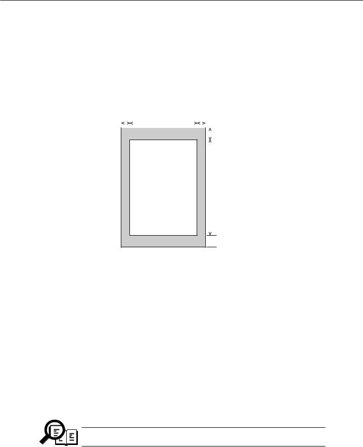
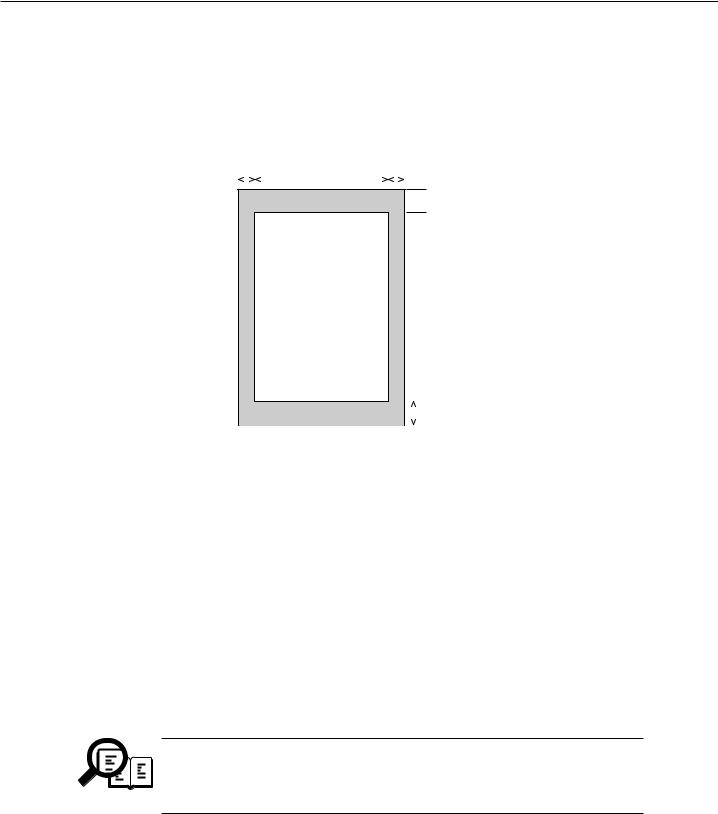
Scanning range
Sheet dimensions (W × L) |
|
8.50" × 39.3" (216 mm × 1000 mm) |
|||||||||
Maximum |
|
||||||||||
Minimum |
|
3.5" × 1.75" (88.9 mm × 44.5 mm) |
|||||||||
Thickness |
|
|
|
|
|
|
|
|
|
||
multiple pages: |
|
0.003" ~ 0.005" (0.08 mm ~ 0.13 mm) |
|||||||||
|
|
|
|
75~90 g/m2 |
|
|
|
|
|
|
|
single page: |
|
0.003" ~ 0.017" (0.08 mm ~ 0.43 mm) |
|||||||||
|
|
|
|
75~340 g/m2 |
|
|
|
|
|
|
|
Document leading edge |
|
|
|
|
|
|
|
||||
|
|
3 |
|
1 |
|
4 |
|
|
|
|
|
|
|
|
|
|
|
|
|||||
|
|
|
|
|
|
|
|
|
|
|
|
|
|
|
|
|
|
|
|
|
|
|
|
|
|
|
|
|
|
|
|
|
|
|
|
|
|
|
|
SCANNING |
|
|
|
|
|
5 |
|
|
|
|
|
DROP OUT RANGE |
|
|
|||||
|
|
|
|
|
|
|
|
|
|
|
|
SCANNING RANGE |
|
2 |
|
|
|
 6
6
Document trailing edge
Figure 1-1 Scanning Range
Item |
A4 |
Letter |
Legal |
|
1 |
Effective scanning width |
8.09"~8.23" |
8.31"~8.46" |
8.31"~8.46" |
|
|
(205.5~209 mm) |
(211.0~215 mm) |
(211.0~215 mm) |
2 |
Effective scanning length |
11.54" |
10.84" |
13.84" |
|
|
(289~297 mm) |
(271.4~279.4 mm) |
(347.6~355.6 mm) |
3 |
Left margin |
0.04" ±0.14" |
0.04" ±0.14" |
0.04" ±0.14" |
|
|
(1.0 mm ±3.5 mm) |
(1.0 mm ±3.5 mm) |
(1.0 mm ±3.5 mm) |
4 |
Right margin |
0.04" ±0.14" |
0.04" ±0.14" |
0.04" ±0.14" |
|
|
(1.0 mm ±3.5 mm) |
(1.0 mm ±3.5 mm) |
(1.0 mm ±3.5 mm) |
5 |
Top margin |
0.08" ±0.08" |
0.08" ±0.08" |
0.08" ±0.08" |
|
|
(2.0 mm ±2.0 mm) |
(2.0 mm ±2.0 mm) |
(2.0 mm ±2.0 mm) |
6 |
Bottom margin |
0.08" ±0.08" |
0.08" ±0.08" |
0.08" ±0.08" |
|
|
(2.0 mm ±2.0 mm) |
(2.0 mm ±2.0 mm) |
(2.0 mm ±2.0 mm) |
Units are inches with mm shown in parentheses.
Document scanning width “A4/LTR” is set in service data #1 SSSW SW06, bit4.
NOTE
1-5

MultiPASS C530/C560 Chapter 1: General Description
2.5 Printer Specification
Printing method |
Bubble-jet ink on-demand |
|
BJ Cartridge |
|
|
Products name |
BC-20 Black BJ cartridge/BC-21e Color BJ cartridge/BC-22e |
|
|
Photo Color BJ cartridge |
|
Product code |
F45-0561/F45-1301/F45-1311 |
|
Print head |
128 nozzles/136 nozzles (Y:24, M:24, C:24, Bk:64)/136 nozzles |
|
Ink cartridge (Ink tank) |
None/BCI-21 Color or BCI-21 Black/None |
|
Storage conditions |
Temperature |
32.0°F ~ 95.0°F (0°C ~ 35°C) |
|
Humidity |
35% ~ 85% RH |
|
|
|
Ink Cartridge |
|
|
Products name |
BCI-21 Black Ink Cartridge/BCI-21 Color Ink Cartridge |
|
Product code |
F47-0731/F47-0741 |
|
Ink contains |
9 ml/5 ml each of YMC |
|
|
|
|
Ink detection |
Interrupter Sense Black ink/Color ink (Detects separately) |
|
|
|
|
Printing speed |
Black |
Approx. 5 pages/minute (in case of character print) |
|
Color |
Approx. 1 page/minute |
|
|
|
Printing resolution |
360 dpi × 360 dpi (Normal print) |
|
|
180 dpi × 180 dpi (Economy print*) |
|
*Printing in a checkered pattern without printing vertical and horizontal adjacent dots. |
||
|
|
|
Paper output tray stacking |
Approx. 50 sheets (when using the recommended paper) |
|
|
Approx. 20 sheets (when raised output guides) |
|
|
|
|
Paper tray |
|
|
Paper supply method Number of paper tray Paper capacity
ASF (Auto Sheet Feeder)
1tray : Legal/Letter/A4 (Universal ) Max. 0.40" (10 mm) thickness plain paper (Approx. 100 sheets)
Recommended paper
Canon Copier LTR/LGL Premium Paper
Weight |
75 g/m2 |
Paper size |
Letter, Legal |
Manufactured by |
BOISE CASCADE |
PLOVER BOND |
|
Weight |
75 g/m2, 90 g/m2 |
Paper size |
Letter |
Manufactured by |
FOX RIVER |
XEROX 4024 |
|
Weight |
75 g/m2, 90 g/m2 |
Paper size |
Letter, Legal |
Manufactured by |
XEROX |
|
|
1-6
MultiPASS C530/C560 Chapter 1: General Description
Printing range (Black & White FAX)
Paper dimensions (W × L) |
|
8.50" × 10.98" (216 mm × 279 mm) |
||||||
Letter |
|
|||||||
Legal |
|
8.50" × 14.02" (216 mm × 356 mm) |
||||||
A4 |
|
8.27" × 11.69" (210 mm × 297 mm) |
||||||
Paper leading edge |
|
|
|
|
||||
|
|
2 |
|
1 |
|
3 |
|
|
|
|
|
|
|||||
|
|
|
|
|
|
|
|
|
|
|
|
|
|
|
|
|
|
PRINTING DROP OUT RANGE  4
4
PRINTING RANGE
|
|
|
|
5 |
|
|
|
|
|
|
|
|
|
|
|
|
Paper trailing edge |
|
|
|
|
|
|
|
Figure 1-2 Printing Range |
|
|||||
Item |
A4 |
Letter |
Legal |
||||
|
|
|
|
|
|||
1 Effective printing width |
8.00" |
8.00" |
|
8.00" |
|||
|
(203.2 mm) |
(203.2 mm) |
(203.2 mm) |
||||
2 Left margin |
0.13"±0.06" |
0.25"±0.06" |
0.25"±0.06" |
||||
|
(3.4±1.5 mm) |
(6.4±1.5 mm) |
(6.4±1.5 mm) |
||||
3 Right margin |
0.13"±0.06" |
0.25"±0.06" |
0.25"±0.06" |
||||
|
(3.4±1.5 mm) |
(6.4±1.5 mm) |
(6.4±1.5 mm) |
||||
4 Top margin |
0.12"±0.06" |
0.12"±0.06" |
0.12"±0.06" |
||||
|
(3.0±1.5 mm) |
(3.0±1.5 mm) |
(3.0±1.5 mm) |
||||
5 Bottom margin |
0.27"±0.12" |
0.27"±0.12" |
0.27"±0.12" |
||||
|
(7.0±3.0 mm) |
(7.0±3.0 mm) |
(7.0±3.0 mm) |
||||
Units are inches with mm shown in parentheses.
• The header and footer are printed in the printing range.
• The shaded area is included in the left and right margin errors of the paper trailing edge.
NOTE • The printing range is set in user data “PRINTER SETTINGS”, “PAPER SIZE” .
1-7
MultiPASS C530/C560 Chapter 1: General Description
Printing range (Color FAX & Printer mode)
Plain paper and Special media (Color FAX & Printer mode)
W L = Min. 7.17 1012 inch(182 257 mm) |
|
|
|
|
Max. 8.5 14.0 inch(216 356 mm) |
|
|
|
|
|
W |
|
Feed direction |
|
c |
d |
|
|
|
|
|
|
||
a |
e |
|
a = (Plain paper , etc.) |
e = 0.63 inch/16.0 mm (BC-20) |
|
|
|||
|
|
|
0.12 inch/3.0 mm |
0.81 inch/20.5 mm (BC-21e) |
|
|
|
(Fabric sheet only) |
1.00 inch/25.4 mm (BC-22e) |
|
|
|
1.5 inch/38.1 mm |
|
|
|
|
b = 0.27 inch |
f = 0.93 inch/23.5 mm |
|
|
|
7 mm |
|
|
|
L |
c = (A4) |
|
|
|
|
|
|
|
|
|
0.13 inch/3.4 mm |
|
|
|
|
(LTR, LGL) |
|
|
|
|
0.25 inch/6.4 mm |
|
b |
f |
|
: Recommended printing area |
|
|
|
|
|
|
|
|
|
: Printable area |
|
|
|
|
(contains recomended printing area) |
|
Envelopes |
|
|
|
|
W L = (COM #10) |
|
|
|
|
9.48 4.17 inch(241 106 mm) |
|
|
|
|
(DL) |
|
|
|
|
8.66 4.33 inch(220 110 mm) |
|
|
|
|
|
W |
|
|
|
c |
|
|
d |
|
a |
|
|
e |
|
|
|
|
|
|
|
|
|
L |
|
b |
|
|
f |
|
|
|
|
|
|
a = |
0.12 inch/3.0 mm |
|
Feed direction |
|
|
|
|
|
|
b = |
0.28 inch/7 mm |
|
|
|
c = |
0.27 inch/6.4 mm |
|
|
|
d = |
(COM #10) |
|
|
|
|
1.24 inch/31.4 mm |
|
|
|
|
(DL) |
|
|
|
|
0.41 inch/10.4 mm |
|
|
|
e = |
0.81 inch/20.5 mm |
|
|
|
f = |
0.93 inch/23.5 mm |
|
|
|
Figure 1-3 Printing Range
1-8

MultiPASS C530/C560 Chapter 1: General Description
2.6 Copy Specification
Color copy |
Yes |
|
|
Multiple copy |
99 copies (Black & white mode only) |
||
|
|
|
|
Copy mode |
|
|
|
|
Black & white |
B&W TEXT, B&W PHOTO |
|
|
Color |
COLOR FINE, COLOR DRAFT, |
|
|
|
COLOR SNAPSHOT |
|
|
|
|
|
Copy resolution |
|
|
360 dpi × 360 dpi (direct copy) |
|
Scanning |
Black & white |
|
|
|
|
8 dot/mm × 7.7 line/mm (memory copy) |
|
|
Color |
360 dpi × 360 dpi (FINE or SNAPSHOT) |
|
|
|
180 dpi × 360 dpi (DRAFT) |
|
Printing |
360 dpi × 360 dpi |
|
|
|
|
|
Copy magnification ratio |
100%, 90%, 80%, 70% |
|
|
|
|
|
|
1-9

MultiPASS C530/C560 Chapter 1: General Description
2.7 Function
Dialling |
|
|
Manual dialling |
Numeric button |
|
Auto dialing |
Max. 120 digits |
|
|
One-touch:12, Coded speed:100, Numeric button:1 |
|
Group dial |
Max.111 locations |
|
Redial |
Numeric button redial function (Max. 120 digits) |
|
|
|
|
Transmission |
|
|
Broadcast transmission |
Max. 113 locations (One-touch:12, Coded speed:100, Numeric |
|
|
button:1) |
|
Delayed transmission |
Yes (PC Assisted) Max. 30 reservation |
|
Confidential Tx/Rx |
None |
|
Relay broadcasting originating |
None |
|
Relay broadcasting |
None |
|
|
|
|
Reception |
|
|
Dual Access |
|
Yes |
FAX/TEL switching |
|
Yes |
Method |
|
CNG, ROT(Re-Order Tone) detection |
Message |
|
None |
Pseudo CI |
|
None |
Pseudo ring |
|
Yes |
Pseudo ringback tone |
|
Yes |
Reduction settings for reception |
|
Yes |
Automatic reduction of reception images |
Yes (100% ~ 70%) |
|
Built-in Answering machine |
|
None |
Answering machine connection |
|
Yes (Telephone answering priority type) |
Remote reception |
|
Yes (Remote ID method) |
Memory lock reception |
|
None |
Reception printing in reverse order |
None |
|
|
|
|
Polling |
|
|
Polling transmission |
|
None |
Polling reception |
|
None |
|
|
|
1-10

MultiPASS C530/C560 Chapter 1: General Description
Others |
|
Closed network |
None |
Direct mail prevention |
None |
Reception printing in reverse order |
None |
Memory box |
None |
Memory backup |
|
Backup contents |
Dial registration data, User data, Service data, |
|
Time |
Backup IC |
256 kbit SRAM for control |
Backup device |
Lithium battery 3.0V DC/220 mAh |
Battery life |
Approx. 5 years |
Image data backup |
None |
Image Memory |
Approx. 6.6 MB (MultiPASS C560) |
|
Approx. 672 KB (MultiPASS C530) |
Activity management |
Yes |
a) User report |
|
Activity management report (Every 20 transactions : always transmission and reception together) Activity report (sending/receiving)
One-touch speed dialling list Coded speed dialling list Group dialling list
Memory clear list User’s data list Document memory list Multi activity report
b) Service report
System data list System dump list Error list
Transmitting terminal identification |
Yes |
Time |
|
Management data |
Y e a r / m o n t h / d a t e / d a y / h o u r / m i n u t e ( 2 4 h o u r |
|
display) |
Precision |
±90 sec per month |
Display |
1 row × 16 digits |
Completion stamp |
None |
Program button |
None |
Hook button |
Yes |
Telephone exchange function |
None |
Speaker phone |
None |
Demo print function |
None |
HELP function |
None |
|
|
1-11
MultiPASS C530/C560 Chapter 1: General Description
3.OVERVIEW
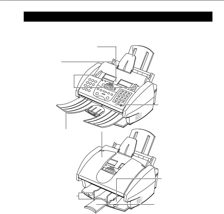
3.1External View
Front View
AUTOMATIC DOCUMENT FEEDER (ADF)
AND PRINTER COVER
Holds documents to be scanned.
PAPER GUIDE
Keeps print media in position. Adjust to the width of the print media.
DOCUMENT GUIDES  Keep the document in position when being scanned. Adjust to the width of the document.
DOCUMENT TRAY  When open, holds scanned
documents as they exit the MultiPASS. When closed, serves as a cover for the operation panel.
PAPER OUTPUT GUIDES Hold high resolution paper when using the BC-22e Photo BJ cartridge. Also hold banner paper.
 DOCUMENT SUPPORT Holds documents as they feed into the Automatic Document Feeder (ADF).
 PAPER REST Supports print media
stacked in the multi-purpose tray.
 MULTI-PURPOSE TRAY Holds plain paper and
  other print media.
OPERATION PANEL
Use to control the
MultiPASS.
OUTPUT TRAY
Holds printed pages as they exit the MultiPASS.
OUTPUT TRAY EXTENSION Holds printed pages as they exit the MultiPASS.
Figure 1-4 External View (1)
1-12

MultiPASS C530/C560 Chapter 1: General Description
Back View
POWER CORD
CONNECTOR
Inside View
 (CARTRIDGE) BUTTON
  Press this button to move
the cartridge holder to its center position for installing or replacing the BJ cartridge or BJ tank.
PAPER THICKNESS LEVER
Adjust for the type of print media you are using.
PARALLEL INTERFACE
PORT

 TELEPHONE JACK

 EXTENSION PHONE/
ANSWERING MACHINE/ DATA MODEM JACK

 TELEPHONE LINE JACK
 PRINTER COVER
CARTRIDGE
HOLDER
Figure 1-5 External View (2)
1-13
MultiPASS C530/C560 Chapter 1: General Description
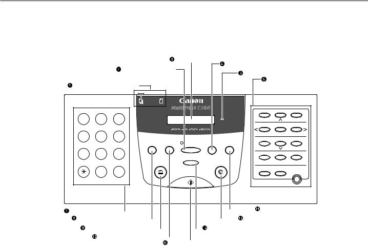
3.2 Operation Panel |
|
|
|
|
|
|
|
||
Operation Panel |
|
|
|
|
|
|
|
||
|
|
|
LCD DISPLAY |
Receive Mode BUTTON |
|
||||
|
|
Color/B&W BUTTON |
|
|
|
||||
|
|
|
|
Alarm LIGHT |
|
|
|||
|
|
|
|
|
|
|
|
||
|
|
|
|
|
|
|
ONE-TOUCH SPEED |
||
DOCUMENT FEED LEVER |
|
|
|
|
DIALING/SPECIAL |
||||
|
|
|
|
|
|
|
FUNCTION BUTTONS |
||
1 |
ABC |
DEF |
|
|
|
01 |
02 |
|
03 |
2 |
3 |
|
|
Alarm |
Data Registration |
|
|
||
|
|
|
|
|
|
04 |
05 |
|
06 |
GHI |
JKL |
MNO |
|
|
|
|
|
|
|
4 |
5 |
6 |
|
|
|
Memory Reference |
Space |
+ |
|
|
|
|
07 |
08 |
|
09 |
|||
|
|
|
Redial /Pause Coded Dial |
Color / B&W |
Receive Mode |
|
|||
PRS |
TUV |
WXY |
Copy |
|
|
|
|||
|
|
|
|
Report |
|
|
|||
7 |
8 |
9 |
|
|
|
|
|
|
|
|
Resolution |
|
10 |
11 |
|
12 |
|||
|
|
|
|
|
|
||||
|
|
|
|
|
|
|
|
|
|
|
OPER |
SYMBOLS |
Hook |
|
Stop |
Cleaning |
Clear |
|
|
|
|
|
|
|
|
||||
|
0 |
# |
|
|
|
Function |
Set |
|
|
|
|
Start / Scan |
|
|
|
|
Resume |
||
Tone |
|
|
|
|
|
|
|
|
|
NUMERIC BUTTONS |
|
|
|
|
|
|
|
|
|
|
|
|
|
|
Copy BUTTON |
|
|
|
|
|
|
|
|
|
|
|
|
|
|
|
|||
|
|
|
|
|
|
|
|
|
|
|
|
|
|
|
|
|
Redial/Pause BUTTON |
|
|
|
|
|
|
|
|
|
Stop BUTTON |
||||||
|
|
|
|
|
|
|
|
|
||||||||
Hook BUTTON |
|
|
|
|
|
|
Resolution BUTTON |
|
|
|||||||
|
|
|
|
|
|
|
|
|
The model name varies |
|||||||
|
|
|
|
|
|
|||||||||||
Coded Dial BUTTON |
|
|
|
|
|
|
|
|
|
|
|
depending on the model |
||||
|
|
|
|
|
|
|
|
|
|
|||||||
|
|
|
|
|
|
|
Start/Scan BUTTON |
|
you have purchased. |
|||||||
|
|
|
|
|
|
|
|
|
||||||||
uDocument Feed Lever
Sets the Automatic Document Feeder (ADF) to  (automatic document feed) for feeding multipage documents, or to
  (manual document feed) for feeding single sheets.
vColor/B&W Button
Sets the unit for color or black & white transmission or copying. For color transmission or color copying, press this button to turn on its light.
wLCD Display
Displays messages and prompts during operation, and displays selections, text, numbers, and names when registering information.
xReceive Mode Button
Selects the receive mode.
Figure 1-6 Operation Panel (1)
1-14

MultiPASS C530/C560 Chapter 1: General Description
yAlarm Light
Flashes when an error occurs, or when the MultiPASS is out of paper or ink.
UOne-Touch Speed Dial/Special Function Buttons
Dial fax/telephone numbers registered for one-touch speed dialing. Also used to perform special functions.
VNumeric Buttons
Enter numbers when dialing or registering numbers. Also enter letters when registering names.
WRedial/Pause Button
Redials the last number that was dialed using the numeric buttons (regular dialing). Also enters pauses between or after the telephone/fax number when dialing or registering numbers.
XHook Button
Engages or disengages the telephone line.
at Coded Dial Button
Press this button and a two-digit code to dial a fax/telephone number that you have registered for coded speed dialing.
ak Start/Scan Button
Starts sending, receiving, scanning, and copying.
al Resolution Button
Selects the resolution the MultiPASS uses for the document you are sending or copying.
am Stop Button
Cancels sending, receiving, registering data, copying and other operations, and returns the MultiPASS to standby mode.
an Copy Button
Sets the MultiPASS to make copies.
Figure 1-7 Operation Panel (2)
1-15
MultiPASS C530/C560 Chapter 1: General Description
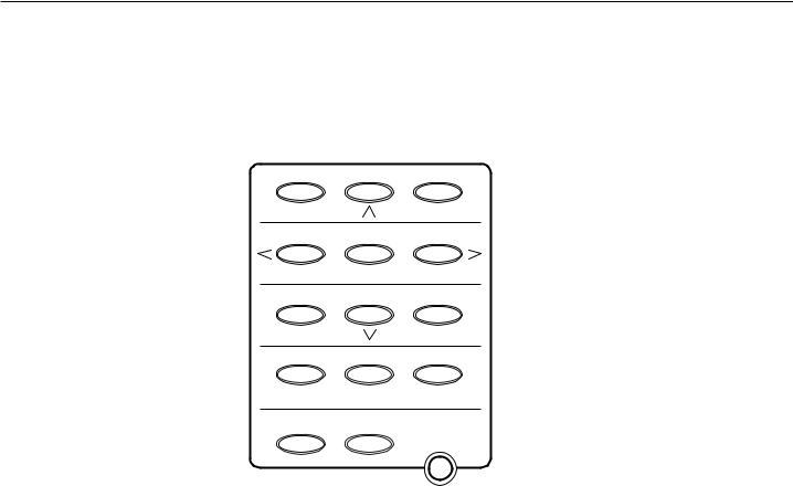
Special Function Buttons
01 |
02 |
03 |
Data Registration |
|
|
04 |
05 |
06 |
Memory Reference Space |
+ |
|
07 |
08 |
09 |
|
Report |
|
10 |
11 |
12 |
Cleaning Clear
Function Set
Resume
Data Registration Button
Accesses the different menus for setting speed dialing, user preferences, sending and receiving options, and many other important settings.
^, V Buttons
Scroll through the settings so you can see other selections in the menus during data registration.
Memory Reference Button
Performs operations with documents currently stored in memory, including printing a list of documents, printing a document, and deleting a document.
Space Button
Enters a space between letters and numbers when registering information.
Figure 1-8 Operation Panel (3)
1-16

MultiPASS C530/C560 Chapter 1: General Description
+ Button
Enters a plus sign (+) when registering your unit telephone/fax number.
<, > Buttons
Move the cursor left or right when registering data.
Report Button
Prints reports containing information registered in the unit and information on transactions.
Cleaning Button
Prints the nozzle check and performs cleaning operations for the BJ cartridge print head and unit rollers.
Clear Button
Clears an entire entry when registering information.
Function Button/Light
Accesses the special function buttons. To use the special function buttons, press this button to turn on its light. To use the one-touch speed dialing buttons, press to turn off its light.
Set Button
Selects a menu setting and registers information during data registration.
Resume Button
Form-feeds paper when printing, and resumes printing after an error is corrected.
Figure 1-9 Operation Panel (4)
1-17
Loading...