


 Loading...
SERVICE
MANUAL
REVISION 0
JAN.1998 FY8-13F2-000
COPYRIGHT © 1998 CANON INC. CANON PC400/420/430,FC200/220 REV.0 JAN.1998 PRINTED IN JAPAN (IMPRIME AU JAPON)

IMPORTANT
THIS DOCUMENTATION IS PUBLISHED BY CANON INC., JAPAN, TO SERVE AS A SOURCE OF REFERENCE FOR WORK IN THE FIELD.
SPECIFICATIONS AND OTHER INFORMATION CONTAINED HEREIN MAY VARY SLIGHTLY FROM ACTUAL MACHINE VALUES OR THOSE FOUND IN ADVERTISING AND OTHER PRINTED MATTER.
ANY QUESTIONS REGARDING INFORMATION CONTAINED HEREIN SHOULD BE DIRECTED TO THE COPIER SERVICE DEPARTMENT OF THE SALES COMPANY.
THIS DOCUMENTATION IS INTENDED FOR ALL SALES AREAS, AND MAY CONTAIN INFORMATION NOT APPLICABLE TO CERTAIN AREAS.
COPYRIGHT © 1998 CANON INC.
Printed in Japan
Imprimé au Japon
Use of this manual should be strictly
supervised to avoid disclosure of
confidential information.
Prepared by
OFFICE IMAGING PRODUCTS TECHNICAL SUPPORT DEPARTMENT 1 OFFICE IMAGING PRODUCTS TECHNICAL SUPPORT DIVISION
CANON INC.
5-1, Hakusan 7-chome, Toride-shi, Ibaraki 302 Japan
COPYRIGHT © 1998 CANON INC. CANON PC400/420/430,FC200/220 REV.0 JAN.1998 PRINTED IN JAPAN (IMPRIME AU JAPON)

INTRODUCTION
This Service Manual provides information needed to service the plain paper copiers FC200/PC400(120V model), FC220/PC420(120V model), and PC430(LGL model) in the field.
The FC200/PC400 differs from the FC220/PC420/PC430 for the following:
Model |
Manual pick-up |
Multifeeder |
AE |
|
|
|
|
FC220/PC420/PC430 |
Not available |
Available |
Available |
|
|
|
|
FC200/PC400 |
Available |
Not available |
Not available |
|
|
|
|
This Service Manual consists of the following chapters:
CHAPTER 1, “General Description,” introduces the copier’s features and specifications, shows how to operate the copier, and explains how copies are made.
CHAPTER 2, “Basic Operation,” provides outlines of the copier's various mechanical workings.
CHAPTER 3, “Exposure System,” discusses the principles of operation used for the copier's lens drive unit and scanner drive unit. It also explains the timing at which these drive units are operated, and shows how they may be disassembled/assembled and adjusted.
CHAPTER 4, “Image Formation System,” discusses the principles of how images are formed. It also explains the timing at which the various units involved in image formation are operated, and shows how they may be disassembled/assembled and adjusted.
CHAPTER 5, “Pick-Up/Feeding System,” explains the principles used from when copy paper is picked up to when a copy is delivered in view of the functions of electrical and mechanical units and in relation to their timing of operation. It also shows how these units may be disassembled/assembled and adjusted.
CHAPTER 6, “Fixing System,” explains the principles used to fuse toner images to transfer media in view of the functions of electrical and mechanical units and in relation to their timing of operation. It also shows how these units may be disassembled/assembled and adjusted.
CHAPTER 7, “Externals/Auxiliary Mechanisms,” shows the copier's external parts, and explains the principles used for the copier's various control mechanisms in view of the functions of electrical and mechanical units and in relation to their timing of operation. It also shows how these units may be disassembled/assembled and adjusted.
CHAPTER 8, “Installation,” introduces requirements for the site of installation, and shows how the copier may be installed using step-by-step instructions.
CHAPTER 9, “Maintenance and Servicing,” provides tables of periodically replaced parts and consumables/durables and scheduled servicing charts.
CHAPTER 10, “Troubleshooting,” provides tables of maintenance/inspection, standards/adjustments, and problem identification (image fault/malfunction).
Appendix contains a general timing chart and general circuit diagrams.
COPYRIGHT © 1998 CANON INC. CANON PC400/420/430,FC200/220 REV.0 JAN.1998 PRINTED IN JAPAN (IMPRIME AU JAPON)
i

The following rules apply throughout this Service Manual:
1.Each chapter contains sections explaining the purpose of specific functions and the relationship between electrical and mechanical systems with reference to the timing of operation.
In the diagrams, |
|
|
|
|
|
|
|
represents the path of mechanical drive |
|
where a sig- |
||
|
|
|
|
|
|
|
|
|||||
|
||||||||||||
nal name accompanies the symbol |
|
, the arrow indicates the direction of the |
||||||||||
|
||||||||||||
electric signal. |
|
|
|
|
|
|
|
|
|
|
|
|
The expression "turn on the power" means flipping on the power switch, closing the front door, and closing the delivery unit door, which results in supplying the machine with power.
2.In the digital circuits, '1' is used to indicate that the voltage level of a given signal is "High," while '0' is used to indicate "Low." (The voltage value, however, differs from circuit to circuit.)
In practically all cases, the internal mechanisms of a microprocessor cannot be checked in the field. Therefore, the operations of the microprocessors used in the machines are not discussed: they are explained in terms of from sensors to the input of the DC controller PCB and from the output of the DC controller PCB to the loads.
Note:
The descriptions in this Service Manual are subject to change without notice for product improvement or other purposes, and major changes will be communicated in the form of Service Information bulletins.
All service persons are expected to have a good understanding of the contents of this Service Manual and all relevant Service Information bulletins and be able to identify and isolate faults in the machine.
ii
COPYRIGHT © 1998 CANON INC. CANON PC400/420/430,FC200/220 REV.0 JAN.1998 PRINTED IN JAPAN (IMPRIME AU JAPON)

CONTENTS
CHAPTER 1 GENERAL DESCRIPTION
|
|
|
|
|
|
|
|
|
I. |
..................................FEATURES |
1-1 |
|
1. |
Time to Replace the Cartridge |
|||
II. |
SPECIFICATIONS ....................... |
1-2 |
|
|
......................................... |
1-11 |
||
III. NAMES OF PARTS ..................... |
1-4 |
|
2. |
Replacing the Cartridge ... |
1-12 |
|||
|
A. |
External View .......................... |
1-4 |
F. |
Changing the Density ........... |
1-14 |
||
|
B. |
Cross Section ......................... |
1-5 |
G. |
Cleaning................................ |
1-14 |
||
IV. OPERATION ................................ |
1-6 |
|
1. |
Copyboard Glass/Copyboard |
||||
|
A. |
Control Panel .......................... |
1-6 |
|
|
Cover ............................... |
1-14 |
|
|
|
1. |
PC420/430/FC220 ............. |
1-6 |
|
2. |
Lens Array ....................... |
1-15 |
|
|
2. |
PC400/FC200 .................... |
1-7 |
|
3. |
Pick-Up Roller.................. |
1-16 |
|
B. |
Making Copies ........................ |
1-8 |
H. When Not Using the Copier for a |
||||
|
C. |
Jam Indicator......................... |
1-11 |
|
Long Time ............................. |
1-16 |
||
|
D. |
Add Paper Indicator .............. |
1-11 |
V. IMAGE FORMATION ................. |
1-17 |
|||
|
E. |
Replacing the Cartridge ........ |
1-11 |
A. Outline..................................... |
1-17 |
|||
|
|
|
|
|
|
|
|
|
|
|
|
|
|
|
|
|
|
CHAPTER 2 BASIC OPERATION
|
|
|
|
|
|
|
....................I. BASIC OPERATION |
2-1 |
1. |
Inputs to DC Controller (1/2) |
|||
A. |
Outline .................................... |
2-1 |
|
........................................... |
2-6 |
|
B. Outline of Electrical Circuit...... |
2-2 |
2. |
Inputs to DC Controller (2/2) |
|||
C. Basic Sequence of Operations |
|
........................................... |
2-7 |
|||
|
(A4, 2 copies).......................... |
2-3 |
F. Outputs from DC Controller .... |
2-8 |
||
D. Main Motor Control Circuit ...... |
2-5 |
1. |
Outputs from DC Controller |
|||
|
1. |
Outline ............................... |
2-5 |
|
(1/2) ................................... |
2-8 |
|
2. |
Operation ........................... |
2-5 |
2. |
Outputs from DC Controller |
|
|
3. |
Overcurrent Sensor ........... |
2-5 |
|
(2/2) ................................... |
2-9 |
E. |
Inputs to DC Controller ........... |
2-6 |
|
|
|
|
|
|
|
|
|
|
|
|
|
|
|
|
|
|
CHAPTER 3 EXPOSURE SYSTEM
I.EXPOSURE/COPYBOARD DRIVE
SYSTEM ...................................... |
3-1 |
|
A. Outline of Exposure System ... |
3-1 |
|
B. Copyboard Drive System........ |
3-1 |
|
1. |
Outline ............................... |
3-1 |
2. |
Controlling the Copyboard |
|
|
Drive .................................. |
3-3 |
3.Mechanism of Copyboard
|
Drive Assembly.................. |
3-4 |
II. Controlling the Scanning Lamp.... |
3-7 |
|
A. |
Outline .................................... |
3-7 |
B. |
Operations .............................. |
3-8 |
1.Turning the Scanning Lamp
ON and OFF ...................... |
3-8 |
2.Controlling the Intensity of the
Scanning Lamp.................. |
3-8 |
C. Controlling the Intensity of the |
|
Scanning Lamp (VR604) ........ |
3-8 |
III. MECHANICAL SYSTEM.............. |
3-9 |
A. Scanning System.................. |
3-10 |
1.Detaching the Scanning Lamp
Unit .................................. |
3-10 |
B.Copyboard Drive Assembly...3-11
1.Detaching the Copyboard
Drive Assembly ................ |
3-11 |
COPYRIGHT © 1998 CANON INC. CANON PC400/420/430,FC200/220 REV.0 JAN.1998 PRINTED IN JAPAN (IMPRIME AU JAPON)
iii

CHAPTER 4 IMAGE FORMATION SYSTEM
|
|
|
|
|
|
|
|
|
..........I. PROCESS DESCRIPTION |
4-1 |
|
|
1. |
.............................Outline |
4-14 |
||
A. |
Outline .................................... |
4-1 |
|
|
2. |
Operations ....................... |
4-14 |
|
B. |
Sequence of Image Formation |
|
|
3. |
Adjusting the AE Mechanism |
|||
|
Operations (A4, 2 copies) ....... |
4-2 |
|
|
|
(VR602, VR603) .............. |
4-15 |
|
C. |
Primary Charging Control Circuit |
II. |
CHARGING, DEVELOPING, AND |
|||||
|
................................................ |
|
4-3 |
|
CLEANING SYSTEMS .............. |
4-17 |
||
|
1. |
Outline ............................... |
4-3 |
|
A. |
Cartridge ............................... |
4-17 |
|
|
2. |
Operations ......................... |
4-4 |
|
|
1. |
Outline ............................. |
4-17 |
D. |
Controlling Developing Bias.... |
4-6 |
III. |
MECHANICAL SYSTEM............ |
4-18 |
|||
|
1. |
Outline ............................... |
4-6 |
|
A. |
Photosensitive Drum............. |
4-19 |
|
|
2. |
Operations ......................... |
4-8 |
|
|
1. |
Cleaning the Drum........... |
4-19 |
E. |
Transfer Charging Control Circuit |
|
B. |
Transfer Charging Roller....... |
4-20 |
|||
|
.............................................. |
|
4-10 |
|
|
1. |
Cleaning the Transfer |
|
|
1. |
Outline ............................. |
4-10 |
|
|
|
Charging Roller................ |
4-20 |
|
2. |
Operations ....................... |
4-11 |
|
|
2. |
Detaching the Transfer |
|
F. |
Document Density Measurement |
|
|
|
Charging Roller................ |
4-20 |
||
|
(AE; PC420/430/FC220)....... |
4-14 |
|
|
|
|
|
|
|
|
|
|
|
|
|
|
|
|
|
|
|
|
|
|
|
|
CHAPTER 5 PICK-UP/FEEDING SYSTEM
|
|
|
|
|
|
I. |
.....................................OUTLINE |
5-1 |
..........D. Pick-Up Stationary Jam |
5-9 |
|
II. |
CONTROLLING THE PICK-UP |
|
1. |
PC420/430/FC220 ............. |
5-9 |
|
ROLLER....................................... |
5-2 |
2. |
PC400/FC200 .................... |
5-9 |
A. |
PC420/430/FC220 .................. |
5-2 |
E. Paper is present at the pick-up or |
|||
B. |
PC400/FC200 ......................... |
5-3 |
|
delivery sensor at time of power- |
||
III. CONTROLLING THE |
|
|
on or when the Copy Start key is |
|||
REGISTRATION ROLLER........... |
5-4 |
|
pressed. .................................. |
5-9 |
||
A. |
Outline .................................... |
5-4 |
V. MECHANICAL SYSTEM............ |
5-10 |
||
B. |
Pick-Up/Feeding Timing Chart |
|
A. |
Pick-Up Roller Assembly....... |
5-11 |
|
|
(A4, 2 copies).......................... |
5-5 |
|
1. Detaching the Pick-Up Roller |
||
IV. CHECKING FOR JAMS............... |
5-6 |
B. |
Registration.........................................Roller Assembly |
5-11 |
||
A. |
Delivery Delay Jam................. |
5-6 |
5-14 |
|||
|
1. |
PC420/430/FC220 ............. |
5-6 |
|
.............................................. |
|
|
2. |
PC400/FC200 .................... |
5-6 |
|
1. Detaching the Registration |
|
B. |
Delivery Stationary Jam.......... |
5-7 |
|
Roller Assembly............... |
5-14 |
|
|
1. |
PC420/430/FC220 ............. |
5-7 |
C. |
Removing the Separation Pad |
|
|
2. |
PC400/FC200 .................... |
5-7 |
|
.............................................. |
5-15 |
C. Pick-Up Delay Jam |
|
|
|
|
||
|
(PC420/430/FC220)................ |
5-8 |
|
|
|
|
|
|
|
|
|
|
|
|
|
|
|
|
|
|
CHAPTER 6 FIXING SYSTEM
I. OUTLINE OF OPERATIONS ....... |
6-1 |
|
A. |
Outline .................................... |
6-1 |
B. |
Controlling the Fixing Heater |
|
|
Temperature............................ |
6-3 |
C. Controlling the Supply Power to
|
the Fixing Heater .................... |
6-3 |
D. |
Protection Mechanisms .......... |
6-5 |
II. MECHANICAL SYSTEM.............. |
6-6 |
|
A. |
Fixing Assembly...................... |
6-7 |
iv
COPYRIGHT © 1998 CANON INC. CANON PC400/420/430,FC200/220 REV.0 JAN.1998 PRINTED IN JAPAN (IMPRIME AU JAPON)

1. |
Construction....................... |
6-7 |
3. |
Removing the Fixing Upper |
|
2. |
Detaching the Fixing |
|
|
Unit |
....................................6-9 |
|
Assembly ........................... |
6-7 |
4. |
Detaching the Pressure Roller |
|
|
|
|
|
......................................... |
6-11 |
|
|
|
|
|
|
|
|
|
|
|
|
CHAPTER 7 EXTERNALS/AUXILIARY MECHANISMS
|
|
|
|
|
|
|
|
........................I. POWER SUPPLY |
7-1 |
|
5. |
Detaching the Bottom Cover |
|||
A. |
Outline .................................... |
7-1 |
|
|
........................................... |
7-8 |
|
B. |
Power Supply PCB ................. |
7-2 |
B. |
Copyboard Assembly.............. |
7-9 |
||
C. Protection Mechanism for Power |
|
1. |
Detaching the Copyboard |
|
|||
|
Supply Circuit.......................... |
7-2 |
|
|
Cover ................................. |
7-9 |
|
II.MECHANICAL SYSTEM ................. |
7-3 |
|
2. |
Detaching the Copyboard .. |
7-9 |
||
A. |
External Covers ...................... |
7-4 |
C. DC Controller/DC Power Supply |
||||
|
1. |
Detaching the Control Panel |
|
PCB....................................... |
7-11 |
||
|
|
Cover ................................. |
7-4 |
|
1. |
Detaching the DC |
|
|
2. |
Detaching the Body Cover |
|
|
|
Controller/DC Power Supply |
|
|
|
........................................... |
7-5 |
|
|
PCB.................................. |
7-11 |
|
3. |
Detaching the Top Cover |
|
|
2. |
Points to Note When Installing |
|
|
|
Assembly ........................... |
7-7 |
|
|
the Delivery Door Switch .7-13 |
|
|
4. |
Detaching the Delivery |
|
D. |
Control Panel PCB................ |
7-14 |
|
|
|
Assembly Cover................. |
7-7 |
|
1. |
Detaching the Control Panel |
|
|
|
|
|
|
|
PCB ................................. |
7-14 |
|
|
|
|
|
|
|
|
|
|
|
|
|
|
|
|
CHAPTER 8 INSTALLATION
|
|
|
...............I. SELECTING THE SITE |
8-1 |
....III. RELOCATING THE MACHINE 8-5 |
II.UNPACKING AND INSTALLATION
.....................................................8-2
CHAPTER 9 MAINTENANCE AND SERVICING
|
|
|
|
|
|
I. |
PERIODICALLY REPLACED PARTS |
B. Storing and Handling Unsealed |
|||
|
..................................................... |
9-1 |
Cartridges ............................... |
9-3 |
|
II. |
DURABLES.................................. |
9-1 |
1. |
Storing Unsealed Cartridges |
|
III. PERIODICAL SERVICING .......... |
9-1 |
|
........................................... |
9-3 |
|
IV. NOTES ABOUT CARTRIDGE ..... |
9-2 |
2. |
Handling the Cartridge....... |
9-3 |
|
|
A. Storing Sealed Cartridges....... |
9-2 |
|
|
|
|
|
|
|
|
|
|
|
|
|
|
|
CHAPTER 10 TROUBLESHOOTING
|
|
|
|
|
|
|
I. |
MAINTENANCE AND INSPECTION |
........................ADJUSTMENTS |
10-5 |
|||
|
................................................... |
|
10-3 |
A. Mechanical............................ |
10-5 |
|
|
A. |
Image Adjustment Basic |
|
1. |
Image Leading Edge Non- |
|
|
|
Procedure ............................. |
10-3 |
|
Image Width (position of white |
|
|
B. |
Points to Note ....................... |
10-4 |
|
paint on back of glass)..... |
10-5 |
II. |
STANDARDS AND |
|
2. |
Image Leading Edge Margin |
||
COPYRIGHT © 1998 CANON INC. CANON PC400/420/430,FC200/220 REV.0 JAN.1998 PRINTED IN JAPAN (IMPRIME AU JAPON)
v

|
|
(point of detection for |
|
|
|
(cross feed direction). .... |
10-20 |
|
|
registration)...................... |
10-5 |
|
13. |
The back of the copy is soiled. |
|
B. |
Electrical ............................... |
10-6 |
|
|
....................................... |
10-20 |
|
|
1. |
Adjusting the Intensity |
|
|
14. |
The copy has faulty fixing. |
|
|
|
(VR604) ........................... |
10-6 |
|
|
....................................... |
10-21 |
|
2. |
Adjusting the AE Mechanism |
|
15. |
The copy has faulty leading |
||
|
|
(VR602, VR603) .............. |
10-8 |
|
|
edge registration (blank area |
|
III. IMAGE TROUBLESHOOTING 10-11 |
|
|
much too wide). ............. |
10-21 |
|||
A. |
Making Initial Checks .......... |
10-11 |
|
16. |
The copy has faulty leading |
||
|
1. |
Site Environment............ |
10-11 |
|
|
edge registration (blank area |
|
|
2. |
Checking the Documents |
|
|
too wide). ....................... |
10-21 |
|
|
|
....................................... |
10-11 |
|
17. |
The copy has faulty leading |
|
|
3. |
Checking the Copyboard |
|
|
edge registration (no blank |
||
|
|
Cover and Copyboard Glass |
|
|
area). ............................. |
10-21 |
|
|
|
for Dirt and Scratches .... |
10-12 |
|
18. |
The copy has a blurred image. |
|
|
4. |
Checking the Lens Array for |
|
|
....................................... |
10-22 |
|
|
|
Dirt ................................. |
10-12 |
|
19. |
The copy is foggy (cross feed |
|
|
5. |
Checking the Transfer |
|
|
|
direction). ....................... |
10-22 |
|
|
Charging Roller.............. |
10-12 |
|
20. |
The copy has poor sharpness |
|
|
6. |
Checking the Feeding |
|
|
|
(focus)............................ |
10-22 |
|
|
Assembly ....................... |
10-12 |
|
21. |
The copy is blank........... |
10-23 |
|
7. |
Checking the Copy Paper |
|
22. |
The copy is solid black... |
10-23 |
|
|
|
....................................... |
10-12 |
IV. TROUBLESHOOTING |
|
||
|
8. |
Checking the Durables .. |
10-12 |
MALFUNCTIONS..................... |
10-24 |
||
|
9. |
Others ............................ |
10-14 |
A. |
Troubleshooting Malfunctions |
||
B. Samples of Image Faults .... |
10-16 |
|
1............................................. |
(self diagnosis; |
10-24 |
||
C. |
Troubleshooting by Image Fault |
|
|
||||
|
............................................ |
|
10-17 |
|
|
PC400/FC200)............... |
10-24 |
|
1. |
The copy is too light (halftone |
|
2. |
E0 .................................. |
10-24 |
|
|
|
areas only). .................... |
10-17 |
|
3. |
E2 .................................. |
10-25 |
|
2. |
The copy is too light (dark |
|
4. |
E6 .................................. |
10-25 |
|
|
|
areas as well)................. |
10-17 |
|
5. |
E9 .................................. |
10-26 |
|
3. |
The copy is too light |
|
|
6. |
AC power is absent........ |
10-26 |
|
|
(extremely light overall).. |
10-17 |
|
7. |
Pick-up fails. .................. |
10-27 |
|
4. |
The copy has uneven density |
|
8. |
The scanning lamp fails to go |
||
|
|
(darker at front). ............. |
10-18 |
|
|
ON. ................................ |
10-27 |
|
5. |
The copy has uneven density |
|
9. |
The main motor fails to rotate. |
||
|
|
(lighter at front). ............. |
10-18 |
|
|
....................................... |
10-28 |
|
6. |
The copy is foggy (overall). |
|
10. |
The copyboard fails to move. |
||
|
|
....................................... |
10-18 |
|
|
....................................... |
10-28 |
|
7. |
The copy is foggy (paper feed |
|
11. |
(paper feeding normally) |
||
|
|
direction). ....................... |
10-19 |
|
|
....................................... |
10-29 |
|
8. |
The copy has dark lines |
|
|
12. |
(at time of jam) .......... |
10-29 |
|
|
(paper feed direction, |
10-19 |
|
13. |
The fixing heater fails to |
|
|
|
relatively narrow). .......... |
|
|
operate |
10-29 |
|
|
9. |
The copy has dark lines |
|
|
|
||
|
|
V. TROUBLESHOOTING PAPER |
|
||||
|
|
(paper feed direction, thin). |
FEED PROBLEMS .................. |
10-30 |
|||
|
|
....................................... |
10-19 |
A. |
Copy Paper Jams ............... |
10-30 |
|
|
10. |
The copy has white spots |
|
1. |
Pick-Up Assembly.......... |
10-31 |
|
|
|
(paper feed direction)..... |
10-19 |
|
2. |
Separation/Feeding Assembly |
|
|
11. |
The copy has white lines |
|
|
....................................... |
10-31 |
|
|
|
(paper feed direction)..... |
10-19 |
|
3. |
Fixing/Delivery Assembly |
|
|
12. |
The copy has white spots |
|
|
....................................... |
10-32 |
|
vi
COPYRIGHT © 1998 CANON INC. CANON PC400/420/430,FC200/220 REV.0 JAN.1998 PRINTED IN JAPAN (IMPRIME AU JAPON)

B. |
Feeding Faults .................... |
10-33 |
............................................ |
|
10-36 |
|
|
1. |
Double Feeding ............. |
10-33 |
D. Printed Circuit Board (PCB)10-37 |
||
|
2. |
Wrinkles ......................... |
10-33 |
E. Variable Resistors (VR) and |
|
|
VI. FUNCTIONS AND ARRANGEMENT |
Check Pins by PCB ............ |
10-38 |
||||
OF ELECTRICAL PARTS ........ |
10-34 |
1. |
DC Controller/DC Power |
|
||
A. |
Sensors and Solenoids....... |
10-34 |
|
Supply PCB ................... |
10-38 |
|
B. |
Switches ............................. |
10-35 |
2. |
Control Panel PCB......... |
10-39 |
|
C. |
Lamp, Heater, Motor, and Others |
VII. SELF DIAGNOSIS ................... |
10-40 |
|||
|
|
|
|
|
|
|
|
|
|
|
|
|
|
APPENDIX
A. GENERAL TIMING CHART ......... |
A-1 |
|
B. SIGNALS/ABBREVIATIONS LISTA-3 |
||
1. |
Signals.................................... |
A-3 |
2. |
Abbreviations.......................... |
A-4 |
C. GENERAL CIRCUIT DIAGRAM... |
A-5 |
D. SPECIAL TOOLS TABLE ............. |
A-7 |
E. SOLVENTS/OILS TABLE ............. |
A-8 |
COPYRIGHT © 1998 CANON INC. CANON PC400/420/430,FC200/220 REV.0 JAN.1998 PRINTED IN JAPAN (IMPRIME AU JAPON)
vii
viii
COPYRIGHT © 1998 CANON INC. CANON PC400/420/430,FC200/220 REV.0 JAN.1998 PRINTED IN JAPAN (IMPRIME AU JAPON)
CHAPTER 1
GENERAL DESCRIPTION
This chapter outlines the machine's specifications and how it may be operated.
I. |
FEATURES .................................. |
1-1 |
|
II. |
SPECIFICATIONS ....................... |
1-2 |
|
III. NAMES OF PARTS ..................... |
1-4 |
||
|
A. |
External View .......................... |
1-4 |
|
B. |
Cross Section ......................... |
1-5 |
IV. OPERATION ................................ |
1-6 |
||
|
A. |
Control Panel .......................... |
1-6 |
|
B. |
Making Copies ........................ |
1-8 |
|
C. |
Jam Indicator......................... |
1-11 |
D. |
Add Paper Indicator .............. |
1-11 |
E. |
Replacing the Cartridge ........ |
1-11 |
F. |
Changing the Density ........... |
1-14 |
G. |
Cleaning................................ |
1-14 |
H. |
When Not Using the Copier for a |
|
|
Long Time ............................. |
1-16 |
V. IMAGE FORMATION ................. |
1-17 |
|
A. Outline..................................... |
1-17 |
|
COPYRIGHT © 1998 CANON INC. CANON PC400/420/430,FC200/220 REV.0 JAN.1998 PRINTED IN JAPAN (IMPRIME AU JAPON) |
1 |

CHAPTER 1 GENERAL DESCRIPTION
Blank Page
COPYRIGHT © 1998 CANON INC. CANON PC400/420/430,FC200/220 REV.0 JAN.1998 PRINTED IN JAPAN (IMPRIME AU JAPON)

CHAPTER 1 GENERAL DESCRIPTION
I. FEATURES
1.Direct charging.
The charging roller directly charges paper, significantly reducing ozone emission.
2.Auto power-off.
The copier shuts off automatically when left alone for about 5 minutes after the last
copy operation.
3.Quick start.
The copier’s wait time is 0 second, always ready for quick copying work.
4.Cartridge type.
The core of the copier (photosensitive drum, toner case, charging roller, developing
assembly, and cleaning assembly) is integrated into a single cartridge. The user need no more than replace the cartridge and perform simple cleaning to maintain the copier in top condition.
5.Variety of copy effects.
In addition to black toner, the user has a choice of several colors. Taking advantage
of overlay copying, various copy effects may be obtained through mere replacement of the cartridge.
6.Compact and light.
The copier is compact and light, providing good portability. It can easily substitute
as a personal copier.
7.Multifeeding (PC420/430/FC220).
A stack of copy paper may be placed on the pick-up tray. A press on the Copy Start
key is all it takes to generate multiple copies.
COPYRIGHT © 1998 CANON INC. CANON PC400/420/430,FC200/220 REV.0 JAN.1998 PRINTED IN JAPAN (IMPRIME AU JAPON) |
1-1 |

CHAPTER 1 GENERAL DESCRIPTION
II. SPECIFICATIONS
|
Item |
PC400/FC200 |
PC420/430/FC220 |
||
|
|
|
|
|
|
|
Body |
Portable (w/ grips) |
|
||
|
|
|
|
|
|
Type |
Copyboard |
Moving |
|
||
|
|
|
|
|
|
Light source |
Tungsten lamp of fuse type |
|
|||
|
|
||||
|
|
|
|
|
|
|
Lens |
Lens array |
|
||
|
|
|
|
|
|
|
Photosensitive medium |
OPC (24 dia.) |
|
||
|
|
|
|
|
|
|
Copying |
Indirect electrostatic |
|
||
|
|
|
|
|
|
|
Charging |
Roller (direct charging) |
|
||
|
|
|
|
|
|
|
Exposure |
Slit (moving copyboard) |
|
||
|
|
|
|
|
|
System |
Copy density adjustment |
Manual |
Automatic (AE) or Manual |
||
|
|
|
|
|
|
Development |
Dry |
|
|||
|
|
||||
|
|
|
|
|
|
|
Pick-up |
Manual tray |
Multifeeder |
||
|
|
|
|
|
|
|
Separation |
Curvature + Static eliminator |
|
||
|
|
|
|
|
|
|
Cleaning |
Blade |
|
||
|
|
|
|
|
|
|
Fixing |
Plane heater |
|
||
|
|
|
|
|
|
|
Document type |
Sheet, Book, 3-D object (2 kg/4.4 lb max.) |
|||
|
|
|
|
|
|
|
Maximum document size |
LTR/A4; LGL* |
|
||
|
|
|
|
|
|
|
Reproduction ratio |
1:1 (±1.2%) |
|
|
|
|
|
|
|
|
|
|
Wait time |
0 sec (approx.; at 20°C/68°F) |
|
||
|
|
|
|
|
|
|
First copy |
22 sec (LTR) |
|
||
|
|
|
|
|
|
|
Continuous copying |
Not available |
1 to 9 copies or F |
||
|
|
|
|
|
|
|
Copying speed |
4 copies/min (approx.; A4R/LTR-R |
4 copies/min (A4R/LTR-R or |
||
|
|
or smaller) |
smaller) |
||
|
|
|
|
|
3 copies/min (LGL) |
Performance |
|
|
|
|
|
Copy size |
A4/LTR; LGL* max.; postcard min. |
|
|||
|
|
||||
|
|
|
|
|
|
|
Copy paper type |
52 to 128 g/m2, Tracing paper, Colored paper, OHP film, Postcard |
|||
|
|
(vertical), Labels, Wrapping paper (63 g/m2) |
|||
|
Two-sided copying |
• Same edge orientation. |
• Paper of 64 to 128 g/m2. |
||
|
|
• Copying on each side no more |
|
||
|
|
than twice. |
|
||
|
|
|
|
|
|
|
Overlay copying |
• Paper of 64 to 128 g/m2. |
• Copying on each side no more |
||
|
|
|
|
|
than three times. |
|
|
|
|
|
|
|
Multifeeder tray |
|
|
|
5 mm deep (about 50 sheets of |
|
|
|
|
|
A4, 80 g/m2) |
|
|
|
|
|
|
|
Copy tray |
|
|
|
9 copies (approx.; A4/LTR, 80 g/m2) |
|
|
|
|
||
|
Non-image width |
2 mm (leading edge) |
|
||
|
|
A4: 0 mm (left/right) |
|
||
|
|
LTR/LGL: 2 mm (left/right) |
|
||
|
|
|
|
|
|
|
Auto power-off |
Available (5 min, approx.) |
|
||
|
|
|
|
|
|
|
*PC430 only. |
|
|
|
|
1-2 |
COPYRIGHT © 1998 CANON INC. CANON PC400/420/430,FC200/220 REV.0 JAN.1998 PRINTED IN JAPAN (IMPRIME AU JAPON) |

CHAPTER 1 GENERAL DESCRIPTION
Others
|
|
Item |
PC400/FC200 |
PC420/430/FC220 |
|||
Operating |
|
Temperature |
7.5° to 32.5°C/45.5° to 90.5°F |
|
|
||
|
|
|
|||||
|
|
|
|
|
|
|
|
|
Humidity |
5% to 85% |
|
|
|||
environment |
|
|
|
||||
|
Atmospheric pressure |
810.6 hPa to 1013.3 hPa (0.8 to 1 atm) |
|||||
|
|
||||||
|
|
|
|
|
|
|
|
|
|
|
Serial numbers |
Serial numbers |
|||
|
|
|
|
|
|
|
|
|
|
120V, 60Hz |
ZTG (PC400:WHITE) |
NVD |
|||
|
|
|
ZTH (PC400:GRAY) |
|
|||
|
|
|
|
|
|
(FC220:WHITE) |
|
Power |
|
|
|
|
|
ZTJ |
|
|
|
|
|
|
|
||
supply |
|
|
|
|
|
||
|
|
|
|
|
(PC420:WHITE) |
||
|
|
|
|
|
|
||
|
|
|
|
|
|||
|
|
230V, 50Hz |
RTL/PTQ |
RTM/PTR |
|||
|
|
|
|
(FC220:WHITE) |
|||
|
|
|
(FC200:WHITE) |
PTS (FC220:WHITE) |
|||
|
|
|
UTP/UTQ |
PTT (FC220:WHITE) |
|||
|
|
|
|
|
|
|
|
Power |
|
Maximum |
0.7 kW or less |
|
|
||
|
|
|
|
|
|
|
|
|
Standby |
0.1 W (approx.; 5 min; reference only) |
|||||
consumption |
|
||||||
|
Continuous |
0.2 kWh (reference only) |
|
|
|||
|
|
|
|
||||
|
|
|
|
|
|
|
|
Noise |
|
Copying |
71 dB |
|
Sound power level |
||
|
|
|
|
|
|
by ISO |
|
|
Standby |
|
|
|
|
||
|
|
|
|
|
|
||
|
|
|
|
|
|
|
|
|
|
|
|
|
|
|
|
Ozone |
|
|
0.01 ppm or less (average over 8 hr) |
||||
|
|
|
|
|
|
|
|
|
|
Width |
14.1 in./359 mm |
|
|
||
|
|
|
|
|
|
|
|
Dimensions |
|
Depth |
15.7 in./402 mm |
|
|
||
|
|
|
|
|
|
|
|
|
|
Height |
4.1 in./108 mm |
|
|
||
|
|
|
|
|
|
|
|
Weight (including cartridge) |
16.6 lb/7.4 kg (approx.) |
|
|
||||
|
|
|
|
|
|
|
|
Consumables |
|
Copy paper |
Keep wrapped to protect against humidity. |
||||
|
|
|
|
|
|
|
|
|
Cartridge |
See CHAPTER 9. |
|
|
|||
|
|
|
|
||||
|
|
|
|
|
|
|
|
Specifications subject to change without notice.
COPYRIGHT © 1998 CANON INC. CANON PC400/420/430,FC200/220 REV.0 JAN.1998 PRINTED IN JAPAN (IMPRIME AU JAPON) |
1-3 |
CHAPTER 1 GENERAL DESCRIPTION
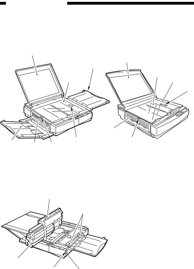
III. NAMES OF PARTS
A. External View
(PC420/430/FC220) |
(PC400/FC200) |
|
|
|
|
|
|
|
|
|
|
|
|
|
|
|
|
|
|
|
|
|
|
|
||
|
q Copyboard cover |
t Delivery assembly cover |
|
|
w Copyboard glass |
open/close button |
|
|
e Pick-up tray |
y Delivery assembly cover |
|
|
r Open/Close button |
u Copy tray |
|
Figure 1-301A

q Upper cover w Pick-up guide
e Density correction switch r Power switch
t Cartridge
Figure 1-302A
1-4 |
COPYRIGHT © 1998 CANON INC. CANON PC400/420/430,FC200/220 REV.0 JAN.1998 PRINTED IN JAPAN (IMPRIME AU JAPON) |

CHAPTER 1 GENERAL DESCRIPTION
B. Cross Section
(PC420/430/FC220)
1 |
2 |
3 |
4 |
5 |
6 |
7 |
8 |
9 |
10 |
17 |
16 |
15 14 |
13 |
12 |
11 |
(PC400/FC200)
12 11 8
q Copyboard cover w Copyboard glass e Cleaning assembly
r Primary charging roller t Scanning lamp
y Lens array
u Developing cylinder i Registration roller o Pick-up roller
9
!0Pick-up tray
!1Transfer charging roller
!2Photosensitive drum !3Fixing assembly !4Delivery roller !5Delivery tray
!6Heat exhaust fan
!7Delivery assembly cover open/close button
Figure 1-301B
COPYRIGHT © 1998 CANON INC. CANON PC400/420/430,FC200/220 REV.0 JAN.1998 PRINTED IN JAPAN (IMPRIME AU JAPON) |
1-5 |
CHAPTER 1 GENERAL DESCRIPTION
IV. OPERATION
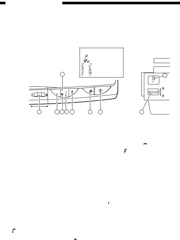
A. Control Panel
1. PC420/430/FC220
|
Error indications |
|
|
|
|
: Check jam/Supply paper |
|
|
|
: Jam |
|
|
and |
: Check error |
|
|
and |
: Check error |
|
3 |
and |
: Check error |
9 |
|
|
|
|
|
|
|
ON OFF |
|
|
|
darker |
|
|
AE |
C |
6 |
5 |
A |
|
4 |
lighter |
||
|
|
|
lighter darker
1 |
2 |
4 |
5 |
6 |
7 |
8 |
10 |
Figure 1-401A
q Density Control Dial
wAE key
•Press it to select/deselect AE (automatic exposure) mode.
eAE Indicator
•‘A’ goes ON when AE mode is selected.
•‘A’ goes OFF when AE mode is deselected.
rJam Indicator
•Flashes when paper jams inside the copier.
tCopy Count Indicator
•Displays the number of copies entered by pressing the Copy Count Set key.
•The count decreases for each copy made; the initial number is displayed after the last copy has been made.
•‘
 ’ is displayed to indicate pick-up failure or absence of paper; ‘
 ’ is displayed in response to an error found by self diagnosis.
yCopy Count Set Key
•Each press on the key increases the copy count (up to 9).
•A press while ‘
 ’ is displayed causes ‘
 ’ to appear, indicating all sheets on the pick-up tray will be
used for continuous copying.
uClear/Stop Key
•During continuous copying, the key serves as a Copy Stop key; the operation stops after finishing the ongoing copy.
•During standby, the key serves as a Clear key, setting the copy count to
‘ ’.
’.
i Copy Start Key
o Power Switch
!0Density Correction Switch
•Switches copy density among three settings (top for darker, bottom for lighter).
•The density is switched by varying the developing bias.
1-6 |
COPYRIGHT © 1998 CANON INC. CANON PC400/420/430,FC200/220 REV.0 JAN.1998 PRINTED IN JAPAN (IMPRIME AU JAPON) |
CHAPTER 1 GENERAL DESCRIPTION
2. PC400/FC200
2
ON OFF |
5
lighter |
darker |
|
|
1 |
3 |
4 |
|
|
Figure 1-402A |
(right view) |
|
q Density Control Lever
w Density Indicator
eJam Indicator
•Flashes when paper jams inside the copier.
•Goes and remains ON when an error (self diagnosis) occurs in the copier.
rMain Indicator
•Remains ON when copying is ready.
t Power Switch
COPYRIGHT © 1998 CANON INC. CANON PC400/420/430,FC200/220 REV.0 JAN.1998 PRINTED IN JAPAN (IMPRIME AU JAPON) |
1-7 |
CHAPTER 1 GENERAL DESCRIPTION
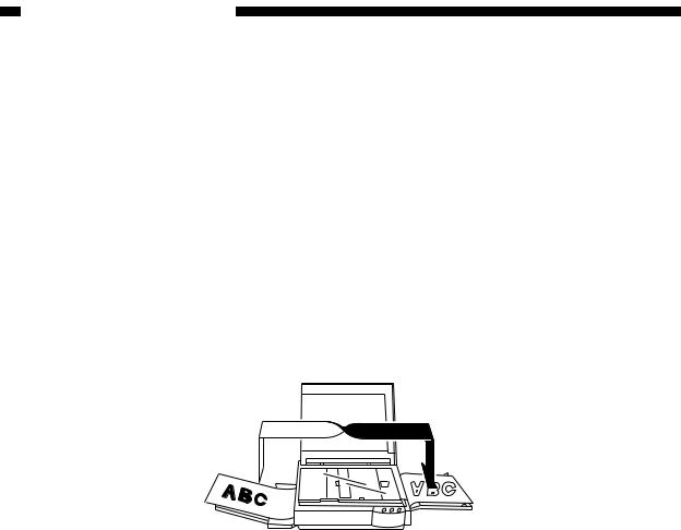
B. Making Copies
1)Switch the copier ON.
•If necessary, wait until the intensity of the scanning lamp reaches the specified value.
•The wait time is about 0 second.
•The copier will shut itself off in about 5 minutes if left alone without key operation.
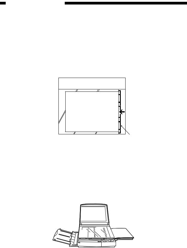
2)Lift the copyboard cover, and place a document face down, along the size index.
•Place the document so that its center is at  on the size index (Figure 1-401B); then, close the copyboard cover.
Document
Size index
Figure 1-401B
3)Adjust the copy density to suit the document.
4)Slide the pick-up guide to suit the size of copy paper.
5)Set copy paper on the pick-up tray.
PC420/430/FC220
Place a stack of copy paper of a size suited to the document on the pick-up tray; make sure the edges of the sheets are flush.
• The stack may be 5 mm (about 50 sheets of plain paper).
Figure 1-402B
6) Set the copy count.
PC420/430/FC220
Set the number of copies to make (1 to 9 or F) using the + key, and check the Copy
Count indicator.
1-8 |
COPYRIGHT © 1998 CANON INC. CANON PC400/420/430,FC200/220 REV.0 JAN.1998 PRINTED IN JAPAN (IMPRIME AU JAPON) |
CHAPTER 1 GENERAL DESCRIPTION
7)Press the Copy Start key.
PC420/430/FC220
•To stop continuous copying, press the Clear/Stop key; the copier finishes the ongoing copy and stops. The copy count displays the initial count.
Copying on OHP Film
•Set one sheet of film on the pick-up tray for each copy.
•Depending on the environment of the site, a press on the Copy Start key may not pull the film inside the copier; if this is the case, perform the following:
1)Place copy paper under the film; stagger the sheet and film so that the leading edge of the film is about 1 cm behind that of the paper.
1cm
Figure 1-403B
2)Hold the trailing edge of the copy paper, and set the sheet and film on the pick-up tray.
3)While holding the trailing edge of the copy paper, press the Copy Start key.
Remove the paper when the film begins to move into the copier; the paper will no longer serve its purpose.
Figure 1-404B |
Note:
Take away each OHP film delivered to the copy tray.
COPYRIGHT © 1998 CANON INC. CANON PC400/420/430,FC200/220 REV.0 JAN.1998 PRINTED IN JAPAN (IMPRIME AU JAPON) |
1-9 |
CHAPTER 1 GENERAL DESCRIPTION
Manual Feeding
PC400/FC200
1)Set a document on the copyboard.
2)Adjust the Density Control lever to suit the document.
3)Slide the pick-up guide to suit the size of copy paper.
4)Insert copy paper along the pick-up guide.
•The copier starts copying operation automatically as soon as it detects paper.
•To continue copying, insert the next paper when the copyboard starts to return.
Making Two-Sided Copies
1)Turn over the copy while maintaining its feeding direction.
•Make sure that the paper is not moist or curled.
•Use paper of 64 to 128 g/m2 when making two-sided copies.
•Do not process each side more than twice.
Figure 1-405B
Making Overlay Copies
You can make twoor three-colored copies by replacing the cartridge.
•Use paper of 64 to 128 g/m2 when making overlay copies.
•Do not process each side more than three times.
1-10 |
COPYRIGHT © 1998 CANON INC. CANON PC400/420/430,FC200/220 REV.0 JAN.1998 PRINTED IN JAPAN (IMPRIME AU JAPON) |

CHAPTER 1 GENERAL DESCRIPTION
C. Jam Indicator
The Jam indicator starts to flash when paper jams inside the copier.
•Take care not to tear the paper when removing it; otherwise, be sure to remove all pieces of paper.
1)Move the copyboard to the left until it stops.
2)Press the open/close button, and open the top cover.
3)Remove the jam.
•If the jam is in the pick-up or fixing assembly, hold the edge of the paper with both hands, and pull it out slowly through the opening of the top cover.
•If the jam is in the delivery assembly, press the delivery assembly open/close button to open the delivery cover; then, detach the paper from the delivery cover, and pull it slowly in the direction of delivery.
4)Close the top cover and delivery cover; then, move the copyboard to the center.
•To resume copying, switch the copier ON, set the desired copy count, and set the copy density.
D. Add Paper Indicator
PC420/430/FC220
‘ ’ flashes if you try to make a copy when the pick-up tray has run out of paper.
1)Check the pick-up tray for copy paper.
2)If no paper is on the tray, place paper.
If a stack of paper is on the tray, remove it first, then place it back after putting its edges flush.
3)Press the Copy Start key.
• ‘

 ’ goes OFF, and the remaining number of copies are made.
E. Replacing the Cartridge
1.Time to Replace the Cartridge
When the cartridge is running out of toner, copies tend to show white lines or vertical
white spots (Figure 1-401E).
Figure 1-401E
COPYRIGHT © 1998 CANON INC. CANON PC400/420/430,FC200/220 REV.0 JAN.1998 PRINTED IN JAPAN (IMPRIME AU JAPON) |
1-11 |

CHAPTER 1 GENERAL DESCRIPTION
If white lines or spots appear on copies, replace the cartridge as follows:
1)Remove the cartridge from the copier, and rotate it several times as shown in Figure 1-402E.
Figure 1-402E
2) Set the cartridge back in the copier, and make a copy.
a.If the output returns to normal,
•The cartridge may be used further; advise the user, however, to obtain a spare cartridge.
b.If the output fails to return to normal,
•Replace the cartridge as described below.
2. Replacing the Cartridge
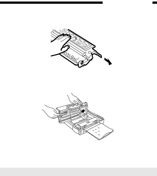
1)Move the copyboard to the left until it stops; then, press the open/close button to open the top cover.
2)Slide the cartridge out of the copier.
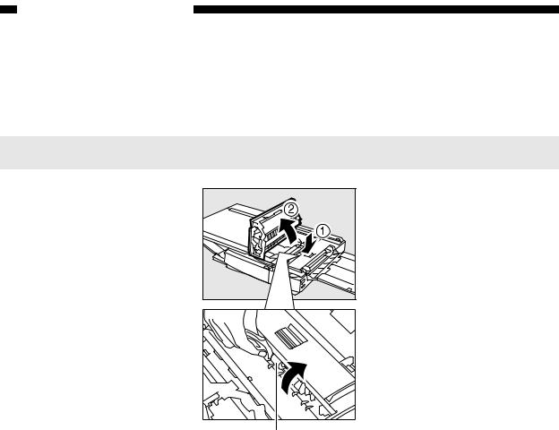
3)Hold the cartridge with the Warning label facing up, and rotate it about 90 degrees in both directions.
Figure 1-403E
1-12 |
COPYRIGHT © 1998 CANON INC. CANON PC400/420/430,FC200/220 REV.0 JAN.1998 PRINTED IN JAPAN (IMPRIME AU JAPON) |
CHAPTER 1 GENERAL DESCRIPTION
4)Detach the tip of the seal attached to the cartridge, and pull it straight out to the front; about 50 cm.
Figure 1-404E
5)Hold the cartridge with its Warning label facing the left, and insert it in the copier with care until it butts against the rear.
Figure 1-405E
6) Close the top cover, and return the copyboard to the center.
Note:
You can replace the black toner cartridge with any color cartridge the same way.
COPYRIGHT © 1998 CANON INC. CANON PC400/420/430,FC200/220 REV.0 JAN.1998 PRINTED IN JAPAN (IMPRIME AU JAPON) |
1-13 |

CHAPTER 1 GENERAL DESCRIPTION
F. Changing the Density
PC420/430/FC220
You have a choice of three settings for automatic density adjustment mode (AE); switch the density if the copy is too dark or too light.
Density Correction Switch
Auto density |
correction |
Figure 1-401F |
Note:
You can also switch the density among three settings in manual density adjustment mode.
G. Cleaning
Advise the user to clean the following if the copies are soiled.
1.Copyboard Glass/Copyboard Cover
Wipe the part with a moist cloth; then, dry wipe it.
If dirt cannot be removed, wipe the part using mild detergent; then, dry wipe it.
1-14 |
COPYRIGHT © 1998 CANON INC. CANON PC400/420/430,FC200/220 REV.0 JAN.1998 PRINTED IN JAPAN (IMPRIME AU JAPON) |

CHAPTER 1 GENERAL DESCRIPTION
2. Lens Array
1)Move the copyboard to the left until it stops.
2)Put a cotton wad in the lens array groove, and move it back and forth lightly.
Fiber lens (face side)
Figure 1-401G |
3)Open the upper cover, and remove the cartridge.
4)Put a flat-tipped cotton wad in the lens array (rear) groove, and move it back and forth.
Figure 1-402G |
COPYRIGHT © 1998 CANON INC. CANON PC400/420/430,FC200/220 REV.0 JAN.1998 PRINTED IN JAPAN (IMPRIME AU JAPON) |
1-15 |
CHAPTER 1 GENERAL DESCRIPTION
3. Pick-Up Roller
1)Open the top cover.
2)Dry wipe the pick-up roller while rotating it in pick-up direction with a cloth.
Note:
Do not make copies until the pick-up roller has completely dried.
Pick-up roller
Figure 1-403G
H. When Not Using the Copier for a Long Time
Advise the user to perform the following if she/he does not have any plan to use the copier for a long time.
1)Disconnect the power plug.
2)Place the copier in a dust-free, sunlight-free place.
1-16 |
COPYRIGHT © 1998 CANON INC. CANON PC400/420/430,FC200/220 REV.0 JAN.1998 PRINTED IN JAPAN (IMPRIME AU JAPON) |
CHAPTER 1 GENERAL DESCRIPTION
V. IMAGE FORMATION
A. Outline
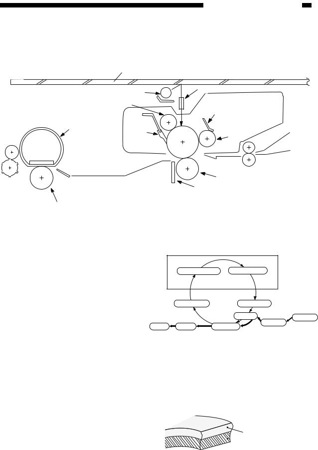
|
Copyboard glass |
|
|
|
|
Scanning lamp |
|
|
Lens array |
|
|
|
|
|
Primary charging roller |
|
Developing blade |
||
|
|
|
||
Fixing film |
Cleaning |
Photo- |
|
Developing |
|
blade |
|
cylinder |
|
|
sensitive drum |
|||
|
|
|
||
Transfer charging roller
Static eliminator
Pressure roller
Figure 1-501A
The copier is an indirect photorepro graphic system constructed as shown in Figure 1-501A.
The image formation process con sists of seven steps as discussed below.
Latent static Image Formation
1. Primary charging |
2. Image exposure |
Step 1 : Primary charging (negative) Step 2 : Image exposure
Step 3 : Development (AC and DC bias) Step 4 : Transfer (negative)
Step 5 : Separation
Step 6 : Fixing
Step 7 : Drum cleaning
|
7. Drum cleaning |
3. Development |
|
|
|
4. Transfer |
Multifeeder |
|
|
Registration |
|
|
6. Fixing |
|
|
Delivery |
5. Separation |
|
 : Flow of copy paper
  : Rotation of drum
Figure 1-502A
The photosensitive drum has a layer construction: the photoconductive layer on the outside and the conductive alu minum base, inside.
Photoconductive layer
 Aluminum base
Figure 1-503A
COPYRIGHT © 1998 CANON INC. CANON PC400/420/430,FC200/220 REV.0 JAN.1998 PRINTED IN JAPAN (IMPRIME AU JAPON) |
1-17 |

CHAPTER 1 GENERAL DESCRIPTION
1-18 |
COPYRIGHT © 1998 CANON INC. CANON PC400/420/430,FC200/220 REV.0 JAN.1998 PRINTED IN JAPAN (IMPRIME AU JAPON) |
Loading...