


 Loading...
FINISHER-C1/ SADDLE FINISHER-C2
SERVICE
MANUAL
REVISION 0
DEC. 1998 |
FY8-13F6-000 |
COPYRIGHT © 1998 CANON INC. |
FINISHER-C1/SADDLE FINISHER-C2 REV. 0 DEC. 1998 PRINTED IN JAPAN (IMPRIME AU JAPON) |

IMPORTANT
THE INFORMATION CONTAINED HEREIN PUBLISHED BY CANON, INC., JAPAN. SPECIFICATIONS AND OTHER INFORMATION CONTAINED WHEREIN MAY SLIGHTLY FROM ACTUAL MACHINE VALUES OR THOSE FOUND IN ADVERTISING AND OTHER PRINTED MATTER.
ANY QUESTIONS REGARDING INFORMATION CONTAINED HEREIN SHOULD BE DIRECTED TO THE COPIER SERVICE DEPARTMENT OF THE COMPANY.
COPYRIGHT © 1998 CANON INC.
Printed in Japan
ImprimÈ au Japon
Use of this manual should be strictly supervised to avoid disclosure of confidential information.
Prepared by
OFFICE IMAGING PRODUCTS TECHNICAL SUPPORT DEPARTMENT 1 OFFICE IMAGING PRODUCTS TECHNICAL SUPPORT DIVISION
CANON INC.
5-1, Hakusan 7-chome, Toride-shi Ibaraki, 302-8501 Japan
COPYRIGHT © 1998 CANON INC. |
FINISHER-C1/SADDLE FINISHER-C2 REV. 0 DEC. 1998 PRINTED IN JAPAN (IMPRIME AU JAPON) |
Preparedby
Office Imaging Products Technical Support Dept. 1
Office Imaging Produce QualityAssurance Center.
CANONINC
Printed in Japan
REVISION0(DEC.1998)(18756)
5-1, Hakusan 7-chome, Toride-shi Ibaraki, 302-8501 Japan

INTRODUCTION
This Service Manual contains basic data and figures for the Finisher-C1/Saddle Fin- isher-C2 needed to service the machine in the field.
Chapter 1 ëGeneral Descriptioní introduces the finisherís features, specifications, and names of parts, and shows how to operate the sorter.
Chapter 2 ëFinisher Unit Basic Operationí discusses the principles of operation used for the finisher mechanical and electrical systems. It also explains the timing at which these systems are operated.
Chapter 3 ëSaddle Stitcher Unit Basic Operationí discusses the principles of operation used for the saddle stitcher unitís mechanical and electrical systems. It also explains the timing at which these systems are operated.
Chapter 4 ëMechanical Systemí discusses how the finisher is constructed mechanically, and shows how it may be disassembled/assembled and adjusted.
Chapter 5 ëMaintenance and Inspectioní provides tables of periodically replaced parts and consumables and durables, together with a scheduled servicing chart.
Chapter 6 ëTroubleshootingí provides tables of maintenance/inspection, standards/adjustments, and problem identification (image fault/malfunction).
ëAppendixí contains diagrams showing tables of signals, tables of solvents/ oils, and a general timing chart.
The descriptions in this Service Manual are subject to change without notice for product improvement or other purposes, and major changes will be communicated in the form of Service Information bulletins.
All service persons are expected to have a good understanding of the contents of this Service Manual and all relevant Service Information bulletins and be able to identify and isolate faults in the machine.
COPYRIGHT © 1998 CANON INC. |
FINISHER-C1/SADDLE FINISHER-C2 REV. 0 DEC. 1998 PRINTED IN JAPAN (IMPRIME AU JAPON) |
i |
ii
COPYRIGHT © 1998 CANON INC. |
FINISHER-C1/SADDLE FINISHER-C2 REV. 0 DEC. 1998 PRINTED IN JAPAN (IMPRIME AU JAPON) |

CONTENTS
CHAPTER 1 GENERAL DESCRIPTION
I. FEATURES .................................. |
1-1 |
II. SPECIFICATIONS ....................... |
1-2 |
A. Specifications ........................... |
1-2 |
B. Cross Section ........................... |
1-7 |
III. USING THE MACHINE ................ |
1-9 |
A. Removing Paper Jams from |
|
the Finisher Unit ....................... |
1-9 |
B. Supplying the Finisher Unit |
|
with Staples ............................ |
1-10 |
C. Removing Staple Jams from |
|
the Finisher Unit ..................... |
1-11 |
D. Removing Paper Jams from |
|
the Saddle Sticher Unit .......... |
1-13 |
E. Supplying the Saddle Stitcher |
|
|
|
Unit with Staples .................... |
1-14 |
F. |
Removing Staple Jams from |
|
|
the Saddle Stitcher Unit ......... |
1-15 |
G. Removing Paper Jams from the |
||
|
Interrupt Tray .......................... |
1-17 |
IV. MAINTENANCE BY THE USER 1-18 |
||
A. Maintenance by the User ....... |
1-18 |
|
CHAPTER 2 FINISHER UNIT BASIC OPERATION
I. BASIC OPERATION .................... |
2-1 |
|
A. |
Outline ...................................... |
2-1 |
B. |
Outline of Electrical |
|
|
Circuitry .................................... |
2-2 |
C. Inputs to and Outputs |
|
|
|
from the Finisher |
|
|
Controller PCB ......................... |
2-3 |
II. FEED/DRIVE SYSTEM ............... |
2-9 |
|
A. |
Outline...................................... |
2-9 |
B. Types of Delivery Paths .......... |
2-13 |
|
C. Feeding and Delivering .......... |
2-16 |
|
D. |
Job Offset ............................... |
2-19 |
E. |
Stapling Operation ................. |
2-22 |
F. |
Stapler Unit ............................ |
2-28 |
G. Tray Operation ........................ |
2-35 |
|
H. Detecting the Height of the Stack |
||
|
on the Tray.............................. |
2-37 |
I. |
Shutter Operation ................... |
2-39 |
J. |
Buffer Path Operation............. |
2-43 |
K. Interrupt Tray Delivery ............. |
2-47 |
|
L. |
Detecting Jams ...................... |
2-49 |
III. POWER SUPPLY SYSTEM....... |
2-55 |
|
COPYRIGHT © 1998 CANON INC. |
FINISHER-C1/SADDLE FINISHER-C2 REV. 0 DEC. 1998 PRINTED IN JAPAN (IMPRIME AU JAPON) |
iii |

CHAPTER 3 SADDLE STITCHER UNIT BASIC OPERATION
I. BASIC OPERATION .................... |
3-1 |
|
A. |
Outline ...................................... |
3-1 |
B. |
Electrical Circuitry .................... |
3-2 |
C. Inputs to and Outputs |
|
|
|
from the Saddle Stitcher |
|
|
Controller PCB ......................... |
3-3 |
II. FEEDING/DRIVE SYSTEM ......... |
3-8 |
|
A. |
Outline ...................................... |
3-8 |
III. PAPER DEPOSITING |
|
|
MECHANISM............................. |
3-14 |
|
A. Outline .................................... |
3-14 |
|
B. |
Controlling the Inlet |
|
|
Flappers ................................. |
3-17 |
C. Controlling the Movement |
|
of Sheets ................................ |
3-21 |
D. Aligning the Sheets ................ |
3-22 |
E. Controlling the Phase of |
|
the Crescent Roller ................ |
3-25 |
IV. STITCHING SYSTEM ............... |
3-27 |
V. FOLDING/DELIVERY |
|
SYSTEM .................................... |
3-30 |
VI. CHECKING FOR A JAM ........... |
3-35 |
VII. POWER SUPPLY ...................... |
3-39 |
CHAPTER 4 MECHANICAL CONSTRUCTION
(A) |
FINISHER UNIT .......................... |
4-1 |
II. FEEDING SYSTEM ..................... |
4-8 |
I. EXTERNALS AND |
|
III. PCBs ......................................... |
4-15 |
|
|
CONTROLS................................. |
4-1 |
(B) SADDLE STITCHER UNIT ........ |
4-16 |
A. External Covers ........................ |
4-1 |
|
|
|
CHAPTER 5 MAINTENANCE AND INSPECTION
I. PERIODICALLY REPLACED PARTS |
II. |
CONSUMABLES AND |
|
|||
|
.................................................... |
5-1 |
|
DURABLES ................................. |
5-1 |
|
A. |
Finisher Unit ............................. |
5-1 |
|
A. |
Finisher Unit ............................. |
5-1 |
B. ................. |
Saddle Stitcher Unit |
5-1 |
|
B. |
Saddle Stitcher Unit ................. |
5-1 |
|
|
|
III. |
PERIODICAL SERVICING .......... |
5-1 |
|
iv
COPYRIGHT © 1998 CANON INC. |
FINISHER-C1/SADDLE FINISHER-C2 REV. 0 DEC. 1998 PRINTED IN JAPAN (IMPRIME AU JAPON) |

CHAPTER 6 TROUBLESHOOTING
I. ADJUSTMENTS .......................... |
6-1 |
III. TROUBLESHOOTING ............... |
6-22 |
|
A. Electrical System |
|
A. |
Finisher Unit ........................... |
6-22 |
(finisher unit) ............................ |
6-1 |
B. |
Saddle Stitcher Unit ............... |
6-30 |
B. Electrical System |
|
VI. SELF DIAGNOSIS..................... |
6-37 |
|
(saddle stitcher unit) ................. |
6-3 |
A. |
Finisher Unit ........................... |
6-37 |
II. ALIGNMENT OF ELECTRICAL |
|
B. |
Saddle Stitcher Unit ............... |
6-39 |
PARTS ......................................... |
6-8 |
C. |
Alarm ...................................... |
6-41 |
A. Finisher Unit ............................. |
6-8 |
D. |
Copier I/O Notations............... |
6-43 |
B. Saddle Stitcher Unit ............... |
6-14 |
|
|
|
C. Variable Resistors (VR), |
|
|
|
|
Light-Emitting Diodes (LED), |
|
|
|
|
and Check Pins by PCB ......... |
6-20 |
|
|
|
APPENDIX
A. Finisher Unit General Timing |
|
D. |
Signal and Abbreviations ............ |
A-4 |
Chart........................................... |
A-1 |
E. |
Finisher Unit General Circuit |
|
B. Finisher Unit General Timing |
|
|
Diagram ...................................... |
A-5 |
Chart........................................... |
A-2 |
F. Saddle Stitcher Unit General |
|
|
C. Saddle Stitcher Unit General |
|
|
Circuit Diagram ........................... |
A-6 |
Timing Chart ............................... |
A-3 |
G. Solvents and Oils........................ |
A-7 |
|
COPYRIGHT © 1998 CANON INC. |
FINISHER-C1/SADDLE FINISHER-C2 REV. 0 DEC. 1998 PRINTED IN JAPAN (IMPRIME AU JAPON) |
v |

CHAPTER 1
GENERAL DESCRIPTION
I. |
FEATURES .................................. |
1-1 |
II. |
SPECIFICATIONS ....................... |
1-2 |
A. |
Specifications............................. |
1-2 |
B. Cross Section ............................ |
1-7 |
|
III. USING THE MACHINE ................ |
1-9 |
|
A. Removing Paper Jams from |
|
|
|
the Finisher Unit......................... |
1-9 |
B. Supplying the Finisher Unit |
|
|
|
with Staples ............................. |
1-10 |
C. Removing Staple Jams from |
|
|
|
the Finisher Unit....................... |
1-11 |
D. Removing Paper Jams from |
|
the Saddle Sticher Unit ............ |
1-13 |
E. Supplying the Saddle Stitcher |
|
Unit with Staples ...................... |
1-14 |
F. Removing Staple Jams from |
|
the Saddle Stitcher Unit ........... |
1-15 |
G. Removing Paper Jams from the |
|
Interrupt Tray ............................ |
1-17 |
IV. MAINTENANCE BY THE USER 1-18 |
|
A. Maintenance by the User ......... |
1-18 |
COPYRIGHT © 1998 CANON INC. |
FINISHER-C1/SADDLE FINISHER-C2 REV. 0 DEC. 1998 PRINTED IN JAPAN (IMPRIME AU JAPON) |

CHAPTER 1 GENERAL DESCRIPTION
I. FEATURES
1.Accommodates large quantities of sheets
lNormally, the finisher holds a stack of sheets 220.6 mm in height in its three bins (smallsized paper of 80 g/m2; no stapling).
2.Has high paper transportation performance.
l The finisher is capable of handling papers between 50 and 157 g/m2.
3.Offers a job offset function.
l The finisherís job offset function delivers the first or the last sheet of each job by displacing it to the front, enabling sorting of copies on the tray.
4.Offers four types of auto stapling.
l The finisher offers a choice of four stapling modes (1-point stapling at rear, diagonal stapling at front, diagonal stapling at rear, 2-point stapling).
5.Uses a buffer roller.
l The use of a buffer roller enables the finisher to accept copies without interruption from the copier even during stapling or offset operation (small-size paper only).
6.Offers an interrupt delivery function.
l Installation of the interrupt delivery tray will enable an interruption of an ongoing operation (up to 50 copies of small-size paper or up to 30 copies of large-size paper; both of 80 g/m2).
7.Has a saddle stitch function (Saddle Finisher-C2).
l The finisher can staple along the center of paper and fold it in two (up to 15 sheets).
8.Offers an incoming fax indicator (option).
l When installed, the incoming fax indicator lamp (LED) will turn on to indicate the arrival of a fax on tray 2/3.
COPYRIGHT © 1998 CANON INC. |
FINISHER-C1/SADDLE FINISHER-C2 REV. 0 DEC. 1998 PRINTED IN JAPAN (IMPRIME AU JAPON) |
1-1 |
CHAPTER 1 GENERAL DESCRIPTION
II. SPECIFICATIONS
A.Specifications
1.Finisher Unit
Item |
|
|
|
|
Description |
|
|
|
|
||
Stacking method |
Trays 1 through 3: by lifting tray |
||||
|
Interrupt tray: by fixed tray |
|
|||
|
|
|
|
|
|
Stacking orientation |
Face-down |
|
|
|
|
|
Face-up (1 to n copies only) |
|
|||
|
|
|
|
||
Stacking size |
AB: A3, A4, A4R, A5, A5R, B4, B5, B5R, postcard |
||||
|
Inch: 279 432 mm (11 17), LGL, LTR, LTRR, STMT, STMTR |
||||
|
|
|
|
|
|
Paper weight |
50 to 128 g/m2 |
|
|
|
|
Bins |
Interrupt tray, trays 1 through 3 |
|
|||
|
|
|
|
||
Modes |
Non-sort: trays 1 through 3 and interrupt tray |
||||
|
Sort: |
trays 1 through 3 |
|
||
|
Staple: |
trays 1 through 2 |
|
||
|
|
|
|
||
Stacking capacity |
Interrupt tray |
Small size: 50 sheets |
|||
|
|
|
|
|
|
|
|
|
Large size: 30 sheets |
||
|
|
|
|
|
|
|
Non staple sort |
Small-size |
|
Tray 1: 44 mm high (300 sheets) |
|
|
|
|
(Note 1) |
|
Tray 2: 146.6 mm high (1000 sheets)(Note 2) |
|
|
|
|
|
Tray 3: 30 mm high (200 sheets) |
|
|
|
|
|
|
|
|
|
Large-size |
|
Tray 1: 22 mm high (100 sheets) |
|
|
|
(Note 1) |
|
Tray 2: 74 mm high (500 sheets) |
|
|
|
|
|
|
|
|
|
|
|
Tray 3: 15 mm high (100 sheets) |
|
|
|
|
|
|
|
Staple sort |
Small-size |
|
Tray 1: 47 mm high/50 sets (300 sheets) |
|
|
|
|
(Note 1) |
|
Tray 2: 146.6 mm high/50 sets (1000 sheets) |
|
|
|
|
|
|
|
|
|
|
|
Tray 3: Not possible |
|
|
|
|
|
|
|
|
|
Large-size |
|
Tray 1: 22 mm high/30 sets (150 sheets) |
|
|
|
(Note 1) |
|
Tray 2: 74 mm high/30 sets (500 sheets) |
|
|
|
|
|
|
|
|
|
|
|
Tray 3: Not possible |
|
|
|
|
||
Size mixing |
Size mixing: 44 mm or less (300 sheets) |
||||
|
Stapling: |
22 mm or less (150 sheets) |
|||
|
|
|
|
|
|
Stacking mixing |
Face-up/face-down |
|
|||
|
|
|
|
|
|
Notes:
1.Approximate when computed with reference to 80 g/m2 paper.
2.Alignment may not be correct if 750 or more small-size sheets are stacked on tray 2.
3.The accuracy of the stack height is ±7 mm.
Table 1-201
1-2 |
COPYRIGHT © 1998 CANON INC. |
FINISHER-C1/SADDLE FINISHER-C2 REV. 0 DEC. 1998 PRINTED IN JAPAN (IMPRIME AU JAPON) |

|
|
|
|
|
|
CHAPTER 1 GENERAL DESCRIPTION |
|
|
|
|
|
|
|
|
|
||
|
|
|
|
|
|
|
||
|
|
|
|
|
|
|
|
|
Item |
|
|
|
|
|
Description |
||
|
|
|
|
|
|
|
|
|
Stapling |
By rotating cam |
|
|
|
|
|
|
|
|
|
|
|
|
|
|
|
|
Stapling position |
See Figure 1-201. |
|
|
|
|
|
|
|
|
|
|
|
|
|
|
|
|
Stapling capacity |
Small-size |
|
50 sheets |
|
|
Equivalent of 80 g/m2 paper |
||
|
|
|
|
|
|
|
||
|
Large-size |
|
25 sheets |
|
|
|||
|
|
|
|
|
|
|||
|
|
|
|
|
||||
Staple supply |
Special staple cartridge (5000 staples) |
|||||||
|
|
|
|
|
|
|
|
|
Staples |
Special (staple-E1) |
|
|
|
|
|
|
|
|
|
|
|
|
|
|
|
|
Staple detection |
Provided |
|
|
|
|
|
|
|
|
|
|
|
|
|
|
|
|
Manual stapling |
Not provided |
|
|
|
|
|
|
|
|
|
|
|
|
|
|
||
Stapling size |
1-point (diagonal) |
|
Front |
|
A3, B4, A4m, A4R, B5, 279 432 mm |
|||
|
|
|
|
|
(11 17), LGL, LTR, LTRR |
|||
|
|
|
|
|
|
|
||
|
|
|
Rear |
|
A3, B4, A4, A4R, B5, 279 432 mm (11 17), |
|||
|
|
|
|
|
LTR |
|||
|
|
|
|
|
|
|
||
|
1-point |
|
Rear |
|
A4R, LTRR, LGL |
|||
|
|
|
|
|
|
|||
|
2-point |
|
A3, B4, A4, B5, 279 432 mm (11 17), LTR |
|||||
|
|
|
|
|
|
|||
Paper detection |
Trays 1 through 3: provided |
Interrupt tray: not provided |
||||||
Control panel |
Not provided |
|
|
|
|
|
|
|
|
|
|
|
|
||||
Display |
Incoming fax indicator lamp (option) |
|||||||
Dimensions |
669 582 1047 mm (W D H; including saddle stitcher unit) |
|||||||
|
|
|
|
|
||||
Weight |
45 kg (including saddle stitcher unit) |
|||||||
Powr supply |
From copier (24 VDC) |
|
|
|
|
|||
Maximum power |
170 W or less |
|
|
|
|
|
|
|
consumption |
|
|
|
|
|
|
|
|
|
|
|
|
|
|
|
|
|
Serial number |
ZLJXXXXX (Finisher-C1) |
|
|
|
|
|||
|
|
|
|
|
|
|
|
|
Table 2-202
Reference:
Small-size represents A4, A5, A5, B5, postcard, LTR, STMT, STMTR, while large-size represents A3, B4, A4R, B5R, LTRR, 279 432 mm (11 17), LGL.
COPYRIGHT © 1998 CANON INC. |
FINISHER-C1/SADDLE FINISHER-C2 REV. 0 DEC. 1998 PRINTED IN JAPAN (IMPRIME AU JAPON) |
1-3 |
CHAPTER 1 GENERAL DESCRIPTION
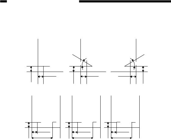
Stapling Positions (finisher unit)
1-point stapling (rear) |
1-point stapling |
1-point stapling |
|
(diagonal; front) |
(diagonal; rear) |
30
5±2mm |
6±2mm |
4.4±2mm |
|
|
4.5±2mm |
6±2mm |
30
4±2mm
2-point stapling
A3 and A4 |
B4 and B5 |
5±2mm |
202.7±4mm |
5±2mm |
182.7±4mm |
|
82.7±4mm |
|
62.7±4mm |
279 × 432 mm
(11 × 17), LTR
5±2mm |
73.7±4mm |
193.7±4mm |
Figure 1-201
1-4 |
COPYRIGHT © 1998 CANON INC. |
FINISHER-C1/SADDLE FINISHER-C2 REV. 0 DEC. 1998 PRINTED IN JAPAN (IMPRIME AU JAPON) |

CHAPTER 1 GENERAL DESCRIPTION
2.Saddle Stitcher Unit
Item |
|
Description |
|
|
|
Stapling method |
Center binding (double folding) |
|
|
|
|
Folding position |
See Figure 1-202. |
|
|
|
|
Paper size |
A3, B4, AR4, 297mm 432mm (11 17), LTRR |
|
|
|
|
Capacity |
15 sheets (including single cover page) |
|
|
|
|
Paper weight |
64 to 80 g (cover page up to 128 g) |
|
|
|
|
Stackihng capacity |
10 sets (stack of 11 to 15 sheets), 20 sets (stack of 6 to 10 sheets), |
|
|
25 sets (stack of 5 sheets or less) |
|
|
|
|
Stapling |
Stapling position |
2 points (center distribution; fixed interval) |
|
|
|
|
Staple accommodation |
2000 staples |
|
|
|
|
Staple supply |
Special cartridge |
|
|
|
|
Staples |
Special staples (Staple-D1) |
|
|
|
|
Staple detection |
Provided |
|
|
|
|
Manual stapling |
Not provided |
|
|
|
Folding |
Folding method |
Roller contact |
|
|
|
|
Folding mode |
Double folding |
|
|
|
|
Folding position |
Paper center |
|
|
|
|
Position adjustment |
Provided |
|
|
|
Power supply |
From finisher unit |
|
|
(24 V channel 2) |
|
|
|
|
Power consumption |
160 W or less |
|
|
|
|
Serial number |
ZLKxxxxx (Saddle Finisher-C2) |
|
|
|
|
Table 2-203
COPYRIGHT © 1998 CANON INC. |
FINISHER-C1/SADDLE FINISHER-C2 REV. 0 DEC. 1998 PRINTED IN JAPAN (IMPRIME AU JAPON) |
1-5 |
CHAPTER 1 GENERAL DESCRIPTION
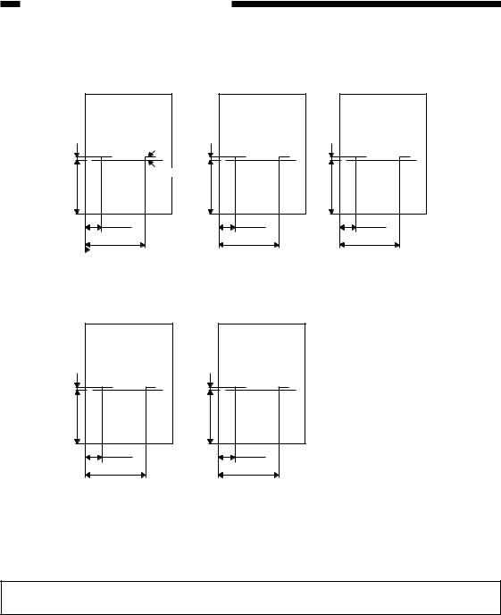
Staple and Folding Positions (saddle stitcher unit)
|
A3 |
|
|
Staple position |
|
L |
|
L |
210±1.5mm |
Folding position |
182±1.5mm |
|
||
|
83.5±1.5mm |
|
|
203.5±1.5mm |
|
 Stack front edge
L (difference between folding and staple positions) =
±0.5mm
B4 |
63.5±1.5mm |
183.5±1.5mm |
L (difference between folding and staple positions) =
±0.5mm
A4R |
148.5±1.5mmL |
40±1.5mm |
160±1.5mm |
L (difference between folding and staple positions) =
±0.5mm
297mm × 432mm |
(11 × 17) |
L |
216±1.5mm |
74.7±1.5mm |
194.7±1.5mm |
L (difference between folding and staple positions) =
±0.5mm
LTR |
L |
139.7±1.5mm |
43±1.5mm |
163±1.5mm |
L (difference between folding and staple positions) =
±0.5mm
Figure 1-202
Specifications are subject to change without notice.
1-6 |
COPYRIGHT © 1998 CANON INC. |
FINISHER-C1/SADDLE FINISHER-C2 REV. 0 DEC. 1998 PRINTED IN JAPAN (IMPRIME AU JAPON) |
CHAPTER 1 GENERAL DESCRIPTION
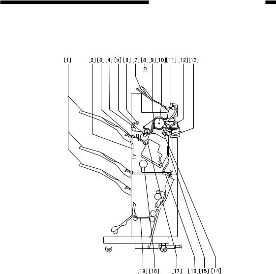
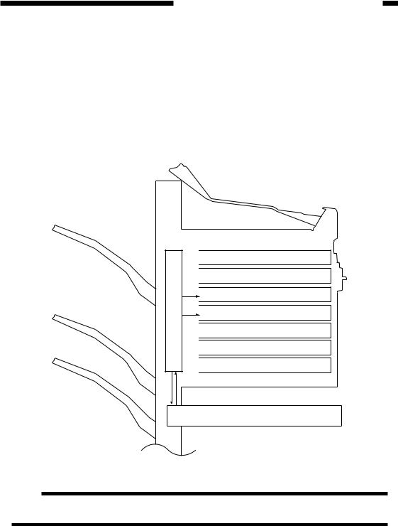
B.Cross Section
1.Finisher Unit
|
|
[11] Interrupt flapper |
|
|
|
|
|
|
[1] |
Tray 1/2/3 |
|
[2] |
Shutter |
[12] Buffer inlet flapper |
[3] |
Delivery roller |
[13] Saddle stitcher flapper |
[4] |
Jog guide |
[14] Feed roller 1 |
[5] |
Feed roller 2 |
[15] Vertical path |
[6] |
Height sensor |
[16] Stapler |
[7] |
Interrupt tray |
[17] Feed belt |
[8] Incoming fax indicator lamp |
[18] Tray lift motor |
|
|
(option; 115V) |
[19] Saddle stitcher unit |
[9] |
Wrap flapper |
(Saddle Finisher-C2) |
[10] Buffer roller |
|
|
Figure 1-203
COPYRIGHT © 1998 CANON INC. |
FINISHER-C1/SADDLE FINISHER-C2 REV. 0 DEC. 1998 PRINTED IN JAPAN (IMPRIME AU JAPON) |
1-7 |
CHAPTER 1 GENERAL DESCRIPTION
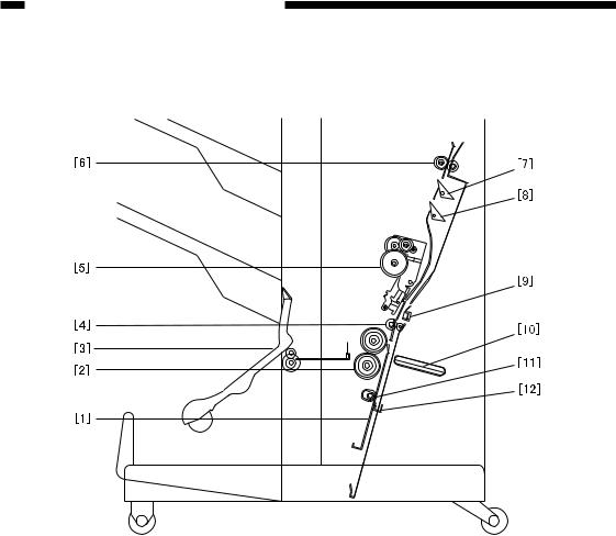
2.Saddle Stitcher Unit
[1] |
Guide plate |
[7] |
No. 1 flapper |
[2] |
Folding roller |
[8] |
No. 2 flapper |
[3] |
Delivery guide plate |
[9] Stitcher mount (front, rear) |
|
[4] |
Holding roller |
[10] Butting plate |
|
[5] |
Stitcher (front, rear) |
[11] |
Crescent roller |
[6] |
Inlet roller |
[12] |
Paper positioning plate |
Figure 1-204
1-8 |
COPYRIGHT © 1998 CANON INC. |
FINISHER-C1/SADDLE FINISHER-C2 REV. 0 DEC. 1998 PRINTED IN JAPAN (IMPRIME AU JAPON) |
III. Using the Machine
A.Removing Paper Jams from the Finisher Unit
If the copier indicates the finisher paper jam message, perform the following to remove the jam.
1)Holding the finisher unit as shown, move it to detach it from the copier.
Figure 1-301
2) Remove any jam visible from the outside.
Figure 1-302
CHAPTER 1 GENERAL DESCRIPTION
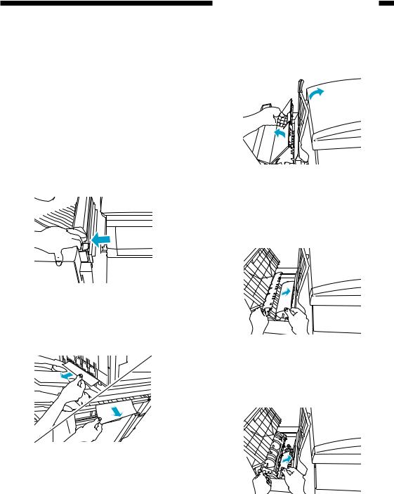
3)Shift up the interrupt tray, open the upper cover, and check the inside of the finisher.
Figure 1-303
4)Lift the buffer roller cover, and remove the jam.
Figure 1-304
5) Lift the buffer roller, and remove the jam.
Figure 1-305
COPYRIGHT © 1998 CANON INC. |
FINISHER-C1/SADDLE FINISHER-C2 REV. 0 DEC. 1998 PRINTED IN JAPAN (IMPRIME AU JAPON) |
1-9 |
CHAPTER 1 GENERAL DESCRIPTION
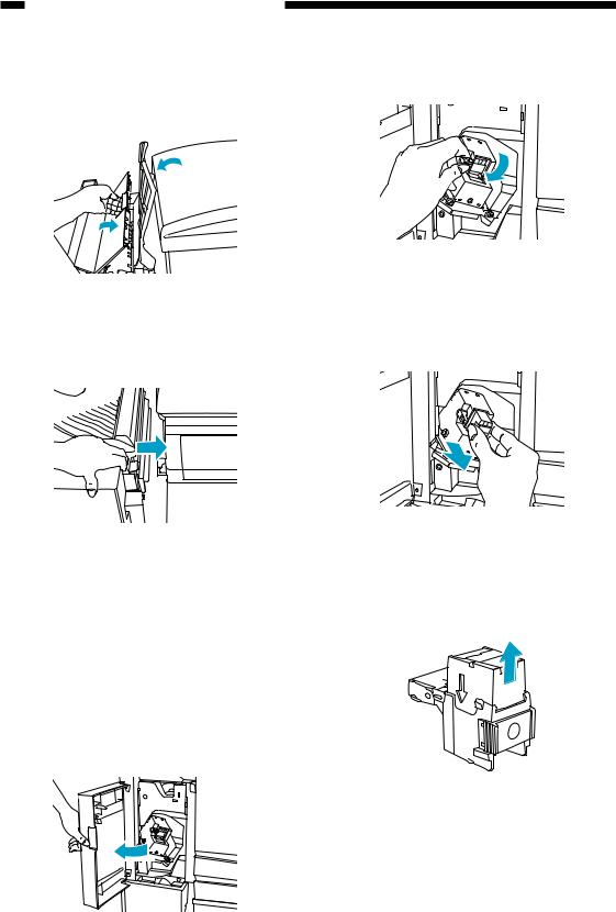
6)Return the buffer roller and the gray cover to their original position, and close the upper cover and the interrupt tray.
Figure 1-306
7) Connect the finisher to the copier.
Figure 1-307
8) Operate as instructed on the display.
2) Shift down the green lever.
Figure 1-309
3)When the staple cartridge has slightly slid out, hold and pull it out.
Figure 1-310
4)Hold the empty staple case on its sides, and slide it out.
B.Supplying the Finisher
Unit with Staples
If the copier indicates the finisher unit staple supply message, perform the following to supply it with staples.
Figure 1-311
Figure 1-308
1-10 |
COPYRIGHT © 1998 CANON INC. |
FINISHER-C1/SADDLE FINISHER-C2 REV. 0 DEC. 1998 PRINTED IN JAPAN (IMPRIME AU JAPON) |
CHAPTER 1 GENERAL DESCRIPTION
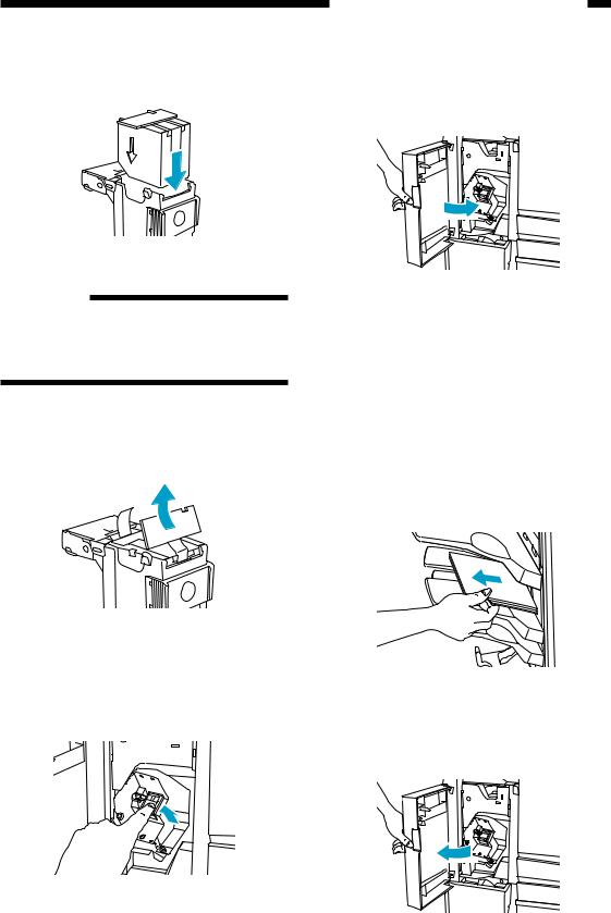
5) Set a new staple case.
Figure 1-312
Reference:
You may set no more than one staple cartridge at a time.
Make sure that the new cartridge is one specifically designed for the finisher unit.
6)Pull the length of tape (used to hold the staples in place) straight out.
Figure 1-313
7)Push in the stapler unit until the green lever returns to its original position.
Figure 1-314
8)Check to make sure that the stapler has been locked in place, and close the front cover.
Figure 1-315
C. Removing Staple Jams
from the Finisher Unit
If the copier indicates the finisher unit staple jam message, perform the following to remove the jam.
1)Remove the stack waiting to be stapled from the delivery tray.
Figure 1-316
2) Open the front cover.
Figure 1-317
COPYRIGHT © 1998 CANON INC. |
FINISHER-C1/SADDLE FINISHER-C2 REV. 0 DEC. 1998 PRINTED IN JAPAN (IMPRIME AU JAPON) |
1-11 |
CHAPTER 1 GENERAL DESCRIPTION
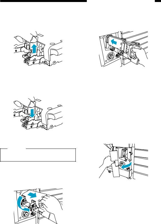
3) Shift down the green lever.
Figure 1-318
4)When the staple cartridge has slightly slid out, hold and pull it out.
Figure 1-319
5) Shift down the tab on the staple cartridge.
Figure 1-320
6)Remove all staples that have slid out of the staple case.
Figure 1-321
7)Return the tab on the staple cartridge to its original position.
8)Return the staple cartridge to its original position, and close the front cover.
Figure 1-322
Reference
When the cover has been closed, the stapler unit will automatically execute idle punching several times to advance the staples.
1-12 |
COPYRIGHT © 1998 CANON INC. |
FINISHER-C1/SADDLE FINISHER-C2 REV. 0 DEC. 1998 PRINTED IN JAPAN (IMPRIME AU JAPON) |

CHAPTER 1 GENERAL DESCRIPTION
D. Removing Paper Jams
from the Saddle Sticher
Unit
(Saddle Finisher-C2)
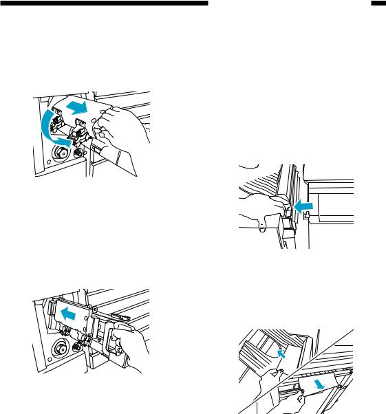
3) Turn the knob on the right side.
If the copier indicates the saddle stitcher unit paper jam message, perform the following to remove the jam.
1)Holding the saddle stitcher unit as shown, move it to detach it from the copier.
Figure 1-325
4) Turn the knob on the left side.
Figure 1-323
2) Open the front lower cover.
Figure 1-326
5) Remove the jam.
Figure 1-324
Figure 1-327
COPYRIGHT © 1998 CANON INC. |
FINISHER-C1/SADDLE FINISHER-C2 REV. 0 DEC. 1998 PRINTED IN JAPAN (IMPRIME AU JAPON) |
1-13 |

CHAPTER 1 GENERAL DESCRIPTION
6) Open the inlet cover, and remove the jam.
Figure 1-328
7) Close the front lower cover.
Figure 1-329
8)Connect the finisher unit.
9)Operate as instructed on the display.
E. Supplying the Saddle
Stitcher Unit with Staples
(Saddle Finisher-C2)
If the copier indicates the saddle stitcher unit staple supply message, perform the following to supply it with staples.
1) Open the front lower cover.
Figure 1-330
2) Slide out the stitcher unit.
Figure 1-331
3)Pull the stitcher unit to the front once, and then shift it up.
Figure 1-332
1-14 |
COPYRIGHT © 1998 CANON INC. |
FINISHER-C1/SADDLE FINISHER-C2 REV. 0 DEC. 1998 PRINTED IN JAPAN (IMPRIME AU JAPON) |
4)Hold the empty cartridge on its sides, and remove it.
Figure 1-333
5) Fit the new cartridge.
Figure 1-334
Caution:
You must always replace both cartridges at the same time.
6)Pull the stitcher to the front once, and then put it back to its original position.
Figure 1-335
CHAPTER 1 GENERAL DESCRIPTION
7)Push in the stitcher unit, and close the front cover.
Figure 1-336
F. Removing Staple Jams
from the Saddle Stitcher
Unit
(Saddle Finisher-C2)
If the copier indicates the saddle stitcher unit staple jam message, perform the following to remove the jam.
1) Open the front lower cover.
Figure 1-337
COPYRIGHT © 1998 CANON INC. |
FINISHER-C1/SADDLE FINISHER-C2 REV. 0 DEC. 1998 PRINTED IN JAPAN (IMPRIME AU JAPON) |
1-15 |

CHAPTER 1 GENERAL DESCRIPTION
2) Slide out the stitcher unit.
Figure 1-338
3)Pull the stapler of the stitcher unit to the front once, and then shift it up.
Figure 1-339
4)Hold the cartridge on its sides, and remove it.
Figure 1-340
5)Push down on the area identified as A, and pull up the tab identified as B.
B


 A
A
Figure 1-341
6)Remove the staple jam, and return the tab to its original position.
Figure 1-342
7) Return the cartridge to its original position.
Figure 1-343
1-16 |
COPYRIGHT © 1998 CANON INC. |
FINISHER-C1/SADDLE FINISHER-C2 REV. 0 DEC. 1998 PRINTED IN JAPAN (IMPRIME AU JAPON) |
8)Pull the stitcher of the stitcher unit to the front once, and then return it to its original position.
Figure 1-344
9)Push the stitcher unit back to its original position, and close the front lower cover. ï Whenever you have removed a staple jam, be sure to execute staple edging.
Figure 1-345
CHAPTER 1 GENERAL DESCRIPTION
G.Removing Paper Jams from the Interrupt Tray
If the display indicates a paper jam on the interrupt tray, perform the following to remove the jam:
1)Hold the finisher as shown, and detach it from the copier.
Figure 1-346
2) Remove the jam.
Figure 1-347
3)Connect the finisher to the copier.
4)Operate as instructed on the display.
COPYRIGHT © 1998 CANON INC. |
FINISHER-C1/SADDLE FINISHER-C2 REV. 0 DEC. 1998 PRINTED IN JAPAN (IMPRIME AU JAPON) |
1-17 |

CHAPTER 1 GENERAL DESCRIPTION
IV. MAINTENANCE BY THE USER
A.Maintenance by the User
|
|
As of April 1998 |
|
|
|
|
|
No. |
Item |
Timing |
|
|
|
|
|
1 |
Replacing the staple cartridge (finisher unit) |
When the appropriate indication is made on |
|
|
|
the copierís display. |
|
2 |
Replacing the staple cartridge (saddle stitcher) |
||
|
|||
|
|
|
Caution:
The finisher unit and the saddle unit use different cartridge types. Be sure that the appropriate type is used for each.
Table 1-401
1-18 |
COPYRIGHT © 1998 CANON INC. |
FINISHER-C1/SADDLE FINISHER-C2 REV. 0 DEC. 1998 PRINTED IN JAPAN (IMPRIME AU JAPON) |

CHAPTER 2
FINISHER UNIT BASIC OPERATION
I. BASIC OPERATION .................. |
2-1 |
A. Outline ................................. |
2-1 |
B. Outline of Electrical |
|
Circuitry................................ |
2-2 |
C. Inputs to and Outputs |
|
from the Finisher |
|
Controller PCB ..................... |
2-3 |
II. FEED/DRIVE SYSTEM ............. |
2-9 |
A. Outline ................................. |
2-9 |
B. Types of Delivery Paths ..... |
2-13 |
C. Feeding and Delivering ...... |
2-16 |
D. |
Job Offset .......................... |
2-19 |
E. |
Stapling Operation ............. |
2-22 |
F. |
Stapler Unit ........................ |
2-28 |
G. Tray Operation ................... |
2-35 |
|
H. Detecting the Height of the |
|
|
|
Stack on the Tray ............... |
2-37 |
I. |
Shutter Operation .............. |
2-39 |
J. |
Buffer Path Operation ........ |
2-43 |
K. Interrupt Tray Delivery ......... |
2-47 |
|
L. |
Detecting Jams .................. |
2-49 |
III. POWER SUPPLY SYSTEM .... |
2-55 |
|
COPYRIGHT © 1998 CANON INC. |
FINISHER-C1/SADDLE FINISHER-C2 REV. 0 DEC. 1998 PRINTED IN JAPAN (IMPRIME AU JAPON) |
CHAPTER 2 FINISHER UNIT BASIC OPERATION
I. BASIC OPERATION
A.Outline
The finisher is designed to deliver copies arriving from its host copier, and its modes of delivery include simple stacking, job offset, staple, and interrupt.
All operations involved in these modes are controlled by the finisher controller PCB, according to the appropriate commands from the host copier.
In the case of the Saddle Finisher-C2, copies from the host copier may be routed to the saddle stitcher unit.
Control system


 Swing guide drive system
 Alignment drive system

 Stapler drive system

 Delivery drive system
 Feeder drive system

 Shutter drive system
  Tray drive system
Saddle stitcher unit control system
Figure 2-101
Note:
The term job offset refers to shifting of the first sheet of each sorting job, thereby separating a single stack into several stacks.
COPYRIGHT © 1998 CANON INC. |
FINISHER-C1/SADDLE FINISHER-C2 REV. 0 DEC. 1998 PRINTED IN JAPAN (IMPRIME AU JAPON) |
2-1 |
CHAPTER 2 FINISHER UNIT BASIC OPERATION
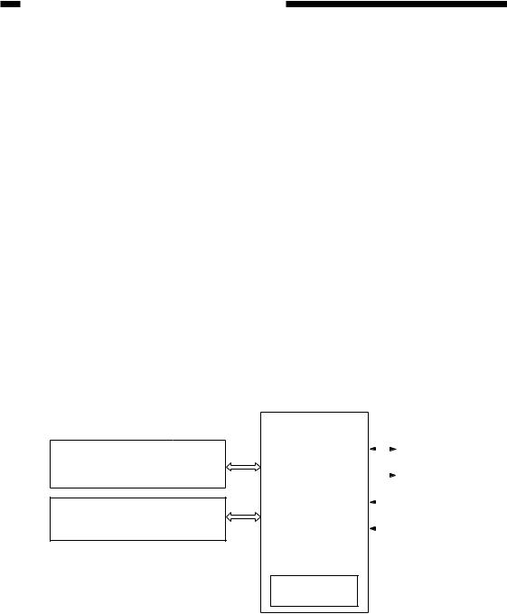
B.Outline of Electrical Circuitry
The finisherís sequence of operations is controlled by the finisher controller PCB. The finisher controller PCB is a 16-bit microprocessor (CPU), and is used for communication with the host copier (serial) in addition to controlling the finisherís sequence of operations.
The finisher controller PCB responds to the various commands coming from the host copier through a serial communications line to drive solenoids, motors, and other loads. In addition, it communicates the finisherís various states (information on sensors and switches) to the host copier through a serial communications circuit.
In the case of the Saddle Finisher-C2, the finisher controller PCB not only communicates with the saddle stitcher controller PCB but also communicates the saddle stitcher unitís various states (information on sensors and switches) to the host copier.
The ICs used on the finisher controller PCB are designed for the following: l Q1 (CPU)
Controls sequence of operations. l Q2 (EP-ROM)
Contains sequence programs. l Q3 (RAM)
Backs up initial settings data. l Q4 (communications IC)
Communicates with the host copier and the saddle stitcher unit.
lQ9 (regulator IC) Generates 5 V.
Figure 2-102 shows the flow of signals between the finisher and the options controller.
|
Finisher |
|
||||||
|
controller |
|
||||||
|
Motor |
|||||||
Saddle stitcher controller |
PCB |
|||||||
|
||||||||
PCB (Saddle Finisher-C2) |
|
|
|
|
|
|
|
|
Q1 |
|
|
|
|
|
Solenoid |
||
|
CPU |
|
|
|
|
|
||
|
|
|
||||||
|
|
|
|
|
|
|
|
|
Copier |
Q2 |
|
|
|
Switch |
|||
|
|
|||||||
EP-ROM |
|
|
|
|
|
|||
|
|
|||||||
|
|
|
|
|
|
|
||
(DC controller PCB CPU) |
Q3 |
|
|
|
|
Sensor |
||
|
|
|||||||
|
RAM |
|
|
|||||
|
|
|
|
|
|
|
||
|
|
|
||||||
|
Q4 |
|
|
|||||
|
Communications IC |
|
|
|||||
Q9
Regulator IC
Figure 2-102
2-2 |
COPYRIGHT © 1998 CANON INC. |
FINISHER-C1/SADDLE FINISHER-C2 REV. 0 DEC. 1998 PRINTED IN JAPAN (IMPRIME AU JAPON) |
Loading...