


Service Documentation |
Market Release 7/84 |
|
|
|
|
Braun Kitchen machine |
KM 32 B |
4209 |
with lamp |
|
|
|
|
|
4209

BINC Rev: 7/96 |
Service Documentation |
|
Exploded Drawing |
BAG Rev: 7/84 |
4209 |
|
|
4209 - 2

BINC Rev: 7/96 |
Service Documentation |
|
|
Service Information |
|
BAG Rev: 12/88 |
|
4209 |
|
|
|
Pos. No. |
Part Description |
Part Number |
1 |
Male drive coupling |
4207100 |
2 |
Upper housing |
4207923 |
3 |
Attachment cone |
4207199 |
4 |
Screw |
0033120 |
5 |
Pivon |
4207131 |
6 |
Screw |
0003302 |
7 |
Lower housing |
4209875 |
8 |
Screw |
0001500 |
9 |
Stop screw |
4207500 |
10 |
Protective sleeve |
4209003 |
11 |
Mains lead |
4390264 |
12 |
Cable clamp |
4206149 |
12a |
Cable clamp for pos. 12 |
4203051 |
13 |
Screw |
0003170 |
14 |
Switch knob |
4216193 |
15 |
Terminal block |
0717253 |
16 |
Screw |
0002706 |
17 |
Resistor |
0612717 |
18 |
Capacitor |
0622099 |
19 |
Glow lamp |
NLA |
20 |
Glow lamp holder |
4230051 |
21 |
Switch |
4230005 |
22 |
Bottom plate cpl. |
NLA |
23 |
Foot |
4243054 |
24 |
Screw |
0034115 |
25 |
Fan wheel |
4230002 |
26 |
Suspension of the motor |
4207534 |
27 |
Rubber buffer |
4230006 |
28a |
Washer |
0108111 |
28 |
Screw |
0003135 |
29 |
Screw |
0028101 |
30 |
Washer |
0102102 |
31 |
Motor |
4230550 |
32 |
Screw |
0030112 |
33 |
Upper end shield |
4250806 |
34 |
Rotor |
4230846 |
35 |
Washer |
4250016 |
36 |
Washer |
4250017 |
37 |
Stator |
4230847 |
38 |
Air baffle |
4250070 |
39 |
Thermo-switch |
NLA |
40 |
Tension spring for pos. 39 |
NLA |
4209 - 3
BINC Rev: 7/96 |
Service Documentation |
|
|
Spare Parts List |
|
BAG Rev: 12/88 |
|
4209 |
Pos. No. |
Part Description |
Part Number |
41 |
Carbon brush |
4250048 |
42 |
Fixing clamp |
4250047 |
43 |
Lower end shield |
4243817 |
44 |
Centering rubber |
4250045 |
45 |
Capacitor |
NLA |
46 |
Ferrite-tube |
4243078 |
- |
Insulating tube |
NLA |
- |
Plug junction |
0710127 |
- |
Double plug junction |
NLA |
- |
Wiring (w/ 1 slip on terminal) |
NLA |
- |
Wiring (w/ 2 slip on terminals) |
NLA |
- |
Type plate |
NLA |
|
Accessories |
|
|
Large mixing bowl |
4203014 |
|
Small mixing bowl |
4207055 |
|
Dough hook |
4207814 |
|
Whisk |
4207048 |
|
Whisk for whipped cream |
4207620 |
|
Circlip for whisk/hook |
4207530 |
|
Spatula |
4203118 |
|
Dust cover |
4203200 |
For additional attachment parts see page 16
4209 - 4
BINC Rev: 7/96 |
Service Documentation |
|
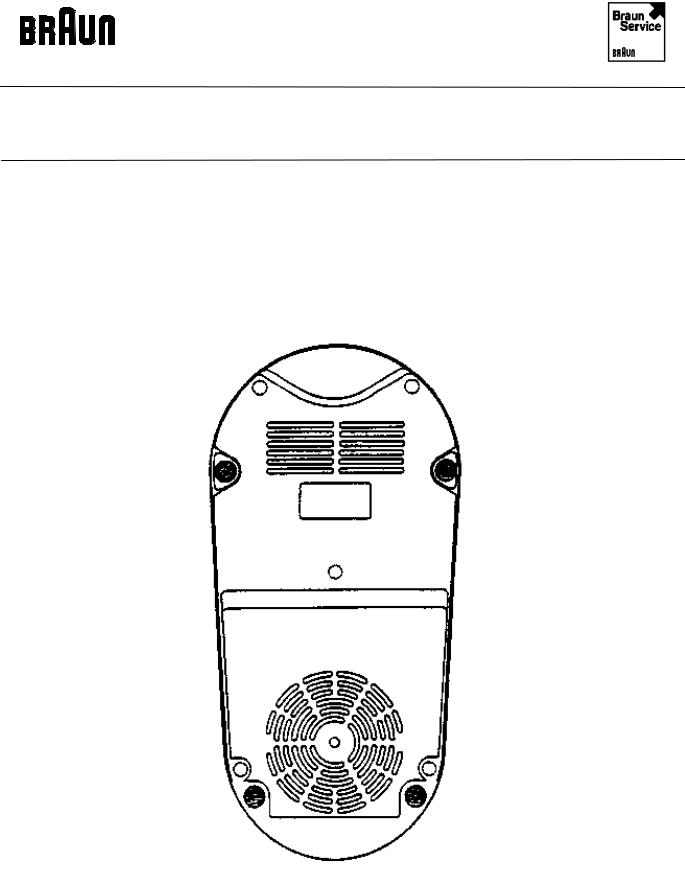
Reference Drawing |
BAG Rev: 7/84 |
4209 |
Bottom of the product
4209 - 5

BINC Rev: 7/96 |
Service Documentation |
|
Service Information |
BAG Rev: 12/88 |
4209 |
|
|
Technical Data |
|
Voltage/Frequency: |
110 V/120 V 40-60 Hz |
No-load power Position 1: |
appr. 125 W + 10 % |
Position 2: |
appr. 130 W + 10 % |
Position 3/L: |
appr. 205 W + 10 % |
No load speed Position 1: |
appr. 10700 min -1 |
Position 2: |
appr. 12500 min -1 |
Position 3/L: |
appr. 16000 min -1 |
Overheating protection: |
Thermo-switch/Fuse |
Length of mains lead: |
appr. 1.30 m |
Operating time: |
continuous operation at 400W |
4209 - 6

BINC Rev: 7/96 |
Service Documentation |
|
Service Information |
BAG Rev: 7/84 |
4209 |
|
|
1.Removal of motor (31)
Disconnect appliance mains plug from the socket. Loosen the holding screws from the bottom cover plate (22) and remove plate. Then withdraw the male-drive coupling (1) with the aid of an angle-shaped screw-driver.
Draw off switch knob (14) and unscrew switch securing screws (8, 9). Proceed by disconnecting the motor wiring on the terminal block (15). Subsequently loosen the 4 screws (28) with a long screw-driver and take the motor together out of the housing.
2.Reassembly
The reassembly is carried out in the reverse order, however attention should be paid to the rubber buffer (27).
The motor shaft must be supported at the bottom end, when the new male drive coupling (1) is mounted onto the shaft. Pay attention to the wiring diagram.
3.Replacement of the thermo-switch (39)
Remove motor (31) as described in paragraph 1.
Withdraw the air baffle (38) and loosen spring (40). Continue by disconnecting the plug connection on switch (21) and also connection on the terminal block (15) and install new thermo-switch.
4.Dismantling of motor (31)
With the aid of a screwdriver, push off the fan wheel (25).
Before starting to dismantle the motor, mark the latter in the longitudinal direction, so that all parts are again placed correctly left to right during the assembly. Use a 8 mm box spanner for removing screws (32). Before the motor is taken apart, first remove the carbon brushes (41). Prior to removing the brushes, loosen the fixing clips (42) at the sides and withdraw carefully.
5.Carry out a functional test
4209 - 7
BINC Rev: 7/96 |
Service Documentation |
|
Reference Drawing |
BAG Rev: 7/84 |
4209 |
|
|
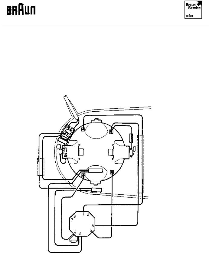
Wiring with thermo-switch
4209 - 8
BINC Rev: 7/96 |
Service Documentation |
|
Reference Drawing |
BAG Rev: 7/84 |
4209 |
|
|
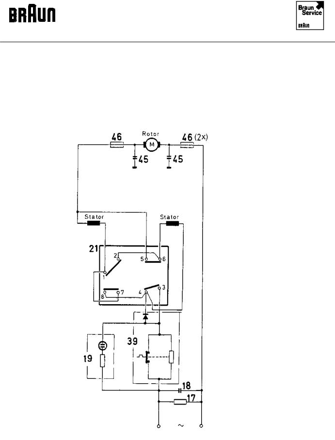
Wiring diagram
4209 - 9
 Loading...