


Operator's Manual
Braun Millennium SeriesTM 06 Wheelchair Lifts |
For ADA COMPLIANCE |
Operator's Manual for:
Series 06
Commercial
Wheelchair Lifts
®
"Providing Access to the World"®
International Corporate Hdqrs: P.O. Box 310 |
Winamac, IN 46996 |
USA |
|
1-800-THE LIFT |
(574) 946-6153 |
FAX: (574) 946-4670 |
|
|
Patent #5,261,779 |
Patent #6,238,169 |
25521-06 |
Patent #5,806,632 |
Patent #6,464,447 |
|
Patents Pending |
|
January 2003 Patent #6,065,924 |
||
WARNING |
Operator's |
|||||
O |
|
|
|
|
|
|
p |
e |
|
|
|
|
|
|
r |
|
|
|
|
|
|
|
a |
|
|
|
|
|
|
t |
|
|
|
|
Man |
|
o |
|
Manual |
||
|
|
r |
||||
|
|
' |
||||
|
|
|
s |
|||
|
u |
|
|
|
||
|
|
al |
|
|
||
|
|
|
|
|
|
|
Read manual |
|
|
|
|
Braun |
|
before operating |
||||||
lift. Failure to do |
||||||
so may result in |
|
|||||
|
SeriesMillennium |
|||||
serious bodily |
|
|
|
|||
injury and/or |
|
|
|
|
||
property damage. |
||||||
Keep manual in |
|
|||||
lift storage pouch. |
||||||
Americans With |
||||||
complying with ADA Disabilities Act |
TM |
|||||
|
||||||

Congratulations
We at The Braun Corporation wish to express our fullest appreciation on your new purchase. With you in mind, our skilled craftsmen have designed and assembled the finest lift available.
This manual includes safety precautions, lift operating instructions, manual operating instructions, and instructions for maintenance and lubrication procedures.
Your lift is built for dependability, and will bring you years of pleasure and independence, as long as maintenance is performed regularly and the lift is operated by an instructed person.
Sincerely,
THE BRAUN CORPORATION
Ralph W. Braun
Chief Executive Officer
Contents
Lift Terminology |
|
Introduction ............................................................... |
2 |
Direction .................................................................... |
3 |
Lift Components .................................................... |
3, 4 |
Lift Actions and Functions ......................................... |
5 |
Lift Terminology Illustrations |
|
Automatic Inboard Roll Stop “IB” ........................ |
6 |
Fixed Inboard Roll Stop “Non-IB” ........................ |
7 |
Lift Operation Safety |
|
Safety Symbols ......................................................... |
8 |
Lift Operation Safety Precautions ....................... |
9-12 |
Pre-Lift Operation Notes and Details |
|
Lift Access Doors and Lift Interlocks ....................... |
13 |
General Safety ......................................................... |
14 |
Lift Control Switches ............................................... |
14 |
Lift Features |
|
Lift-Tite Latches™ ........................................ |
15, 16 |
Bridge Plates and Inboard Roll Stops .......... |
17-19 |
Automatic Outboard Roll Stop .................... |
20, 21 |
Roll Stop Latch ................................................. |
21 |
Outboard Roll Stop and Roll Stop |
|
Latch Operation ................................................ |
21 |
Bridging ............................................................. |
21 |
Handrails ...................................................... |
21, 22 |
Lift Passengers |
|
Passenger Orientation (Boarding Direction) ..... |
22 |
Standees ........................................................... |
23 |
Yellow Boundaries ............................................ |
23 |
Vehicle (Floor Level) Loading and |
|
Unloading ................................................... |
23, 24 |
Wheelchair-Equipped Occupant Seat Belts ........... |
25 |
Operation Procedure Review ........................... |
25, 26 |
Preventive Maintenance ......................................... |
26 |
Lift Operating Instructions ............................. |
27-31 |
Manual Operating Instructions ....................... |
32-34 |
Decals and Antiskid ....................................... |
35-37 |
Maintenance and Lubrication ........................ |
38, 39 |
Warranty/Registration Instructions ............... |
40, 41 |
Page 1

Lift Terminology
Introduction: |
bridge plate details follow. |
|
|
Braun L915 Millennium Series lifts are ADA compliant and commercial oriented (intended for operation by an attendant). The L915 Millennium Lift Series includes variations of lift models L915, L916, L917, L918 and L919. Model numbers indicate lift dimensions and options.
Lift model numbers with suffix “IB” are equipped with an automatic mechanical inboard roll stop that also serves as the bridge plate (shown in the Lift Terminology Illustration on page 6). Lift model numbers without suffix “IB” feature a combination stationary inboard roll stop with an independent hinged bridge plate. Inboard roll stop and
L915 Series lift models can be equipped with left or right side pump modules as needed. Lift model numbers with suffix “F” are right side (front) pump-equipped and model numbers without suffix “F” are equipped with a left side (rear) pump. Left side pumpequipped lift models are depicted in both Lift Terminology Illustrations. Right side pump lift models are a mirrored image of rear pump models (pump module located on opposite end of base plate).
Refer to the Lift Terminology Illustrations for the visual differences in lift configurations and identification of lift components.
Lift operation procedures are identical for all L915 Series lift models. The operating instructions contained in this manual and appearing on lift-posted operating instructions decals address the lift control switches and the corresponding lift functions. Instructions are provided for manual operation of the lift in event of power or equipment failure.
Terminology: Become familiar with the terminology that will be used throughout this manual.
Become familiar with the identification of lift components and their functions. Contact your lift sales representative or call The Braun Corporation at 1-800-THE LIFT if any of this information is not fully understood.
Page 2

Direction: The terms "left (rear)," "right (front)," "inboard," and "outboard" will be used throughout this manual to indicate direction (as viewed from outside the vehicle looking directly at the lift). Refer to the Lift Terminology Illustrations for clarification of direction terms.
Lift Components
Refer to the Lift Terminology Illustrations on pages 6 and 7.
Pump Module: The lift-mounted pump module consists of the hydraulic pump, the manual hand pump and electrical components that power the lift electric/hydraulic systems.
Hand-Held Switch Control Box:
Lift Terminology
The “quick-disconnect” hand-held control switchbox is connected to the pump module. “Quickdisconnect” hand-held controls are available with three types of cable (standard, armored and coiled).
The control box is equipped with two color-coded rocker switches, (UNFOLD/FOLD and DOWN/UP). The switches activate the automatic lift functions. Details regarding the control switches and their functions are provided in the Pre-Lift Operation section (page 14).
Lift Frame: The lift frame consists of the base plate, two towers, the parallel arms, the vertical arms, platform pivot arms and the handrails. The two main
hydraulic cylinders are housed in the parallel arms. The electrical/ hydraulic powered lift frame components mechanically unfold, lower, raise and fold the lift platform assembly.
Platform Assembly: The lift platform assembly consists of the steel tubing frame with grating surface upon which the wheelchair is positioned, the outboard roll stop, roll stop latch, the inboard roll stop (fixed inboard roll stop models only), and the hydraulic cylinder assembly that powers the outboard roll stop.
Lift-Tite™ Latches: The spring loaded latches prevent the platform from unfolding from the stowed position in the event of platform drift. Further details
Page 3

Lift Terminology
Lift Components (continued)
regarding Lift-Tite™ latches are provided on pages 15 and 16.
Outboard Roll Stop: The cylinder-powered automatic outboard roll stop provides a ramp for wheelchair loading and unloading at ground level. Photos and further details regarding the outboard roll stop are provided in the Pre-Lift Operation Notes section (pages 20 and 21).
Roll Stop Latch: The springloaded latch locks the outboard roll stop in the vertical position when the platform raises above ground level.
Automatic Inboard Roll Stop and Bridge Plate (IB): L915 “IB” lift models are equipped with an automatic mechanical inboard roll stop that also serves as the bridge plate (shown in the Lift Terminology Illustration on page 6). The mechanical roll stop/ bridge plate automatically rotates from the horizontal (bridging) position to the vertical (roll stop) position as the lift lowers and raises. Further details regarding the automatic mechanical inboard roll stop are provided on pages 17 and 18.
Fixed Inboard Roll Stop: A stationary inboard roll stop is built into “non-IB” L915 lift platforms (shown in the Lift Terminology Illustration on page 7).
Independent Hinged Bridge Plate: “Non-IB” L915 lift models are equipped with an independent hinged bridge plate (shown in the Lift Terminology Illustration on page 7). The bridge plate bridges the gap between the lift platform and the vehicle floor. Further details regarding the bridge plate are provided on pages 17 and 18.
Page 4

Lift Actions and Functions
UNFOLD (Out) - Platform Unfold: Unfold is the action of the platform rotating out and down from the fully-stowed (vertical) position to floor level (horizontal) position when the UNFOLD switch is pressed.
DOWN - Platform Lower: Down is the action of the platform lowering from floor level position to fully-lowered (ground level) position when the DOWN switch is pressed.
DOWN - Roll Stop Unfold (Deploy) - When the platform reaches the fully-lowered (ground) position and the DOWN switch is continued to be pressed,
Lift Terminology
the outboard roll stop rotates downward from vertical position to ramp position.
UP - Roll Stop Fold (Raise):
When the lift is fully lowered and the roll stop is in the ramp position, pressing the UP switch first rotates the roll stop upward from ramp position to vertical position.
UP - Platform Raise: Up is the action of the platform raising from ground level to floor level (fullyraised) position when the UP switch is pressed.
FOLD (In) - Platform Fold: Fold is the action of the platform rotating up and in from the floor level (horizontal) position to fullystowed (vertical) position when
the FOLD switch is pressed.
Stowed Position: The lift is stowed when the lift platform has been fully raised and folded fully (vertical position).
Floor Level: Floor level is the position (height) the platform assembly reaches in order for the wheelchair passenger to enter and exit the vehicle (fully raised). The platform automatically stops at floor level when unfolding from the stowed position and when raising from ground level.
Note: Further details regarding lift control switches and the corresponding lift functions are provided in the Pre-Lift Operation Notes and Details section.
Page 5
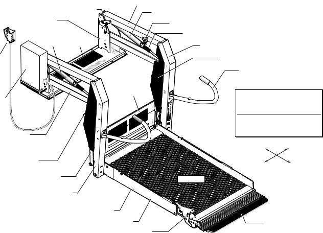
|
Lift-Tite™ |
Top Parallel Arms (2) |
|
Towers (2) |
Latches (2) |
|
Opposite Pump Side Cylinder |
|
|
||
(Upright Supports) |
|
|
Adjustable Quiet-Ride Bumper |
|
|
|
|
Pump Side |
Base |
|
Unfold Assist Compression Springs (2) |
Cylinder |
Plate |
|
Opposite Pump Side Vertical Arm |
|
|
||
Hand-Held |
|
|
Vertical Arm Covers (4) |
Attendant's |
|
Automatic |
Handrails (2) Note: Handrail |
Control Box |
|
||
|
Inboard Roll |
shape varies with lift model. |
|
|
|
||
Pump |
|
Stop and Bridge |
|
|
Plate (IB) |
Automatic Inboard |
|
Module |
|
||
|
|
||
(Rear) |
|
|
Roll Stop "IB" |
|
|
|
|
|
Lift Terminology |
|
Bottom Parallel |
Illustration |
|
|
|
|
Arms (2) |
Inboard |
Right (Front) |
Rotating Pivot |
|
|
Slide Arms (2) |
Left (Rear) |
Outboard |
|
||
Platform Pivot Arms (2) |
Platform |
|
Pump Side Vertical Arm |
|
|
Roll Stop Cylinder |
|
|
(not visible -underside of platform) |
Automatic Outboard |
|
Platform Side Plates (2) |
||
Roll Stop (ARS) |
||
Roll Stop Latch |
|
Page 6

|
Lift-Tite™ |
Top Parallel Arms (2) |
|
|
|
Towers (2) |
Latches (2) |
|
Opposite Pump Side Cylinder |
|
|
|
|
|
|
||
(Upright Supports) |
|
|
Adjustable Quiet-Ride Bumper |
|
|
|
|
|
|
||
Pump Side Base |
|
Unfold Assist Compression Springs (2) |
|||
Cylinder |
Plate |
|
Opposite Pump Side Vertical Arm |
||
|
|
||||
Hand-Held |
|
|
Vertical Arm Covers (4) |
||
Attendant's |
|
|
|
Handrails (2) |
Note: Handrail |
Control Box |
|
|
|
||
|
|
|
shape varies with lift model. |
||
|
|
|
|
||
Pump |
|
Independent |
|
Fixed Inboard |
|
Module |
|
|
|||
(Rear) |
|
Hinged |
Fixed Inboard |
Roll Stop "Non-IB" |
|
|
|
Bridge Plate |
Lift Terminology |
||
|
|
|
Roll Stop |
||
|
|
|
UHMW |
Illustration |
|
Bottom Parallel |
|
|
Platform |
||
|
|
|
|
||
Arms (2) |
|
|
Slides |
Inboard |
Right (Front) |
Rotating Pivot |
|
|
|
|
|
Slide Arms (2) |
|
|
|
Left (Rear) |
Outboard |
|
|
|
|
||
Platform Pivot Arms (2) |
Platform |
|
Pump Side Vertical Arm |
|
|
Roll Stop Cylinder |
|
|
(not visible -underside of platform) |
Automatic Outboard |
|
Platform Side Plates (2) |
||
Roll Stop (ARS) |
||
Roll Stop Latch |
|
|
|
Page 7 |

Lift Operation Safety
Safety Symbols
|
SAFETY FIRST! Know That.... |
|
|
|
|
|
|
|
|
|
|
|
|
|
|
All information contained |
|
|
|
|
|
|
|
|
|
|
|
|
A |
B |
|
|
WARNING |
|
|
C |
|
|
CAUTION |
|
|
|
in this manual and |
|
|
|
|
|
|
|
|||||
supplements (if included), is |
|
|
|
|
|
|
|
|
|
|
|
||
|
|
|
This symbol indicates |
|
|
|
|
|
This symbol indicates |
|
|||
provided for your safety. Famil- |
|
|
|
|
|
|
|
|
|
||||
iarity with proper operation |
|
|
|
important safety |
|
|
|
|
|
important information |
|
||
instructions as well as proper |
|
|
|
information regarding |
|
|
|
|
|
regarding how to |
|
||
maintenance procedures are |
|
|
|
a potentially hazard- |
|
|
|
|
|
avoid a hazardous |
|
||
necessary to ensure safe, |
|
|
|
ous situation that |
|
|
|
|
|
situation that could |
|
||
troublefree operation. Safety |
|
|
|
could result in serious |
|
|
|
|
|
result in minor per- |
|
||
precautions are provided to |
|
|
|
bodily injury and/or |
|
|
|
|
|
sonal injury or prop- |
|
||
identify potentially hazardous |
|
|
|
property damage. |
|
|
|
|
|
erty damage. |
|
||
situations and provide instruction |
|
|
|
|
|
|
|
|
|
|
|
||
|
|
|
|
|
|
|
|
|
|
|
|||
on how to avoid them. |
|
|
|
|
|
|
|
|
|
|
|
||
D Note: Additional information provided to help clarify or detail a specific subject.
These symbols will appear throughout this manual as well as on the labels posted on your lift. Recognize the seriousness of this information.
Page 8
Lift Operation Safety
Lift Operation Safety Precautions
 WARNING
If the lift operating instructions, manual operating instructions and/or lift operation safety precautions are not fully understood, contact The Braun Corporation immediately. Failure to do so may result in serious bodily injury and/or property damage.
 WARNING Read manual and supplement(s) before operating lift. Read and become familiar with all safety precautions, pre-lift operation notes and details, operating instructions and manual operating instructions before operating the lift. Note: Wheelchair passengers and all transit agency personnel (drivers and wheelchair lift attendants) must read and become familiar with the contents of this manual and supplement(s) before operation.
 WARNING
 WARNING
 WARNING
Load and unload on level surface only.
Engage vehicle parking brake before operating lift.
Provide adequate clearance outside the vehicle to accommodate the lift before opening lift door(s) or operating lift.
 WARNING Inspect lift before operation. Do not operate lift if you suspect lift damage, wear or any abnormal condition.
 WARNING Keep operator and bystanders clear of area in which the lift operates.
Page 9
Lift Operation Safety
Lift Operation Safety Precautions (continued)
 WARNING
If the lift operating instructions, manual operating instructions and/or lift operation safety precautions are not fully understood, contact The Braun Corporation immediately. Failure to do so may result in serious bodily injury and/or property damage.
 WARNING Whenever a wheelchair passenger (or standee) is on the platform, the:
•Passenger must be positioned fully inside yellow boundaries
•Wheelchair brakes must be locked
•Roll stops must be up (vertical)
•Roll stop latch must be fully engaged
•Passenger should grip both handrails (if able).
 WARNING Load and unload clear of vehicular traffic.
 WARNING Do not overload or abuse. The load rating applies to both the raising and lowering functions - continuous lifting capacity is 800 lbs.
 WARNING Do not operate or board the lift if you or your lift operator are intoxicated.
 WARNING Do not raise front wheelchair wheels (pull wheelie) when loading (boarding) the platform.
WARNING |
Open lift door(s) fully and secure before operating lift. |
Page 10

|
Lift Operation Safety |
WARNING |
Position and secure (buckle, engage, fasten, etc.) the wheelchair-equipped occupant seat |
|
belt (torso restraint) before loading onto the wheelchair lift platform. |
WARNING |
Lift attendants must ensure that lift occupants keep hands, arms and all other body parts |
|
within the lift occupant area and clear of moving parts. |
WARNING |
Platform must be positioned at floor level (bridge plate height) when loading or unloading |
|
in and out of vehicle. |
WARNING |
Do not use platform roll stops as a barrier (brake). Stop and brake wheelchair when |
|
loading onto the platform (manually stop and brake manual wheelchairs — stop powered |
|
wheelchairs with the wheelchair controls). |
WARNING |
Turn powered (electric) wheelchairs off when on lift platform. |
WARNING |
Press the DOWN switch until the entire platform rests on ground level (lowered fully) and |
|
the outboard roll stop is fully unfolded (ramp position) before loading or unloading a |
|
passenger at ground level. |
WARNING |
Outboard platform roll stop must be fully unfolded (ramp position) until front and rear |
|
wheelchair wheels cross roll stop when loading or unloading at ground level. |
WARNING |
Accidental activation of control switch(es) may cause unintended operation(s). |
Page 11

Lift Operation Safety
Lift Operation Safety Precautions (continued)
 WARNING
If the lift operating instructions, manual operating instructions and/or lift operation safety precautions are not fully understood, contact The Braun Corporation immediately. Failure to do so may result in serious bodily injury and/or property damage.
 WARNING Maintenance and lubrication procedures must be performed as specified in this manual by authorized (certified) service personnel.
 WARNING Replace missing, worn or illegible decals.
 WARNING Keep owner’s (operator's) manual in lift-mounted manual storage pouch at all times.
 WARNING Never modify (alter) a Braun Corporation lift.
 WARNING Do not use accessory devices not authorized by The Braun Corporation.
 WARNING Do not remove any guards or covers.
 WARNING Keep clear of any hydraulic leak.
 WARNING Failure to follow these safety precautions may result in serious bodily injury and/or property damage.
Page 12
 Loading...