


CONTENTS |
|
SAFETY INFORMATION ................................................................................................................... |
2 |
ELECTROSTATIC DISCHARGE SENSITIVE (ESDS) DEVICE HANDLING .................................. |
2 |
WARRANTY........................................................................................................................................ |
2 |
ELECTRICAL SPECIFICATIONS...................................................................................................... |
3 |
MECHANICAL SPECIFICATIONS..................................................................................................... |
4 |
PRODUCT DESCRIPTION ............................................................................................................... |
4 |
PART LIST NOTES ........................................................................................................................... |
4 |
PACKAGING PART LIST .................................................................................................................. |
5 |
Figure 1. Lifestyle® SA-2 Packaging View ......................................................................................... |
5 |
PACKAGING PART LIST .................................................................................................................. |
6 |
Figure 2. Lifestyle® SA-3 Packaging View ......................................................................................... |
6 |
MAIN PART LIST ............................................................................................................................... |
7 |
Figure 3. Lifestyle® SA-2 Exploded View ........................................................................................... |
7 |
MAIN PART LIST ............................................................................................................................... |
8 |
Figure 4. Lifestyle® SA-3 Exploded View ........................................................................................... |
8 |
ELECTRICAL PART LIST ................................................................................................................. |
9 |
SA-2 DISASSEMBLY PROCEDURES ............................................................................................ |
17 |
SA-3 DISASSEMBLY PROCEDURES ............................................................................................ |
19 |
TEST SET-UP ................................................................................................................................... |
22 |
TEST PROCEDURES ..................................................................................................................... |
23 |
Lifestyle® SA-2 & SA-3 Amplifier PCB Rev. 0 Topside Component and Etch Layout Diagram.......... |
24 |
Lifestyle® SA-2 & SA-3 Amplifier PCB Rev. 0 SMD Etch and Component Layout Diagram .............. |
25 |
CAUTION: The Bose® Lifestyle® SA-2 & SA-3 amplifiers contain no user-serviceable parts. To prevent warranty infractions, refer servicing to warranty service stations or factory service.
PROPRIETARY INFORMATION
THIS DOCUMENT CONTAINS PROPRIETARY INFORMATION OF BOSE CORPORATION WHICH IS BEING FURNISHED ONLY FOR THE PURPOSE OF SERVICING THE IDENTIFIED BOSE PRODUCT BY AN AUTHORIZED BOSE SERVICE CENTER OR OWNER OF THE BOSE PRODUCT, AND SHALL NOT BE REPRODUCED OR USED FOR ANY OTHER PURPOSE.
1

SAFETY INFORMATION
1.Parts that have special safety characteristics are identified by the 

 symbol on schematics or by special notes on the parts list. Use only replacement parts that have critical characteristics recommended by the manufacturer.
2.Make leakage current or resistance measurements to determine that exposed parts are acceptably insulated from the supply circuit before returning the unit to the customer. Refer to UL6500 clause 9.1.1. Use the following checks to perform these measurements:
A.Leakage Current Hot Check-With the unit completely reassembled, plug the AC line cord directly into a 120V AC outlet. (Do not use an isolation transformer during this test.) Use a leakage current tester or a metering system that complies with American National Standards Institute (ANSI) C101.1 "Leakage Current for Appliances" and Underwriters Laboratories (UL) 6500. With the unit AC switch first in the ON position and then in OFF position, measure from a known earth ground (metal waterpipe, conduit, etc.) to all exposed metal parts of the unit (antennas, handle bracket, metal cabinet, screwheads, metallic overlays, control shafts, etc.), especially any exposed metal parts that offer an electrical return path to the chassis. Any current measured must not exceed 0.5 milliamp. Reverse the unit power cord plug in the outlet and repeat test. ANY MEASUREMENTS NOT WITHIN THE LIMITS SPECIFIED HEREIN INDICATE A POTENTIAL SHOCK HAZARD THAT MUST BE ELIMINATED BEFORE RETURNING THE UNIT TO THE CUSTOMER.
B.Insulation Resistance Test Cold Check-(1) Unplug the power supply and connect a jumper wire between the two prongs of the plug. (2) Turn on the power switch of the unit. (3) Measure the resistance with an ohmmeter between the jumpered AC plug and each exposed metallic cabinet part on the unit. When the exposed metallic part has a return path to the chassis, the reading should be between 1 and 5.2 Megohms. When there is no return path to the chassis, the reading must be "infinite". If it is not within the limits specified, there is the possibility of a shock hazard, and the unit must be repaired and rechecked before it is returned to the customer.
ELECTROSTATIC DISCHARGE SENSITIVE (ESDS)
DEVICE HANDLING
This unit contains ESDS devices. We recommend the following precautions when repairing, replacing or transporting ESDS devices:
•Perform work at an electrically grounded work station.
•Wear wrist straps that connect to the station or heel straps that connect to conductive floor mats.
•Avoid touching the leads or contacts of ESDS devices or PC boards even if properly grounded. Handle boards by the edges only.
•Transport or store ESDS devices in ESD protective bags, bins, or totes. Do not insert unprotected devices into materials such as plastic, polystyrene foam, clear plastic bags, bubble wrap or plastic trays.
WARRANTY
The Bose® Lifestyle® SA-2 and SA-3 amplifiers are covered by a limited one year transferable warranty.
2
ELECTRICAL SPECIFICATIONS
Voltage Variations: |
US: |
|
International: |
Maximum Power: |
SA-2: |
|
SA-3: |
Frequency Response: |
|
Dynamic Equalization: |
|
Voltage Gain (at 1 kHz): SA-2:
SA-3:
Input Impedance at (at 1 kHz):
Signal to Noise Ratio:
Input Sensitivity:
Compressor: |
Range: |
|
Attack Time: |
|
Release Time: |
|
Distortion: |
Turn-On Delay (to unmute):
Volume Control Range:
Output DC offset:
Channel Balance:
Output Short-Curcuit Duration:
Standby Power Consumption:
120 Vrms
220-240 Vrms
40 Watts into 6 Ohms @ <0.1% THD
20 Hz to 10kHz
100 Watts into 6 Ohms @ < 0.2%THD
20 Hz to 10 kHz
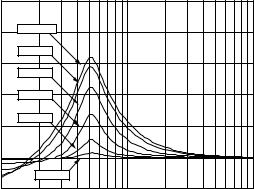
20 Hz - 20 kHz,+/- 0.5 dB |
(at full volume) |
|
||||
|
25 |
|
|
|
|
|
|
20 |
|
<40 dB SPL |
|
|
|
|
|
|
|
|
|
|
R |
|
|
50 dB SPL |
|
|
|
|
|
|
|
|
|
|
E |
15 |
|
|
|
|
|
S |
|
|
|
|
|
|
|
|
60 dB SPL |
|
|
|
|
P |
|
|
|
|
|
|
O |
|
|
|
|
|
|
N |
|
|
|
|
|
|
S |
10 |
|
70 dB SPL |
|
|
|
E |
|
|
|
|
|
|
: |
|
|
|
|
|
|
: |
|
|
80 dB SPL |
|
|
|
D |
|
|
|
|
|
|
5 |
|
|
|
|
|
|
B |
|
|
|
|
|
|
|
0 |
|
|
|
|
|
|
|
|
90 dB SPL |
|
|
|
|
-5 |
|
|
|
|
|
|
1E |
1 |
1E |
2 |
1E |
3 |
FREQUENCY--HERTZ
34.2 dB +/- 0.5 dB
38.2 dB +/- 0.5 dB
10 k +/- 1 Ohms
92 dB
0.3 Vrms at full volume produces rated output power
18 dB (minimum)
1 dB/ 700uS
1 dB/10 mS
<2%THD @100 Hz, 18 dB into compression
1 second maximum at initial turn-on
0.2 second maximum from standby
0 to -80 dB in 1 dB steps
<20 mVdc +/- 0.5 dB
Infinite (with no damage)
<1 Watts (real power) at rated line voltage
3

MECHANICAL SPECIFICATIONS
Quiescent ON Power Consumption: |
SA-2: |
< 10 Watts |
|
|
|
SA-3: |
< 15 Watts |
Maximum Power Consumption: |
SA-2: |
< 220 Watts |
|
|
|
SA-3: |
< 400 Watts |
Size: |
|
SA-2: 3½”H x 14 1/8”W x 5½”D |
|
|
|
|
(8.9cm x 35.9cm x 14cm) |
|
|
SA-3: 4¼”H x 14 1/8”W x 5½”D |
|
|
|
|
(11.4cm x 35.9cm x 14cm) |
Weight; shipping: |
|
SA-2: 7.6 lbs. (3.4 kg) |
|
|
|
SA-3: 11.1 lbs. (5 kg) |
|
Enclosure Material: |
Housing: |
|
Die cast aluminum (A360) |
|
Bottom: |
|
20 Ga. steel plate |
|
Finish: |
|
Textured black powdercoat |
Controls: |
|
|
Power switch (International version only) |
|
|
|
Voltage select switch (Dual Voltage version |
|
|
|
only) |
PRODUCT DESCRIPTION
The SA-2 Amplifier is a 2 x 40W stereo audio amplifier intended to power Bose® 161™, 191, 201®, or AM-3 indoor “zone 2” loudspeakers. It is the next generation version of SA-1, updated to work with the next generation media centers. It recognizes and responds to smart speaker II protocol commands. The SA-3 Amplifier is a 2 x 100W stereo audio amplifier intended to power Bose high SPL passive loudspeakers which can be used in second zone applications, specifically, 251® or FS-51 (outdoor), AM-5® or 301® (indoor). SA-3 is the higher power version of SA-2, with two additional features: local audio source input and mono/stereo switch. The SA-3 recognizes and responds to smart speaker I (CD-5, CD-20, MRI) or II (AV18 and AV48) protocol commands.
PART LIST NOTES
1.This part is not normally available from Customer Service. Approval from the Field Service Manager is required before ordering.
2.The individual parts located on the PCBs are listed in the Electrical Part List.
3.

 This part is critical for safety purposes. Failure to use a substitute replacement with the
same safety characteristics as the recommended replacement part might create shock, fire and/or other hazards.
4
PACKAGING PART LIST
Reference |
Description |
Part Number |
Note |
Designator |
|
|
|
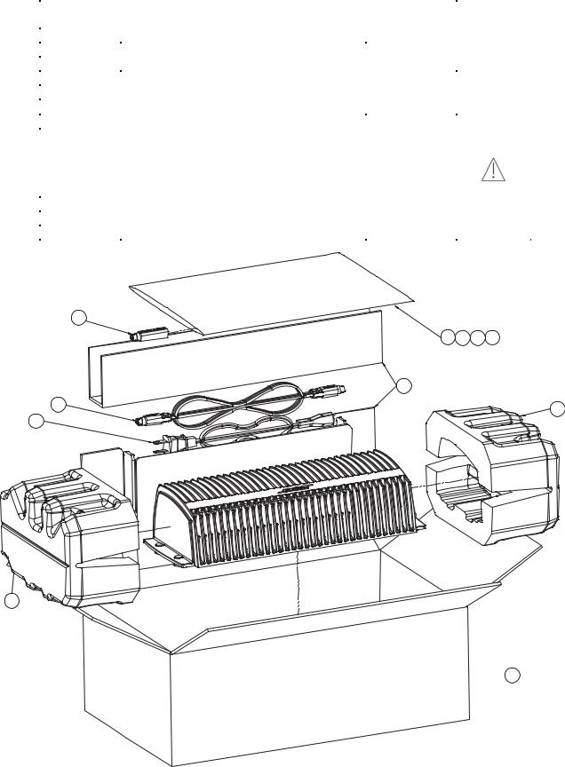
1 |
8 TO 9 PIN DIN ADAPTER |
273263 |
|
2 |
BAG, POLY, 14 3/8X9 7/8X2 MIL |
103351 |
|
3 |
REGISTRATION & WARRANTY CARD |
262933 |
|
4 |
SHEET, SAFETY |
275072 |
|
5 |
OWNERS MANUAL, 3 LANGUAGE |
275071 |
|
6 |
PACKING, INSERT |
275424 |
|
7 |
CABLE, DIN-9, 20FT |
272902-220 |
|
8 |
LINE CORD, DETACH, BLK |
|
|
|
US/DUAL VOLTAGE |
198603-001 |
3 |
|
220-240V, EURO |
148203 |
|
|
240V, UK |
134725 |
|
|
240V, AUS |
134726 |
|
9 |
PACKING, END CAP, EPS |
275423 |
|
10 |
CARTON, RSC |
275422 |
|
-- |
BAG, POLY, 12X20X4 MIL |
197405 |
|
1 |
|
|
|
2 |
3 |
4 |
5 |
6 |
|
|
|
7 |
|
|
9 |
8 |
|
|
|
|
|
|
9
 10
10
Figure 1. Lifestyle® SA-2 Packaging View
5
PACKAGING PART LIST
Reference |
Description |
Part Number |
Note |
Designator |
|
|
|
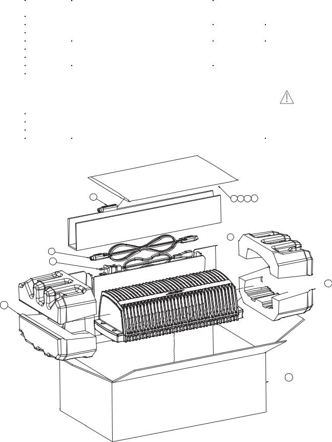
1 |
8 TO 9 PIN DIN ADAPTER |
273263 |
|
2 |
BAG, POLY, 14 3/8X9 7/8X2 MIL |
103351 |
|
3 |
REGISTRATION & WARRANTY CARD |
262933 |
|
4 |
SHEET, SAFETY |
275072 |
|
5 |
OWNERS MANUAL, 3 LANGUAGE |
275071 |
|
6 |
PACKING, INSERT |
275424 |
|
7 |
CABLE, DIN-9, 20FT |
272902-220 |
|
8 |
LINE CORD, DETACH, BLK |
|
|
|
US/DUAL VOLTAGE |
198603-001 |
3 |
|
220-240V, EURO |
148203 |
|
|
240V, UK |
134725 |
|
|
240V, AUS |
134726 |
|
9 |
PACKING, END CAP, EPS |
275423 |
|
10 |
CARTON, RSC |
276289 |
|
-- |
BAG, POLY, 12X20X4 MIL |
197405 |
|
1 |
2 3 4 5 |
 6
6
7 8


 9
9
9 
 10
10
Figure 2. Lifestyle® SA- 3 Packaging View
6
MAIN PART LIST
Reference |
Description |
|
|
Part Number |
Qty. |
Note |
Designator |
|
|
|
|
|
|
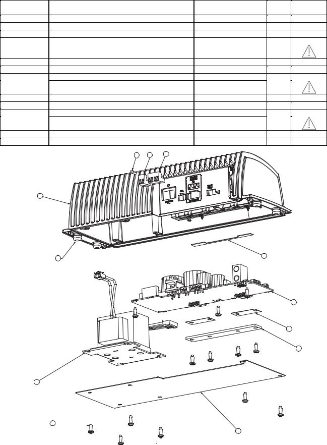
1 |
CONNECTOR, PLUG-IN, 4 PIN |
|
|
272953-04 |
1 |
|
2 |
CONNECTOR, PLUG-IN, 2 PIN |
|
|
272953-02 |
1 |
|
3 |
SCREW, HILO, 4-16x.375, PAN, XREC |
181621-06 |
1 |
|
||
4 |
HOUSING, AMPLIFIER |
|
|
271724-02 |
1 |
1 |
5 |
FOOT, RUBBER, PRESS FIT |
|
|
197418 |
4 |
|
6 |
TAPE, PAD, INSULATING |
|
|
328907-0010 |
1 |
|
7 |
PCB ASSY, US/CANADA, 120V |
|
288296-103S or 323980-011S |
1 |
2 |
|
|
PCB ASSY, EURO, UK, AUS, 220/240V 303198-203S or 323981-012S |
|
|
|||
8 |
PAD, THERMAL, AMP |
|
|
320002-002 |
2 |
|
9 |
HEATSINK BAR |
|
|
319884-001 |
|
|
10 |
TRANSFORMER, 120V |
|
|
271727 |
1 |
3 |
|
TRANSFORMER, 230V |
|
|
271790 |
|
|
11 |
PANEL, BOTTOM |
|
|
271725-001 |
1 |
|
12 |
SCREW, TT, 8-32X0.5, PAN, XREC/SQ |
255191-08 |
13 |
|
||
|
3 |
2 |
1 |
|
|
|
4
5 |
6 |
|
7
8
9
10
12


11
Figure 3. Lifestyle® SA-2 Exploded View
7

MAIN PART LIST
Reference |
Description |
|
|
Part Number |
Qty. |
Note |
Designator |
|
|
|
|
|
|
1 |
CONNECTOR, PLUG-IN, 4 PIN |
|
272953-04 |
1 |
|
|
2 |
CONNECTOR, PLUG-IN, 2 PIN |
|
272953-02 |
1 |
|
|
3 |
SCREW , HILO, 4-16x.375, PAN, XREC |
181621-06 |
2 |
|
||
4 |
HOUSING, AMPLIFIER |
|
|
271724-03 |
1 |
1 |
5 |
FOOT, RUBBER, PRESS FIT |
|
|
197418 |
4 |
|
6 |
TAPE, PAD, INSULATING |
|
|
328907-0020 |
1 |
|
7 |
PCB ASSY, US/CANADA, 120V 288286-103S or 323982-011S |
1 |
2 |
|||
|
PCB ASSY, EURO, UK, AUS, 220/240V 303199-203S or 323983-012S |
|
||||
8 |
PAD, THERMAL, AMP |
|
|
320002-001 |
1 |
|
9 |
HEAT SINK BAR |
|
|
319832-001 |
|
|
10 |
TRANSFORMER, 120V |
|
|
271728 |
1 |
3 |
|
TRANSFORMER, 230V |
|
|
271792 |
|
|
11 |
HOUSING, BOTTOM |
|
|
271726-001 |
1 |
|
12 |
SCREW , TT, 8-32X0.5, PAN, XREC/SQ |
255191-08 |
16 |
|
||
|
2 |
1 |
3 |
|
|
|
|
|
|
|
|
|
|
4
6


 7
7
8
9
12
10
11
5
Figure 4. Lifestyle® SA-3 Exploded View
8

ELECTRICAL PART LIST
Resistors
Reference |
Description |
Part Number |
Note |
Designator |
|
|
|
RT1 |
THERMISTOR, 0805, 10K, 5% |
197229 |
SA-3 Only |
RT2 |
THERMISTOR, 0805, 10K, 5% |
197229 |
|
RT3 |
THERMISTOR, 0805, 10K, 5% |
197229 |
|
R1 |
100 OHM, 0603, .1W, 1% |
191465-1000 |
|
R2 |
10K, 0603, .1W, 1% |
191465-1002 |
|
R3 |
10K, 0603, .1W, 1% |
191465-1002 |
|
R4 |
100K, 0603, .1W, 1% |
191465-1003 |
|
R5 |
4.02K, 0603, .1W, 1% |
191465-4021 |
|
R6 |
4.02K, 0603, .1W, 1% |
191465-4021 |
SA-3 Only |
R7 |
100K, 0603, .1W, 1% |
191465-1003 |
SA-3 Only |
R8 |
JUMPER, 0805 |
133627 |
|
R9 |
499 OHM, 0603, .1W, 1% |
191465-4990 |
|
R10 |
220 OHM, 2512, 1W, 5% |
181895-2200 |
120V Only |
|
470 OHM, 2512, 1W, 5% |
181895-4700 |
230V Only |
R11 |
10K, 0603, .1W, 1% |
191465-1002 |
|
R12 |
200 OHM, 0603, .1W, 1% |
191465-2000 |
|
R13 |
432 OHM, 0603, .1W, 1% |
191465-4320 |
|
R14 |
2.0K, 0603, .1W, 1% |
191465-2001 |
|
R15 |
10K, 0603, .1W, 1% |
191465-1002 |
|
R16 |
10K, 0603, .1W, 1% |
191465-1002 |
|
R17 |
2.0K, 0603, .1W, 1% |
191465-2001 |
|
R18 |
100K, 0603, .1W, 1% |
191465-1003 |
|
R19 |
100K, 0603, .1W, 1% |
191465-1003 |
|
R20 |
1.0K, 0603, .1W, 1% |
191465-1001 |
|
R21 |
1.0K, 0603, .1W, 1% |
191465-1001 |
SA-3 Only |
R22 |
10K, 0603, .1W, 1% |
191465-1002 |
|
R23 |
100 OHM, 0603, .1W, 1% |
191465-1000 |
|
R24 |
100 OHM, 0603, .1W, 1% |
191465-1000 |
|
R25 |
10K, 0603, .1W, 1% |
191465-1002 |
|
R26 |
100 OHM, 0603, .1W, 1% |
191465-1000 |
|
R27 |
100 OHM, 0603, .1W, 1% |
191465-1000 |
|
R28 |
100K, 0603, .1W, 1% |
191465-1003 |
|
R29 |
100K, 0603, .1W, 1% |
191465-1003 |
|
R30 |
100K, ARRAY, SMT, 4 POS, 5% |
186433-1044 |
|
R31 |
20.0K, 0603, .1W, 1% |
191465-2002 |
|
R32 |
100K, 0603, .1W, 1% |
191465-1003 |
|
R33 |
200K, 0603, .1W, 1% |
191465-2003 |
|
R35 |
13.3K, 0603, .1W, 1% |
191465-1332 |
|
R36 |
1.0K, 0603, .1W, 1% |
191465-1001 |
|
R37 |
4.99K, 0603, .1W, 1% |
191465-4991 |
|
R38 |
4.99K, 0603, .1W, 1% |
191465-4991 |
|
R39 |
7.5K, 0603, .1W, 1% |
191465-7501 |
|
R40 |
49.9K, 0603, .1W, 1% |
191465-4992 |
|
R41 |
22 OHMS, 0603, .1W, 5% |
199403-220 |
|
R42 |
20.0K, 0603, .1W, 1% |
191465-2002 |
|
R44 |
10K, 0603, .1W, 1% |
191465-1002 |
|
R45 |
10K, 0603, .1W, 1% |
191465-1002 |
|
R47 |
100K, 0603, .1W, 1% |
191465-1003 |
|
R48 |
20.0K, 0603, .1W, 1% |
191465-2002 |
|
R49 |
330 OHM, 2512, 1W, 5% |
181895-3300 |
|
R50 |
100K, 0603, .1W, 1% |
191465-1003 |
|
R51 |
10K, 0603, .1W, 1% |
191465-1002 |
|
R52 |
100K, 0603, .1W, 1% |
191465-1003 |
|
R53 |
2.49K, 0603, .1W, 1% |
191465-2491 |
|
9
 Loading...