


LIFESTYLE® DVD
H O M E E N T E R T A I N M E N T S Y S T E M S
!"#$%&&%$'(")*+',-
*+.%),-)'"#$%&%/'0"
1($'/-),2'"#$%&&%$'("
Français |
Español |
English |
|
|
|
SAFETY INFORMATION
Please read this guide
Please take the time to follow the instructions in this guide carefully. It will help you set up and operate your system properly and enjoy all of its advanced features. Please save this guide for future reference.
WARNING: To reduce the risk of fire or electrical shock, do not expose the product to rain or moisture.
WARNING: The apparatus shall not be exposed to dripping or splashing, and objects filled with liquids, such as vases, shall not be placed on the apparatus. As with any electronic products, use care not to spill liquids into any part of the system. Liquids can cause a failure and/or a fire hazard.
These CAUTION marks are located on your LIFESTYLE® media center and Acoustimass® module enclosures:
The lightning flash with arrowhead symbol within an equilateral triangle alerts the user to the presence of uninsulated, dangerous voltage within the system enclosure that may be of sufficient magnitude to constitute a risk of electrical shock.
The exclamation point within an equilateral triangle, as marked on the system, is intended to alert the user to the presence of important operating and maintenance instructions in this owner’s guide.
!
Class 1 laser product
This CD/DVD player is classified as a CLASS 1 LASER PRODUCT according to EN 60825-1:1994+A1+A2, IEC60825-1:1993+A1+A2.
CLASS 1 LASER PRODUCT
KLASSE 1 LASER PRODUKT LUOKAN 1 LASER LAITE KLASS 1 LASER APPARAT
CAUTION: Use of controls or adjustments or performance of procedures other than those specified herein may result in hazardous radiation exposure. The compact disc player should not be adjusted or repaired by anyone except properly qualified service personnel.
CAUTION: Make no modifications to the system or accessories. Unauthorized alterations may compromise safety, regulatory compliance, and system performance.
WARNING: No naked flame sources, such as lighted candles, should be placed on the apparatus.
Class B emissions
This Class B digital apparatus meets all requirements of the Canadian Interference-Causing Equipment Regulations (Canada only).
If applicable, the radio communication device incorporated into this apparatus meets all requirements of the! Industry Canada standard RSS-310 (Canada only).
This product conforms to the EMC Directive 89/336/EEC and to the Low Voltage Directive ! 73/23/EEC. The remote control conforms to the RTTE Directive 99/5/EC. The complete !
Declaration of Conformity can be found at www.bose.com/static/compliance/index.html.
Please dispose of used batteries properly, following any local regulations. Do not incinerate.!
Note: Where the mains plug or appliance coupler is used as the disconnect device, such disconnect device shall remain readily operable.
Note: The product must be used indoors. It is neither designed nor tested for use outdoors, in recreation vehicles, or on boats.
Note: This product is intended to be used only with the power supply provided.
Additional safety information
See the additional instructions on the Important Safety Information sheet enclosed in the shipping carton.
2
! !

English |
Español |
Français |
|
|
|
|
CONTENTS |
|
|
|
INTRODUCTION |
|
|
|
SYSTEM PLACEMENT |
|
|
|
BASIC SYSTEM CONNECTIONS |
|
|
|
OPTIONAL CONNECTIONS AND ADDITIONS |
|
|
|
REFERENCE |
INTRODUCTION |
|
|
5 |
Before you begin . . . . . . . . . . . |
. . . . . . . . . . . . . . . . . . . . . . . . . . . . . . . . . . . . . . . |
. . . . . . . . . . . . . . . . . . . . . . . . . . . 5 |
|
Using this guide for your setup |
. . . . . . . . . . . . . . . . . . . . . . . . . . . . . . . . . . . . . . . . |
. . . . . . . . . . . . . . . . . . . . . . . . . . 5 |
|
Getting additional assistance . . |
. . . . . . . . . . . . . . . . . . . . . . . . . . . . . . . . . . . . . . . . |
. . . . . . . . . . . . . . . . . . . . . . . . . . 5 |
|
Unpacking the carton . . . . . . . . |
. . . . . . . . . . . . . . . . . . . . . . . . . . . . . . . . . . . . . . . . |
. . . . . . . . . . . . . . . . . . . . . . . . . . 6 |
|
System parts . . . . . . . . . . . |
. . . . . . . . . . . . . . . . . . . . . . . . . . . . . . . . . . . . . . . . |
. . . . . . . . . . . . . . . . . . . . . . . . . . 6 |
|
Supplied cables and accessories . . . . . . . . . . . . . . . . . . . . . . . . . . . . . . . . . . . |
. . . . . . . . . . . . . . . . . . . . . . . . . . 7 |
||
SYSTEM PLACEMENT |
|
8 |
|
Positioning your media center . |
. . . . . . . . . . . . . . . . . . . . . . . . . . . . . . . . . . . . . . . . |
. . . . . . . . . . . . . . . . . . . . . . . . . . 8 |
|
Placing the five cube speakers around your room . . . . . . . . . . . . . . . . . . . . . . . . . |
. . . . . . . . . . . . . . . . . . . . . . . . . . 8 |
||
Deciding where you want the center speaker . . . . . . . . . . . . . . . . . . . . . . . . . . |
. . . . . . . . . . . . . . . . . . . . . . . . . . 9 |
||
Arranging the left and right front speakers . . . . . . . . . . . . . . . . . . . . . . . . . . . . |
. . . . . . . . . . . . . . . . . . . . . . . . . . 9 |
||
Positions for the two rear speakers . . . . . . . . . . . . . . . . . . . . . . . . . . . . . . . . . . |
. . . . . . . . . . . . . . . . . . . . . . . . . . 10 |
||
Choosing a location for the Acoustimass® module . . . . . . . . . . . . . . . . . . . . . . . . . |
. . . . . . . . . . . . . . . . . . . . . . . . . . 10 |
||
Hearing the results of proper placement . . . . . . . . . . . . . . . . . . . . . . . . . . . . . . . . . |
. . . . . . . . . . . . . . . . . . . . . . . . . . 11 |
||
BASIC SYSTEM CONNECTIONS |
12 |
||
Connecting speaker cables to the module . . . . . . . . . . . . . . . . . . . . . . . . . . . . . . . |
. . . . . . . . . . . . . . . . . . . . . . . . . . 12 |
||
Connecting the Jewel Cube® speakers . . . . . . . . . . . . . . . . . . . . . . . . . . . . . . . |
. . . . . . . . . . . . . . . . . . . . . . . . . . 12 |
||
Connecting single cube or cube array speakers . . . . . . . . . . . . . . . . . . . . . . . . |
. . . . . . . . . . . . . . . . . . . . . . . . . . 13 |
||
Connecting the speakers to the module . . . . . . . . . . . . . . . . . . . . . . . . . . . . . . |
. . . . . . . . . . . . . . . . . . . . . . . . . . 13 |
||
Connecting the module to the media center . . . . . . . . . . . . . . . . . . . . . . . . . . . . . . |
. . . . . . . . . . . . . . . . . . . . . . . . . . 15 |
||
Adding antennas for radio reception . . . . . . . . . . . . . . . . . . . . . . . . . . . . . . . . . . . . |
. . . . . . . . . . . . . . . . . . . . . . . . . . 16 |
||
FM antenna |
. . . . . . . . . . . . |
. . . . . . . . . . . . . . . . . . . . . . . . . . . . . . . . . . . . . . . . |
. . . . . . . . . . . . . . . . . . . . . . . . . . 16 |
AM antenna |
. . . . . . . . . . . . |
. . . . . . . . . . . . . . . . . . . . . . . . . . . . . . . . . . . . . . . . |
. . . . . . . . . . . . . . . . . . . . . . . . . . 16 |
Cable radio |
. . . . . . . . . . . . |
. . . . . . . . . . . . . . . . . . . . . . . . . . . . . . . . . . . . . . . . |
. . . . . . . . . . . . . . . . . . . . . . . . . . 16 |
Connecting your TV for viewing DVDs . . . . . . . . . . . . . . . . . . . . . . . . . . . . . . . . . . . |
. . . . . . . . . . . . . . . . . . . . . . . . . . 17 |
||
Using a SCART adapter . . |
. . . . . . . . . . . . . . . . . . . . . . . . . . . . . . . . . . . . . . . . |
. . . . . . . . . . . . . . . . . . . . . . . . . . 18 |
|
Connecting audio for your TV sound . . . . . . . . . . . . . . . . . . . . . . . . . . . . . . . . . |
. . . . . . . . . . . . . . . . . . . . . . . . . . 19 |
||
Setting the TV properly is important . . . . . . . . . . . . . . . . . . . . . . . . . . . . . . . . . |
. . . . . . . . . . . . . . . . . . . . . . . . . . 20 |
||
Completing the system power connections . . . . . . . . . . . . . . . . . . . . . . . . . . . . . . |
. . . . . . . . . . . . . . . . . . . . . . . . . . 21 |
||
Installing the remote control batteries . . . . . . . . . . . . . . . . . . . . . . . . . . . . . . . . . . . |
. . . . . . . . . . . . . . . . . . . . . . . . . . 22 |
||
Making sure the sound is as good as it gets . . . . . . . . . . . . . . . . . . . . . . . . . . . . . . |
. . . . . . . . . . . . . . . . . . . . . . . . . . 23 |
||
Using System Setup Disc 1 |
. . . . . . . . . . . . . . . . . . . . . . . . . . . . . . . . . . . . . . . . |
. . . . . . . . . . . . . . . . . . . . . . . . . . 23 |
|
Using Disc 2 for ADAPTiQ® audio calibration . . . . . . . . . . . . . . . . . . . . . . . . . . |
. . . . . . . . . . . . . . . . . . . . . . . . . . 23 |
||
Taking the next steps . . . . |
. . . . . . . . . . . . . . . . . . . . . . . . . . . . . . . . . . . . . . . . |
. . . . . . . . . . . . . . . . . . . . . . . . . . 24 |
|
Installing the TV on/off sensor . |
. . . . . . . . . . . . . . . . . . . . . . . . . . . . . . . . . . . . . . . . |
. . . . . . . . . . . . . . . . . . . . . . . . . . 25 |
|
5
8
12
26
39
3
! !

|
Français |
Español |
English |
|
|
|
|
|
|
|
|
|
|
|
|
|
|
|
|
OPTIONAL CONNECTIONS AND ADDITIONS |
26 |
Considering higher-quality connections . . . . . . . . . . . . . . . . . . . . . . . . . . . . . . . . . . . . . . . . . . . . . . . . . . . . . . . . . . . |
26 |
Determining the options for your setup . . . . . . . . . . . . . . . . . . . . . . . . . . . . . . . . . . . . . . . . . . . . . . . . . . . . . . . . . |
26 |
Making other audio connections . . . . . . . . . . . . . . . . . . . . . . . . . . . . . . . . . . . . . . . . . . . . . . . . . . . . . . . . . . . . . . . . . |
26 |
Choosing digital audio . . . . . . . . . . . . . . . . . . . . . . . . . . . . . . . . . . . . . . . . . . . . . . . . . . . . . . . . . . . . . . . . . . . . . . |
27 |
Using advanced video connections . . . . . . . . . . . . . . . . . . . . . . . . . . . . . . . . . . . . . . . . . . . . . . . . . . . . . . . . . . . . . . . |
28 |
Moving beyond composite to S-Video . . . . . . . . . . . . . . . . . . . . . . . . . . . . . . . . . . . . . . . . . . . . . . . . . . . . . . . . . |
28 |
Connecting for progressive scan or HDTV . . . . . . . . . . . . . . . . . . . . . . . . . . . . . . . . . . . . . . . . . . . . . . . . . . . . . . |
29 |
Making these additional video connections . . . . . . . . . . . . . . . . . . . . . . . . . . . . . . . . . . . . . . . . . . . . . . . . . . . . . . . . . |
29 |
VCR connections . . . . . . . . . . . . . . . . . . . . . . . . . . . . . . . . . . . . . . . . . . . . . . . . . . . . . . . . . . . . . . . . . . . . . . . . . . |
30 |
Cable or satellite box options . . . . . . . . . . . . . . . . . . . . . . . . . . . . . . . . . . . . . . . . . . . . . . . . . . . . . . . . . . . . . . . . |
31 |
Connecting a VCR in addition to cable/satellite . . . . . . . . . . . . . . . . . . . . . . . . . . . . . . . . . . . . . . . . . . . . . . . . . . |
32 |
Connecting a DVR in addition to cable/satellite . . . . . . . . . . . . . . . . . . . . . . . . . . . . . . . . . . . . . . . . . . . . . . . . . . |
33 |
Component video connections as another option . . . . . . . . . . . . . . . . . . . . . . . . . . . . . . . . . . . . . . . . . . . . . . . . |
34 |
Cables and considerations for further additions . . . . . . . . . . . . . . . . . . . . . . . . . . . . . . . . . . . . . . . . . . . . . . . . . . . . . |
36 |
Connecting external playback equipment . . . . . . . . . . . . . . . . . . . . . . . . . . . . . . . . . . . . . . . . . . . . . . . . . . . . . . . |
36 |
Connecting record/playback equipment . . . . . . . . . . . . . . . . . . . . . . . . . . . . . . . . . . . . . . . . . . . . . . . . . . . . . . . . |
36 |
Connections for other needs . . . . . . . . . . . . . . . . . . . . . . . . . . . . . . . . . . . . . . . . . . . . . . . . . . . . . . . . . . . . . . . . . . . . |
37 |
Antenna extender . . . . . . . . . . . . . . . . . . . . . . . . . . . . . . . . . . . . . . . . . . . . . . . . . . . . . . . . . . . . . . . . . . . . . . . . . |
37 |
IR emitter cable (supplied) . . . . . . . . . . . . . . . . . . . . . . . . . . . . . . . . . . . . . . . . . . . . . . . . . . . . . . . . . . . . . . . . . . . |
37 |
Serial data jack . . . . . . . . . . . . . . . . . . . . . . . . . . . . . . . . . . . . . . . . . . . . . . . . . . . . . . . . . . . . . . . . . . . . . . . . . . . |
37 |
Data port . . . . . . . . . . . . . . . . . . . . . . . . . . . . . . . . . . . . . . . . . . . . . . . . . . . . . . . . . . . . . . . . . . . . . . . . . . . . . . . . |
37 |
Getting further advice for your components . . . . . . . . . . . . . . . . . . . . . . . . . . . . . . . . . . . . . . . . . . . . . . . . . . . . . . . . |
38 |
REFERENCE |
39 |
Enjoying your system in other rooms . . . . . . . . . . . . . . . . . . . . . . . . . . . . . . . . . . . . . . . . . . . . . . . . . . . . . . . . . . . . . . |
39 |
Adding other products . . . . . . . . . . . . . . . . . . . . . . . . . . . . . . . . . . . . . . . . . . . . . . . . . . . . . . . . . . . . . . . . . . . . . . |
39 |
Making them all work together . . . . . . . . . . . . . . . . . . . . . . . . . . . . . . . . . . . . . . . . . . . . . . . . . . . . . . . . . . . . . . . |
40 |
Accessories . . . . . . . . . . . . . . . . . . . . . . . . . . . . . . . . . . . . . . . . . . . . . . . . . . . . . . . . . . . . . . . . . . . . . . . . . . . . . . . . . |
40 |
Contacting customer service . . . . . . . . . . . . . . . . . . . . . . . . . . . . . . . . . . . . . . . . . . . . . . . . . . . . . . . . . . . . . . . . . . . . |
41 |
Limited warranty . . . . . . . . . . . . . . . . . . . . . . . . . . . . . . . . . . . . . . . . . . . . . . . . . . . . . . . . . . . . . . . . . . . . . . . . . . . . . . |
41 |
Technical information . . . . . . . . . . . . . . . . . . . . . . . . . . . . . . . . . . . . . . . . . . . . . . . . . . . . . . . . . . . . . . . . . . . . . . . . . . |
41 |
For Your Records
Serial numbers are located on the bottom of the media center and the connection panel of the Acoustimass® module.
Your system includes one (circle one): AV 18 Series III; AV 38 Series II; or AV 48 Series II media center! (Identify yours by the label on the bottom)
Serial numbers: Media center:_____________________________ Acoustimass module: ______________________________
Dealer name:__________________________________ Dealer phone: ___________________ Purchase date: ______________
Bose recommends that you keep your sales slip and a copy of your product registration card together with this guide.!
Be sure to fill out your product registration card and mail it to Bose.
Doing so is the only way to ensure that you will receive future software updates by mail.
4
! !

English |
DeutEspañolchDank |
FrançaisDeutschItliano |
NederlandsEspañol |
FrançaisSvenska |
Italiano |
Nederlands |
Svenska |
|
|
|
|
|
|
|
|
INTRODUCTION
Before you begin
Thank you for choosing a Bose® LIFESTYLE® DVD home entertainment system. Superior audio performance for both music and movies places this system at the heart of home ! theater enjoyment.
Your system also features the proprietary ADAPTiQ® audio calibration system, which tailors! system performance so it is optimal in the location you choose. To extend the enjoyment of your system, it also provides connection jacks allowing for expansion in up to 14 other rooms.
Using this guide for your setup
This guide provides information for:
•Selecting locations for the media center, speakers, and Acoustimass® module
•Identifying and connecting the system parts
•Using the provided discs to confirm setup and performance
•Connecting optional audio and video equipment to the system
Your other equipment may include:
– |
PVR or DVR (a personal or digital video recorder) |
– |
VCR (a video cassette recorder) |
– |
Cable or satellite box |
– |
Game console |
– DVD changer |
– Recording equipment |
||
For system expansion into other rooms
If you are ready to expand the system sound to other rooms, you may want to familiarize yourself with special considerations for “Enjoying your system in other rooms” on page 39 before you begin making connections.
Getting additional assistance
Bose also provides an online interactive guide and illustrations geared to help with specific system setups. Please visit this website at: owners.bose.com.
Note: At this time, the website mentioned above is provided in English only.
For your specific questions or help in assessing a problem, be sure to contact Bose directly. Refer to the address list provided in the carton.
NTRODUCTIONI
5
INTRODUCTION
Svenska |
Nederlands |
Italiano |
FrançaisSvenska |
NederlandsEspañol |
FrançaisDeutschItliano |
DeutEspañolchDank |
English |
|
|
|
|
|
|
|
|
INTRODUCTION
Unpacking the carton
Carefully unpack your system and save all of the packing materials, which provide the safest means for shipping or transporting.
If any product part appears damaged, do not attempt to use it. Notify Bose or your authorized Bose® dealer immediately. For Bose contact information, refer to the address sheet included in the carton.
Note: Now is a good time to locate the serial numbers for your system, on the bottom of the media center and near the connection panel on the Acoustimass® module. For future reference, we suggest that you copy those numbers onto “For Your Records” on page 4.
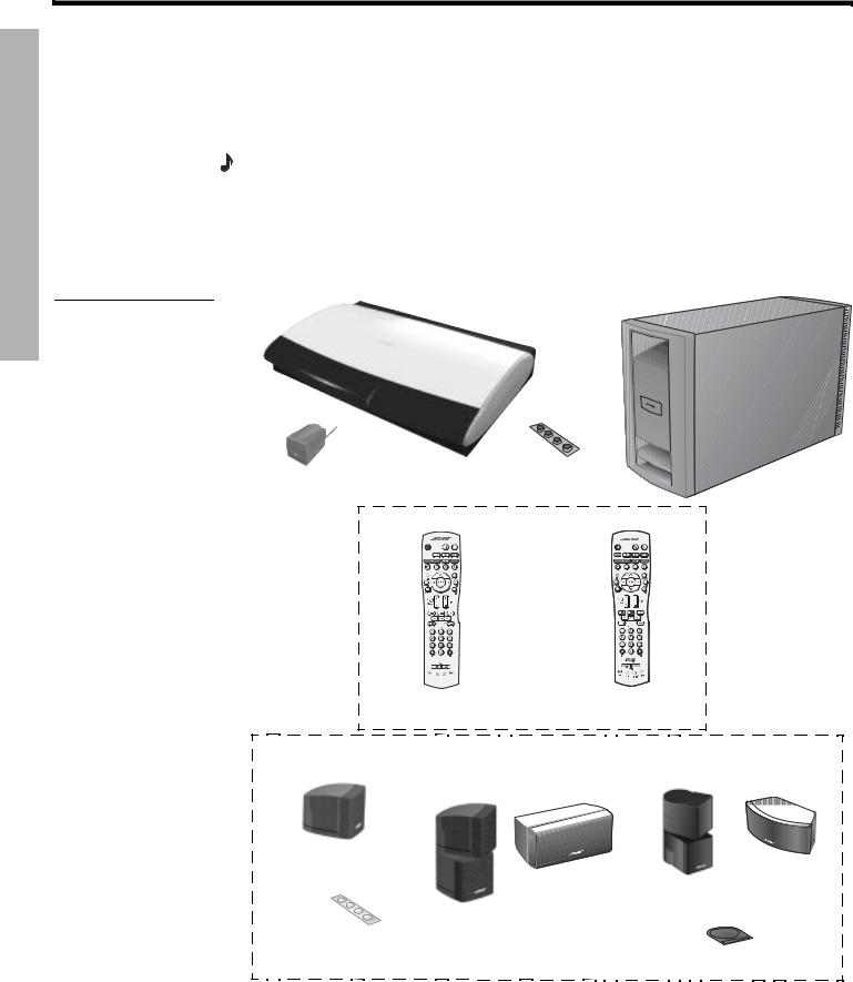
System parts
Verify that your system includes the following main parts (Figure 1).
Figure 1
Media center |
Acoustimass module |
System parts |
|
|
®® |
|
Media center |
Rubber feet |
|
for Acoustimass module |
||
power supply |
||
|
||
|
Remote control (1) |
or
For LIFESTYLE® |
For LIFESTYLE® |
18, 28, & 35 Series II systems |
38 & 48 systems |
LIFESTYLE® 18 |
Small speakers (5) |
||
|
|
|
|
Series II system |
LIFESTYLE |
® |
28 Series II & |
|
|
||
LIFESTYLE® 38 systems & 
5 Cube speakers
1 Center front speaker
|
4 Cube speaker |
Rubber feet |
arrays |
for cube speakers |
|
LIFESTYLE® 35 Series II &
LIFESTYLE® 48 systems
& |
1 Jewel Cube
4 Jewel Cube® horizontal center
speaker
speakers
Rubber pad
for Jewel Cube speaker
6

English |
DeutEspañolchDank |
FrançaisDeutschItliano |
NederlandsEspañol |
FrançaisSvenska |
Italiano |
Nederlands |
Svenska |
|
|
|
|
|
|
|
|
INTRODUCTION
Supplied cables and accessories
Cables needed to get your system operational are supplied. However, you may need others to complete your unique home theater setup as preferred.
 Note: Progressive scan, a feature of some TVs, requires using a component video cable, for
example. |
|
|
|
|
Figure 2 |
|
|
|
|
Supplied cables and |
|
|
|
Surround speaker cables (50 ft) |
accessories |
|
|
|
|
Audio input cable |
Front speaker cables (20 ft) |
|||
|
||||
Stereo audio cable |
|
S-Video cable |
||
|
Video cable (6 ft) |
|
|
Component video adapters |
Batteries |
ADAPTiQ |
® |
audio calibration system |
|
|
||||
|
|
|
|
|
Setup Disc 1 |
|
|
|
|
NTRODUCTIONI
ADAPTiQ system headset
Setup Disc 2
AM loop antenna

 FM antenna IR emitter cable
Media center power supply AC power cord
Mounting strip |
|
or |
|
SCART |
|
|
|
adapter |
|
|
for 220-240V |
|
|
systems only |
TV on/off sensor |
||
Acoustimass |
® |
module AC power cord |
|
||
120 VAC power cord |
230 VAC power cord |
(U.S./Canada) |
(Europe) |
120 VAC power cord |
230 VAC power cord |
|
(U.S./Canada) |
||
(Europe) |
||
|
230 VAC power cord |
240 VAC power cord |
(U.K./Singapore) |
(Australia) |
230 VAC power cord |
240 VAC power cord |
(U.K./Singapore) |
(Australia) |
115/230 VAC dual power cords (U.S./Europe)
115/230 VAC dual power cords (U.S./Europe)
Note: A box with dotted lines identifies parts that vary with different product versions or in different countries.
7
SYSTEM PLACEMENT
Svenska |
Nederlands |
Italiano |
FrançaisSvenska |
NederlandsEspañol |
FrançaisDeutschItliano |
DeutEspañolchDank |
English |
|
|
|
|
|
|
|
|
SYSTEM PLACEMENT
Positioning your media center
To select a location in your room for the media center, use the guidelines below:
•Place the media center close enough to other sound sources (TV, VCR, cable or satellite box), to allow for easy cable connections. Check the length of the audio and video cables you will use for these additional components.
 Note: Additional cables are available from your local Bose® dealer. Or, to contact Bose directly, refer to the address list provided in the carton. If you prefer, you can order cables from our website: www.bose.com.
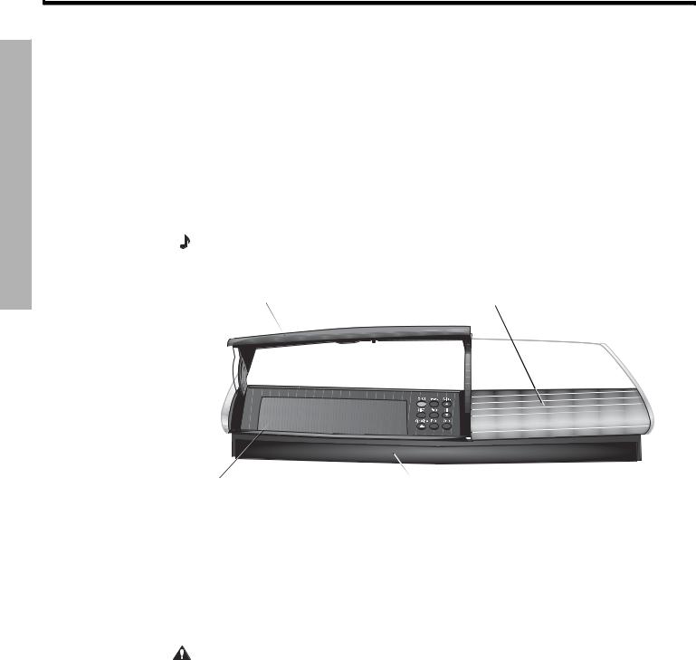
•Do not block the front of the media center. Allow enough room to lift up the front cover and open the CD/DVD tray. Also, be sure you have a clear view of the display window on the front of the media center (Figure 3).
•Place the media center within 30 feet (9.1 meters) of the Acoustimass® module ! (the length of the audio input cable).
Note: For convenience, until your system is completely installed, you may wish to keep the media center positioned for easy access to its rear connection panel.
Figure 3 |
Front door – Make sure you allow |
|
|
|
|
|
|
|
|
|
|
|
|
|
|
|
|
|
|
|
|
|
Display window – Make sure you can see |
||||||||||||||||||||||||||||||||||||
|
enough room to lift this door. |
|
|
|
|
|
|
|
|
|
|
|
|
|
|
|
|
|
|
|
|
|
this information while using your system. |
||||||||||||||||||||||||||||||||||||
Front features of the |
|||||||||||||||||||||||||||||||||||||||||||||||||||||||||||
|
|
|
|
|
|
|
|
|
|
|
|
|
|
|
|
|
|
|
|
|
|
|
|
|
|
|
|
|
|
|
|
|
|
|
|
|
|
|
|
|
|
|
|
|
|
|
|
|
|
|
|
|
|
|
|
|
|
||
media center |
|
|
|
|
|
|
|
|
|
|
|
|
|
|
|
|
|
|
|
|
|
|
|
|
|
|
|
|
|
|
|
|
|
|
|
|
|
|
|
|
|
|
|
|
|
|
|
|
|
|
|
|
|
|
|
|
|
|
|
|
|
|
|
|
|
|
|
|
|
|
|
|
|
|
|
|
|
|
|
|
|
|
|
|
|
|
|
|
|
|
|
|
|
|
|
|
|
|
|
|
|
|
|
|
|
|
|
|
|
|
|
|
|
|
|
|
|
|
|
|
|
|
|
|
|
|
|
|
|
|
|
|
|
|
|
|
|
|
|
|
|
|
|
|
|
|
|
|
|
|
|
|
|
|
|
|
|
|
|
|
|
|
|
|
|
|
|
|
|
|
|
|
|
|
|
|
|
|
|
|
|
|
|
|
|
|
|
|
|
|
|
|
|
|
|
|
|
|
|
|
|
|
|
|
|
|
|
|
|
|
|
|
|
|
|
|
|
|
|
|
|
|
|
|
|
|
|
|
|
|
|
|
|
|
|
|
|
|
|
|
|
|
|
|
|
|
|
|
|
|
|
|
|
|
|
|
|
|
|
|
|
|
|
|
|
|
|
|
|
|
|
|
|
|
|
|
|
|
|
|
|
|
|
|
|
|
|
|
|
|
|
|
|
|
|
|
|
|
|
|
|
|
|
|
|
|
|
|
|
|
|
|
|
|
|
|
|
|
|
|
|
|
|
|
|
|
|
|
|
|
|
|
|
|
|
|
|
|
|
|
|
|
|
|
|
|
|
|
|
|
|
|
|
|
|
|
|
|
|
|
|
|
|
|
|
|
|
|
|
|
|
|
|
|
|
|
|
|
|
|
|
|
|
|
|
|
|
|
|
|
|
|
|
|
|
|
|
|
|
|
|
|
|
|
|
|
|
|
|
|
|
|
|
|
|
|
|
|
|
|
|
|
|
|
|
|
|
|
|
|
|
|
|
|
|
|
|
|
|
|
|
|
|
|
|
|
|
|
|
|
|
|
|
|
|
|
|
|
|
|
|
|
|
|
|
|
|
|
|
|
|
|
|
|
|
|
|
|
|
|
|
|
|
|
|
|
|
|
|
|
|
|
|
|
|
|
|
|
|
|
|
|
|
|
|
|
|
|
|
|
|
|
|
|
|
|
|
|
|
|
|
|
|
|
|
|
|
|
|
|
|
|
|
|
|
|
|
|
|
|
|
|
|
|
|
|
|
|
|
|
|
|
|
|
|
|
|
|
|
|
|
|
|
|
|
|
|
|
|
|
|
|
|
|
|
|
|
|
|
|
|
|
|
|
|
|
|
|
|
|
|
|
|
|
|
|
|
|
|
|
|
|
|
|
|
|
|
|
|
|
|
|
|
|
|
|
|
|
|
|
|
|
|
|
|
|
|
|
|
|
|
|
|
|
|
|
|
|
|
|
|
|
|
|
|
|
|
|
|
|
|
|
|
|
|
|
|
|
|
!
Disc tray – Make sure nothing blocks ! this CD/DVD tray as it slides open.
IR emitter – Make sure nothing impedes it from sending signals to other components in the room.
Placing the five cube speakers around your room
When you place your speakers according to the guidelines that follow, they provide the audio atmosphere of a home theater. If you like, experiment with the placement and orientation of the speakers to produce the sound most pleasing to you.
Bose offers a variety of speaker mounting accessories, including stands and wall ! brackets. For more information, or to purchase accessories, contact your local Bose ! dealer or visit www.bose.com. To contact Bose directly, refer to the address list provided in the carton.
CAUTION: Choose a stable and level surface for each speaker. Vibration can cause speakers to move, particularly on smooth surfaces like marble, glass, or highly polished wood.
8
English |
DeutEspañolchDank |
FrançaisDeutschItliano |
NederlandsEspañol |
FrançaisSvenska |
Italiano |
Nederlands |
Svenska |
|
|
|
|
|
|
|
|
SYSTEM PLACEMENT
Deciding where you want the center speaker
The center speaker sound should seem to come directly from the center of the picture. The provided cable allows it to be up to 20 feet (6.1 meters) from the Acoustimass® module.
1.Place the center speaker in an upright position, directly above or below the center of the TV screen or as close to that as possible.
2.Align the front of the speaker with the front edge of the TV screen.
CAUTION: Attach the supplied rubber feet (or pad) to its bottom surface before placing a center speaker on top of your TV. This provides stability and prevents shifting from vibration.To obtain additional rubber feet, contact Bose® Customer Service. Refer to the Bose address list included with your system.
Arranging the left and right front speakers
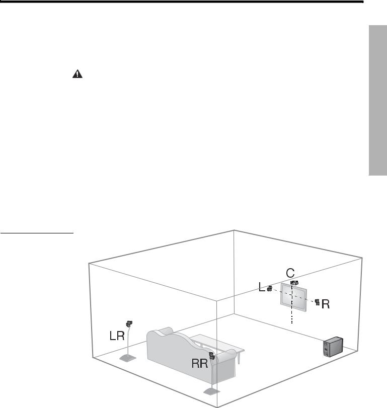
Place one speaker to the left and one to the right of the TV (Figure 4).
•Keep each speaker within 3 feet (1 meter) of the TV screen to prevent too much separation of the sound from the picture. Vary this distance to suit your room conditions and personal preference.
•If any front speakers will be in a bookcase unit, be sure to position them at the front edge ! of the shelf. Placing them farther back can change the tonal quality of the sound.
•Place the speakers up to 20 feet (6.1 meters) from the Acoustimass module, which is the length of the front speaker cables.
•Rotate the top cube of each speaker array (or the single cube) toward the wall or !
another hard surface to create reflected sound. For a view of this effect, refer to Figure 5 on page 10.
Figure 4
Recommended speaker locations
Center
Left front
Right
front
Left rear
Right
 rear
rear
LACEMENTP YSTEMS
9
SYSTEM PLACEMENT
Svenska |
Nederlands |
Italiano |
FrançaisSvenska |
NederlandsEspañol |
FrançaisDeutschItliano |
DeutEspañolchDank |
English |
|
|
|
|
|
|
|
|
SYSTEM PLACEMENT
Positions for the two rear speakers
The placement goal for rear surround speakers is to create an area of sound around the listener. By locating them in the back half of your room and directing the cubes away from the listeners, you prevent them from pinpointing the exact location of the sound source, which is ideal.
The surround speaker cables allow for up to 50 feet (15.2 meters) from the Acoustimass® module.
1.Place the speakers at ear height (when seated) or higher, if possible. The longer the path from speakers to ears, the better.
2.Adjust one cube of each speaker to reflect sound off one or more surfaces.
Choosing a location for the Acoustimass! module
While choosing the best place in your room (Figure 4 on page 9), try to keep the module:
•Along the same wall as the TV or at the same end of the room as the front speakers.
•Within the reach of:
•The media center, using the 30-ft (9.1 m) audio input cable.
•The front and center speakers, using the three 20-ft (6.1 m) speaker cables, and ! the two rear speakers using the 50-ft (15 m) speaker cables.
•An AC power (mains) outlet.
•At least 18 inches (45 centimeters) from the TV to avoid magnetically interfering with the TV image. Move it farther away if you still notice interference.
•Positioned with its grille (with a Bose® logo) facing into the room or perpendicular to the closest wall. This prevents the wall from blocking sound output or boosting the bass.
•Off-center between two walls or between a floor and ceiling.
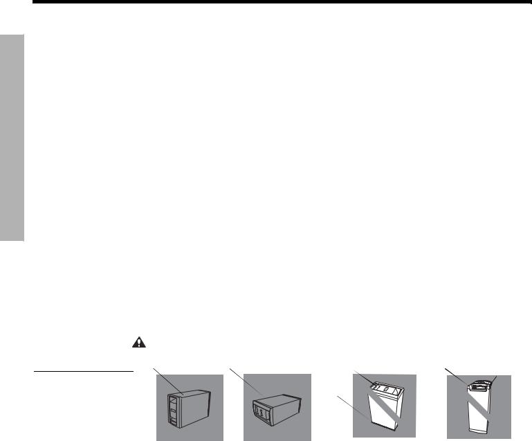
•Set on its side, top, or bottom, but NOT standing on either end (Figure 5).
CAUTION: Do not block the ventilation slots on the module.
Figure 5
Proper and improper positioning of an Acoustimass module
Top surface |
Side surface |
Front end |
Back end |
Ventilation |
|
|
|
|
openings |
Ventilation
openings
BEST |
ALTERNATE |
DO NOT |
DO NOT |
|
stand the module |
stand the module on |
|||
For best ventilation, |
Place the module |
|||
on its slightly curved |
its front grille end. The |
|||
stand the module on |
on one of its two |
|||
back end, which can |
weight of the module |
|||
its bottom surface, |
broad sides. |
|||
as shown, left. |
|
cause it to tip over. |
can damage the grille. |
•Under a table or behind a cabinet, for convenience. However, not where furniture or drapes block any openings on the module.
•With four self-adhesive rubber feet attached to the surface that touches the floor, for added stability and protection from scratches.
•Where it will not expose electronic media like tapes to its magnetic field for long periods.
10
English |
DeutEspañolchDank |
FrançaisDeutschItliano |
NederlandsEspañol |
FrançaisSvenska |
Italiano |
Nederlands |
Svenska |
|
|
|
|
|
|
|
|
SYSTEM PLACEMENT
Hearing the results of proper placement
Figure 6
Results of proper Jewel Cube® or cube speaker array placement
Figure 7
Results of proper single cube speaker placement
Placing your speakers properly is the first step to getting the full, rich, Bose® quality sound this system is designed to provide (Figure 6).
Center |
|
|
|
(C) |
Right front |
Acoustimass® |
|
Left front |
module |
||
(L) |
(R) |
||
|
|||
Left rear (LR) |
Right rear (RR) |
|
Center |
|
|
Left front (C) |
Right front |
|
(L) |
(R) |
Acoustimass |
|
|
module
LACEMENTP YSTEMS
Left rear (LR) |
Right rear (RR) |
For further validation of your setup you can rely on the two discs provided with the system. Disc 1 helps verify placement of the speakers, while Disc 2 walks you through use of the ADAPTiQ® audio calibration system. Its custom equalization adjusts the audio to compensate for room furnishings, speaker placement, and the location of listeners in your room.
11

BASIC SYSTEM CONNECTIONS
Svenska |
Nederlands |
Italiano |
FrançaisSvenska |
NederlandsEspañol |
FrançaisDeutschItliano |
DeutEspañolchDank |
English |
|
|
|
|
|
|
|
|
BASIC SYSTEM CONNECTIONS
Connecting speaker cables to the module
Your LIFESTYLE® DVD system includes five small speakers. The type of speakers in your ! system determines how the supplied cables connect to them.
•For Jewel Cube® speakers, follow the instructions below.
•For single cube or cube array speakers, follow the instructions on page 13.
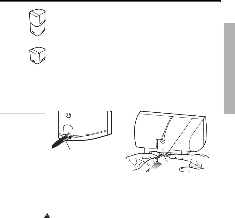
Connecting the Jewel Cube® speakers
The supplied cables feature a plug-in connector that ensures proper polarity (+ to + and !
– to –) connections.
• Use the supplied 20-ft (6.1 m) cables for the three front speakers.
Jewel Cube speaker
•Use the supplied 50-ft (15.2 m) cables for the speakers at the rear of your room. !
After running these cables to the rear of your room, you can unzip them by simply pulling them apart. This makes it is easy to reach each of the rear speakers.
To make the connections:
Jewel Cube 1. Notice the marking on each cable plug and match it to the speaker in that location:
horizontal center speaker
• Front speaker cable plugs have L (left), R (right), and C (center) markings.
• Rear speaker cable plugs have LR (left rear) and RR (right rear) markings.
2. Orient the plug with its small knob up, so the plug slips easily into a notch on top of the jack on the back of each speaker (Figure 8).
3. Insert the plug fully into the jack on the rear of its respective speaker.!
For example, the plug marked L connects to the speaker at the left front of your room.
Figure 8
Knob up
Plug-in connections to these speakers
R, L, |
C |
|
RR, or LR |
||
Cable plug |
4.Follow the instructions on page 13 to connect each cable to the corresponding jack on the Acoustimass® module.
12
English |
DeutEspañolchDank |
FrançaisDeutschItliano |
NederlandsEspañol |
FrançaisSvenska |
Italiano |
Nederlands |
Svenska |
|
|
|
|
|
|
|
|
BASIC SYSTEM CONNECTIONS
Connecting single cube or cube array speakers
These speakers feature red and white connection terminals on the back of each speaker. Be sure to match the red-collared wire to the red terminal, to maintain positive-to-positive (+ to +) connections.
Cube array speaker • Use the supplied 20-ft (6.1 m) cables for the three front speakers.
•Use the supplied 50-ft (15.2 m) cables for the speakers at the rear of your room. !
After running these cables to the rear of your room, you can pull them apart to reach each of the rear speakers.
• To make the connections:
Single cube speaker 1. Notice a label on each red-collared wire that matches it to the proper speaker (Figure 9a).!
• L for the speaker at the left front |
• |
LR for the speaker at the left rear |
|
• |
C for the speaker at the center front |
• |
RR for the speaker at the right rear |
• |
R for the speaker at the right front |
|
|
Figure 9
Making the connection to
(a) a single cube or cube array speaker and (b) to a center speaker (not provided in all systems)
2.Press the terminal tab to insert each wire into the proper jack (Figure 9b).
(a) |
(b) |
Terminal tab |
L, R, C, LR, or RR
Red terminal
3.Follow the instructions below to connect each cable to the corresponding jack on the Acoustimass® module.
Connecting the speakers to the module
You may find it convenient to temporarily turn the module upside down while making these connections. Then, be sure to place the module on its side or bottom surface when the ! connections are completed.
CAUTION: Before you make these connections, be sure that the media center and the Acoustimass module are NOT yet connected to an AC (mains) power outlet.
To make these connections:
1.Use the colors and labels on the RCA connectors at the free end of each speaker cable as guides in connecting to the module. For a color reference, you may want to use the Quick Setup Guide provided in the carton.
ONNECTIONSC YSTEMS ASICB
13
BASIC SYSTEM CONNECTIONS
Svenska |
Nederlands |
Italiano |
FrançaisSvenska |
NederlandsEspañol |
FrançaisDeutschItliano |
DeutEspañolchDank |
English |
|
|
|
|
|
|
|
|
BASIC SYSTEM CONNECTIONS
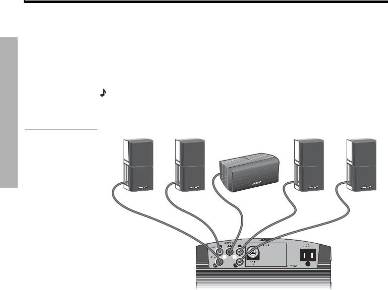
2.Connect the front speaker cables as follows (Figure 10):
•White connector labeled L goes into the white jack labeled Front L.
•Light blue connector labeled R goes into the light blue jack labeled Front R.
•Brown connector labeled C goes into the brown jack labeled Front C.
3.Connect the rear speaker cables as follows:
•Light green connector labeled LR goes into the light green jack labeled Rear LR.
•Purple connector labeled RR goes into the purple jack labeled Rear RR.
Note: To lengthen speaker cables, as needed, you can splice in 18-gauge or thicker cord (connecting + to + and – to –). Or, you can order heavy-duty speaker extension cable from Bose. To contact Bose directly, refer to the address list provided in the carton.
Figure 10 |
|
Speakers placed around the room |
|
||
Matching connector |
Right Rear |
Right Front |
Center Front |
Left Front |
Left Rear |
markings to those on the |
|
|
|
|
|
Acoustimass® module jacks |
|
|
|
|
|
R |
C |
L |
LR |
|
|||
RR |
|
|
|
|
|
|
Acoustimass module connector panel
14
 Loading...