


ESP-88C
Table of contents
 Loading...
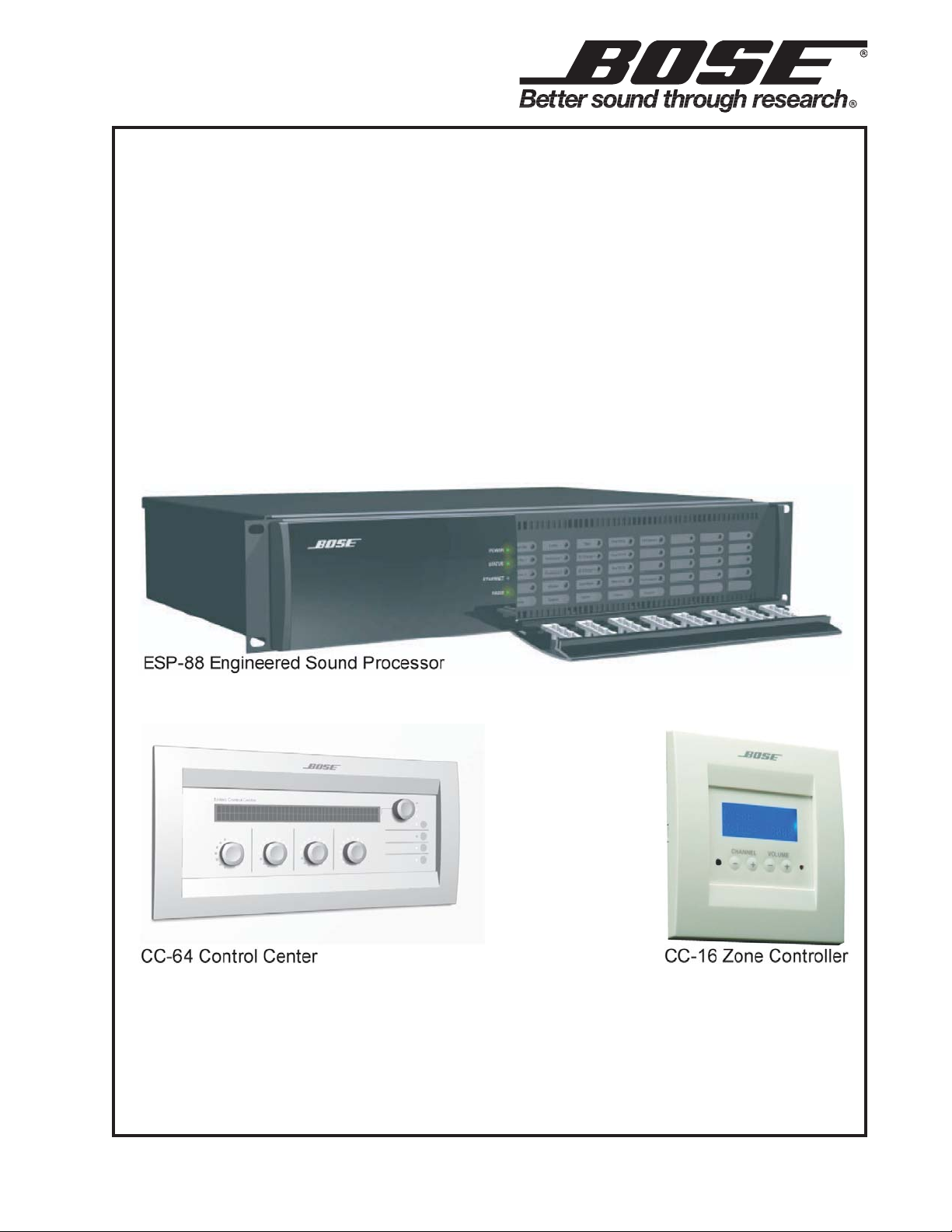
ControlSpace® ESP-88C and ESP-00
Engineered Sound Processors,
CC-16 and CC-64 Controllers
(US and non-US units)
©2009 Bose Corporation
Service Manual
Reference Number 313419-SM Rev. 01
Electronic Copy Only

CONTENTS
Safety Information.....................................................................................................................................3
Warranty.....................................................................................................................................................3
Product Description...............................................................................................................................4-7
Specifications .......................................................................................................................................8-10
Electrostatic Discharge Sensitive (ESDS) Device Handling................................................................11
Part List Notes......................................................................................................................................... 11
Packaging Part List, ControlSpace
Figure 1. ESP-88C/ESP-00 Chassis Packing View ................................................................................12
Packaging Part List, ControlSpace CC-16 Controller ..........................................................................13
Figure 2. CC-16 Controller Packing View ...............................................................................................13
Packaging Part List, ControlSpace CC-64 Controller ..........................................................................14
Figure 3. CC-64 Controller Packing View ...............................................................................................14
Main Part List, ControlSpace ESP-88C/ESP-00 Chassis (see Figure 4) ........................................15-16
Figure 4. ControlSpace ESP-88C/ESP-00 Chassis Exploded V iew .......................................................16
Main Part List, ControlSpace CC-16 Controller....................................................................................17
Figure 5. ControlSpace CC-16 Controller Exploded V iew.......................................................................17
Main Part List, ControlSpace CC-64 Controller....................................................................................18
Figure 6. ControlSpace CC-64 Controller Exploded V iew.......................................................................18
Electrical Part List..............................................................................................................................19-67
ESP-88C and ESP-00 Chassis Motherboard PCB Assembly..........................................................19-26
ESP-88C Chassis 4x4 Series II PCB Assembly................................................................................27-45
ESP-88 Digital Signal Processor (DSP) PCB Assembly..................................................................46-59
ESP-88 Output PCB Assembly...............................................................................................................60
ESP-88 LED PCB Assembly ................................................................................................................... 60
CC-64 Control Center.........................................................................................................................61-65
CC-16 Zone Controller .......................................................................................................................66-67
Disassembly Procedures...................................................................................................................68-70
ESP88C and ESP-00 Front Panel Indicators and Features ................................................................. 71
ESP88C and ESP-00 Rear Panel Controls and Connections .........................................................72-73
T est Procedures ...............................................................................................................................74-100
Figure 7. ATS-2, ESP-88C/ESP-00 and AuBit Switchbox Test Setup Diagram ......................................76
Figure 8. Astec LPT83 Switch Mode Power Supply..............................................................................101
DC Power Supply +5V Adjustment Procedures ................................................................. 102-103
Troubleshooting............................................................................................................................104
Service Manual Revision History.................................................................................................105
®
ESP-88C and ESP-00 Chassis...................................................12
2
SAFETY INFORMATION
1. Parts that have special safety characteristics are identified by the symbol on schematics
or by special notes on the parts list. Use only replacement parts that have critical characteristics
recommended by the manufacturer.
2. Make leakage current or resistance measurements to determine that exposed parts are
acceptably insulated from the supply circuit before returning the unit to the customer.
Use the following checks to perform these measurements:
A. Leakage Current Hot Check-With the unit completely reassembled, plug the AC line cord
directly into a 120V AC outlet. (Do not use an isolation transformer during this test.) Use a
leakage current tester or a metering system that complies with American National Standards
Institute (ANSI) C101.1 "Leakage Current for Appliances" and Underwriters Laboratories (UL)
UL6500 / UL60065 / IEC 60065 paragraph 9.1.1. With the unit AC switch first in the ON position
and then in OFF position, measure from a known earth ground (metal waterpipe, conduit, etc.)
to all exposed metal parts of the unit (antennas, handle bracket, metal cabinet, screwheads,
metallic overlays, control shafts, etc.), especially any exposed metal parts that offer an electrical
return path to the chassis. Any current measured must not exceed 0.5 milliamp. Reverse the
unit power cord plug in the outlet and repeat test. ANY MEASUREMENTS NOT WITHIN THE
LIMITS SPECIFIED HEREIN INDICATE A POTENTIAL SHOCK HAZARD THAT MUST BE
ELIMINATED BEFORE RETURNING THE UNIT TO THE CUSTOMER.
B. Insulation Resistance Test Cold Check-(1) Unplug the power supply and connect a jumper
wire between the two prongs of the plug. (2) Turn on the power switch of the unit. (3) Measure
the resistance with an ohmmeter between the jumpered AC plug and each exposed metallic
cabinet part on the unit. When testing 3 wire products, the resistance measured to the product
enclosure should be between 2 and infinite MOhms. Also, the resistance measured to exposed
input/output connectors should be between 4 and infinite MOhms. When testing 2 wire products, the resistance measured to exposed input/output connectors should be between 4 and
infinite MOhms. If it is not within the limits specified, there is the possibility of a shock hazard,
and the unit must be repaired and rechecked before it is returned to the customer.
CAUTION: The Bose® ControlSpace® ESP-88C and ESP-00 Systems, CC-16 and CC-64
Controllers contains no user-serviceable parts. To prevent warranty infractions, refer
servicing to warranty service stations or factory service.
PROPRIETARY INFORMATION
THIS DOCUMENT CONTAINS PROPRIETARY INFORMATION OF
BOSE CORPORATION WHICH IS BEING FURNISHED ONLY FOR
THE PURPOSE OF SERVICING THE IDENTIFIED BOSE PRODUCT
BY AN AUTHORIZED BOSE SERVICE CENTER OR OWNER OF
THE BOSE PRODUCT, AND SHALL NOT BE REPRODUCED OR
USED FOR ANY OTHER PURPOSE.
WARRANTY
The Bose ControlSpace ESP-88C and ESP-00 Systems and CC-16 and CC-64 Controllers are
covered by a limited 5-year transferable warranty.
3

PRODUCT DESCRIPTION
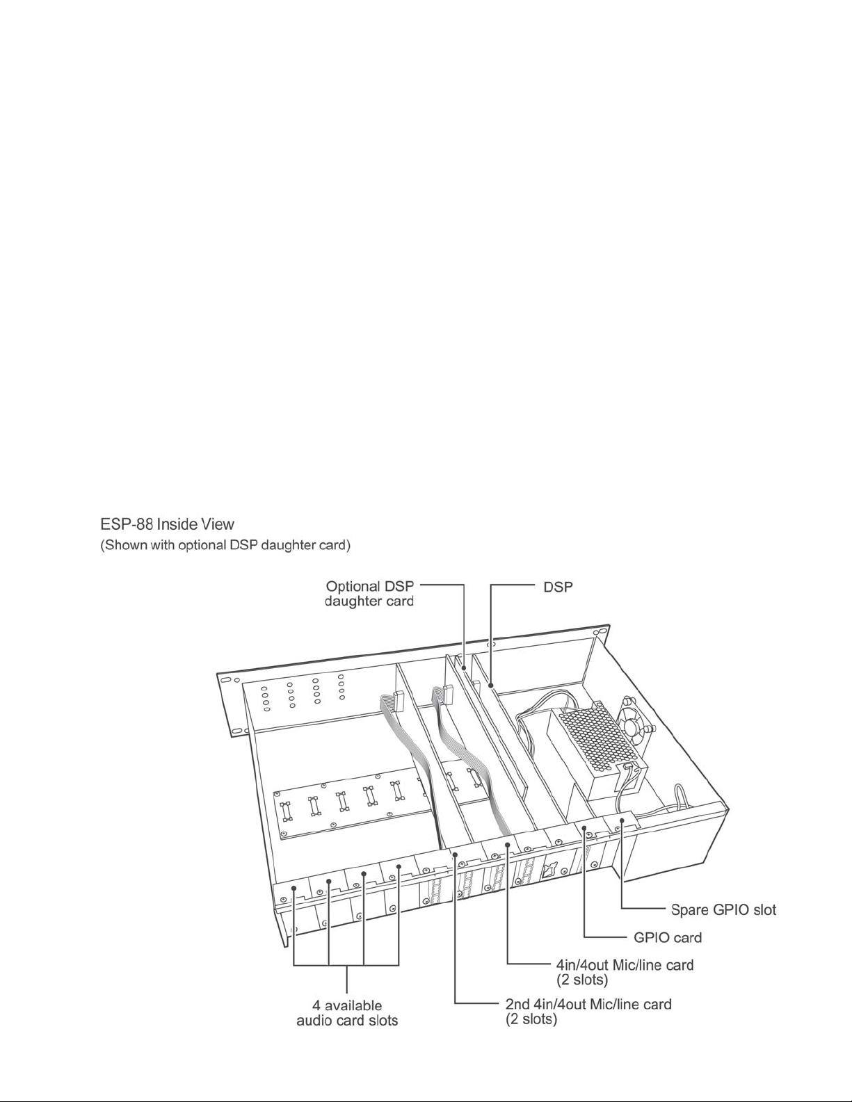
ESP-88 Chassis Overview:
The Bose
expandable and high quality audio signal processors for engineered sound applications such as
churches, theaters, auditoriums, and sports venues.
The ESP-88C includes eight inputs (microphone or line-level selectable) and eight line level
outputs. Four available audio slots allow the addition of up to 16 more analog audio channels –
inputs, outputs or a combination – or up to 32 more digital audio channels (AES3) as inputs,
outputs or a combination.
For large applications, multiple chassis can be used per system. Multiple choices of user controllers are available to provide end-users with simple, easy-to-use control of their ControlSpace
system.
The Bose ControlSpace Designer software is used to design systems and configure the
chassis and user controllers. The software runs on a PC and communicates to the chassis over
Ethernet.
Features and functions:
• Expandable and flexible cardframe architecture
• Eight mic/line analog audio input channels
• Eight line level analog audio output channels
• Four open audio expansion slots allow up to 32 analog audio channels total in a 2U chassis
• DSP expansion slot allows DSP processing power and delay times to increase fourfold
• Eight general purpose control inputs and eight general purpose control outputs (GPIO)
• GPIO expansion slot allows up to 16 control inputs and 16 control outputs
• All audio input and input channels feature tricolor level LEDs
• Design, control and configuration via PC based software and Ethernet connection.
• Large set of signal processing modules including: Bose speaker EQs, Bose crossovers,
graphic and parametric EQs, routers, delays, matrix mixers, signal generators,
meters, compressors/Limiters, duckers, automatic gain controls, gate and source selectors.
®
ControlSpace® ESP-88C and ESP-00 engineered sound processors are flexible,
Modularity and Expansion
Flexible Architecture
The ESP-88C and ESP-00 employ a flexible, modular architecture. This flexible architecture
provides two levels of DSP performance – up to 32 general-purpose I/O and up to 64 digital
audio channels – or up to 32 analog audio channels.
The base model ESP-88C, includes a DSP card, two 4x4 Mic/Line cards and one GPIO card. In
this configuration, four audio and one GPIO slot are available for expansion. The ESP-00 omits
the two 4x4 Mic/Line cards.
Four types of optional cards are available: DSP expansion, GPIO, Audio and Surround Sound.
DSP expansion card, PC037535 - Daughter card for main DSP card. Increases performance by
300%. One card can be added to an ESP-88.
GPIO card, PC 041768
Fits in one of the two GPIO slots. Eight control inputs and eight control outputs. One GPIO card
can be added to an ESP-88.
4
PRODUCT DESCRIPTION
ESP-88 Chassis Overview (continued):
Optional Cards
Audio Cards:
4x4 mic/line card Series II, PC 041915 (not included with the ESP-00)
Occupies two audio slots. Four microphone or line level inputs (software selectable), and four
line level outputs. The ESP-88C includes two 4x4 Mic/line cards. Two 4x4 cards can be added.
EDR line level output card, PC 041763
Occupies one audio slot. Four highest-quality, line level outputs.
EDR line level input card, PC 041764
Occupies one audio slot. Four highest-quality, line level inputs.
AES3 output card, PC 041766
Occupies one audio slot. Eight AES3 outputs (two per output connector).
AES3 Input card, PC 041765
Occupies one audio slot. Eight AES3 inputs (two per input connector).
Surround Sound card, Bose® part number 302210
Occupies one audio slot. One optical and one coaxial digital audio inputs.
5

CC-16 Zone Controller
PRODUCT DESCRIPTION
The Bose
mounted device designed to provide end-user control of ControlSpace
systems. Custom programming allows the CC-16 to control a variety of
the system elements, from switching audio sources to selecting
“scenes” or system configurations. The CC-16 features a bitmap LCD
and four buttons for displaying and controlling the system settings.
The CC-16 connects to the ControlSpace Engineered Sound Processor (ESP-88) at the RS-485 port. Up to fifteen CC-16 units can be
used per each ESP-88 to provide localized control of the system. The
maximum distance from ESP-88 to CC-16 is 2000 feet. As a networked device, remote reprogramming is possible at any time.
Features and Functions
• 122 x 32 pixel backlit blue LCD
• LCD displays volume level and source/scene/preset setting
• Select up/down buttons for selecting sources or scenes
• Volume up/down buttons for controlling one or more gain controls
• IR receiver (for IR remote controls)
• RS-485 network supports up to fifteen CC-16 units per ESP-88
• DIP-switch for specifying network address and termination
• Universal mounting bracket
• UL and CE listed
®
ControlSpace® CC-16 zone controller is an elegant wall-
CC-64 Control Center
The Bose ControlSpace CC-64 control center is an
elegant, programmable, networked controller that
provides users with a simple and logical interface to
their ControlSpace system. Because the controller is
completely programmable, you can customize the
ControlSpace system, making only certain controls
available, and simplifying user interaction with the
system.
The CC-64 provides four rotary encoders with
circular LED arrays for a userfriendly method of
managing gain settings or scene selections. A fifth encoder provides control over programmed
“scenes” or presets. Four bank switch buttons redefine the four Gain/Selector control knobs,
providing quick access for up to 16 system gain controls or selectors. A large, 2-line by 40character backlit LCD provides the user with the names of the system elements they are controlling (gains, presets, etc.).
Using custom programming, the CC-64 can manage a variety of system elements, including
audio sources, scene selection settings, and specific system configurations. Each gain control
can be ganged so that a single control can be mapped to as many as sixteen system gains. The
CC-64 also supports a “custom mode” – intended for installers, not end users – in which any
parameter in the system can be viewed and changed using the LCD display and control knobs.
6

PRODUCT DESCRIPTION
CC-64 Control Center (continued)
The CC-64 is a 10Base-T Ethernet device. Up to sixteen CC-64s can be used per
ControlSpace
Features
• 2-line by 40-character backlit LCD
• Sixteen Gain/Selector controls (four banks of four)
- Four rotary encoders for changing the gain level or selecting scenes/sources
- Each encoder includes a 15-segment LED array for indicating the control’s current level or
state
- The encoders feature push buttons for muting gain controls or making selections
- Ten character descriptions of the gain controls appear on the LCD above the encoder
• Four bank switch buttons with label area
• Lock function in software prevents local changes
• 10Base-T Ethernet network based
• Sixteen CC-64s per ControlSpace system
• Power over Ethernet cable or separate cable
• LEDs for status, link and network transmit/receive
• Fits standard 5-gang electrical box
• UL6500 listed and CE approved
Functions
1. LCD
2. Preset/Scene selector
- Rotate to view presets. Push to select.
- Push and hold for 5 seconds to enter Custom mode.
3. Network link indicator
4. Network receive indicator
5. Network transmit indicator
6. Bank select buttons (4). Press to select one of four bank controls
7. Bank select indicators (4). Indicates the currently selected bank
8. Bank select label area. 1.25" (31.75 mm) x .35" (9 mm) area for custom labels.
- Accepts standard 3/8" (9 mm) label stock.
9. Gain/Selector control knob. Rotary encoder (no stops). Push to mute.
10. Gain/Selector level indicators (15 levels/selections)
®
system.
7

SPECIFICATIONS
Inputs
T ype: 8 analog, electronically balanced, microphone/line level
(software selectable)
Connectors: Phoenix/Euroblock 2-piece, 3-pin
Nominal Input Level: +4dBu/-10dBu/-20dBu/-38dBu/-44dBu/-50dBu/-60dBu
Frequency Response: 20 to 20kHz (+0.5dB / -2.0dB) at +4dBu nominal input level
Input Impedance: 2.4k ohm @ 1kHz (with or without phantom power active)
Maximum Input Level: +24dBu @ +4dBu nominal input power
Equivalent Input Noise: -115dB at -60dBu nominal input level (A-weighted/20-20kHz)
Phantom Power: +15V nominal, selectable per input
THD+N: 0.01% at +4dBu nominal input and output level
(A-weighted/20-20kHz)
Digital Resolution: 24-bit
Outputs
T ype: 8 analog, electronically balanced
Connectors: Phoenix/Euroblock 2-piece, 3-pin
Nominal Output Level: +4dBu
Output Impedance: 200 Ohms (600 Ohm load expected)
Frequency Response: 20 to 20kHz (+0.5dB/-2.0dB) at +4dBu nominal output level
Maximum Output Level: +24dBu at +4dBu nominal output level
Digital Resolution: 24-bit
Signal to Noise Ratio (SNR): 80dB at +4dBu nominal output level (A-weighted/20-20kHz)
Residual Output Noise: -110dBu at output muted (A-weighted/20-20kHz)
THD+N: 0.01% at +4dBu nominal input and output level
(A-weighted/20-20kHz)
Crosstalk: < -90dB at +4dBu nominal input and output level at 1kHz
8

SPECIFICATIONS
Signal Processing
T ype: 32-bit floating-point digital signal processor(s)
Clock Speed: 200MHz
Maximum Calculation: 1600 MIPS/1200 MFLOPS
(6400 MIPS/4800 MFLOPS with DSP option card)
Delay Memory: 16MByte/72s (maximum)
(64MByte/288s maximum with DSP option card)
Audio Latency: 610us (analog in to analog out) (860us with DSP option card)
Sampling Rate: 48kHz
Control Inputs
T ype: 8 analog or digital inputs, 5.1k ohms internal pull-up resistor
to 5V
Connectors: Phoenix/Euroblock 2-piece, 9-pin 3.81mm pitch
Analog Input: 0V to 3.3V (max 5V; suitable for 10k ohm variable resistor)
Digital Input Voltage Range: 0V to 3.3V (threshold voltage = 1.6V; internal 5.1k ohms pulled
up to 5V)
Control Outputs
T ype: 8 digital outputs, 10k ohms internal pull-up resistors to 5V
Connectors: Phoenix/Euroblock 2-piece, 9-pin 3.81mm pitch
Output Voltage: 0V to 5V open collector
Output Current: 0.5mA (source)/10mA max (sink)
Communication Ports
LAN: 10Base-T (RJ-45)
RS-232C: D-sub 9 pin, male; DTE
RS-485: Phoenix/Euroblock 2-piece, 3-pin
Indicators
Status: Power/Status/Ethernet/Serial (RS232C + RS485)
Audio: Signal (Present/Normal/Clip) for each audio input and output
9
SPECIFICATIONS
Expansion Slots
Audio I/O: 8 slots (4 slots occupied)
Control I/O: 2 slots (1 slot occupied) Max 16 inputs/16 outputs
DSP: 1 slot
Audio Channels
Analog: 32 max (all slots full)
Digital (AES3): 64 (all slots full)
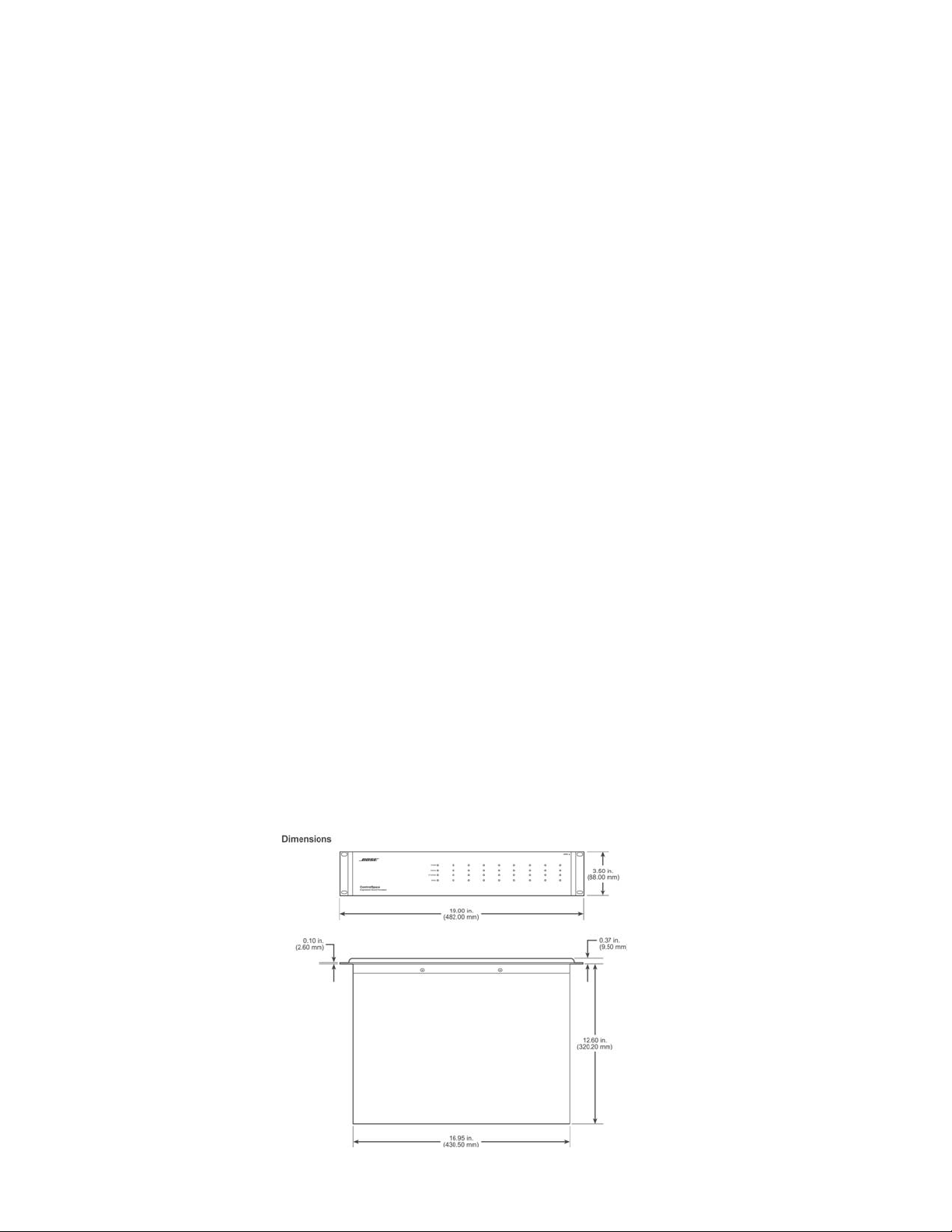
Mechanical
Dimensions: 18.9”W x 3.5”H x 12.6”D (482 x 88 x 320mm)
Weight: 14 lb. (5.3 kg)
Electrical
Mains Voltage: 85 - 264 VAC 50/60 Hz with PFC
Power Consumption: < 35VA
Maximum Power < 70VA (at <35 degrees C ambient)
Consumption:
Environmental
Operating Temperature: < 50 degrees C at less than 35VA / < 40 degrees C at
less than 70VA
Humidity: 80% relative humidity (without condensation)
10

ELECTROSTATIC DISCHARGE SENSITIVE (ESDS)
DEVICE HANDLING
This unit contains ESDS devices. We recommend the following precautions when repairing,
replacing or transporting ESDS devices:
• Perform work at an electrically grounded work station.
• Wear wrist straps that connect to the station or heel straps that connect to conductive
floor mats.
• Avoid touching the leads or contacts of ESDS devices or PC boards even if properly
grounded. Handle boards by the edges only.
• Transport or store ESDS devices in ESD protective bags, bins, or totes. Do not insert
unprotected devices into materials such as plastic, polystyrene foam, clear plastic bags,
bubble wrap or plastic trays.
PART LIST NOTES
1. This part is not normally available from Customer Service. Approval from the Field Service
Manager is required before ordering.
2. The individual parts located on the PCBs are listed in the Electrical Part List.
3. This part is critical for safety purposes. Failure to use a substitute replacement with the
same safety characteristics as the recommended replacement part might create shock, fire
and/or other hazards.
4. This part is referenced for informational purposes only. It is not stocked as a repair part. Refer
to the next higher assembly for a replacement part.
11
Item
Description Qty. Part Number Note
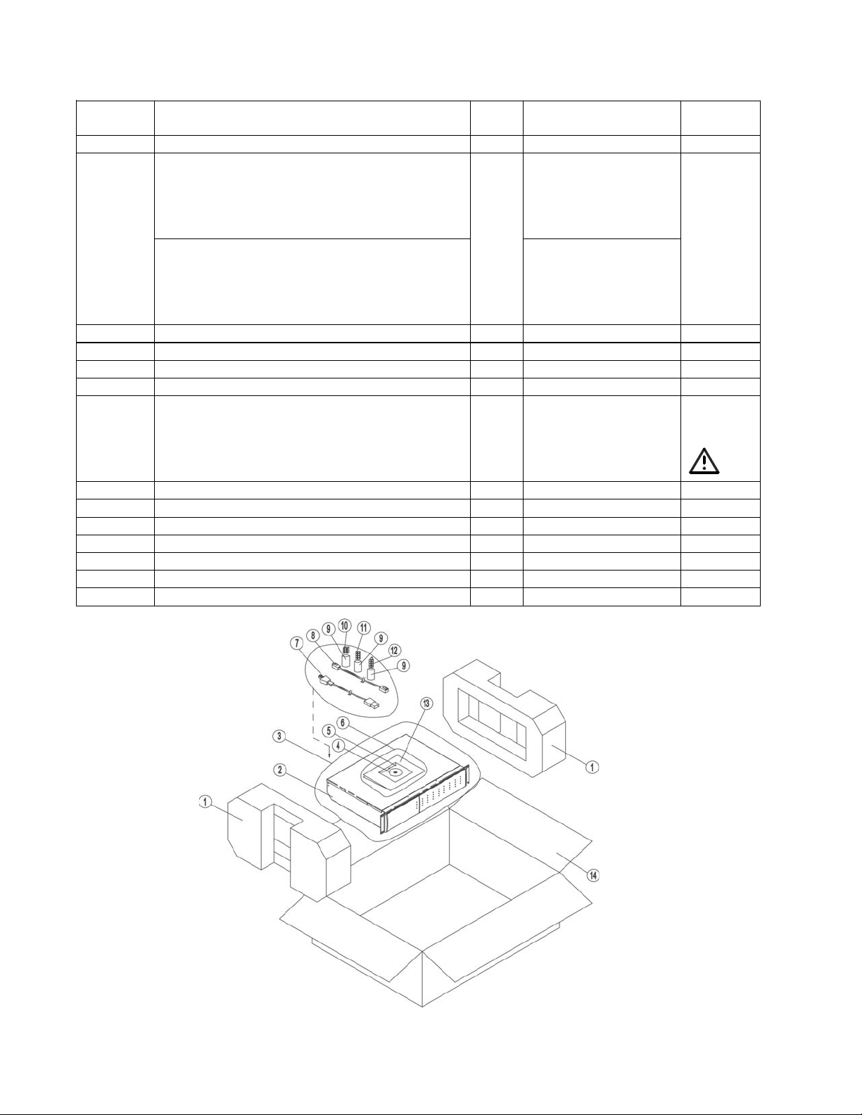
PACKAGING PART LIST
ControlSpace® ESP-88C and ESP-00 Chassis
Number
1 EPE FOAM 2 312474
2 ESP-88C Chassis, US/CAN
ESP-88C Chassis, EURO
ESP-88C Chassis, JAPAN
ESP-88C Chassis, UK
ESP-88C Chassis, AUS
ESP-00 Chassis, US/CAN
ESP-00 Chassis, EURO
ESP-00 Chassis, JAPA N
ESP-00 Chassis, UK
ESP-00 Chassis, AUS
3 POLYBAG, L550xW600MM 1 - 4
4 CONTROLSPACE CD KIT 1 317462-0010 4
5 CD SLEEVE 1 - 4
6 POLYBAG, L300xW150MM 1 - 4
7 POWER CORD, 120V, U S/C AN
POWER CORD, 220V, EURO
POWER CORD, 100V, JAPA N
POWER CORD, 240V, UK
POWER CORD, 240V, AUS
8 CAT-5 ETHERNET CABL E 1 - 4
9 POLYBAG, 100x60MM 3 - 4
10 TERMINAL BLOCK, 9 POS 2 305532
11 TERM BLOCK, PLUG, ORANGE 8 305535
12 TERM BLOCK, PLUG, GREE N 9 305536
13 USER MANUAL 1 275800
14 CARTON 1 275797
1 313419-0010
313419-0020
313419-0030
313419-0040
313419-0050
315228-0010
315228-0020
315228-0030
315228-0040
315228-0050
1 315416-0010
315420-0010
315417-0010
315418-0010
315419-0010
3
Figure 1. ESP-88C/ESP-00 Chassis Packing View
12
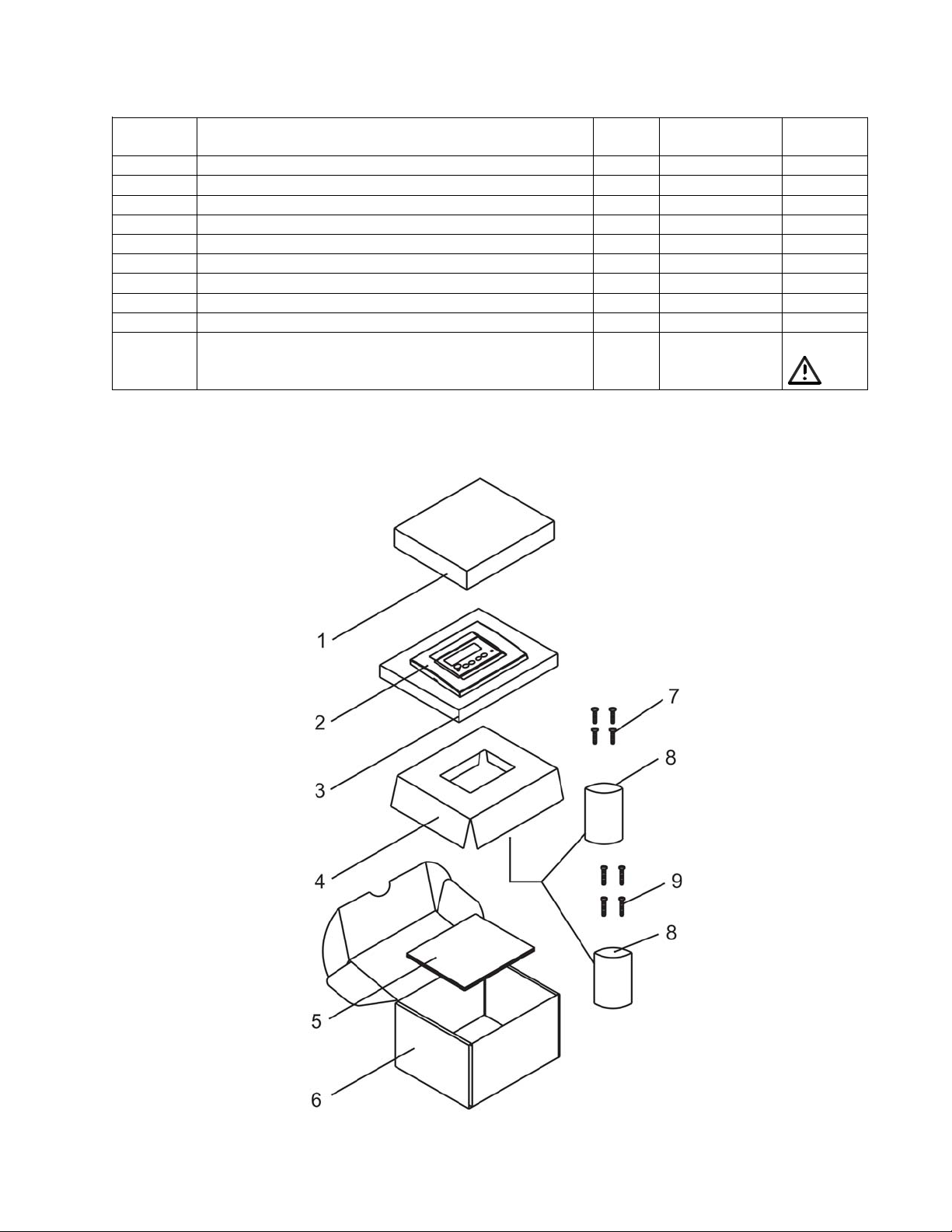
PACKAGING PART LIST
Item
Description Qty. Part Number Note
ControlSpace® CC-16 Controller
Number
1 Foam, White EPE 1 - 4
2 CC-16 Controller 1 041761 2
3 Anti-static bag, 150 x 180 x 0.03MM 1 - 4
4 Paper Tray 1 - 4
5 In st all at io n Man ual, English Languag e 1 285042
6 White box 1 - 4
7 Screw , #6-32x0.7", Phillips, ZI NC (US/Japan) 4 - 4
8 Bag, Poly, 40 x 60MM 2 - 4
9 Screw , M4. 0x18, Phillips, ZINC (Europe) 4 - 4
- Power Supply, 15VDC, 5W, 100-240VAC I nput
(not packaged w/CC-16)
1 041762 3
Figure 2. CC-16 Controller Packing View
13
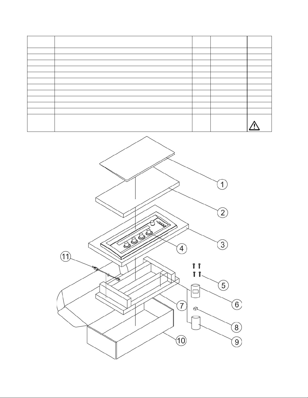
PACKAGING PART LIST
ControlSpace® CC-64 Controller
Item
Number
1 Install Guide, CC-64 1 285041
2 EPE Foam, 330X180X15MM 1 - 4
3 Bag, PE, Anti-Static, 330X180X0.03MM 1 - 4
4 CC-64 Controller 1 041760 2
5 Screw, US, MSF, #6-32X0.7, MS, ZN-WH 4 - 4
6 Bag, Poly, 40X60MM 1 - 4
7 Tray, Foam, EPE, 330x180x45MM 1 - 4
8 Terminal Block, 2P, P5.08, 2ESDV-02P 1 - 4
9 Bag, Poly, 100X60MM 1 - 4
10 White Box, W9B 1 - 4
11 Computer UTP LAN Cable, 2M, CAT 5 1 - 4
- Power Supply, 15VDC, 5W, 100-240VAC Input
(not packaged w/CC-64)
Description Qty. Part Number Note
1 041762 3
Figure 3. CC-64 Controller Packing View
14
Item
Description Qty. Part Number
Note
MAIN PART LIST
ControlSpace® ESP-88C/ESP-00 Chassis (see Figure 4)
Number
1 TOP COVER 1 278505-001
2 M3x4 SCREW, MSF, MS-BK
(FOR CHASSIS/COVER)
3 M3x4 SCREW, SI, MSB, MS-BK 62 - 4
4 GIO REAR PAN EL, SECC-T1, T=1.0MM 1 278516-001
5 PANEL, REAR, BLANK, SECC-T1 T=1.0MM 5 278518-001
6 DSP REAR PANE L, SECC-T1, T=1.0MM 1 278515-001
7 4CH REAR PANEL (LINE OUTPUT) SECC-T1
8 4CH REAR PANEL (MIC/LINE INPUT) SECC-T1
9 4x4 LINE OUTPUT PCB ASSY
10 4X4 MIC/LINE SERIES II I/O PCB 2 041915 2
11 PCB FIXED STICK, ABOVE 2 278503-001
12 MOTH ERBO A RD P CB ASS Y 1 318934-001S
13 M3x6 SCREW, MSB, M3x6mm, MS-BK 5 - 4
14 INTERNAL TOOTH WASHER,
15 LED LENS, PMMA, MF0 01 9 278522-001
16 FRONT ENDCAP, RIGHT, PC/ABS, C2950
17 DOOR, ALUMINUM 1 278520-001
18 FRONT P ANEL, ALUM , FIXED 1 278519-001
19 FRONT ENDC AP, MID, PC/ABS, C2950
20 FRONT ENDC AP, LEFT, PC/ABS, C2950
21 FRONT P ANEL, SEC C-T1 1 278507-001
22 CHASSIS 1 278506-001
23 PCB FIXED STICK, BELOW 1 278504-001
24 SCREW , US, MSF, 4#-40x0.236, MS, BLACK 4 - 4
25 LED PCB ASSEMBLY (PART OF MIC/LINE
26 POW ER S UPPLY , ASTEC 1 318933-001S
27 M4x12 SCREW, SI, MSB, MS-BK (FOR FAN) 4 - 4
28 DC FAN, +5VDC, 60MM, F6010AP-05LCW 1 295621 3
29 M4x3 HEX NUT W/NYLON INSERT, SI, SS 4 - 4
30 DSP PCB ASSEMBLY 1 275794 2
31 GPIO PCB ASSEMBLY 1 041768 2
32 STAY, SECC-T1, T=1.0MM 1 278508-001
- DSP EXPANSION C ARD - 041769
- 8-CH DIGITAL IN EXP PCB - 041765
- 8-CH DIGITAL OUT EXP PCB - 041766
- 4-CH ANALOG IN EXP PCB
- 4-CH ANALOG OUT EXP PCB
T=1.0MM
T=1.0MM
(PART OF ITEM 10 BELOW)
OD 6.4xID3xT0.45MM
(M3x3 NU T )
(M3x2 NU T )
(M3x3 NU T )
IN/OU T MA IN P C B )
(EDR Line Level Input Card)
(EDR Line Level Output Card)
4 - 4
2 278512-003
2 278512-002
2 -
2
7 - 4
1 278521-002
1 278521-003
1 278521-001
2 - 2
3
- 041764
- 041763
15

MAIN PART LIST
Item
Description Qty. Part Number
Note
ControlSpace® ESP-88C/ESP-00 Chassis (continued)
Number
- 4-CH SDR OUTPUT PCB - 041916
- 4-CH MIC/LINE INPUT PCB - 041917
- SURROUND DECODER INPUT PCB - 302210 2
- AC POWER SWITCH, ROCKER, SPST,
125V/15A
- AC SOCKET, IEC, 250V/10A 1 - 3, 4
- Power Supply Harness, Improved, ESP-88C /
ESP-00 (used with the Astec power supply)
- Power Supply Harness, Improved, ESP-88 /
ESP-88C (used with the IPD power supply)
1 - 3, 4
1 318935-001S
1 318938-001S
3
3
Figure 4. ControlSpace ESP-88C/ESP-00 Chassis Exploded View
16

MAIN PART LIST
Item
Description Qty.
Note
ControlSpace® CC-16 Controller
Part Number
Number
1 Front plate, PC, GE, LEXAN, 241R, White 1 275432
2 Overlay, PC sheet, w/adhesive, 0.18mm 1 277488
3 Insert, plate, PC, GE, LEXAN, 241R, White 1 275434 4
4 LCD PCB Assembly 1 275817-002
5 Mounting Frame, PC, GE, LEXAN, 241R, White 1 275433 4
6 Main PCB Assembly 1 275817-001
Figure 5. ControlSpace CC-16 Controller Exploded View
17

MAIN PART LIST
ControlSpace® CC-64 Controller
Item
Number
1 Metal EMC Shield, Cas e, SE CC-T1, T=0.50MM 1 275816 4
2 Front Panel 1 275814 4
3 Knob 5 278523-002
4 Nylon Washer, OD=6.1MM, ID=2.95MM, T=2MM 6 - 4
5 Keyboard Overlay, Plast ic , W/S, Adhesive 1 277485
6 LCM Module, STN, Blue, 12 Clock,
YMC402-11AAABUCL
7 LED PCB Assemb ly 1 278524-001
8 Main PCB Assembly 1 278523-001
9 Metal Panel, Alumin um 1 275815 4
10 Screw, SI, MSP, M3X11.5MM 4 - 4
11 Screw, MSB, M3X6, NI 14 - 4
12 Spacer, Support, K33-7 4 - 4
13 Sponge 1 - 4
14 PVC Washer, ID=3.1MM, T=0.3M M 4 - 4
Description Qty
Part Number
1 323977-001S
Note
Figure 6. ControlSpace CC-64 Controller Exploded View
18

Reference
Description Vendor Part Number Vendor Name Note
ELECTRICAL PART LIST
ESP-88C and ESP-00 Chassis Motherboard PCB Assembly
Resistors
Designator
R100 10k RK73H1JTD10KF KOA 4
R101 1k RK73H1JTD1KF KOA 4
R102 0 Ohm RK73Z1JTD 0RJ KOA 4
R103 0 Ohm RK73Z1JTD 0RJ KOA 4
R104 0 Ohm RK73Z1JTD 0RJ KOA 4
R105 0 Ohm RK73Z1JTD 0RJ KOA 4
R106 10k RK73H1JTD10KF KOA 4
R107 10k RK73H1JTD10KF KOA 4
R108 10k RK73H1JTD10KF KOA 4
R109 10k RK73H1JTD10KF KOA 4
R110 10k RK73H1JTD10KF KOA 4
R111 0 Ohm RK73Z1JTD 0RJ KOA 4
R112 0 Ohm RK73Z1JTD 0RJ KOA 4
R113 0 Ohm RK73Z1JTD 0RJ KOA 4
R114 0 Ohm RK73Z1JTD 0RJ KOA 4
R115 68 Ohm RK73H1JTD68RF KOA 4
R116 68 Ohm RK73H1JTD68RF KOA 4
R117 68 Ohm RK73H1JTD68RF KOA 4
R118 0 Ohm RK73Z1JTD 0RJ KOA 4
R119 0 Ohm RK73Z1JTD 0RJ KOA 4
R120 0 Ohm RK73Z1JTD 0RJ KOA 4
R200 220k RK73H1JTD220kF KOA 4
R201 8.2k RK73H1JTD8.2KF KOA 4
R202 12k RK73H1JTD12KF KOA 4
R203 OPEN NOT USED NOT USED 4
R204 10k RK73H1JTD10KF KOA 4
R205 2.2k RK73H1JTD2.2KF KOA 4
R211 1k RK73H1JTD1KF KOA 4
R213 1k RK73H1JTD1KF KOA 4
R214 10k RK73H1JTD10KF KOA 4
R215 10k RK73H1JTD10KF KOA 4
R216 10k RK73H1JTD10KF KOA 4
R220 2.2k RK73H1JTD2.2KF KOA 4
R221 2.2k RK73H1JTD2.2KF KOA 4
R222 33 Ohm RK73H1JTD33RF KOA 4
R223 33 Ohm RK73H1JTD33RF KOA 4
R236 220k RK73H1JTD220kF KOA 4
R237 OPEN NOT USED NOT USED 4
R238 10k RK73H1JTD10KF KOA 4
R239 2.2k RK73H1JTD2.2KF KOA 4
R240 8.2k RK73H1JTD8.2KF KOA 4
R241 12k RK73H1JTD12KF KOA 4
R300 68 Ohm RK73H1JTD68RF KOA 4
R301 68 Ohm RK73H1JTD68RF KOA 4
R302 68 Ohm RK73H1JTD68RF KOA 4
R303 33 Ohm RK73H1JTD33RF KOA 4
19

Reference
Description Vendor Part Number Vendor Name Note
ELECTRICAL PART LIST
ESP-88C and ESP-00 Chassis Motherboard PCB Assembly
Resistors (continued)
Designator
R304 33 Ohm RK73H1JTD33RF KOA 4
R305 33 Ohm RK73H1JTD33RF KOA 4
R306 33 Ohm RK73H1JTD33RF KOA 4
R307 33 Ohm RK73H1JTD33RF KOA 4
R308 33 Ohm RK73H1JTD33RF KOA 4
R309 33 Ohm RK73H1JTD33RF KOA 4
R310 330 Ohm RK73H1JTD330RF KOA 4
R311 33 Ohm RK73H1JTD33RF KOA 4
R312 33 Ohm RK73H1JTD33RF KOA 4
R313 33 Ohm RK73H1JTD33RF KOA 4
R314 33 Ohm RK73H1JTD33RF KOA 4
R315 33 Ohm RK73H1JTD33RF KOA 4
R316 330 Ohm RK73H1JTD330RF KOA 4
R319 33 Ohm RK73H1JTD33RF KOA 4
R320 33 Ohm RK73H1JTD33RF KOA 4
R321 33 Ohm RK73H1JTD33RF KOA 4
R322 33 Ohm RK73H1JTD33RF KOA 4
R323 33 Ohm RK73H1JTD33RF KOA 4
R326 33 Ohm RK73H1JTD33RF KOA 4
R327 33 Ohm RK73H1JTD33RF KOA 4
R328 33 Ohm RK73H1JTD33RF KOA 4
R329 33 Ohm RK73H1JTD33RF KOA 4
R330 33 Ohm RK73H1JTD33RF KOA 4
R331 33 Ohm RK73H1JTD33RF KOA 4
R333 33 Ohm RK73H1JTD33RF KOA 4
R334 33 Ohm RK73H1JTD33RF KOA 4
R335 33 Ohm RK73H1JTD33RF KOA 4
R336 33 Ohm RK73H1JTD33RF KOA 4
R337 33 Ohm RK73H1JTD33RF KOA 4
R338 33 Ohm RK73H1JTD33RF KOA 4
R339 33 Ohm RK73H1JTD33RF KOA 4
R340 33 Ohm RK73H1JTD33RF KOA 4
R343 33 Ohm RK73H1JTD33RF KOA 4
R344 33 Ohm RK73H1JTD33RF KOA 4
R345 33 Ohm RK73H1JTD33RF KOA 4
R346 33 Ohm RK73H1JTD33RF KOA 4
R347 33 Ohm RK73H1JTD33RF KOA 4
R348 33 Ohm RK73H1JTD33RF KOA 4
R349 33 Ohm RK73H1JTD33RF KOA 4
R351 33 Ohm RK73H1JTD33RF KOA 4
R352 33 Ohm RK73H1JTD33RF KOA 4
R353 33 Ohm RK73H1JTD33RF KOA 4
R354 33 Ohm RK73H1JTD33RF KOA 4
R355 33 Ohm RK73H1JTD33RF KOA 4
R358 33 Ohm RK73H1JTD33RF KOA 4
R359 33 Ohm RK73H1JTD33RF KOA 4
20
Reference
Description Vendor Part Number Vendor Name Note
ELECTRICAL PART LIST
ESP-88C and ESP-00 Chassis Motherboard PCB Assembly
Resistors (continued)
Designator
R360 33 Ohm RK73H1JTD33RF KOA 4
R361 33 Ohm RK73H1JTD33RF KOA 4
R362 33 Ohm RK73H1JTD33RF KOA 4
R363 33 Ohm RK73H1JTD33RF KOA 4
R364 33 Ohm RK73H1JTD33RF KOA 4
R365 33 Ohm RK73H1JTD33RF KOA 4
R366 33 Ohm RK73H1JTD33RF KOA 4
R367 33 Ohm RK73H1JTD33RF KOA 4
R368 33 Ohm RK73H1JTD33RF KOA 4
R369 33 Ohm RK73H1JTD33RF KOA 4
R370 33 Ohm RK73H1JTD33RF KOA 4
R371 33 Ohm RK73H1JTD33RF KOA 4
R372 33 Ohm RK73H1JTD33RF KOA 4
R373 33 Ohm RK73H1JTD33RF KOA 4
R374 33 Ohm RK73H1JTD33RF KOA 4
R375 33 Ohm RK73H1JTD33RF KOA 4
R376 33 Ohm RK73H1JTD33RF KOA 4
R377 33 Ohm RK73H1JTD33RF KOA 4
R378 33 Ohm RK73H1JTD33RF KOA 4
R379 33 Ohm RK73H1JTD33RF KOA 4
R380 33 Ohm RK73H1JTD33RF KOA 4
R381 33 Ohm RK73H1JTD33RF KOA 4
R382 33 Ohm RK73H1JTD33RF KOA 4
R383 33 Ohm RK73H1JTD33RF KOA 4
R384 33 Ohm RK73H1JTD33RF KOA 4
R385 33 Ohm RK73H1JTD33RF KOA 4
R386 33 Ohm RK73H1JTD33RF KOA 4
R387 33 Ohm RK73H1JTD33RF KOA 4
R388 33 Ohm RK73H1JTD33RF KOA 4
R389 33 Ohm RK73H1JTD33RF KOA 4
R390 33 Ohm RK73H1JTD33RF KOA 4
R391 33 Ohm RK73H1JTD33RF KOA 4
R392 33 Ohm RK73H1JTD33RF KOA 4
R393 33 Ohm RK73H1JTD33RF KOA 4
R394 33 Ohm RK73H1JTD33RF KOA 4
R395 33 Ohm RK73H1JTD33RF KOA 4
21

Reference
Description Vendor Part Number Vendor Name Note
ELECTRICAL PART LIST
ESP-88C and ESP-00 Chassis Motherboard PCB Assembly
Capacitors
Designator
C101 0.1uF GRM188F11E104ZA01D MURATA 4
C102 0.1uF GRM188F11E104ZA01D MURATA 4
C103 0.1uF GRM188F11E104ZA01D MURATA 4
C104 0.1uF GRM188F11E104ZA01D MURATA 4
C105 0.1uF GRM188F11E104ZA01D MURATA 4
C106 0.1uF GRM188F11E104ZA01D MURATA 4
C107 0.1uF GRM188F11E104ZA01D MURATA 4
C108 0.1uF GRM188F11E104ZA01D MURATA 4
C109 0.1uF GRM188F11E104ZA01D MURATA 4
C110 0.1uF GRM188F11E104ZA01D MURATA 4
C111 0.1uF GRM188F11E104ZA01D MURATA 4
C112 0.1uF GRM188F11E104ZA01D MURATA 4
C113 0.1uF GRM188F11E104ZA01D MURATA 4
C114 0.1uF GRM188F11E104ZA01D MURATA 4
C115 0.1uF GRM188F11E104ZA01D MURATA 4
C116 0.1uF GRM188F11E104ZA01D MURATA 4
C117 0.1uF GRM188F11E104ZA01D MURATA 4
C118 0.1uF GRM188F11E104ZA01D MURATA 4
C119 0.1uF GRM188F11E104ZA01D MURATA 4
C120 0.1uF GRM188F11E104ZA01D MURATA 4
C121 0.1uF GRM188F11E104ZA01D MURATA 4
C122 0.1uF GRM188F11E104ZA01D MURATA 4
C123 0.1uF GRM188F11E104ZA01D MURATA 4
C124 0.1uF GRM188F11E104ZA01D MURATA 4
C125 0.1uF GRM188F11E104ZA01D MURATA 4
C126 0.1uF GRM188F11E104ZA01D MURATA 4
C127 0.1uF GRM188F11E104ZA01D MURATA 4
C128 0.1uF GRM188F11E104ZA01D MURATA 4
C129 0.1uF GRM188F11E104ZA01D MURATA 4
C130 0.1uF GRM188F11E104ZA01D MURATA 4
C131 0.1uF GRM188F11E104ZA01D MURATA 4
C132 0.1uF GRM188F11E104ZA01D MURATA 4
C133 0.1uF GRM188F11E104ZA01D MURATA 4
C134 0.1uF GRM188F11E104ZA01D MURATA 4
C135 0.1uF GRM188F11E104ZA01D MURATA 4
C136 0.1uF GRM188F11E104ZA01D MURATA 4
C137 0.1uF GRM188F11E104ZA01D MURATA 4
C138 0.1uF GRM188F11E104ZA01D MURATA 4
C139 0.1uF GRM188F11E104ZA01D MURATA 4
C140 0.1uF GRM188F11E104ZA01D MURATA 4
C141 0.1uF GRM188F11E104ZA01D MURATA 4
C142 0.1uF GRM188F11E104ZA01D MURATA 4
C143 0.1uF GRM188F11E104ZA01D MURATA 4
C144 0.1uF GRM188F11E104ZA01D MURATA 4
C145 0.1uF GRM188F11E104ZA01D MURATA 4
C146 0.1uF GRM188F11E104ZA01D MURATA 4
22

Reference
Description Vendor Part Number Vendor Name Note
ELECTRICAL PART LIST
ESP-88C and ESP-00 Chassis Motherboard PCB Assembly
Capacitors (continued)
Designator
C147 12pF GRM1882C1H120JA01D MURATA 4
C148 12pF GRM1882C1H120JA01D MURATA 4
C149 12pF GRM1882C1H120JA01D MURATA 4
C150 47pF GRM1882C1H470JZ01D MURATA 4
C151 47pF GRM1882C1H470JZ01D MURATA 4
C152 47pF GRM1882C1H470JZ01D MURATA 4
C153 47pF GRM1882C1H470JZ01D MURATA 4
C154 47pF GRM1882C1H470JZ01D MURATA 4
C155 47pF GRM1882C1H470JZ01D MURATA 4
C156 47pF GRM1882C1H470JZ01D MURATA 4
C157 47pF GRM1882C1H470JZ01D MURATA 4
C158 47pF GRM1882C1H470JZ01D MURATA 4
C159 47pF GRM1882C1H470JZ01D MURATA 4
C160 47pF GRM1882C1H470JZ01D MURATA 4
C161 47pF GRM1882C1H470JZ01D MURATA 4
C162 47pF GRM1882C1H470JZ01D MURATA 4
C163 47pF GRM1882C1H470JZ01D MURATA 4
C164 47pF GRM1882C1H470JZ01D MURATA 4
C165 47pF GRM1882C1H470JZ01D MURATA 4
C200 47uF, 16V MVK16VC47MF55 NICHIKEMI 4
C201 0.1uF GRM188F11E104ZA01D MURATA 4
C202 0.1uF GRM188F11E104ZA01D MURATA 4
C203 47uF, 16V MVK16VC47MF55 NICHIKEMI 4
C204 0.1uF GRM188F11E104ZA01D MURATA 4
C205 0.1uF GRM188F11E104ZA01D MURATA 4
C206 0.1uF GRM188F11E104ZA01D MURATA 4
C207 47uF, 16V MVK16VC47MF55 NICHIKEMI 4
C208 10uF, 16V MVK16VC10MD55 NICHIKEMI 4
C209 0.1uF GRM188F11E104ZA01D MURATA 4
C210 0.1uF GRM188F11E104ZA01D MURATA 4
C211 10uF, 16V MVK16VC10MD55 NICHIKEMI 4
C212 0.1uF GRM188F11E104ZA01D MURATA 4
C213 0.1uF GRM188F11E104ZA01D MURATA 4
C214 0.1uF GRM188F11E104ZA01D MURATA 4
C215 0.1uF GRM188F11E104ZA01D MURATA 4
C216 0.1uF GRM188F11E104ZA01D MURATA 4
C217 47pF GRM1882C1H470JZ01D MURATA 4
C218 47pF GRM1882C1H470JZ01D MURATA 4
C220 47uF, 16V MVK16VC47MF55 NICHIKEMI 4
C221 47uF, 16V MVK16VC47MF55 NICHIKEMI 4
C222 0.1uF GRM188F11E104ZA01D MURATA 4
C223 0.1uF GRM188F11E104ZA01D MURATA 4
C300 12pF GRM1882C1H120JA01D MURATA 4
C301 12pF GRM1882C1H120JA01D MURATA 4
C302 12pF GRM1882C1H120JA01D MURATA 4
C303 47pF GRM1882C1H470JZ01D MURATA 4
23

Reference
Description Vendor Part Number Vendor Name Note
ELECTRICAL PART LIST
ESP-88C and ESP-00 Chassis Motherboard PCB Assembly
Capacitors (continued)
Designator
C304 47pF GRM1882C1H470JZ01D MURATA 4
C305 47pF GRM1882C1H470JZ01D MURATA 4
C306 47pF GRM1882C1H470JZ01D MURATA 4
C307 47pF GRM1882C1H470JZ01D MURATA 4
C308 47pF GRM1882C1H470JZ01D MURATA 4
C309 47pF GRM1882C1H470JZ01D MURATA 4
C310 47pF GRM1882C1H470JZ01D MURATA 4
C311 47pF GRM1882C1H470JZ01D MURATA 4
C312 47pF GRM1882C1H470JZ01D MURATA 4
C313 47pF GRM1882C1H470JZ01D MURATA 4
C314 47pF GRM1882C1H470JZ01D MURATA 4
C315 47pF GRM1882C1H470JZ01D MURATA 4
C316 47pF GRM1882C1H470JZ01D MURATA 4
C319 47pF GRM1882C1H470JZ01D MURATA 4
C320 47pF GRM1882C1H470JZ01D MURATA 4
C321 47pF GRM1882C1H470JZ01D MURATA 4
C322 47pF GRM1882C1H470JZ01D MURATA 4
C323 47pF GRM1882C1H470JZ01D MURATA 4
C326 47pF GRM1882C1H470JZ01D MURATA 4
C327 47pF GRM1882C1H470JZ01D MURATA 4
C328 47pF GRM1882C1H470JZ01D MURATA 4
C329 47pF GRM1882C1H470JZ01D MURATA 4
C330 47pF GRM1882C1H470JZ01D MURATA 4
C331 47pF GRM1882C1H470JZ01D MURATA 4
C332 47pF GRM1882C1H470JZ01D MURATA 4
C333 47pF GRM1882C1H470JZ01D MURATA 4
C334 47pF GRM1882C1H470JZ01D MURATA 4
C335 47pF GRM1882C1H470JZ01D MURATA 4
C336 47pF GRM1882C1H470JZ01D MURATA 4
C337 47pF GRM1882C1H470JZ01D MURATA 4
C338 47pF GRM1882C1H470JZ01D MURATA 4
C339 47pF GRM1882C1H470JZ01D MURATA 4
C340 47pF GRM1882C1H470JZ01D MURATA 4
C343 47pF GRM1882C1H470JZ01D MURATA 4
C344 47pF GRM1882C1H470JZ01D MURATA 4
C345 47pF GRM1882C1H470JZ01D MURATA 4
C346 47pF GRM1882C1H470JZ01D MURATA 4
C347 47pF GRM1882C1H470JZ01D MURATA 4
C348 47pF GRM1882C1H470JZ01D MURATA 4
C349 47pF GRM1882C1H470JZ01D MURATA 4
C350 47pF GRM1882C1H470JZ01D MURATA 4
C351 47pF GRM1882C1H470JZ01D MURATA 4
C352 47pF GRM1882C1H470JZ01D MURATA 4
C353 47pF GRM1882C1H470JZ01D MURATA 4
C354 47pF GRM1882C1H470JZ01D MURATA 4
C355 47pF GRM1882C1H470JZ01D MURATA 4
24

Reference
Description Vendor Part Number Vendor Name Note
ELECTRICAL PART LIST
ESP-88C and ESP-00 Chassis Motherboard PCB Assembly
Capacitors (continued)
Designator
C356 47pF GRM1882C1H470JZ01D MURATA 4
C358 47pF GRM1882C1H470JZ01D MURATA 4
C359 47pF GRM1882C1H470JZ01D MURATA 4
C360 47pF GRM1882C1H470JZ01D MURATA 4
C361 47pF GRM1882C1H470JZ01D MURATA 4
C362 47pF GRM1882C1H470JZ01D MURATA 4
C363 47pF GRM1882C1H470JZ01D MURATA 4
C364 47pF GRM1882C1H470JZ01D MURATA 4
C365 47pF GRM1882C1H470JZ01D MURATA 4
C366 47pF GRM1882C1H470JZ01D MURATA 4
C367 47pF GRM1882C1H470JZ01D MURATA 4
C368 47pF GRM1882C1H470JZ01D MURATA 4
C369 47pF GRM1882C1H470JZ01D MURATA 4
C370 47pF GRM1882C1H470JZ01D MURATA 4
C371 47pF GRM1882C1H470JZ01D MURATA 4
C372 47pF GRM1882C1H470JZ01D MURATA 4
C373 47pF GRM1882C1H470JZ01D MURATA 4
C374 47pF GRM1882C1H470JZ01D MURATA 4
C375 47pF GRM1882C1H470JZ01D MURATA 4
C376 47pF GRM1882C1H470JZ01D MURATA 4
C377 47pF GRM1882C1H470JZ01D MURATA 4
C378 47pF GRM1882C1H470JZ01D MURATA 4
C379 47pF GRM1882C1H470JZ01D MURATA 4
C380 47pF GRM1882C1H470JZ01D MURATA 4
C381 47pF GRM1882C1H470JZ01D MURATA 4
C382 47pF GRM1882C1H470JZ01D MURATA 4
C383 47pF GRM1882C1H470JZ01D MURATA 4
C384 47pF GRM1882C1H470JZ01D MURATA 4
C385 47pF GRM1882C1H470JZ01D MURATA 4
C386 47pF GRM1882C1H470JZ01D MURATA 4
C387 47pF GRM1882C1H470JZ01D MURATA 4
C388 47pF GRM1882C1H470JZ01D MURATA 4
C389 47pF GRM1882C1H470JZ01D MURATA 4
C390 47pF GRM1882C1H470JZ01D MURATA 4
C391 47pF GRM1882C1H470JZ01D MURATA 4
C392 47pF GRM1882C1H470JZ01D MURATA 4
C393 47pF GRM1882C1H470JZ01D MURATA 4
C394 47pF GRM1882C1H470JZ01D MURATA 4
C395 47pF GRM1882C1H470JZ01D MURATA 4
25

ELECTRICAL PART LIST
Reference
Description Vendor Part Number Vendor Name Note
Reference
Description Vendor Part Number Vendor Name Note
Reference
Description Vendor Part Number Vendor Name Note
Reference
Description Vendor Part Number Vendor Name Note
ESP-88C and ESP-00 Chassis Motherboard PCB Assembly
Diodes
Designator
D201 OPEN NOT USED NOT USED 4
D202 1SR154-400 1SR154-400 RHOM 4
D207 1SR154-400 1SR154-400 RHOM 4
D208 1SR154-400 1SR154-400 RHOM 4
Designator
Q100 DTA114EKA DTA114EKA RHOM 4
Q101 OPEN NOT USED NOT USED 4
Q202 2SB1122S 2SB1122S SANYO 4
Q203 DTC114EKA DTC114EKA RHOM 4
Q205 DTC114EKA DTC114EKA RHOM 4
Q211 DTA114EKA DTA114EKA RHOM 4
Transistors
Integrated Circuits
Designator
M100 74VHC138A TC74VHC138FT TOSHIBA 4
M104 74VHC138A TC74VHC138FT TOSHIBA 4
M200 uPC2933T uPC2933T NEC 4
Designator
CN100 87BMN-030SF 87BMN-030S KEL 4
CN101 87BMN-030SF 87BMN-030S KEL 4
CN102 87BMN-030SF 87BMN-030S KEL 4
CN103 87BMN-030SF 87BMN-030S KEL 4
CN104 87BMN-030SF 87BMN-030S KEL 4
CN105 87BMN-030SF 87BMN-030S KEL 4
CN106 87BMN-030SF 87BMN-030S KEL 4
CN107 87BMN-030SF 87BMN-030S KEL 4
CN108 87BMN100S 87BMN-100S KEL 4
CN200 B6P-VH B6P-VH NICHIATSU 4
CN202 B8B-XH B8B-XH NICHIATSU 4
CN203 B8B-XH B8B-XH NICHIATSU 4
CN204 B8B-XH B8B-XH NICHIATSU 4
CN205 B3B-XH B3B-XH NICHIATSU 4
Miscellaneous
26

Reference
Description Vendor Part Number Vendor Name Note
ELECTRICAL PART LIST
ESP-88C Chassis 4x4 Series II PCB Assembly
Resistors
Designator
R100 100k RK73H1JTD100kF KOA 4
R101 100 Ohm RK73H1JTD100RF KOA 4
R102 100 Ohm RK73H1JTD100RF KOA 4
R103 100k RK73H1JTD100kF KOA 4
R104 OPEN NOT USED NOT USED 4
R105 6.8k RK73H1JTD6.8KF KOA 4
R106 6.8k RK73H1JTD6.8KF KOA 4
R107 OPEN NOT USED NOT USED 4
R108 6.8k RK73H1JTD6.8KF KOA 4
R109 6.8k RK73H1JTD6.8KF KOA 4
R110 1.3k RK73H1JTD1.3KF KOA 4
R111 OPEN NOT USED NOT USED 4
R112 5.1k RK73H1JTD5.1KF KOA 4
R113 OPEN NOT USED NOT USED 4
R114 OPEN NOT USED NOT USED 4
R115 82 Ohm RK73H1JTD82RF KOA 4
R116 OPEN NOT USED NOT USED 4
R117 68 Ohm RK73H1JTD68RF KOA 4
R118 OPEN NOT USED NOT USED 4
R119 OPEN NOT USED NOT USED 4
R120 1.3k RK73H1JTD1.3KF KOA 4
R121 OPEN NOT USED NOT USED 4
R122 5.1k RK73H1JTD5.1KF KOA 4
R123 OPEN NOT USED NOT USED 4
R124 OPEN NOT USED NOT USED 4
R125 82 Ohm RK73H1JTD82RF KOA 4
R126 OPEN NOT USED NOT USED 4
R127 68 Ohm RK73H1JTD68RF KOA 4
R128 560 Ohm RK73H1JTD560RF KOA 4
R129 240 Ohm RK73H1JTD240RF KOA 4
R131 680 Ohm RK73H1JTD680RF KOA 4
R132 680 Ohm RK73H1JTD680RF KOA 4
R133 680 Ohm RK73H1JTD680RF KOA 4
R134 680 Ohm RK73H1JTD680RF KOA 4
R135 680 Ohm RK73H1JTD680RF KOA 4
R136 680 Ohm RK73H1JTD680RF KOA 4
R137 680 Ohm RK73H1JTD680RF KOA 4
R138 680 Ohm RK73H1JTD680RF KOA 4
R139 560 Ohm RK73H1JTD560RF KOA 4
R140 240 Ohm RK73H1JTD240RF KOA 4
R141 39k RK73H1JTD39KF KOA 4
R142 39k RK73H1JTD39KF KOA 4
R143 39k RK73H1JTD39KF KOA 4
R144 10k RK73H1JTD10KF KOA 4
R145 10k RK73H1JTD10KF KOA 4
R146 6.8k RK73H1JTD6.8KF KOA 4
27

Reference
Description Vendor Part Number Vendor Name Note
ELECTRICAL PART LIST
ESP-88C Chassis 4x4 Series II PCB Assembly
Resistors (continued)
Designator
R147 12k RK73H1JTD12KF KOA 4
R148 6.8k RK73H1JTD6.8KF KOA 4
R149 12k RK73H1JTD12KF KOA 4
R150 12k RK73H1JTD12KF KOA 4
R151 6.8k RK73H1JTD6.8KF KOA 4
R152 6.8k RK73H1JTD6.8KF KOA 4
R153 12k RK73H1JTD12KF KOA 4
R156 12k RK73H1JTD12KF KOA 4
R157 6.8k RK73H1JTD6.8KF KOA 4
R158 6.8k RK73H1JTD6.8KF KOA 4
R159 12k RK73H1JTD12KF KOA 4
R160 12k RK73H1JTD12KF KOA 4
R161 6.8k RK73H1JTD6.8KF KOA 4
R162 12k RK73H1JTD12KF KOA 4
R163 6.8k RK73H1JTD6.8KF KOA 4
R164 10k RK73H1JTD10KF KOA 4
R165 10k RK73H1JTD10KF KOA 4
R166 39k RK73H1JTD39KF KOA 4
R167 39k RK73H1JTD39KF KOA 4
R168 39k RK73H1JTD39KF KOA 4
R169 4.7k RK73H1JTD4.7KF KOA 4
R170 1.8k RK73H1JTD1.8KF KOA 4
R171 1.2k RK73H1JTD1.2KF KOA 4
R172 4.7k RK73H1JTD4.7KF KOA 4
R173 4.7k RK73H1JTD4.7KF KOA 4
R174 1.8k RK73H1JTD1.8KF KOA 4
R175 1.2k RK73H1JTD1.2KF KOA 4
R176 4.7k RK73H1JTD4.7KF KOA 4
R200 100k RK73H1JTD100kF KOA 4
R201 100 Ohm RK73H1JTD100RF KOA 4
R202 100 Ohm RK73H1JTD100RF KOA 4
R203 100k RK73H1JTD100kF KOA 4
R204 OPEN NOT USED NOT USED 4
R205 6.8k RK73H1JTD6.8KF KOA 4
R206 6.8k RK73H1JTD6.8KF KOA 4
R207 OPEN NOT USED NOT USED 4
R208 6.8k RK73H1JTD6.8KF KOA 4
R209 6.8k RK73H1JTD6.8KF KOA 4
R210 1.3k RK73H1JTD1.3KF KOA 4
R211 OPEN NOT USED NOT USED 4
R212 5.1k RK73H1JTD5.1KF KOA 4
R213 OPEN NOT USED NOT USED 4
R214 OPEN NOT USED NOT USED 4
R215 82 Ohm RK73H1JTD82RF KOA 4
R216 OPEN NOT USED NOT USED 4
R217 68 Ohm RK73H1JTD68RF KOA 4
28

Reference
Description Vendor Part Number Vendor Name Note
ELECTRICAL PART LIST
ESP-88C Chassis 4x4 Series II PCB Assembly
Resistors (continued)
Designator
R218 OPEN NOT USED NOT USED 4
R219 OPEN NOT USED NOT USED 4
R220 1.3k RK73H1JTD1.3KF KOA 4
R221 OPEN NOT USED NOT USED 4
R222 5.1k RK73H1JTD5.1KF KOA 4
R223 OPEN NOT USED NOT USED 4
R224 OPEN NOT USED NOT USED 4
R225 82 Ohm RK73H1JTD82RF KOA 4
R226 OPEN NOT USED NOT USED 4
R227 68 Ohm RK73H1JTD68RF KOA 4
R228 560 Ohm RK73H1JTD560RF KOA 4
R229 240 Ohm RK73H1JTD240RF KOA 4
R231 680 Ohm RK73H1JTD680RF KOA 4
R232 680 Ohm RK73H1JTD680RF KOA 4
R233 680 Ohm RK73H1JTD680RF KOA 4
R234 680 Ohm RK73H1JTD680RF KOA 4
R235 680 Ohm RK73H1JTD680RF KOA 4
R236 680 Ohm RK73H1JTD680RF KOA 4
R237 680 Ohm RK73H1JTD680RF KOA 4
R238 680 Ohm RK73H1JTD680RF KOA 4
R239 560 Ohm RK73H1JTD560RF KOA 4
R240 240 Ohm RK73H1JTD240RF KOA 4
R241 39k RK73H1JTD39KF KOA 4
R242 39k RK73H1JTD39KF KOA 4
R243 39k RK73H1JTD39KF KOA 4
R244 10k RK73H1JTD10KF KOA 4
R245 10k RK73H1JTD10KF KOA 4
R246 6.8k RK73H1JTD6.8KF KOA 4
R247 12k RK73H1JTD12KF KOA 4
R248 6.8k RK73H1JTD6.8KF KOA 4
R249 12k RK73H1JTD12KF KOA 4
R250 12k RK73H1JTD12KF KOA 4
R251 6.8k RK73H1JTD6.8KF KOA 4
R252 6.8k RK73H1JTD6.8KF KOA 4
R253 12k RK73H1JTD12KF KOA 4
R256 12k RK73H1JTD12KF KOA 4
R257 6.8k RK73H1JTD6.8KF KOA 4
R258 6.8k RK73H1JTD6.8KF KOA 4
R259 12k RK73H1JTD12KF KOA 4
R260 12k RK73H1JTD12KF KOA 4
R261 6.8k RK73H1JTD6.8KF KOA 4
R262 12k RK73H1JTD12KF KOA 4
R263 6.8k RK73H1JTD6.8KF KOA 4
R264 10k RK73H1JTD10KF KOA 4
R265 10k RK73H1JTD10KF KOA 4
R266 39k RK73H1JTD39KF KOA 4
29

Reference
Description Vendor Part Number Vendor Name Note
ELECTRICAL PART LIST
ESP-88C Chassis 4x4 Series II PCB Assembly
Resistors (continued)
Designator
R267 39k RK73H1JTD39KF KOA 4
R268 39k RK73H1JTD39KF KOA 4
R269 4.7k RK73H1JTD4.7KF KOA 4
R270 1.8k RK73H1JTD1.8KF KOA 4
R271 1.2k RK73H1JTD1.2KF KOA 4
R272 4.7k RK73H1JTD4.7KF KOA 4
R273 4.7k RK73H1JTD4.7KF KOA 4
R274 1.8k RK73H1JTD1.8KF KOA 4
R275 1.2k RK73H1JTD1.2KF KOA 4
R276 4.7k RK73H1JTD4.7KF KOA 4
R300 OPEN NOT USED NOT USED 4
R301 OPEN NOT USED NOT USED 4
R302 0 O hm RK73Z1JTD 0RJ KOA 4
R303 10k RK73H1JTD10KF KOA 4
R304 4.7k RK73H1JTD4.7KF KOA 4
R305 OPEN NOT USED NOT USED 4
R306 OPEN NOT USED NOT USED 4
R307 OPEN NOT USED NOT USED 4
R308 OPEN NOT USED NOT USED 4
R309 15k RK73H1JTD15KF KOA 4
R310 15k RK73H1JTD15KF KOA 4
R311 15k RK73H1JTD15KF KOA 4
R312 15k RK73H1JTD15KF KOA 4
R313 2.2k RK73H1JTD2.2KF KOA 4
R314 1k RK73H1JTD1KF KOA 4
R315 1k RK73H1JTD1KF KOA 4
R316 2.2k RK73H1JTD2.2KF KOA 4
R317 47 Ohm RK73H1JTD47RF RHOM 4
R318 47 Ohm RK73H1JTD47RF RHOM 4
R319 10 Ohm RK73H1JTD10RF KOA 4
R320 10 Ohm RK73H1JTD10RF KOA 4
R321 10k RK73H1JTD10KF KOA 4
R322 10k RK73H1JTD10KF KOA 4
R323 10k RK73H1JTD10KF KOA 4
R324 6.8k RK73H1JTD6.8KF KOA 4
R325 10k RK73H1JTD10KF KOA 4
R326 6.8k RK73H1JTD6.8KF KOA 4
R327 6.8k RK73H1JTD6.8KF KOA 4
R328 10k RK73H1JTD10KF KOA 4
R329 6.8k RK73H1JTD6.8KF KOA 4
R330 10k RK73H1JTD10KF KOA 4
R331 4.7k RK73H1JTD4.7KF KOA 4
R332 4.7k RK73H1JTD4.7KF KOA 4
R333 33 Ohm RK73H1JTD33RF KOA 4
R334 33 Ohm RK73H1JTD33RF KOA 4
R335 2.2k RK73H1JTD2.2KF KOA 4
30
Loading...