


ControlSpace AMS8
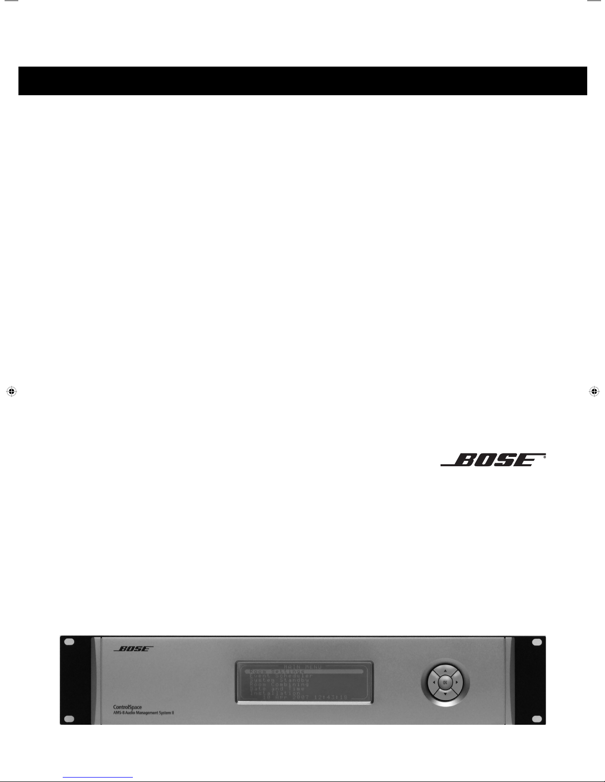
BOSE® ControlSpace™ AMS-8 Audio Management System
Safety Instructions & Installation Guide
Sikkerhedsinstruktioner og installationsvejledning
Sicherheitshinweise & Installationshandbuch
Instrucciones de seguridad y guía de instalación
Consignes de sécurité et notice d’installation
Istruzioni di sicurezza e guida all’installazione
Veiligheidsinstructies & installatiehandleiding
Instrukcja obslugi i bezpiecznego uzytkowania
Säkerhetsanvisningar & Installationsguide

The manufacturer reserves specification privileges. Information in this manual is subject to change without prior notice or obligation.

English
Table of contents
1. Safety information
Important safety instructions
Declaration of conformity
2. Introduction
3. System installation
3.1 Front panel ControlSpace™ AMS-8
3.2 Rear panel ControlSpace™ AMS-8
3.3 Wall Controller configuration
3.4 User interface connections
3.5 System layouts
3.6 Wall Controller connections
3.7 Local Input Module connections
3.8 Paging Panel connections
3.9 General purpose inputs/outputs
3.10 Audio input and output connections
4. Optional system components
5. Upgrade to a ControlSpace
™
AMS-8 II system
6. Troubleshooting
7. Tec hnical specifications
Annex A. ControlSpace
™
AMS-8 system examples
Annex B. User Interface mounting instructions
European sales offices
4
6
7
8
9
10
11
12
15
15
16
17
18
19
21
22
23
24
26
28

4
English
1. Safety information
Caution marks on the product
These CAUTION marks are located on the back of the product.
The lightning flash with arrowhead symbol, within an equilateral triangle, is intended to alert
the user to the presence of un-insulated dangerous voltage within the system enclosure that
may be of sufficient magnitude to constitute a risk of electric shock.
The exclamation mark within an equilateral triangle, as marked on the system, is intended
to alert the user to the presence of important operating and maintenance instructions in this
installation guide
Important safety instructions
1. Read these instructions.
2. Keep these instructions for future reference.
3. Heed all warnings on the product.
4. Follow all instructions.
5. Do not use this apparatus near water or moisture.
6. Clean only with a dry cloth.
7. Do not block any ventilation openings. Install in accordance with the manufacturer’s instructions.
To ensure reliable operation of the product and to protect it from overheating, put the product in a
position and location that will not interfere with its proper ventilation.
8. Do not install near any heat sources, such as radiators, heat registers, stoves, or other apparatus
(including amplifiers) that produce heat.
9. Do not defeat the safety purpose of the polarised or grounding type plug. A polarised plug has two
blades with one wider than the other. A grounding-type plug has two blades and a third grounding
prong. The wider blade or third prong are provided for your safety. If the provided plug does not fit
in your outlet, consult an electrician for replacement of the obsolete outlet.
10. Protect the power cord from being walked on or pinched, particularly at plugs, sockets etc.
11. Only use attachments/accessories specified by the manufacturer.
12. Use only with the cart, stand, tripod, bracket, or table specified by the manufacturer or sold with
the apparatus. When a cart is used, use caution when moving the cart/apparatus combination to
avoid injury from tip-over.
13. Unplug this apparatus during lightning storms or when unused for long periods of time – to prevent
damage to the product.
14. Refer all servicing to qualified service personnel. Servicing is required when the apparatus has been
damaged in any way such as: power-supply cord or plug is damaged; liquid has been spilled or objects
have fallen into the apparatus; the apparatus has been exposed to rain or moisture, does not operate
normally, or has been dropped. Do not attempt to service this product yourself. Opening or removing
covers may expose you to dangerous voltages or other hazards. Please call Bose to be referred to an
authorised service centre near you.
15. To prevent risk of fire or electric shock, avoid overloading wall outlets, extension cords, or integral
components.
1. Important safety instructions

English
5
1. Safety information
16. Do not let objects or liquids enter the product as they may touch dangerous voltage points or
short-out parts that could result in a fire or electric shock.
17. See product enclosure for safety related markings.
18. No naked flame sources, such as lighted candles, should be placed on the apparatus.
WARNING: To reduce the risk of fire or electric shock, do not expose the ControlSpace
™
AMS-8 to rain or
moisture.
WARNING: The apparatus should not be exposed to dripping or splashing, and objects filled with liquids,
such as vases, should not be placed on the apparatus. As with any electronic product, use care not to spill
liquids into any part of the system. Liquids can cause a failure and/or fire hazard.
Information about products that generate electrical noise
If applicable, this equipment has been tested and found to comply with the limits for a Class A digital
device, pursuant to Part 15 of the FCC rules. These limits are designed to provide reasonable protection
against harmful interference in a residential installation. This equipment generates, uses, and can radiate
radio frequency energy and, if not installed and used in accordance with the instructions, may cause
harmful interference to radio communications. However, this is no guarantee that interference will not
occur in a particular installation. If this equipment does cause harmful interference to radio or television
reception, which can be determined by turning the equipment off and on, you are encouraged to try to
correct the interference by one or more of the following measures:
• Reorient or relocate the receiving antenna.
• Increase the separation between the equipment and receiver.
• Connect the equipment to an outlet on a different circuit than the one to which the receiver
is connected.
• Consult the dealer or an experienced radio/TV technician for help.
Note: Unauthorised modification of the receiver or radio remote pasted from a hifi-product could void the
user’s authority to operate this equipment.
This product complies with specifications. The information furnished in this installation guide does not
include all of the details of design, production, or variations of the equipment. Nor does it cover every
possible situation which may arise during installation, operation, or maintenance. If you need assistance
beyond the scope of this installation guide, please contact one of our European sales offices listed on the
last page of this installation manual.

6
English
Declaration of Conformity
The manufacturer of this amplifier hereby declares that this product, including its accessories,
is in compliance with the following standards:
EMC Directive 89/336/EEC (Electromagnetic Compatibility)
EN-55103-1
EN-55103-2
Low Voltage Directive 73/23/EEC
EN-60065:2002 7th Edition
Rack mounting considerations
The audio signal processor requires two 4.4 cm (1.75”) rack space units with 32.5 cm (12.8”) inside depth.
When mounting, use four screws with washers to prevent marring the front panel. Neoprene rubber
washers are a good choice because they grip the screw heads and prevent the screws from backing out
due to vibration or during transportation.
Caution: If the unit is rack-mounted and the rack is transported, you must mechanically support the rear
of the processor. You can place a shelf across the rear of the processor or use brackets to support the rear
unit.
General precautions & Ventilation
Caution: Place the unit where it will be protected from heat and allow adequate ventilation. Place the
unit away from direct heat sources, such as heating vents and radiators. Make sure the air can circulate
freely behind, beside and above the unit.
If the unit is placed under or above an amplifier, make sure a single unit ventilation plate is placed
between the 2 devices.
Do not allow the chassis to exceed the maximum operating temperature of 50ºC. Be aware of conditions in
an enclosed rack that may increase the temperature above above ambient room conditions.
Cautions: Be sure all the fine cores of the wire are twisted together and contained within the connector.
If even one core is loose it can touch the adjacent terminal, which may cause a short circuit.
1. Safety information

English
7
Introduction
The BOSE
®
ControlSpace™ AMS-8 Audio Management System is a flexible, expandable and high quality
audio signal processor for audio distribution applications such as restaurants, shops, bars, offices, hotels,
conference facilities and sport venues. The main unit includes eight line inputs and eight line outputs. Four
available audio slots allow the addition of up to 8 more audio inputs (2 inputs per card).
For more zones, up to 10 AMS-8 system racks can be linked together per system. Each added system rack
adds 8 zones to the system. Multiple choices of user interfaces are available to give end-users simple and
easy-to-use control of their ControlSpace
™
AMS-8 system.
The BOSE® ControlSpace™ AMS-8 Live Installer software is used to design systems and configure
the AMS-8 and user interfaces. The software runs on a PC and communicates with the AMS-8 system
using serial communication (RS232), or optional via ethernet (requires PC Kit).
Quick start
• Connect the audio inputs and audio outputs to the ControlSpace™ AMS-8 system. (In the case of 2 or
more systems racks: connect these racks by using audio link cards, audio link cables and high speed
RS485 rack links: see also chapter 3.5).
• Turn on the ControlSpace™ AMS-8 system. Because of the default settings the system is now in operation.
After each start up of the ControlSpace™ system, the default settings will be recalled. This means that the
system will play at the default source and default volume level as set in the installation menu.
NOTE: To update to features and functions of a ControlSpace™ AMS-8 II system, see chapter 5
2. Introduction
2. Introduction
Abbreviations
CS-WC ControlSpace™ AMS-8 Wall Controller
CS-PP ControlSpace™ AMS-8 Paging Panel
CS-LIM ControlSpace™ AMS-8 Local Input Module
CS-RC ControlSpace™ AMS-8 Remote Control
CS-TIC ControlSpace™ AMS-8 Twin Input Card
CS-TOC ControlSpace™ AMS-8 Twin Output Card
CS-EC ControlSpace
™
AMS-8 Ethernet Card
CS-MSC ControlSpace™ AMS-8 Message Storage Card
CS-DIC ControlSpace™ AMS-8 Digital Input Card
CS-TTC ControlSpace™ AMS-8 Twin Tuner Card
CS-HUB ControlSpace™ AMS-8 RS485 Hub
CS-SCI ControlSpace™ AMS-8 Serial Code Interface
PC-Kit ControlSpace™ AMS-8 PC Kit (incl. Ethernet Card)
Features and functions
• Expandable and flexible cardframe architecture
• 8 (up to 16) analogue line level input channels
• Eight analogue line level output channels
• GPIO: 8 general purpose control inputs (to activate
messages, roomcombining presets or room standby/
mute) and 1 general purpose control output
• Design, configuration and system control via
PC-based software programs
• Digital signal processing including: BOSE speaker
EQs, Dynamic EQ, delay, gain control and source
selection.
• LCD screen and navigation buttons
• Wall Controller functionality
(optional IR remote control)
• Local Input Module functionality
• Paging Panel functionality
• Messaging functionality
(optional Message Storage Card is required)
• Tuner functionality
(optional Twin Tuner Card is required)
• Automatic detection of input card type
• Room Combining functionality
• Event Scheduling functionality

8
English
1
2
1. LCD SCREEN
The LCD screen displays the control menus and the possible settings for each menu item.
2 . NAVIGATION BUTTONS
With the ‘up’ and ‘down’ buttons one can scroll through the menu items, whilst the ‘left’ and ‘right’
buttons allow the value of the selected menu item to be changed. The ‘OK’ button confirms the current
selection, eg. with the ‘Exit’ menu item highlighted, pressing ‘OK’ will return to the previous menu level.
3.1 Front panel ControlSpace™ AMS-8
3. System Installation
English
9
BoseCorporation, Framingham, MA01701-9168
MadeinTheNetherlands
SerialNumber:
SystemRack
MODEL:
AVIS:Risquede chock électrique,ne pas
ouvrir
RISKOFELECTRICSHOCK
DONOTOPEN
CAUTION
!
CSTIC
RCA Input Connector
3-pin Input Euro Blok Connector
(Balanced line level)
CSTOC
1
2
3
4
5
6
7
8
9
1
2
3
4
5
6
7
8
9
1
2
3
4
5
6
7
8
9
DB9 Female
Pin 1: Contact 1
Pin 2: Contact 2
Pin 3: Contact 3
Pin 4: Contact 4
Pin 5: Contact 5
Pin 6: Contact 6
Pin 7: Contact 7
Pin 8: Contact 8
Pin 9: Output
Pin 10: Common
Rack link 1 (high speed)
Rack link 2 (high speed)
CS-WC & CS-PP Bus 1 (low speed)
CS-WC & CS-PP Bus 2 (low speed)
RS232portpinout
Straight shielded cable
(20 meters max.)
2. TX
3. RX
5. GND
1
3
5
7
9
2
4
6
8
10
1
3
5
7
9
2
4
6
8
10
1
3
5
7
9
2
4
6
8
10
Line inputs (1-16)
Line outputs (1-8)
RS-485 card
RS-232 & GPIO card
AudioLinkCardslot
Slot for Audio Link Card to link the connected
analog sources between Controlspace AMS-8
Audio Managment Systems.
(Unbalanced line level)
3-pin Input Euro Blok Connector
(Balanced line level)
RCA Input Connector
(Unbalanced line level)
RCA Input Connector
3-pin Input Euro Blok Connector
(Balanced line level)
(Unbalanced line level)
3-pin Input Euro Blok Connector
(Balanced line level)
RCA Input Connector
(Unbalanced line level)
ToCSPP/CSWC
Bus1
Bus2
Rack
Link2
Rack
Link1
I/OLink
PCLink
785
6
3
4
1
2
785
6
3
4
1
2
15
16
13
14
11
12910
1
4
5
8
9
12
13
16
SourceInputs
Audio
Link
LineOutputs
1 2 3 4 5
2
1
3
4
5
1
2
3
4
5
6
7
8
9
1
2
3
4
5
6
7
8
9
DB9 Female
Pin 1: Contact 1
Pin 2: Contact 2
Pin 3: Contact 3
Pin 4: Contact 4
Pin 5: Contact 5
Pin 6: Contact 6
Pin 7: Contact 7
Pin 8: Contact 8
Pin 9: Output
Pin 10: Common
RS232 port pin out
Straight shielded cable
(20 meters max.)
2. TX
3. RX
5. GND
1
3
5
7
9
2
4
6
8
10
1
3
5
7
9
2
4
6
8
10
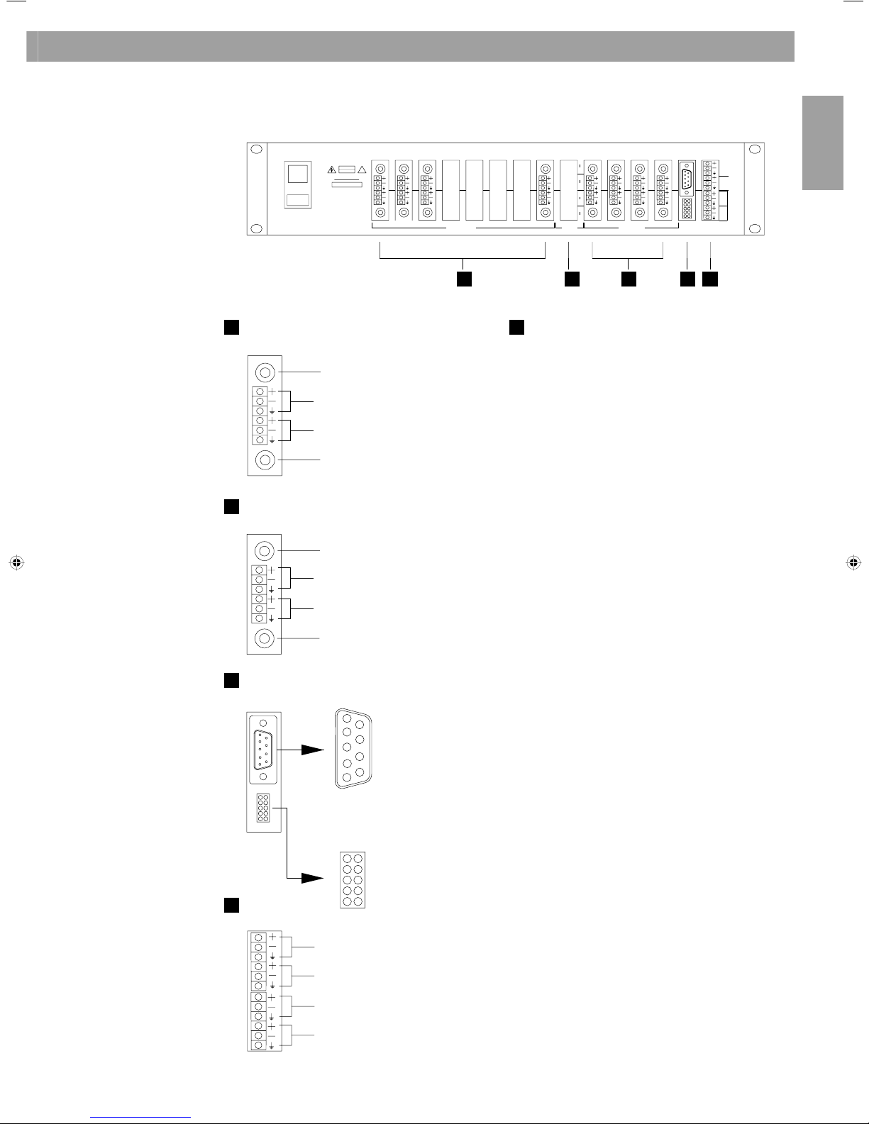
3. System Installation
3.2 Rear panel ControlSpace™ AMS-8
RCA Input Connector
(Unbalanced line level)
3-pin Input Euro Block Connector
(Balanced line level)
3-pin Input Euro Block Connector
(Balanced line level)
RCA Input Connector
(Unbalanced line level)
Line inputs (1-16)
CS TIC
RCA Output Connector
(Unbalanced line level)
3-pin Output Euro Block Connector
(Balanced line level)
3-pin Output Euro Block Connector
(Balanced line level)
RCA Output Connector
(Unbalanced line level)
Line outputs (1-8)
CS TOC
RS232 & GPIO card
Rack link 1 (high speed)
Rack link 2 (high speed)
CS-WC & CS-PP Bus 1 (low speed)
CS-WC & CS-PP Bus 2 (low speed)
RS485 card
Audio Link Card slot
Slot for Audio Link Card to link two ControlSpace™ AMS-8
Audio Management Systems. An Audio Link Card is only
required in the master rack. Add one Audio Link Cable set
per four sources to be linked.
GPIO pinout:
1: Contact 1
2: Contact 2
3: Contact 3
4: Contact 4
5: Contact 5
6: Contact 6
7: Contac t 7
8: Contact 8
9: Out
10: Common
DB Female
RS232 port pin out
Straight shielded cable
(20 meters max.)
2. TX
3. RX
4. GND
10
English
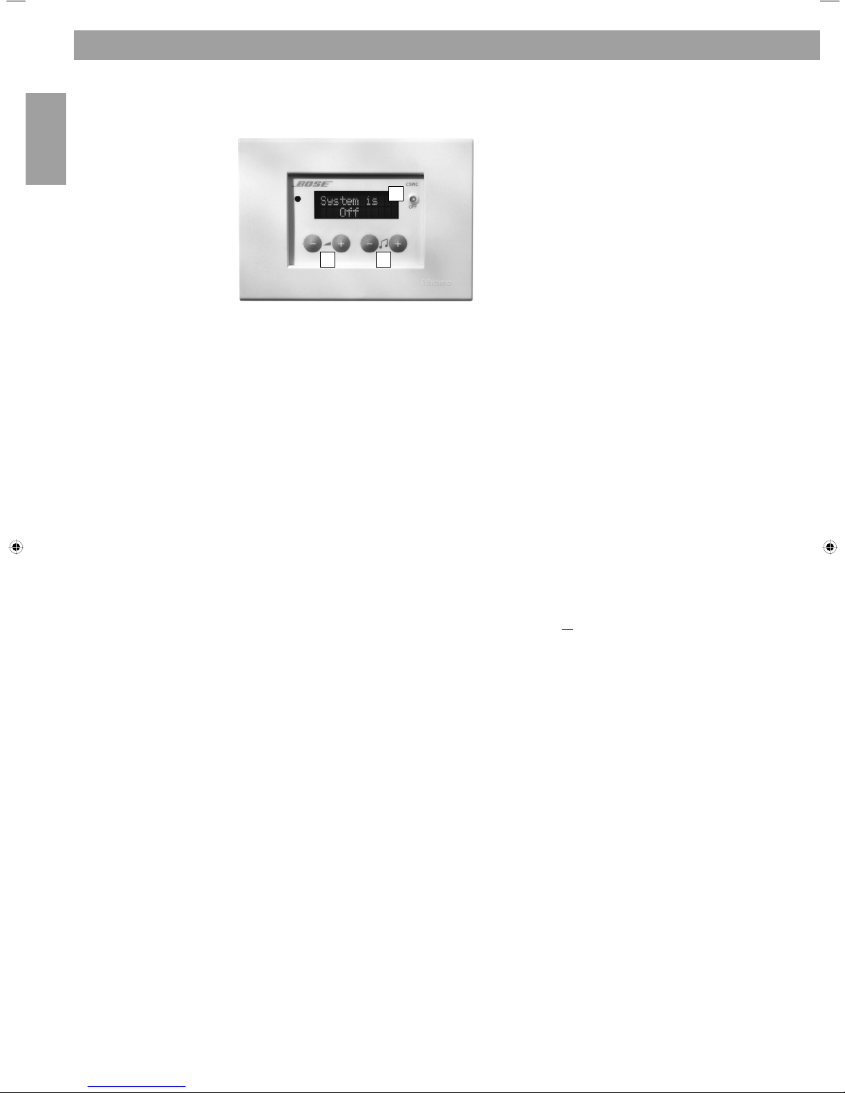
1
2 3
Before configuring the ControlSpace™ AMS-8, one needs to select a number for each wall controller (1..8),
this is normally done the first time the wall controller is connected to the system rack. A few seconds after
the wall controller has been connected to the system rack, the Firmware version is displayed on the LCD
screen, followed by “Select WC..”. Use the channel buttons to select the appropriate number and confirm
this choice by pressing the volume down (-) button. If multiple wall controllers need to be used to control
the same room, one should select the same number on these wall controllers as well. In a situation like
this, all wall controllers need to be connected to the same rack frame.
If a wall controller already has a number then it can be altered as follows:
1. Switch the wall controller off (press the channel down (-) button as many times as needed
until the wall controller is switched off)
2. Press and hold the channel down (-) button
3. Press the volume up (+) and down (-) buttons at the same time (After the LCD screen has
displayed the Firmware version it displays the actual number, e.g. “WC2”).
4. Now you can use the channel buttons to select the appropriate number and confirm this
choice by pressing the volume down(-) button in the same way as before.
If the system consists of two or more ControlSpace
™
AMS-8 racks, all racks use numbers (1..8).
For the first rack numbers 1..8 are used for output channels 1..8, for the second rack output channels 9..16
up to the tenth rack for outputs 73..80.
Changing room settings using the wall controller
For the room where the wall controller is installed one can adjust the audio settings using the hidden
menu in the wall controller. Follow the procedure below to enter this menu:
1. Switch the wall controller off (press the channel down (-) button as many times
as needed until the wall controller is switched off)
2. Press and hold the volume down (-) button
3. Press the channel up (+) and down (-) buttons at the same time
In the hidden menu the following functions can be set or altered:
a. default channel b. bass level c. treble level
d. dynamic EQ e. Bose speaker EQ f. maximum volume level
g. paging volume level h. delay i. default volume level
The channel buttons allow you to scroll through the menu items whilst the volume buttons allow you to
change the settings for the selected item.
To leave the hidden menu, press the channel up (+) and down (-) button at the same time.
3.3 Wall Controller configuration
1. LCD SCREEN
2. VOLUME KEYS
3. CHANNEL KEYS
3. System Installation
English
11
4 5
6
3
21
21
5
43
3.4 User interfaces connections
ControlSpace™ AMS-8
Wall Controller
ControlSpace™ AMS-8
Paging Panel
ControlSpace™ AMS-8
Local Input Module
Power supply
Voltage 12-24VDC, +/-20% 12-24VDC, +/-10% 24VDC, +5%/-10%
Current @ 12VDC 50mA typ
@ 24VDC 30mA typ
@ 12VDC 140mA typ
@ 24VDC 70mA typ
@ 24VDC 60mA typ
Recommended power
supply*
BOSE CS AMS-8
24VDC, 2.7A stabilised
power supply
BOSE CS AMS-8
24VDC, 2.7A stabilised
power supply
BOSE CS AMS-8
24VDC, 2.7A stabilised
power supply
RS485 wiring**
Max Distance
(/with Hub)
600m
(1200m)
600m
(1200m)
Not applicable
Termination *** 120ohm 120ohm Not applicable
Cable type 1 pair twisted and
shielded
1 pair twisted and
shielded
Not applicable
Nom. Cap. 40pF/m Nom. Cap. 40pF/m Not applicable
Nom. Imp. 124ohm Nom. Imp. 124ohm Not applicable
Nom. Att. 2dB @ 1MHz Nom. Att. 2dB @ 1MHz Not applicable
Recommended cable BOSE CS AMS-8
communication/
power cable (blue) for
CS-WC/CS-PP
BOSE CS AMS-8
communication/
power cable (blue) for
CS-WC/CS-PP
Not applicable
Audio wiring Not applicable Standard Mic/Line
cable, 1 pair with
shielding
BOSE CS AMS-8
audio/power cable
for (yellow) CS-LIM
* Note: If the above mentioned power supply is not used, any other power supply used in Europe must be
compliant with EN/IEC 60950.
** Required RS485 wiring
Always connect the components in a daisy-chain configuration (rather than in a star or other
configuration). Star wiring is only allowed using the CS-HUB. Be sure to separate the data cable from
power wiring (>50V) on the cable tray or other cable management.
*** Termination
The termination jumper should be placed on the last user interface (CS-WC or CS-PP), located at the end of
each RS485 communication line.
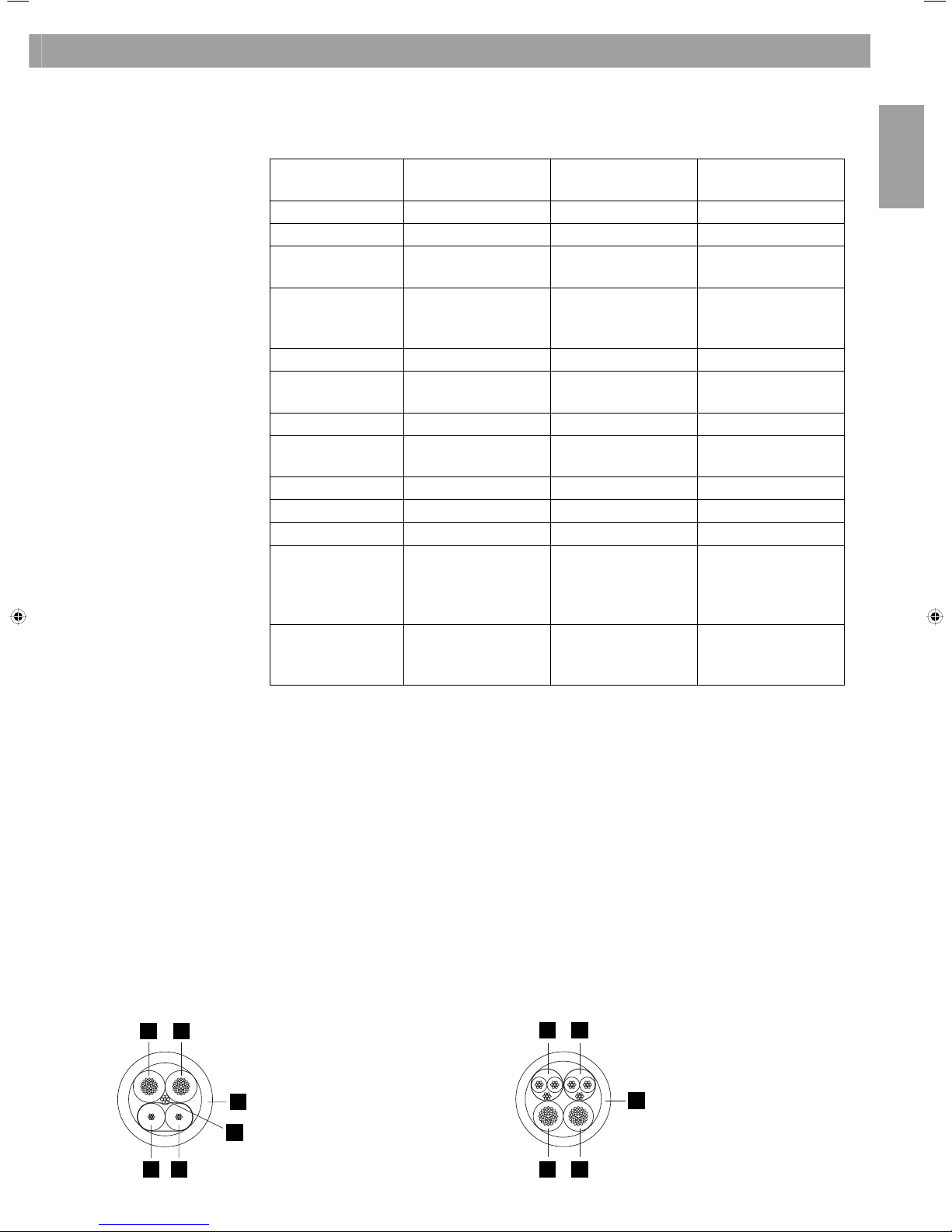
CS AMS-8 communication/power cable
1. Blue = RS485 communication ‘+’
2. Clear = RS485 communication ‘–’
3. Drainwire = RS485 communication ‘GND’
4. Red = power ‘24VDC’
5. Black = power ‘ground’
6. Blue jacket
CS AMS-8 audio/power cable
1. Yellow = balanced line cable (shielded)
2. Green = balanced line cable (shielded)
3. Red = power ‘24VDC’
4. Black = power ‘ground’
5. Yellow jacket
3. System Installation
12
English
*
*
*
*
600 m
600 m
600 m600 m
600 m
RS485
HUB
3. System Installation
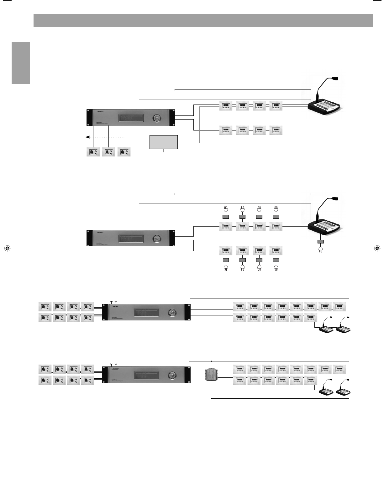
3.5 System layouts
Two RS485 communication lines and a central power supply:
Two RS485 communication lines and localpower supplies:
RS485 communication line maximum distance:
Or:
NOTE:
* Termination jumper should be placed on the last user interface (CS-WC or CS-PP),
located at the end of each RS485 communication line.
More system examples can be found in Annex A.
Audio/Microphone cable
Power supply
24VDC 2-7A
RS-485
RS-485
DC 24V
input
RS-485
RS-485
PSU
PSU
Audio/Microphone cable
Audio/Microphone cable
600m
600m

English
13
3. System Installation
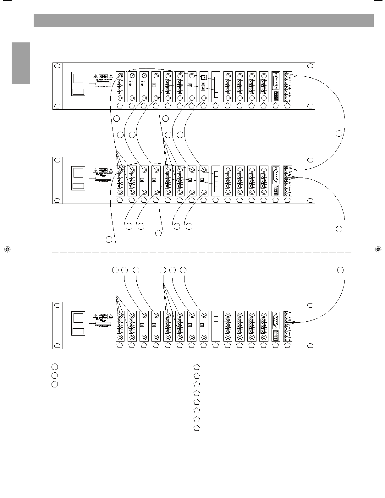
Adding ControlSpace™ AMS-8 units to create a system up to 80 audio zones
Optional Audio Link Cards are required. The number of required Audio Link Cable sets depends on the
total number of connected sources (incl. paging panels and internal tuner cards). One Audio Link Cable set
is required to link up to four analogue sources.
For each added rack frame, also add a piece of communication cable (2 wires + shielding) to link the
‘Racklink 1 or 2’ connection of the added rack to a free racklink connection on the previous installed rack.
Make sure that the termination jumpers are only placed on the RS485 communication cards of the first and
last AMS-8 system.
Master & Slave configuration
1) Turn each AMS-8 unit on, while pressing the arrow UP and RIGHT navigation button at the same time.
This action will activate the Bootloader mode.
2) Select ‘Master’ for the first AMS-8 unit in the system. Select the appropriate number of racks on the
master AMS-8 unit, e.g.: “Nr. of Racks: 10”
3) Every added rack will be a ‘Slave’ rack with a number starting at 2, 3, 4, 5 …. up to 10. E.g.: ”Select
rackNr: 2”
4) Notice the ‘live-mask’ indication at the bottom of the graphic display. This indicates the number of AMS8 systems which are installed and connected. This live-mask is displayed as follows:”Racks: 00000011
11111111”, which indicates 10 installed AMS-8 systems
5) As soon as all slave units have been detected, select ‘Finish’ on the master unit.
6) Re-start all racks (due to re-grouping of all the racks), by turning all units off and on again.
NOTE: To link the digital signal of a Message Storage Card, Digital Input Card or the digital signal
(instead of analogue) of the Twin Tuner Card, one should add a Digital Input Card and Digital
Coaxial Cable (RCA-RCA) per added rack frame.
14
English
Rack 1 (Master)
Rack 2 (Slave)
Rack 10 (Slave)
3
1
Digital coax cable (75 Ohm)
2
CS-AMS-8 Link cable
3
RS485 communication cable (120 Ohm)
3
4
3
15
6666
7
8
5
6666
7
8
33333
111
5
6666
7
8
1
Twin Input Card
Message Storage Card
Digital Input Card
Twin Tuner Card
Audio Link Card
Twin Output Card
PC Link - I/O Link
RS485 Communication (High/Low speed)
8
7
6
5
4
3
2
1
32
41
11 11
11 11
44 44
22
11 11
2
2
2
11
2
11
3
3. System Installation
English
15
voice
flat
voice
flat
2 5 4
3 1
1
2
3
4
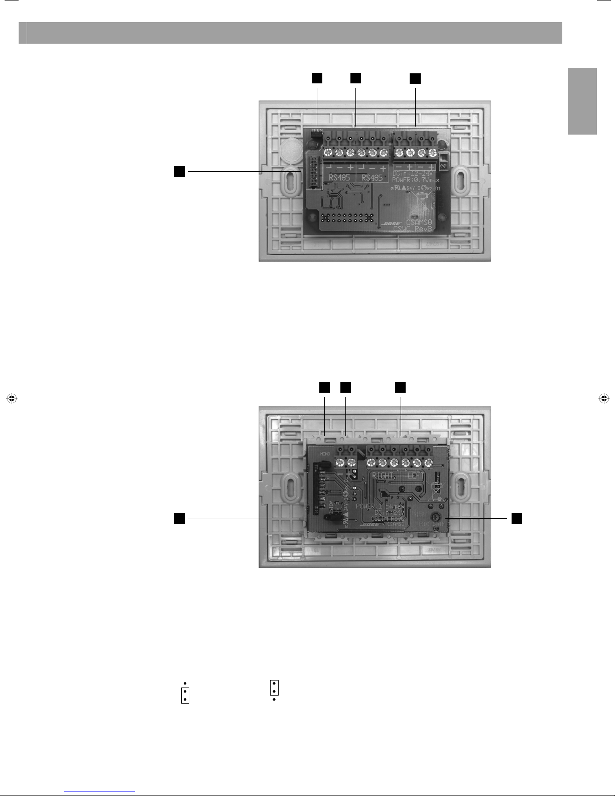
3.6 CS-WC connections and settings
1. Termination jumper, see NOTE in chapter 3.5
2. RS485 connector
3. Power supply connector (12-24Vdc)
4. Firmware update connector
NOTE: See Annex B. Wallpanel mounting instructions
1. The CS-LIM is equipped with a microphone gain adjuster, also accessible from the frontpanel by using a ‘0’
screw driver. Turn the adjuster anti-clockwise (seen from the front) to decrease the gain to a minimum of
32dB. Turn the adjuster clockwise to increase the gain to a max of 66dB. The factory gain setting is 38dB.
2. To change the CS-LIM from stereo to mono, this jumper needs to be set. In a mono configuration,
the audio cable should be connected to the LEFT output (jumper is left open).
3. To activate a voice EQ (optimized EQ for speech) for the microphone input,
the jumper needs to be moved from FLAT to VOICE
= flat response = voice EQ
4. Stereo, balanced line output connector.
5. Power supply connector (24Vdc).
NOTE: See Annex B. Wallpanel mounting instructions
3.7 CS-LIM connections and settings
3. System Installation
16
English
3
2
1
6
4
5
7 7
8
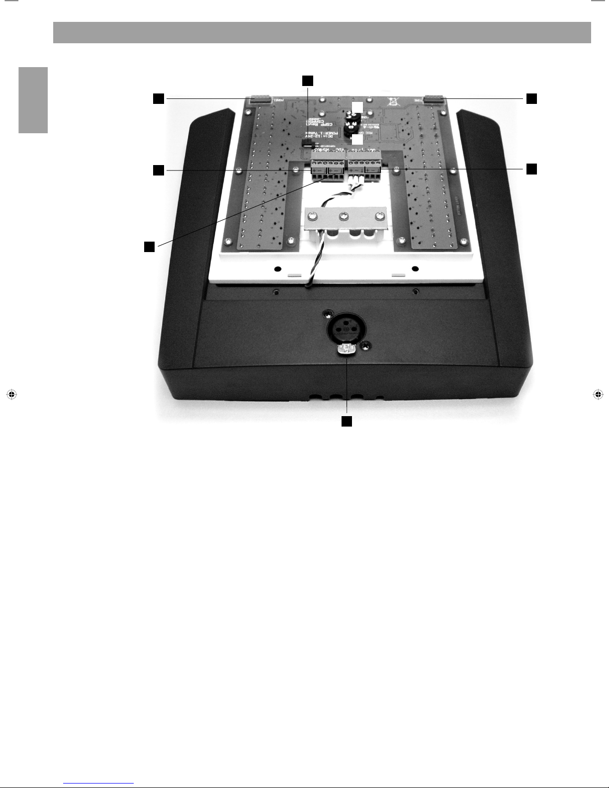
3.8 CS-PP connections and settings
3. System Installation
The CS-PP is equipped with voice EQ, a microphone gain adjuster and a chime (attention signal) gain
adjuster. In order to be able to adjust both gains, and to connect the CS-PP, one needs to remove the
plastic inlay (on top of the frontplate of the CS-PP), then remove the 4 screws and lift the front panel out
of the housing. The two adjusters are located at the bottom of the panel.
NOTE: Ensure not to short any connections or electronic components
1. Microphone gain: turn the adjuster anti clockwise to decrease the gain with a minimum of 32.6 dB. Turn
the adjuster clockwise to increase the gain to a max of 60.1 dB. The factory gain setting is 38 dB.
2. Chime gain: use the adjuster to increase or decrease the level of the chime signal.
3. Termination jumper, see NOTE in chapter 3.5.
4. RS485 connector.
5. Power supply connector, 12-24Vdc (only 2 of the 3 pins are used!).
6. Balanced line output connector.
7. Firmware update connector.
8. XLR-connector for microphone with 22Vdc phantom power
English
17
1..8
10
24 Vdc
CS-AMS-8
+
-
24 Vdc
9
10
Open collector
Max. 50mA
CS-AMS-8
+
-
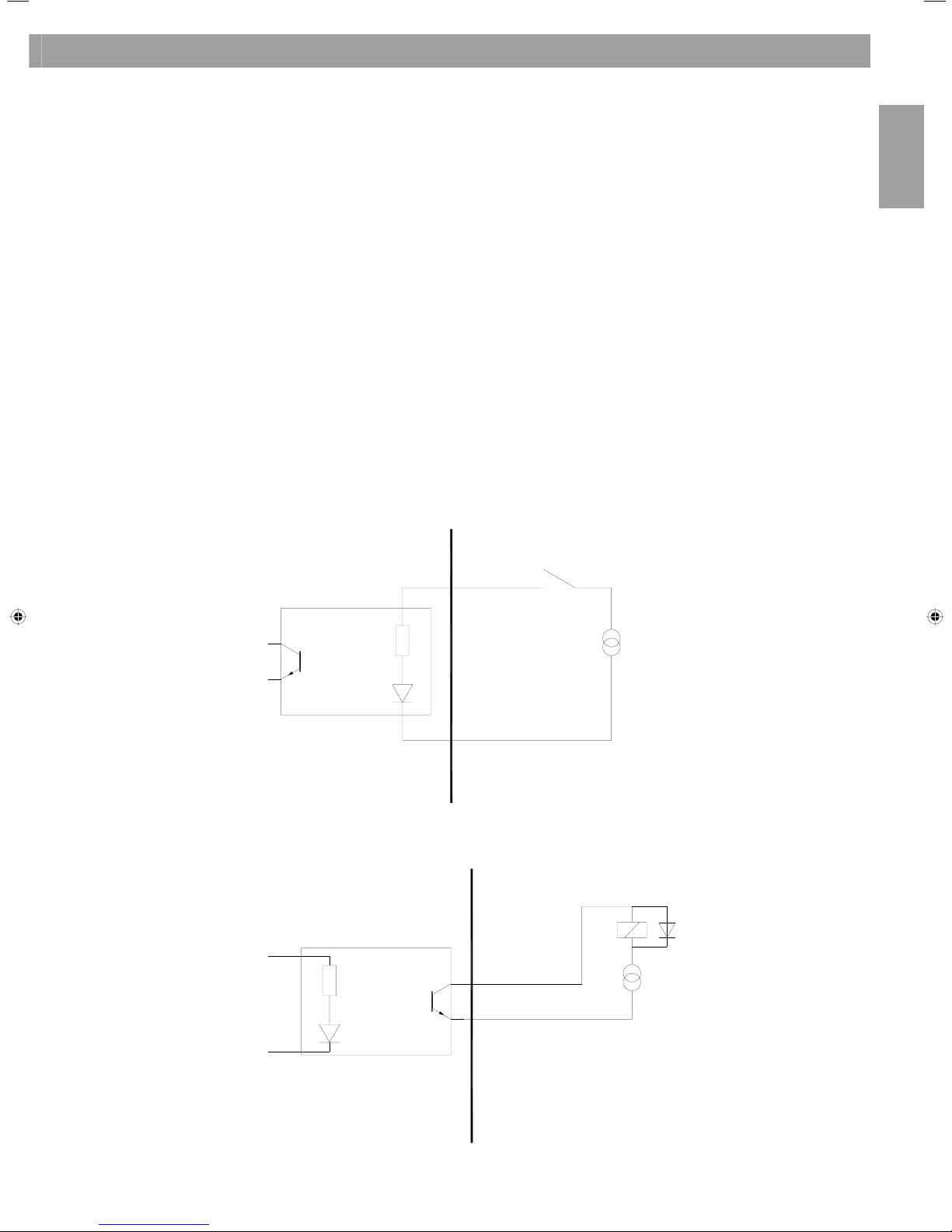
ControlSpace™ AMS-8 includes one GPIO/RS232 card (see also chapter 3.2).
Up to 40 GPIO contacts (8 per rack, max 5 rack frames in total) can be used to trigger up to 40 messages,
up to 40 room combine presets or the Room Standby function (‘mute’) on different or all outputs.
The contacts are triggered by applying 24VDC between the specific contact and the common ground pin.
NOTE: A ‘Pulse’ contact will play a message once. A ‘Hold’ contact will play and repeat a message until
the contact is released. Use a hold contact to activate room combining or standby mode (release this
contact to de-activate these two functions)
Characteristics
• 8 isolated inputs
• 1 isolated output
• Inputs can be used for message routing, room combining or to put an output or group of outputs in
standby mode (outputs will return to default value when contact is released again)
• Open collector output is activated when one of the eight inputs is activated
Wiring diagram of the 8 input contacts
Wiring diagram of open collector output
3. System Installation
3.9 General Purpose Inputs/Outputs (GPIO)
CS-AMS-8
CS-AMS-8
18
English
⊥
-
+
L
R
⊥
-
+
L
R
L
R
S ⊥
T +
R -
TR S
TS
T +
S-
⊥
T
S
S
S -
⊥
T +
12
3
T
S
S -
⊥
T +
2 +
⊥
1
3 -
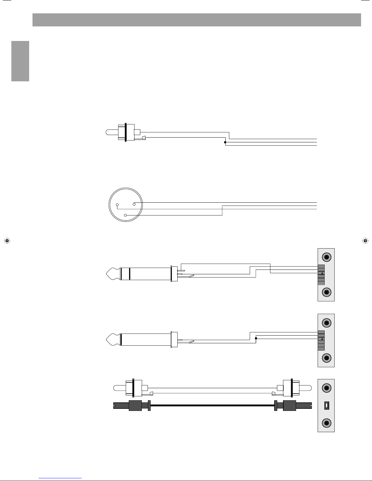
Audio sources can be connected to the balanced and unbalanced line inputs and outputs using one of the
following cable types:
Source connector ControlSpace™ AMS-8 Audio Inputs and Outputs
3.10 Audio source in and output connections
3. System Installation
RCA
XLR
Phone plug (balanced)
Phone plug (unbalanced)

English
19
4. Expansion options
The standard ControlSpace™ AMS-8 includes:
• 8 line level analogue audio input channels (CS-TIC)
• 8 line level analogue audio output channels (CS-TOC)
• 8 general purpose control contact inputs
• 1 general purpose control contact output
• 1 RS232 communication port
The ControlSpace
™
AMS-8 system can be expanded with additional user interfaces,
optional cards and communication interfaces.
Optional user interfaces:
CS-PP - ControlSpace™ AMS-8 Paging Panel
With the ControlSpace™ AMS-8 Paging Panel both pre-recorded and
realtime voice messages can be relayed to a selected group of zones.
CS-WC - ControlSpace™ AMS-8 Wall Controller
With the ControlSpace™ AMS-8 Wall Controller the channel can be selected and
the volume of the audio signal can be adjusted locally.
CS-LIM - ControlSpace™ AMS-8 Local Input Module
The ControlSpace™ AMS-8 Local Input Module allows a local source
(line or microphone) to be added to the system.
CS-RC - ControlSpace™ AMS-8 Remote Control
The ControlSpace™ AMS-8 Remote Control (infrared)
allows easy control of the Wall Controller up to 5 meters.
Optional Cards:
CS-TIC - ControlSpace™ AMS-8 Twin Input Card
Up to four ControlSpace™ AMS-8 Twin Input Cards can be added per frame to provide an additional 8 line
analogue audio input channels.
CS AMS-8 Audio link Card
The ControlSpace™ AMS-8 Audio Link Card allows up to ten frames to be connected together.
Audio link cables are also required.
4. Optional system components

20
English
4. Expansion options
CS-EC - ControlSpace™ AMS-8 PC Kit
The RS232 communication card can be replaced by a ControlSpace™ PC Kit which includes an Ethernet Card
(including GPIO connector) and software to control the AMS-8 system via ethernet. This software allows
to control a room in the same way as the Wall Controller and it can be used for paging/messaging and
activation of roomcombining presets and scheduled events. The PC Kit allows ethernet connections for
80 Single users, 14 Multi users and 1 connection at Installer level.
CS-MSC - ControlSpace™ AMS-8 Message Storage Card
The message storage card occupies one CS-TIC (input card) slot and allows pre-recorded messages to
be stored and activated by the appropriate button on the paging panel, via the Event scheduler or via
the GPIO contacts. Software to configure the CS-MSC or to record messages is included.
CS-DIC ControlSpace™ AMS-8 Digital Input Card
The digital input card can be used to add a digital stereo input signal. It also needs to be used to link a
CS-MSC, CS-TTC or CS-DIC itself to another rack.
CS-TTC ControlSpace™ AMS-8 Twin Tuner Card
The Twin Tuner Card can be used to add 1 stereo or 2 mono tuners to the system.
Optional communication interfaces:
CS-SCI ControlSpace™ Serial Code Interface
The Serial Code Interface converts serial codes, sent from or to control devices like Crestron/AMX, to
control the AMS-8 system. The CS-SCI also contains 16 programmable open collector outputs (each
coupled to a single Room). Each output can be made active when a Room is active or when a page is send
to this Room (e.g. for 100Volt attenuator over-ride).
CS-HUB ControlSpace™ RS485 Communication Hub
RS485 communication hub (CS-HUB) can be used to create a star network to connect up to 5 ControlSpace
user interfaces (CS-WC/CS-PP). It can also be used to create larger distances between AMS-8 units and/
or Serial Code Interfaces, but also to enlarge the distance between wall controllers and paging panels
(connected to a single RS485 communication bus.).

English
21
5. Upgrade to a ControlSpace™ AMS-8 II system
1) Check the Bootloader firmware version, which is shortly shown on the display after the AMS-8 unit is
turned on. Proceeding with below steps is only possible if the Bootloader Firmware version is V2.116
or higher. If lower, the unit requires a bootloader firmware update which can only be performed
by Bose employees
2) Connect all AMS-8 units in the system (10 max) using the racklink connection (see also chapter 3.5)
3) Make sure that the termination jumpers are only placed on the RS485 communication cards of the
first and last AMS-8 system (all other jumpers should not be set)
4) Turn each AMS-8 unit on, while pressing the arrow UP and RIGHT navigation button at the same
time. This action will activate the Bootloader mode
5) Select ‘Master’ for the first AMS-8 unit in the system. Select the appropriate number of racks on the
master AMS-8 unit, e.g.: “Nr. of Racks: 10”
6) Every added rack will be a ‘Slave’ rack with a number starting at 2, 3, 4, 5 …. up to 10.
E.g.: ”Select rackNr: 2”
7) Notice the ‘live-mask’ indication at the bottom of the graphic display. This indicates the number of
AMS-8 systems which are installed and connected. This live-mask is displayed as follows:
”Racks: 00000011 11111111”, which indicates 10 installed AMS-8 systems
8) As soon as all slave units have been detected, select ‘Finish’ on the master unit.
This will (temporary) set the bootloader configuration
9) Connect your computer to the master rack and start the Bootloader Multi-Installer software
10) Upload the (latest) firmware into the AMS-8 units
11) Wait until the upload and re-update of all units is finished
12) Set the 1st (upper) rack to ”Rack-1 Mst” (master) again and enter the number of slaves (if needed,
first repeat step 4 again to do this)
13) Set every slave rack to the correct slave number (”Rack-2” or higher), see also step 5
14) Re-start all racks (due to re-grouping of all the racks), by turning all units off and on again
15) Perform a Total Factory Restore (select this option in the installation menu) on the master rack and
wait until the flash update is finished (displayed as: “Updating flash 202”)
16) Re-start all racks again (to implement the new DataFlash memory settings), by turning all units off
and on again
17) Update all Bose EQ curves using the Live Installer Software
18) Update to a ControlSpace
™
AMS-8 II system is now finished
Use the Live Installer Software or the Graphic display + navigation buttons to configure the AMS-8 units.
Previously saved BDF-files (Bose Data Files) can not be used anymore to restore into the AMS-8 units (due
to new DataFlash memory settings). However, after a unit is re-configured, the new created BDF-file can
be saved and re-opened to be used/transfered into other ControlSpace™ AMS-8 II systems.
5. Upgrade to a ControlSpace™ AMS-8 II system

22
English
6. Troubleshooting
6. Troubleshooting
No power Plug in power cord, turn power on.
Power is on but no sound
in any zones
Verify that there is an input signal from the source.
Verify that there is an output signal.
If there is an input signal and no output signal the ControlSpace
™
may be
muted or the output levels may be down.
Power is on but
sound is low
Verify that the audio input indicator is green. If it
is off, increase the source output or the input gain.
If the audio input indicator is green and the audio output signal indicator
is green, verify there is enough gain in the amplifier and check output
levels.
Sound is distorted If the input source signal is clean when it enters the CS AMS-8 system,
verify that the loudspeakers are not being overdriven and are not
damaged.
Unnatural sound Verify that the correct speaker EQ or crossover is used in the signal path.
Make sure the input signal is not distorted/ too high.
Power is on but no sound
in 1 or more zones
Check all connections on the CS AMS-8 system rack.
Check if the amplifier is operating correctly and gains are adjusted
appropriately.
Verify the default settings and maximum volume settings of the room in
the Live installer software or on the system rack.
Check if Events or Room Combining presets are activated.
No paging/chime from
user software
Check cabling between PC-soundcard, microphone and system rack.
Check volume control settings of the PC itself.
No control/
communication from
CS-WC/ CS-PP
Check the cabling between CS-WC/CS-PP and the system rack.
In the room settings menu of the system rack, the status of the wall
controller is shown. If it shows ‘WC-‘, then there is no communication
with the specific wall controller.
Verify the number of the wall controller and, make sure the wall
controller number is set to the room number it should serve.
No communication/ control
between PC and AMS-8
system rack when using
the installer software
Check the RS232 pinout of the cable. Reduce the length of the cable
(10m Max.). Make sure the installer software shows that the INETGui
connection is online.
No Audio Signal from a
mono configured Local
Input Module
Make sure the audio cable is connected to the LEFT output connector
of the CS-LIM.
Audio signal on output
drops down when a
source with a high output
level is playing
Make sure to adjust the input gain to 0dB. A constant 3dB input
signal will mute the input stage. E.g.: for a CD-player with an output
signal of +6dB , the input gain should be reduced with at least 3dB
(6dB is prefered).
The Talk Led on the
paging panel fl ashes
between red and green
This indicates a communication problem. Check the communication
cabling between AMS-8 and Paging panel. Make sure the termination
jumper is set at the last CS-PP.
No paging signal from
paging panel
Check the connection between AMS-8 and the CS-PP. Check the routing
settings in the Live Installer Software or on the AMS-8 unit (using the
LCD and navigations buttons).
English
23
7. Technical specifications
Inputs:
Type: 8x analogue (up to 16), unbalanced and electronically balanced, line-level
Connectors: RCA and 3 pin Euro block
Input Sensitivity: -30dBu to +14dBu
Impedance: 50K Ohms
Input clip level: +14dBU
Digital resolution: 24-Bit
Outputs:
Type: 8x analogue, unbalanced and electronically balanced, line-level
Connectors: RCA and 3 pin Euro block
Impedance: 150 Ohms
Maximum output level: 18dBu Balanced, 12dBu Unbalanced
Bass/Treble control: +/-12dBu, in steps of 1 dB
Digital resolution: 24-Bit
Signal Processing:
Type: 48-bit floating point, Digital Signal Processors
Sampling Rate: 96 kHz
Audio Latency: <1ms
Delay: 10ms, in steps of 0.05ms
Frequency response:
20 Hz to 20 kHz (+0dB,-0.3dB)
THD:
<0.007% (A-weighted, 0dBu in/0dBU out)
Channel separation:
>103 dB @ 1kHz, 0dBu
Signal-to-noise ratio:
>100dB, A-weighted, THD<0.02%, balanced in/out
>100dB, A-weighted, THD<0.02%, unbalanced in/out
110dB, A-weighted, THD<0.02%, analogue in to digital out
140dB, A-weighted, THD<0.02%, digital in/ digital out
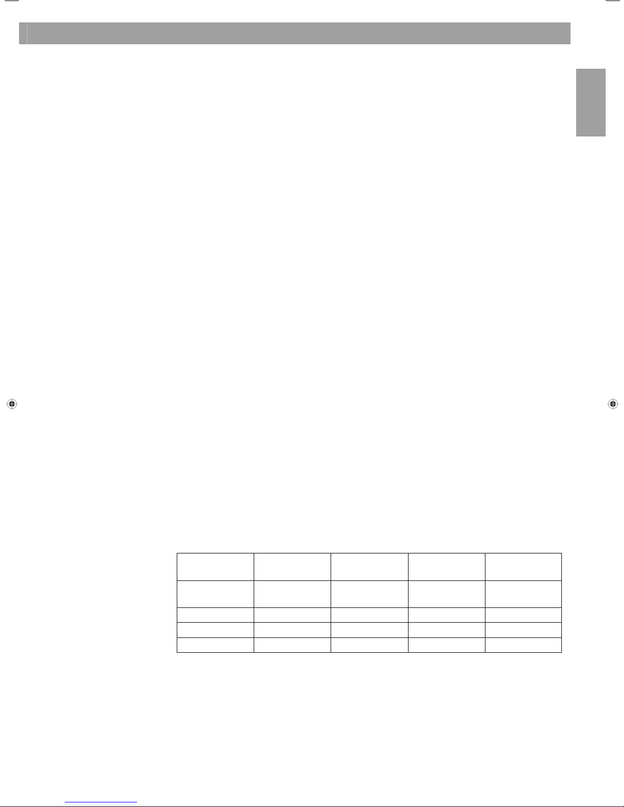
Electrical:
Power supply Power
consumption
Size
(H x W x D in mm)
Weight
CS AMS-8 90 - 264 Volt AC
(47-63Hz)
37 Watt maximum 88 x 485 285 4.5 kg
CS-WC 12 - 24 Volt DC 0.7 Watt maximum 80 x 115 x 48 0.12 kg
CS-LIM 24 Volt DC 1.5 Watt maximum 80 x 115 x 48 0.12 kg
CS-PP 12 - 24 Volt DC 1.7 Watt maximum 43 x 210 x 212 1.5 kg
Environmental:
Operating temperature: 0˚C up to 50˚C
Humidity: 80% relative humidity (without condensation)v
7. Technical specifications
24
English
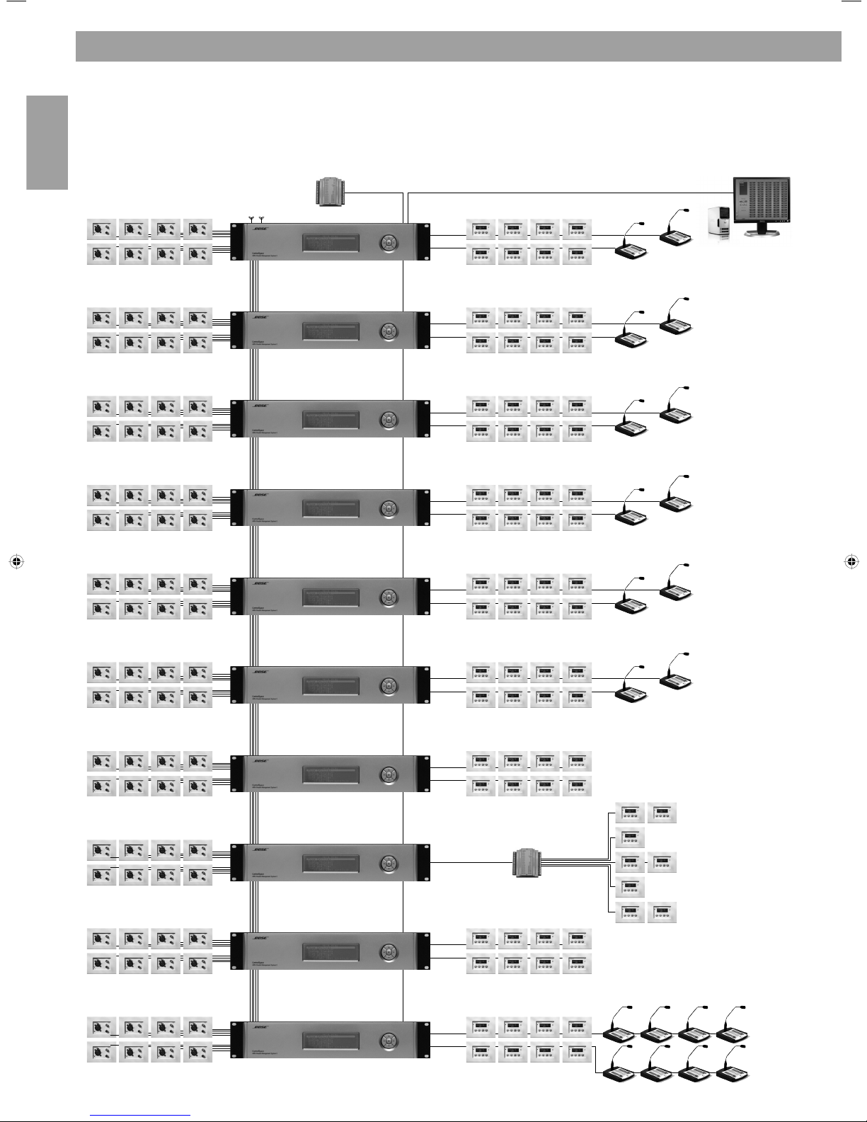
SCI
HUB
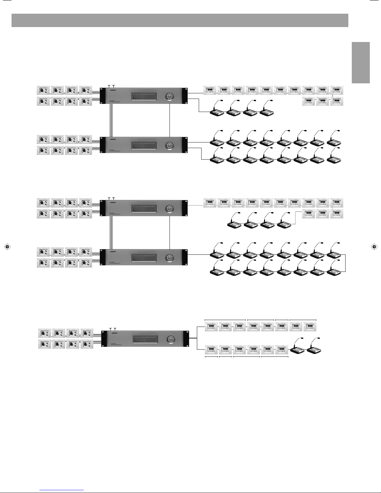
ControlSpace™ AMS-8 system with 80 zones
ANNEX A. ControlSpace™ AMS-8 system example
ANNEX A. ControlSpace™ AMS-8 system examples
English
25
ControlSpace™ AMS-8 system with multiple paging panels
ANNEX A. ControlSpace™ AMS-8 system example
ControlSpace™ AMS-8 system with multiple wall controllers in a single room
or
Zone 1 Zone 2 Zone 4Zone 3
Zone 5Zone 6 Zone 7 Zone 8
ANNEX A. ControlSpace™ AMS-8 system examples
26
English
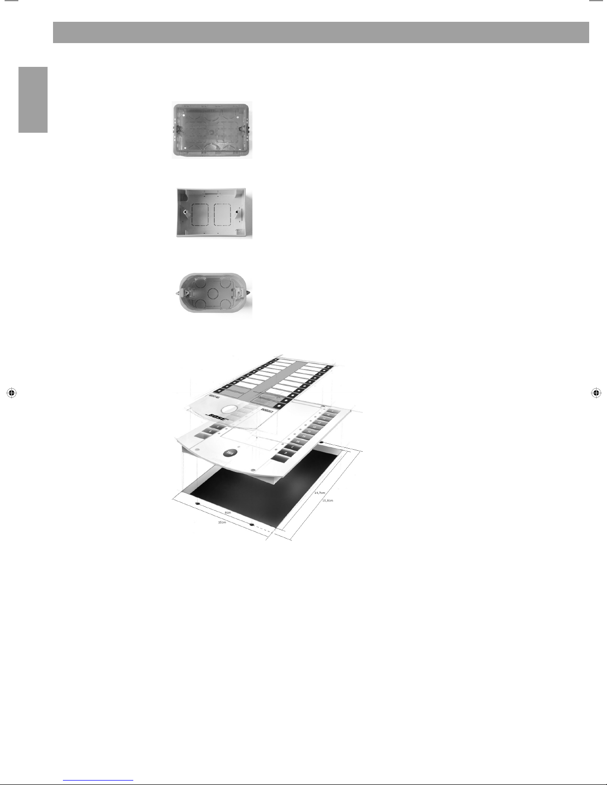
Flush mount box
The flush mount box is suitable for in-wall mounting of the ControlSpace
™
AMS-8
wall controller and ControlSpace AMS-8 local input module.
Dimensions (HxWxD): 7,1 x 10,6 x 5,2 cm
Surface mount box
The surface mount box is suitable for on-wall mounting of the ControlSpace™
AMS-8 wall controller and ControlSpace AMS-8 local input module.
Dimensions (HxWxD): 8,0 x 11,4 x 4,6 cm
Dry lining box for plasterboard walls
Dry lining box for hollow or plasterboards walls for in-wall mounting of the
ControlSpace™ AMS-8 wall controller and ControlSpace™ AMS-8 local input module.
Dimensions (HxWxD): 6,6 x 12,4 x 5,2 cm
Paging panel
Use these dimensions to mount the paging
panel into a desk or other. Mount a separate
XLR-connector (female) next to the paging panel,
which needs to be connected to the microphone
connection inside the paging panel. In order
to avoid any short circuit, remove the power
connection before mounting the paging panel.
ANNEX B. User Interface mounting instructions
ANNEX B. User Interface mounting instructions

English
27

28
English
How to reach the sales offices in Europe
Austria
Professional Systems Division, Austria
Bose Ges.m.b.H., Business Park Vienna
Wienerbergstrasse 7, 10 O.G.
1100 Wien, Österreich
Telephone: 01-60404340
Fax: 01-604043423
Belgium
Professional Systems Division, Belgium
Bose N.V., Limesweg 2
3700 Tongeren, België
Telephone: 012-390800
Fax: 012-390840
Denmark
Professional Systems Division, Denmark
Bose Danmark A/S, Industrivej 7
PO Box 14, 2605 Brøndby, Danmark
Telephone: 43437777
Fax: 43437818
France
Professional Systems Division, France
Bose S.A., 12 rue de Témara
78100 Saint Germain en Laye
Telephone: 01-30616363
Fax: 01-30616388
Germany
Professional Systems Division, Germany
Bose GmbH, Max-Planck-Straße 36,
61381 Friedrichsdorf, Deutschland
Telephone: 06172-7104-0
Fax: 06172-7104-19
Ireland
Professional Systems Division, Ireland
Bose GP, Castleblayney Road
Carrickmacross, County Monaghan
Republic Of Ireland
Telephone: 042-9661988,
Fax: 042-9661998
Italy
Professional Systems Division, Italy
Bose SpA, Via della Magliana 876
00148 Roma, Italia
Telephone: 066-5670802, Fax: 066-5680177
e-mail: bose_italy@bose.com
The Netherlands
Professional Systems Division, The Netherlands
Bose B.V., Nijverheidstraat 8
1135 GE Edam, Nederland
Telephone: 0299-390139
Fax: 0299-390109
Norway
Professional Systems Division, Norway
Bose Filial till Bose A/S Danmark, Lerkev 58
2209 Kongsvinger, Norge
Telephone: 062-821560
Fax: 062-821569
Switzerland
Professional Systems Division, Switzerland
Bose AG, Hauptstrasse 134
4450 Sissach, Sweiz
Telephone: 061-9757733
Fax: 061-9757744
Spain
Gaplasa S.A.
Avda. Ingeniero Conde de Torroja 25
28022 Madrid, España
Telephone: 91 748 29 60
Fax: 91 329 16 75
e-mail: bose@maygap.com
Sweden
Professional Systems Division, Sweden
Bose, filial till Bose A/S Danmark
Johannefredsgatan 4, 43153 Mölndal, Sverige
Telephone: 031-878850
Fax: 031-274891
United Kingdom
Professional Systems Division, United Kingdom
Bose Ltd., 1 Ambley Green
Gillingham Business Park
Gillingham, Kent ME8 0NJ, England
Telephone: 0870 -741-4500
Fax: 0870-741-4545
Poland
Bose Sp. z o.o.
Galeria Mokotów
ul. Wołoska 12
02-675 Warszawa
Telephone: (22) 852 2928
Fax: (22) 852 2927
European sales offices

English
29

Producenten forbeholder sig særlige rettigheder. Oplysningerne i denne vejledning kan ændres uden forudgående varsel og uden forpligtelser.
 Loading...