


Companion® 3 Series II Multimedia
Speaker System
Product Description
The Companion 3 series II multimedia speaker system is a stereo system designed to be used as a computer sound system. It can be used with any analog audio source. It has a bass module with a 6.5 inch dual voice coil woofer in a slot ported design. The two satellite speakers connect to the bass module and are mounted to speaker stands. The speakers can be placed on a desk or other surface when removed from the stands. A wired remote control pod is used to control volume and mute/un-mute functions. The system also has a second input and a stereo headphone output on the control pod.
©2007 Bose Corporation |
Service Manual |
Reference Number 297700-SM Rev. 05
Electronic copy only

Contents |
|
Safety Information ............................................................................................................................. |
3 |
Electrostatic Discharge Sensitive (ESDS) Device Handling ....................................................... |
3 |
Specifications.................................................................................................................................... |
4 |
Part List Notes .................................................................................................................................. |
5 |
Figure 1. Bass Module Assembly Exploded View .............................................................................. |
56 |
Bass Module Assembly Parts List ................................................................................................... |
6 |
Figure 2. Amplifier Module Assembly Exploded View........................................................................... |
7 |
Amplifier Module Assembly Parts list .............................................................................................. |
7 |
Figure 3. Packing Exploded Veiw ........................................................................................................ |
8 |
Packing Parts List ............................................................................................................................. |
8 |
Electrical Parts List .................................................................................................................... |
9-19 |
Main PCB Assembly Parts List................................................................................................... |
9-17 |
Power Supply PCB Assembly Parts List ................................................................................. |
18-19 |
Disassembly Procedures ......................................................................................................... |
20-22 |
Test Procedures ....................................................................................................................... |
23-25 |
Theory of Operation ................................................................................................................. |
26-28 |
Revision History ............................................................................................................................. |
29 |
Warranty
The Bose® Companion® 3 series II MultiMedia Speaker System is covered by a 1-year, transferable limited warranty.
Proprietary Information
THIS DOCUMENT CONTAINS PROPRIETARY INFORMATION OF BOSE CORPORATION WHICH IS BEING FURNISHED ONLY FOR THE PURPOSE OF SERVICING THE IDENTIFIED BOSE PRODUCT BY AN AUTHORIZED BOSE SERVICE CENTER OR OWNER OF THE BOSE PRODUCT, AND SHALL NOT BE REPRODUCED OR USED FOR ANY OTHER PURPOSE.
Caution: The Companion 3 series II MultiMedia Speaker System contains no user serviceable parts. To prevent warranty infractions, refer servicing to warranty service centers or factory service.
2

Safety Information
1.Parts that have special safety characteristics are identified by the  symbol on the schematics or by special notes on the parts list. Use only replacement parts that have critical characteristics recommended by the manufacturer.
2.Make leakage current or resistance measurements to determine that exposed parts are acceptably insulated from the supply circuit before returning the unit to the customer. Use the following checks to perform these measurements:
A.Leakage Current Hot Check- With the unit completely reassembled, plug the AC line cord directly into a 120V AC outlet. (Do not use an isolation transformer during this test). Use a leakage current tester or a metering system that complies with the American National Standards Institute (ANSI) C101.1 “Leakage Current for Appliances” and the Underwriters Laboratories (UL) 6500/IEC 60056 paragraph 9.1.1. With the unit AC switch first in the ON position and then in the OFF position, measure from a known earth ground (metal waterpipe, conduit, etc.) to all exposed metal parts of the unit (antennas, handle bracket, metal cabinet, screwheads, metallic overlays, control shafts, etc.) especially any exposed metal parts that offer an electrical return path to the chassis. Any current measured must not exceed 0.5 milliamp. Reverse the unit power cord plug in the AC outlet and repeat the test. ANY MEASUREMENTS NOT WITHIN THE LIMITS SPECIFIED HEREIN INDICATE A POTENTIAL SHOCK HAZARD THAT MUST BE ELIMINATED BEFORE RETURNING THE UNIT TO THE CUSTOMER.
B.Insulation Resistance Test Cold Check- (1) Unplug the power supply and connect a jumper wire between the two prongs of the plug. (2) Turn on the power switch of the unit. (3) Measure the resistance with an ohmmeter between the jumpered AC plug and each exposed metallic cabinet part on the unit. When testing 3 wire products, the resistance measured to the product enclosure should be between 2 and infinite MOhms. Also, the resistance measured to exposed input/output connectors should be between 4 and infinite MOhms. When testing 2 wire products, the resistance measured to exposed input/output connectors should be between 4 and infinite MOhms. If it is not within the limits specified, there is the possibility of a shock hazard, and the unit must be repaired and rechecked before it is returned to the customer.
Electrostatic Discharge Sensitive (ESDS)
Device Handling
This unit contains ESDS devices. We recommend the following precautions when repairing, replacing or transporting ESDS devices:
•Perform work at an electrically grounded work station.
•Wear wrist straps that connect to the station or heel straps that connect to conductive floor mats.
•Avoid touching the leads or contacts of ESDS devices or PC boards even if properly grounded. Handle boards by the edges only.
•Transport or store ESDS devices in ESD protective bags, bins, or totes. Do not insert unprotected devices into materials such as plastic, polystyrene foam, clear plastic bags, bubble wrap or plastic trays.
3
Specifications
Mechanical |
|
|
Dimensions: |
Bass Module: |
8 5/8 “ H x 7 1/8” W x 14” D |
|
|
(21.8 x 18 x 35.56 cm) |
|
Satellite Speaker: |
2 1/2” H x 2 3/4” W x 2 3/8” D |
|
(no stand) |
(6.14 x 6.86 x 6.03 cm) |
|
Control Pod: |
2 1/2 “ D x 1 1/8” H |
|
|
(6.35 x 2.79 cm) |
Weight: |
Bass Module: |
14.65 lbs (6.64 kg) unpacked |
|
Satellite Speaker: |
.75 lbs (0.34 kg) each |
|
Packaged System: |
20.15 lbs (9.13 kg) packed |
Finish: |
Bass Module: |
Scratch-resistant, satin-finish |
|
|
vinyl |
|
Satellites: |
Painted polymer finish |
Bass Box: |
|
Slot ported |
Bass Box Port Tuning: |
|
45 Hz |
Electrical |
|
|
Power Rating: |
USA/Canada: |
115 VAC 50/60 Hz |
|
Japan: |
100 VAC 50/60 Hz |
|
Euro: |
230 VAC 50/60 Hz |
Nominal System |
|
40 Hz to 15 kHz |
Bandwidth: |
|
|
Maximum SPL: |
|
100 dB (A weighted) pink |
|
|
noise signal |
Output: |
Bass: |
60 Watts |
|
Satellites: |
18 Watts per channel |
4
Part List Notes
1.This part is not normally available from Customer Service. Approval from the Field Service Manager is required before ordering.
2.The individual parts on the PCBs are listed in the Electrical Part list.
3. This part is critical for safety purposes. Failure to use a substitute replacement with the same safety characteristics as the recommended replacement part might create shock, fire and/or other hazards.
4. The part number listed is an assembly part number. The individual parts of the assembly might not be available separately.
5. This part is referenced for informational purposes only. It is not stocked as a repair part. Refer to the next higher assembly for a replacement part.
5
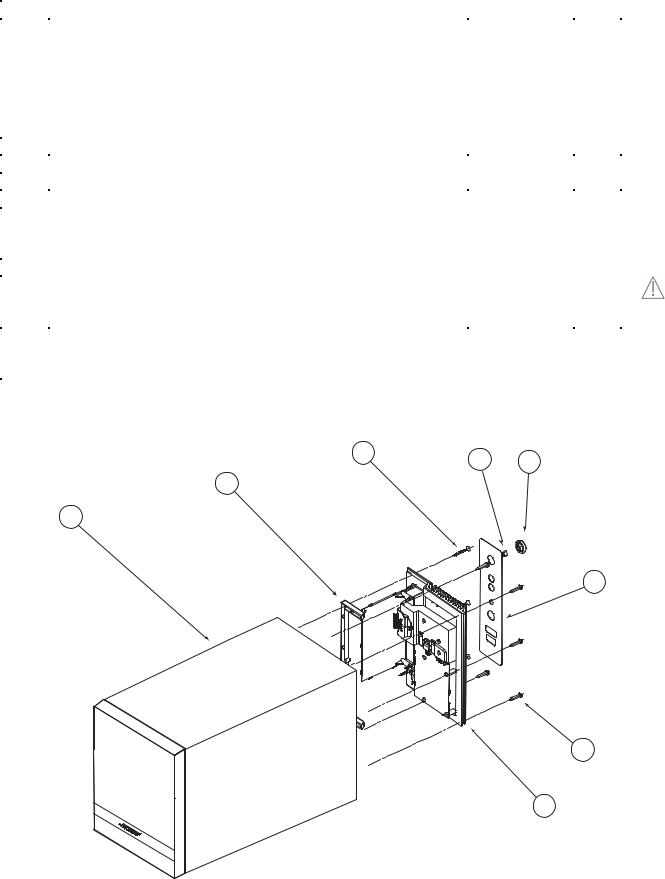
Bass Module Assembly Exploded View
Item |
Description |
Part Number |
Qty. |
Note |
1 |
BASS MODULE, ASSY, US/CANADA, 120V (Electrofoil Logo) |
*300905-001 |
1 |
|
|
BASS MODULE, ASSY, EURO, 230V (Electrofoil Logo) |
*300905-003 |
1 |
|
|
BASS MODULE, ASSY, JAPAN, 100V (Electrofoil Logo) |
*300905-002 |
1 |
|
|
BASS MODULE, ASSY, US/CANADA, 120V (Padprint Logo) |
*303939-112 |
|
|
|
BASS MODULE, ASSY, EURO, 230V (Padprint Logo) |
*303939-122 |
|
|
|
BASS MODULE, ASSY, JAPAN, 100V (Padprint Logo) |
*303939-132 |
|
|
|
(Complete bass module package, includes Amp Mod Assy) |
|
|
|
2 |
CLEAT, ABS |
271817-001 |
1 |
5 |
3 |
SCREW, 4 x 1, THDF, FLHD, 82 DEG, PH |
274151-16 |
3 |
|
4 |
CLIP, SPRING, KNOB |
262542 |
1 |
|
5 |
KNOB, VOL CNTL, BLK |
271860-001 |
1 |
|
6 |
LABEL, I/O, US/CANADA, 120V |
300954-001 |
1 |
|
|
LABEL, I/O, JAPAN, 100V |
300954-002 |
|
|
|
LABEL, I/O, EURO, 230V |
300954-003 |
|
|
7 |
SCREW, TF, 4 x 3/4, PAN, PH, BLK |
273556-12 |
5 |
|
8 |
MOD ASSY, AMP, 120V |
*307876-011 |
1 |
3 |
|
MOD ASSY, AMP, 220V, EURO |
*307876-033 |
1 |
|
|
|
|||
|
MOD ASSY, AMP, 100V JAPAN |
*307876-022 |
1 |
|
- |
XFORMER, TORROID, 105W, 15VDC, 7A |
271818-001 |
|
|
|
TRANSFORMER, TOROID, 100V, 60Hz |
N/A |
|
|
|
TRANSFORMER, TOROID, 230V, 50Hz |
277613-001 |
|
|
*Capacitor C7 on the new power supply board may need to be replaced, see Service Bulletin 271885-B4
3 |
X3 |
4 |
5 |
|
|
2
1
6
7 X5
8
Figure 1. Bass Module Assembly Exploded View
6
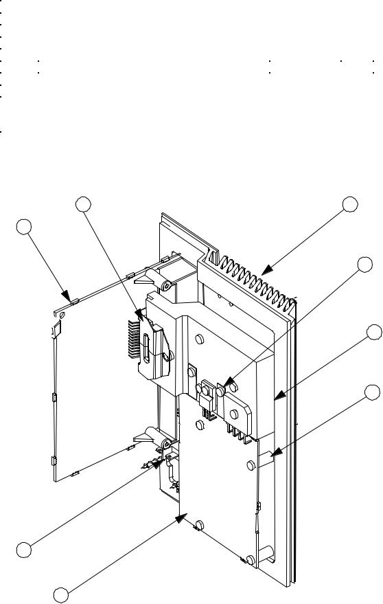
Amplifier Module Assembly
Item |
Description |
Part Number |
Qty. |
Note |
1 |
PCB ASSY, MAIN |
277574-001 |
1 |
5 |
2 |
BRACKET, METAL, IC |
271859 |
1 |
5 |
3 |
HEATSINK, EXTRUDED, COMP 3 |
271856 |
1 |
5 |
4 |
CLIP, THERMAL, THERMISTOR |
272964-001 |
1 |
5 |
5 |
HEAT SPREADER, ALUM |
279844-001 |
1 |
5 |
6 |
SCREW, TAPP, 6-13x.625, PAN, XRC/S |
172783-10 |
4 |
|
7 |
CONN, SWITCH, POWER, 3P |
273115-001 |
1 |
5 |
8 |
PCB ASSY, PS, 120V, US |
*307872-011 |
1 |
4 |
|
PCB ASSY, PS, 100V, JAPAN |
*307872-022 |
1 |
4 |
|
PCB ASSY, PS, 220V, EURO |
*307872-033 |
1 |
4 |
*Capacitor C7 on the new power supply board may need to be replaced, see Service Bulletin 271885-B4
2 |
3 |
1
4
5
6
7
8
Figure 2. Amplifier Module Assembly
7

Packaging Part List
Item |
Description |
Part |
Qty. |
Notes |
Number |
|
Number |
|
|
1 |
FEET, CLEAR SATELLITE |
178321-04 |
2 |
|
2 |
FEET, RUBBER, BRACKET |
260465 |
1 |
|
3 |
PACKING EPS, FILLER (includes both top and bottom filler) |
300908-001 |
1 |
|
4 |
CONTROL POD, (NON-REPAIRABLE) |
307874-002 |
1 |
|
5 |
CABLE, INPUT, 3.5MM, 6FT, BLK |
271994-001 |
1 |
|
6 |
LINE CORD, 100V, BLK, JAPAN |
264514-001 |
1 |
3 |
|
LINE CORD, 120V, BLK, US/CANADA |
262814-001 |
|
|
|
LINE CORD, 220V, BLK, EURO |
148203 |
|
|
|
LINE CORD, 230V, BLK, UK |
134725 |
|
|
|
LINE CORD, 240V, BLK, AUS |
284243-001 |
1 |
|
7 |
BASS MODULE, ASSY, US/CANADA, 120V (Electrofoil Logo) |
*300905-001 |
|
|
|
BASS MODULE, ASSY, EURO, 230V (Electrofoil Logo) |
*300905-003 |
|
|
|
BASS MODULE, ASSY, JAPAN, 100V (Electrofoil Logo) |
*300905-002 |
|
|
|
BASS MODULE, ASSY, US/CANADA, 120V (Padprint Logo) |
*303939-112 |
|
|
|
BASS MODULE, ASSY, EURO, 230V (Padprint Logo) |
*303939-122 |
|
|
|
BASS MODULE, ASSY, JAPAN, 100V (Padprint Logo) |
*303939-132 |
|
|
|
(Complete bass module package, includes Amp Mod Assy) |
300766-001 |
2 |
|
8 |
SAT, ASSY (Electrofoil Logo) |
|
||
|
SAT, ASSY (Padprint Logo) |
303938-002 |
|
|
|
(single array, includes speaker stand) |
296583 |
1 |
|
9 |
OWNERS GUIDE, 3 LANG, US/CANADA |
|
||
|
OWNERS GUIDE, 5 LANG, EURO |
296584 |
|
|
|
OWNERS GUIDE, 5 LANG, AP |
299450 |
|
|
10 |
CARTON, RSC, PRINTED |
300911-001 |
1 |
|
- |
CARTON KIT |
300911-001K |
1 |
|
*Capacitor C7 on the new power supply board may need to be replaced, see Service Bulletin 271885-B4 |
|
|||
|
4 |
|
|
|
|
5 |
|
|
|
1 |
|
9 |
|
|
|
|
|
|
|
2 |
|
|
|
|
3 |
6 |
|
|
|
|
|
|
|
|
10
3
7
8
Figure 3. Packaging Exploded View
8

ELECTRICAL PARTS LIST
Main PCB Assembly
Resistors
Reference |
Description |
Part Number |
Note |
Designator |
|
|
|
R101 |
1.21K, 0805, 1/10W, 1% |
133625-1211 |
|
R102 |
1.30K, 0805, 1/10W, 1% |
133625-1301 |
|
R103 |
9.53K, 0805, 1/10W, 1% |
133625-9531 |
|
R104 |
10.0K, 0805, 1/10W, 1% |
133625-1002 |
|
R105 |
127K, 0805, 1/10W, 1% |
133625-1273 |
|
R106 |
127K, 0805, 1/10W, 1% |
133625-1273 |
|
R107 |
10.0K, 0805, 1/10W, 1% |
133625-1002 |
|
R108 |
10.0K, 0805, 1/10W, 1% |
133625-1002 |
|
R109 |
2.00K, 0805, 1/10W, 1% |
133625-2001 |
|
R110 |
10.0K, 0805, 1/10W, 1% |
133625-1002 |
|
R111 |
10.0K, 0805, 1/10W, 1% |
133625-1002 |
|
R125 |
2.55K, 0805, 1/10W, 1% |
133625-2551 |
|
R126 |
200K, 0805, 1/10W, 1% |
133625-2003 |
|
R127 |
47.5K, 0805, 1/10W, 1% |
133625-4752 |
|
R128 |
1.10K, 0805, 1/10W, 1% |
133625-1101 |
|
R129 |
21.5K, 0805, 1/10W, 1% |
133625-2152 |
|
R130 |
330 OHM, 0805, 1/10W, 1% |
133625-3300 |
|
R131 |
6.81K, 0805, 1/10W, 1% |
133625-6811 |
|
R132 |
17.4K, 0805, 1/10W, 1% |
133625-1742 |
|
R133 |
1.62K, 0805, 1/10W, 1% |
133625-1621 |
|
R134 |
2.00K, 0805, 1/10W, 1% |
133625-2001 |
|
R135 |
1.00K, 0805, 1/10W, 1% |
133625-1001 |
|
R136 |
1.82K, 0805, 1/10W, 1% |
133625-1821 |
|
R137 |
10.0K, 0805, 1/10W, 1% |
133625-1002 |
|
R138 |
2.00K, 0805, 1/10W, 1% |
133625-2001 |
|
R139 |
1.50K, 0805, 1/10W, 1% |
133625-1501 |
|
R140 |
1.50K, 0805, 1/10W, 1% |
133625-1501 |
|
R201 |
1.21K, 0805, 1/10W, 1% |
133625-1211 |
|
R202 |
1.30K, 0805, 1/10W, 1% |
133625-1301 |
|
R203 |
9.53K, 0805, 1/10W, 1% |
133625-9531 |
|
R204 |
127K, 0805, 1/10W, 1% |
133625-1273 |
|
R205 |
10.0K, 0805, 1/10W, 1% |
133625-1002 |
|
R206 |
127K, 0805, 1/10W, 1% |
133625-1273 |
|
R207 |
10.0K, 0805, 1/10W, 1% |
133625-1002 |
|
R208 |
10.0K, 0805, 1/10W, 1% |
133625-1002 |
|
R209 |
10.0K, 0805, 1/10W, 1% |
133625-1002 |
|
R210 |
10.0K, 0805, 1/10W, 1% |
133625-1002 |
|
R211 |
2.00K, 0805, 1/10W, 1% |
133625-2001 |
|
R225 |
100K, 0805, 1/10W, 1% |
133625-1003 |
|
R226 |
100K, 0805, 1/10W, 1% |
133625-1003 |
|
R227 |
JUMPER, CHIP, 0805 |
133627 |
|
R229 |
2.55K, 0805, 1/10W, 1% |
133625-2551 |
|
R230 |
200K, 0805, 1/10W, 1% |
133625-2003 |
|
R231 |
47.5K, 0805, 1/10W, 1% |
133625-4752 |
|
R232 |
1.10K, 0805, 1/10W, 1% |
133625-1101 |
|
9
 Loading...