


Contents |
|
Safety Information ............................................................................................................................ |
2 |
Electrostatic Discharge Sensitive (ESDS) Device Handling ......................................................... |
2 |
Specifications ................................................................................................................................ |
3-5 |
Theory of Operation ................................................................................................................... |
6-28 |
Disassembly/Assembly ............................................................................................................ |
29-30 |
Setting-up a Computer to Issue TAP Commands ........................................................................ |
31 |
Issuing TAP Commands to the AV28 media center ..................................................................... |
32 |
General Test Procedure Notes ....................................................................................................... |
32 |
Functional/Performance Verification Tests ............................................................................. |
33-34 |
Adjustment/Performance Verification Procedures ................................................................ |
35-37 |
Figure 1. AM Test Setup .................................................................................................................... |
35 |
Figure 2. Tap Test Cable Part Number 264565 .................................................................................. |
38 |
Part List Notes ................................................................................................................................. |
38 |
Main Part List ................................................................................................................................... |
39 |
Figure 3. Exploded View .................................................................................................................... |
40 |
Main PCB 260318-0 Electrical Part List ................................................................................... |
41-55 |
Tuner PCB 260322-1 Electrical Part List ................................................................................. |
56-60 |
Head Unit Packaging Part List ....................................................................................................... |
61 |
Figure 4. Console Packaging ............................................................................................................ |
61 |
Figure 6. Laser Current Measurement Point...................................................................................... |
62 |
Figure 5. DVD Player Rear Panel ...................................................................................................... |
62 |
Laser Current Measurement .......................................................................................................... |
62 |
Integrated Circuit Diagrams ..................................................................................................... |
63-67 |
Changing House Codes ................................................................................................................. |
68 |
Figure 7. House Code Settings ......................................................................................................... |
68 |
Zone 2 Operation ............................................................................................................................ |
69 |
Figure 8. Zone 2 Remote Control Switch Setting .............................................................................. |
69 |
Console-Key Special Function Features ...................................................................................... |
70 |
Software Update Information
The software in the AV28 Media center can be updated using a software update CD available from Bose® service. Refer to procedure 2 on page 70, Console-Key Special Function Features, to determine the software version of the unit. Contact Bose Service or refer to the Bose service extranet site for information regarding the latest software revision; click on Lifestyle® music centers and then AV28 media center. http://serviceops.bose.com
PROPRIETARY INFORMATION
THIS DOCUMENT CONTAINS PROPRIETARY INFORMATION OF
BOSE CORPORATION WHICH IS BEING FURNISHED ONLY FOR
THE PURPOSE OF SERVICING THE IDENTIFIED BOSE PRODUCT
BY AN AUTHORIZED SERVICE CENTER OR OWNER OF THE
BOSE PRODUCT, AND SHALL NOT BE REPRODUCED OR USED
FOR ANY OTHER PURPOSE.
1

SAFETY INFORMATION
1.Parts that have special safety characteristics are identified by the symbol on  schematics or by special notes on the parts list. Use only replacement parts that have critical characteristics recommended by the manufacturer.
2.Make leakage current or resistance measurements to determine that exposed parts are acceptably insulated from the supply circuit before returning the unit to the customer. Use the following checks to perform these measurements:
A.Leakage Current Hot Check-With the unit completely reassembled, plug the AC line cord directly into a 120V AC outlet. (Do not use an isolation transformer during this test.) Use a leakage current tester or a metering system that complies with American National Standards Institute (ANSI) C101.1 “Leakage Current for Appliances” and Underwriters Laboratories (UL) 6500 IEC 60065 paragraph 9.1.1. With the unit switch first in the ON position and then in OFF position, measure from a known earth ground (metal water-pipe, conduit, etc.) to all exposed metal parts of the unit (antennas, handle bracket, metal cabinet, screw-heads, metallic overlays, control shafts, etc.), especially any exposed metal parts that offer an electrical return path to the chassis. Any current measured must not exceed 0.5 milliamp. Reverse the unit power cord plug in the outlet and repeat test. ANY MEASUREMENTS NOT WITHIN THE LIMITS SPECIFIED HEREIN INDICATE A POTENTIAL SHOCK HAZARD THAT MUST BE ELIMINATED BEFORE RETURNING THE UNIT TO THE CUSTOMER.
B.Insulation Resistance Test Cold Check-(1) Unplug the power supply and connect a jumper wire between the two prongs of the plug. (2) Turn on the power switch of the unit. (3) Measure the resistance with an ohmmeter between the jumpered AC plug and each exposed metallic cabinet part on the unit. When the exposed metallic part has a return path to the chassis, the reading should be between 2 and 5.2 Megohms. When testing 3 wire products, the resistance measured to the product enclosure should be between 2 and infinite Meg ohms. Also, the resistance measured to exposed output/input connectors should be between 4 and infinite Meg ohms. When testing 2 wire products, the resistance measured to exposed output/input connectors should be between 4 and infinite Meg ohms. If it is not within the limits specified, there is the possibility of a shock hazard, and the unit must be repaired and rechecked before it is RETURNED TO THE CUSTOMER.
ELECTROSTATIC DISCHARGE SENSITIVE (ESDS) DEVICE HANDLING
This unit contains ESDS devices. We recommend the following precautions when repairing, replacing or transporting ESDS devices:
•Perform work at an electrically grounded work station.
•Wear wrist straps that connect to the station or heel straps that connect to conductive floor mats.
•Avoid touching the leads or contacts of ESDS devices or PC boards even if properly grounded. Handle boards by the edges only.
•Transport or store ESDS devices in ESD protective bags, bins, or totes. Do not insert unprotected devices into materials such as plastic, polystyrene foam, clear plastic bags, bubble wrap or plastic trays.
2

Specifications |
|
|
|
Physical Description: |
|
Dimensions: |
15.8" W x 11.0" D x 3.5" H (40.1 x 27.9 x 8.9 cm) |
Weight: |
8.2 lbs. (3.7 kg) |
Cover: |
Aluminum |
Base: |
Molded plastic |
Display: |
Vacuum fluorescent |
Inputs: |
|
TAPE: |
2 Vrms, maximum |
AUX: |
2 Vrms, maximum |
VCR: |
2 Vrms, maximum |
TV: |
2 Vrms, maximum |
Digital: |
S/PDIF (1 each for TV, VCR, TAPE, and AUX) |
Composite video: |
NTSC or PAL format 1Vpp with sync 75 Ohm |
S-Video: |
Luminance 1Vpp, chrominance 0.3Vpp |
Component video: |
NTSC or PAL 1Vpp with sync on Y |
Optical input: |
S/PDIF digital, mapped to input |
FM antenna: |
75 Ohm |
AM antenna: |
12uH |
TV sensor: |
NTSC/PAL/HDTV/480p compatible |
Power: |
33 Vdc, 2.1mm jack, provided by DCS91 power pack |
Serial data port: |
3.5mm miniature stereo jack, data in/out |
Remote control receiver: |
RF or IR, user selectable |
Outputs: |
|
Speaker Zone 1: |
S/PDIF and variable analog |
Speaker Zone 2: |
S/PDIF and variable analog |
Record L and R: |
Fixed audio |
Record digital: |
S/PDIF and Optical |
Optical output: |
S/PDIF, -15 to -21 dBm |
Composite video: |
NTSC or PAL 1Vpp with sync 75 Ohm |
S-Video: |
Luminance 1Vpp, Chrominance 0.3Vpp |
IR: |
Controls other manufacturer's IR operated devices, |
|
universal method |
FM Tuner: |
|
Tuning range: |
87.7 MHz-107.9 MHz |
De-emphasis: |
75 usec |
Channel spacing: |
200 kHz |
Sensitivity, mono usable: |
13 dBf |
Stereo, 50 dB quieting: |
38 dBf |
Signal-to-noise @ 65 dBf: |
Mono: 74 dBf, Stereo: 70 dBf |
Noise ratio @ 65 dBf: |
Mono: 85, Stereo: 85 |
Harmonic distortion, 1 kHz, @ 65dBf |
Mono: 0.3%, Stereo: 0.4% |
Capture ratio @ 45 dBf: |
2.0 dB |
AM rejection @ 45 dBf: |
60 dB |
Adjacent channel selectivity, 200 kHz, |
13 dB |
for both channels, @ 45 dBf: |
|
Alternate channel selectivity, 400 kHz, |
70 dB |
for both channels, @ 45 dBF: |
|
Image rejection: |
45 dB |
RF inter-modulation: |
65 dB |
Sub-carrier product rejection @ 65 dBf: |
55 dB |
Frequency response 30 Hz-15 kHz: |
+1.0 dB |
Stereo channel separation @ 1 kHz: |
35 dB |
Auto stop level (seek): |
30 dBf |
Mono/Stereo threshold: |
40 dBf |
3

Specifications
AM Tuner:
Channel spacing: |
|
|
|
|
10 kHz |
|
|
|
|
|
|
|
|
|
||||
|
|
|
|
|
|
|
|
|
|
|
|
|
|
|
|
|
|
|
|
Test Parameter |
|
Condition |
|
|
530- |
560- |
600- |
|
710- |
960- |
1410- |
|
1620- |
|
|||
|
|
|
|
|
|
|
550 |
590 |
700 |
|
950 |
1400 |
1610 |
|
1710 |
|
||
|
|
|
|
|
|
|
kHz |
|
kHz |
kHz |
kHz |
kHz |
kHz |
|
kHz |
|
||
|
Usable |
|
Nominal |
|
|
55 |
52 |
50 |
|
49 |
48 |
47 |
|
47 |
|
|||
|
Sensitivity1, |
|
Ambient |
|
|
61 |
57 |
55 |
|
55 |
53 |
52 |
|
52 |
|
|||
|
dBuV/m |
|
Limit |
|
|
|
|
|
|
|
|
|
|
|
|
|
|
|
|
|
|
Environmental |
|
67 |
63 |
61 |
|
60 |
59 |
58 |
|
58 |
|
||||
|
|
|
Limit |
|
|
|
|
|
|
|
|
|
|
|
|
|
|
|
|
Adjacent |
|
Nominal |
|
|
26 |
26 |
27 |
|
23 |
23 |
25 |
|
22 |
|
|||
|
Channel |
|
Ambient Limit |
|
|
21 |
21 |
22 |
|
18 |
18 |
20 |
|
17 |
|
|||
|
Selectivity2, dB |
|
|
|
|
|
|
|
|
|
|
|
|
|
|
|
|
|
|
Alternate |
|
Nominal |
|
|
30 |
30 |
30 |
|
30 |
30 |
29 |
|
27 |
|
|||
|
Channel |
|
Ambient Limit |
|
|
25 |
25 |
25 |
|
25 |
25 |
24 |
|
22 |
|
|||
|
Selectivity2, dB |
|
|
|
|
|
|
|
|
|
|
|
|
|
|
|
|
|
|
Image |
|
Nominal |
|
|
35 |
37 |
40 |
|
40 |
40 |
40 |
|
40 |
|
|||
|
Rejection |
|
Ambient Limit |
|
|
30 |
32 |
35 |
|
35 |
35 |
35 |
|
35 |
|
|||
|
Ratio, dB |
|
|
|
|
|
|
|
|
|
|
|
|
|
|
|
|
|
|
Signal to Noise |
|
Nominal |
|
|
50 |
50 |
50 |
|
50 |
50 |
50 |
|
50 |
|
|||
|
Ratio, dB |
|
Ambient Limit |
|
|
45 |
45 |
45 |
|
45 |
45 |
45 |
|
45 |
|
|||
|
|
|
Environmental |
|
40 |
40 |
40 |
|
40 |
40 |
40 |
|
40 |
|
||||
|
|
|
Limit |
|
|
|
|
|
|
|
|
|
|
|
|
|
|
|
|
Distortion, % |
|
Nominal |
|
|
0.6 |
0.6 |
0.6 |
|
0.6 |
0.6 |
0.6 |
|
0.6 |
|
|||
|
|
|
Ambient |
|
|
1.4 |
1.4 |
1.4 |
|
1.4 |
1.4 |
1.4 |
|
1.4 |
|
|||
|
|
|
Limit |
|
|
|
|
|
|
|
|
|
|
|
|
|
|
|
|
|
|
Environmental |
|
2.0 |
2.0 |
2.0 |
|
2.0 |
2.0 |
2.0 |
|
2.0 |
|
||||
|
|
|
Limit |
|
|
|
|
|
|
|
|
|
|
|
|
|
|
|
|
Frequency |
|
Nominal |
|
|
-3 |
-3 |
-3 |
|
-3 |
-3 |
-3 |
|
-3 |
|
|
||
|
Response, dB |
|
Ambient Limit |
|
|
-6 |
-6 |
-6 |
|
-6 |
-6 |
-6 |
|
-6 |
|
|
||
|
@ 220 Hz, 2.0 |
|
|
|
|
|
|
|
|
|
|
|
|
|
|
|
|
|
|
kHz |
|
|
|
|
|
|
|
|
|
|
|
|
|
|
|
|
|
|
Auto Stop |
|
|
|
|
|
70 ± 7 |
65 ± 7 |
63 ± 7 |
|
60 ± 7 |
54 ± 7 |
48 ± 7 |
|
48 ± 7 |
|
||
|
Level, dBuV/m |
|
|
|
|
|
|
|
|
|
|
|
|
|
|
|
|
|
|
|
|
|
|
|
|
|
|
|
|
|
|
|
|
|
|
||
Single disc CD/DVD: |
|
|
|
|
|
|
|
|
|
|
|
|
|
|
||||
Supported formats: |
|
|
|
|
DVD video, Audio CD, CD-R, CD-R/W, MP3 CD |
|
|
|
||||||||||
CD performance: |
|
|
|
|
|
|
|
|
|
|
|
|
|
|
|
|
||
|
|
|
|
|
|
|
|
|
|
|
|
|||||||
|
Parameter |
|
Nominal |
|
Limit |
|
|
Test Disc |
|
|
|
|||||||
|
Defect Tracking (void) |
|
|
1.0 mm |
|
0.8 mm |
|
ABEX test disc TCD-725A |
|
|
|
|||||||
|
Defect Tracking (black dot) |
|
|
1.0 mm |
|
0.8 mm |
|
ABEX test disc TCD-725R |
|
|
|
|||||||
|
Defect Tracking (scratch) |
|
|
1.6 mm |
|
1.0 mm |
|
ABEX test disc TCD-721 R |
|
|
|
|||||||
|
Defect Tracking |
|
|
75 mm |
|
65 mm |
|
ABEX test disc TCD-725R |
|
|
|
|||||||
|
(finger print) |
|
|
|
|
|
|
|
|
|
|
|
|
|
|
|
||
|
Defect Tracking |
|
|
1.0 mm |
|
0.7 mm |
|
ABEX test disc TCD-732RA |
|
|
|
|||||||
|
(warped disc) |
|
|
|
|
|
|
|
|
|
|
|
|
|
|
|
||
|
Defect Tracking |
|
|
210 mm |
|
140 mm |
|
ABEX test disc TCD-714R |
|
|
|
|||||||
|
(eccentric disc) |
|
|
|
|
|
|
|
|
|
|
|
|
|
|
|
||
|
Cueing Time |
|
|
|
2 sec |
|
3 sec |
|
Phillips TS4, tracks 1-15 |
|
|
|
||||||
4

|
Specifications |
|
|
Analog Inputs: |
|
Input level: |
Full scale output; 2 Vrms maximum, 200 mVrms |
Input impedance: |
33 k |
Input coupling: |
AC coupled |
Analog Outputs: |
|
Output level: |
2 Vrms |
Output level from FM: |
0.6 Vrms |
Output level from AM: |
0.4 Vrms |
Source impedance @ 1 kHz: |
220 Ohms |
Load impedance: |
10 k, 2 k minimum |
Output coupling: |
AC coupled |
Headphone Jack: |
|
Connector: |
Mini stereo jack |
Output level: |
31 mW at THD <0.15% into a 32 Ohm load |
Electrical S/PDIF Input: |
|
Sampling rates accommodated: |
32 kHz, 44.1 kHz, 48 kHz |
Bits recognized and accepted: |
16, 20, 24 |
Input impedance: |
75 Ohms |
Input coupling: |
AC coupled |
Optical S/PDIF Input: |
|
Sampling rates accommodated: |
32 kHz, 44.1 kHz, 48 kHz |
Bits recognized and accepted: |
16, 20, 24 |
Connector: |
TOSLINK |
Electrical/Optical S/PDIF Output: |
|
Sampling rates accommodated: |
32 kHz, 44.1 kHz, 48 kHz |
Protocol: |
SDMI (Secure Digital Music Initiative) |
Remote Control: |
|
Range: |
65 ft (20m) |
RF frequency: |
27.145 MHz |
5
Theory of Operation
1.0 Overview
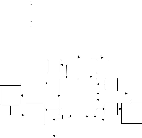
The AV28 media center is a self-contained DVD/CD/MP3 disc player with an AM/FM tuner for use with Bose® powered speaker systems. In addition to the two internal sources (DVD/CD and AM/ FM tuner), it allows playing up to four external audio sources: TV, VCR, AUX, and TAPE. A 27MHz, one-way RF remote control operates the unit without line-of-sight restriction; provisions for infrared remote control of the media center also exist. An integrated IR Blaster allows limited control of other manufacturer’s equipment (TV’s, VCR’s and Cable/Satellite Set-Top boxes). The AV28 media center has two independent audio output zones, accessible through circular DIN connectors in the back of the product.
The AV28 media center contains five PCBs:
PCB |
Assembly P/N |
Main PCB |
260318-0 |
IR PCB |
Part of 260318-0 |
Headphone PCB |
Part of 260318-0 |
Tuner PCB |
260322-1 |
Keypad PCB |
254141 |
There are some components shown on schematics whose reference designators end in –NV; these components are not loaded by manufacturing, but their pads exist on the PCB.
VFD |
|
DRAM |
|
|
|
|
|
|
|
|
|
|
|
|
DVD ROM |
|
|
|
|
|
Flash |
||
|
|
|
Drive |
|
|
|
ATAPI |
|
|
|
|
|
|
|
|
|
|
|
|
|
|
||
|
|
|
|
|
|
|
|
|
|
||
Video Path |
|
|
|
|
|
|
|
|
|
|
|
|
|
|
|
|
|
||||||
|
|
|
|
|
|
|
|
|
|
||
|
|
|
|
|
|
|
|
|
|
|
|
|
|
|
|
|
|
|
|
|
|
TV Power |
|
|
|
|
|
|
|
|
|
|
|
Dongle |
|
|
|
|
|
|
|
|
|
|
|
||
|
|
|
|
|
|
|
|
|
|
|
|
AM / FM |
|
U1 |
|
|
|
|
|
|
|
|
|||
|
|
|
|
|
|
|
CCB Bus |
CS9800 |
|
|
ETAP |
||
Tuner |
|
|
||||
|
DVD Decoder IC |
Power Fail |
||||
|
|
|||||
Power
Supply
Audio Path Synch Power
Supply
|
|
|
|
|
|
|
|
|
|
|
|
|
|
|
|
|
|
|
|
|
|
|
|
|
|
UEI |
|
IR |
|
Console |
|
|
|
|
|
|||
Blaster IC |
|
Receiver |
|
Buttons |
|
|
RF Remote |
|||||
|
|
|
|
|
|
|
|
|
|
XCVR |
||
|
|
|
|
|
|
|
|
|
|
|
|
|
|
|
|
|
|
|
|
|
|
|
|
|
|
|
|
|
|
|
|
|
|
|
|
|
|
|
IR Blaster |
|
|
|
|
|
|
|
|
|
|
|
|
Board |
|
|
|
|
|
|
|
|
|
|
|
|
|
|
|
|
|
|
|
|
|
|
|
|
|
Block Diagram
6
Theory of Operation
2.0Power Supply Electronics
2.1Architecture
Voltage |
Type |
PCB Location |
Input |
Outputs |
|
|
(schematic page) |
|
|
+33 |
Linear |
Power Pack |
120VAC |
+12V, +5.1V, +3.3V |
+12 |
Switching |
Tuner (3) |
V_RAW |
DVD drive, VFD, +10V |
+10 |
Linear |
Tuner (3) |
+12 |
Tuner, Transceiver, Audio path, +8V |
+8 |
Linear |
Main (9) |
+10 |
Video circuits |
+5.1 |
Switching |
Main (9) |
V_RAW |
DVD drive, Audio path, +3.3 |
+3.3 |
Switching |
Main (9) |
V_RAW |
Flash, DRAM, U1 I/O & core, misc. logic |
+2.5 |
Linear |
Main (9) |
+3.3 |
U1 PLL circuits |
V_RAW is provided to the console by an external power pack and is approximately 33VDC. The power pack is a linear transformer. In addition to the usual large capacitor and full-bridge diode rectifier, a PTC thermistor (effectively a reset-able fuse) is contained in the power pack to protect the unit under fault conditions. V_RAW enters the console on the tuner PCB, passes through an NTC thermistor to eliminate power supply startup surges, and is fed to the +12V supply and the flat-flex cable, which feeds it to the +5.1V and +3.3V supplies on the Main PCB.
|
|
|
|
|
|
|
+12V |
|
|
+10V |
|
|
+8V |
|
|
|
|
|
|
|
SMPS |
|
|
Linear |
|
|
Linear |
|
|
|
|
|
|
|
|
|
|
|
|||
|
|
|
|
|
|
|
|
|
|
|
|
|
|
|
|
|
|
|
|
|
|
|
|
|
|
|
|
AC line |
|
DCS |
+33V |
|
+5.1V |
|
|
|
|
|
|
||
voltage |
|
|
9X |
|
|
|
SMPS |
|
|
|
|
|
|
|
|
|
|
|
|
|
|
|
|
||||
from wall |
|
Linear |
|
|
|
|
|
|
|
|
|
|
|
|
|
|
|
|
|
|
|
|
|
|
|
|
|
|
|
|
|
|
|
|
|
|
|
|
|
|
|
|
|
|
|
|
|
|
+3.3V |
|
|
+2.5V |
|
|
|
|
|
|
|
|
|
|
SMPS |
|
|
Linear |
|
|
|
|
|
|
|
|
|
|
|
|
|
|
|
||
|
|
|
|
|
|
|
|
|
|
|
|
|
|
Power Supply Block Diagram
2.2 Switching Power Supplies
See SD254135 sheet 9 and SD256131 sheet 3 for the power supply circuits.
The switching power supplies are ST L4973D3.3 regulator ICs (U802 and U803 on the Main PCB, and U301 on the Tuner PCB). The power supplies are designed as step-down Buck converters. The voltage fed back to the chip on pin 13 determines the output voltage; the chip’s control circuitry will work to keep this voltage at +3.3V. The +5.1V and +12V supplies use resistor divide-down networks to obtain the +3.3V feedback voltage.
The reference designators discussed in this section correspond to the +12V regulator on the tuner board; the designs of the +5.1V and +3.3V regulators are nearly identical. A number of additional components exist to provide filtering functions.
7

Theory of Operation
IC Pin |
Components Connected |
Pin Function |
1 |
R301, C302, C303 |
Sets switching frequency (when not controlled |
|
|
externally) |
10 |
C308 |
Drives internal D-MOS |
11 |
R322 |
Inhibits supply |
12 |
R302, C305, C307 |
Lead-lag filter for compensation loop |
13 |
R304, R305 |
Voltage feedback for control |
18 |
C304 |
+5.1V for external reference |
19 |
C306 |
Sets supply soft-start time constant |
20 |
None |
Supply frequency switching synchronization |
|
|
(see note) |
2.3 Supply Synchronization Generator
To limit radiated noise, all three switching supplies (12V, 5V and 3.3V) are synchronized to the same control frequency. This frequency is varied by U1, as needed, to keep noise out of the AM tuner.
U805 is a 74HC592 8-bit binary counter IC with an input register. An 11.2896 MHz clock signal is fed to the counter clock (CCK) pin, and the chip counts on positive edges of this signal. Inputs A through H are loaded to the register on positive edges of the register clock (RCK) signal, and the register outputs are loaded to the counter when the active-low counter load (/CLOAD) is asserted. These two signals are driven by the chip’s own active-low ripple carryout (/RCO), which is also the output to the level shifter circuit. The active-low counter clock enable (/CCKEN) is pulled low by a 100 Ohm resistor, and the active-low asynchronous counter clear (/CCLR) is tied to the Main PCB’s hardware reset line. The /RCO output is fed to a level shifter circuit (Q801 and Q804).
The synchronization clock is fed to all three switching power supply regulators in the console. The clock frequency will be either 98.1704 kHz or 101.7081 kHz, depending on the state of SUPPLY_FREQ_SEL, driven by U1. U1 picks the state based on AM tuner frequency.
2.4 Power Fail Detection
Q802 and Q803 detect a power failure by asserting the active-low /POWER_FAIL signal when the console input voltage V_RAW falls below a given threshold (equivalent to an AC line voltage of about 75 VACRMS). This signal is fed to U1 as an interrupt so the micro can perform some shutdown functions before it is held in reset; see section 3.1.2 for additional information.
2.5 Grounding
R321 on the Tuner PCB connects PGND (the ground provided to the product by the power pack) and GND (tuner signal ground). The power supply ground on the Main PCB is connected to GND only at C832 and C828.
Additional signal ground connections between the Main and Tuner PCBs and between the PCBs and the conductive paint on the plastics are made by conductive gasket material attached to the plastic cover and base.
8
Theory of Operation
2.6 Troubleshooting
Verifying functionality of the power supply system by measuring the DC levels on each supply (including the power pack) is sufficient for basic troubleshooting.
If power supply problems are suspected, or if DC levels on the supplies are incorrect, evaluate and correct these parameters with no power applied:
•Check continuity between J104 and pin 8 of each supply.
•Measure the resistance of R321 on the Tuner PCB.
•Measure the resistance of feedback resistors (R304 and R305 in the +12V supply) in each supply.
•Verify that no supply voltage output is shorted to ground.
3.0 Control Electronics
The majority of the control electronics are located on the Main PCB, the notable exceptions being the Infrared Blaster diodes and receiver module (located on an auxiliary PCB under the DVD-ROM drive tray) and the RF transceiver circuitry (located on the Tuner PCB).
3.1 Processor
U1 is a CS98000 DVD decoder IC that also functions as the media center’s main processor.
U1 contains two built-in 32-bit RISC processors, a DSP core, a memory interface which supports SDRAM and FLASH ROM, an ATAPI interface, a DMA controller, an MPEG video decoder, onboard data and instruction caches, a digital video interface, digital audio processing, a general purpose interface, and numerous general-purpose I/O.
One RISC processor in U1 (RISC0) manages the ATAPI interface to the DVD-ROM drive, and handles all low-level details associated with playback/navigation of DVD and CD discs. RISC0 sends standard ATAPI control commands to the drive and receives MPEG-compressed audio, video, and control information back. It decodes the MPEG information from the DVD-ROM drive on the ATAPI bus and stores the decoded video into SDRAM for later readout to the video interface. It also oversees the onboard DSP core, as required, when decoding digital audio data, and sends it out the digital audio interfaces.
The second RISC processor (RISC1) runs Bose® software that handles system control, assembles VFD and On-Screen Display (OSD) information, and controls I/O functions including reading the console buttons, receiving the RF and IR remote control commands, driving the OSD and VFD display on the console, controlling the AM/FM tuner sub-circuit, and driving the IR blaster controls.
Connections to U1 are made throughout SD254135.
9
Theory of Operation
3.1.1 Processor Clock
U1 is clocked by a crystal inverter-oscillator whose nominal frequency is 27 MHz.
A 10KW resistor (R713) biases one gate of U701, a 74VHCU04 [high-speed, unbuffered] inverter. The crystal in the inverter’s feedback path is designed for a 22pF load, achieved by the series combination of the two 30pF load capacitors C704 and C707 and other stray capacitance in the input gates of U1. R714 sets the pole in the oscillator’s loop response, and R715 buffers the output between the oscillator and U1. See sheet 8 of SD254135.
After the signal is buffered by U1, the 27 MHz clock drives the video circuitry. Frequency accuracy within ±50ppm of this oscillator circuit is necessary for color video operation.
3.1.2Processor Reset
U703 generates a 140ms reset pulse at power-on and any time the +3.3V supply dips below 2.93 volts (corresponding to an AC line voltage of about 40VACRMS. The pulse is buffered by two of the gates of U701, a 74VHCU04 inverter, and distributed as active-low /RESET1. The reset signal ensures reliable startup of U1 at power-up and after a brownout.
See the comments in section 2.4 regarding power-fail detection.
3.2 Memory
See sheet 1 of SD254135.
The U1 memory interface supports both SDRAM and flash memory of various sizes. Both memory ICs are connected to the same bus, and a chip select chooses between the two devices. The type of memory cycle that is run depends on which address space is needed.
3.2.1 FLASH
U2 is a 1-megaword by 16-bit Flash memory IC. FLASH memory is nonvolatile, meaning that its stored data is not lost when the chip loses power. The FLASH is used to store all application software for the product (including software to run on both of U1’s RISC processors and its DSP). This software is programmed into the FLASH by Manufacturing during In-Circuit Test. The FLASH also stores nonvolatile user parameters, such as AM/FM presets and OSD setup preferences.
U2 shares the memory address and data bus with U3, but its cycle is different from the SDRAM: flash access is asynchronous and does not use a memory clock. Address (pins 1-9, 18-24, and 48) and chip select (pin 26) is presented to the chip, and data appears 1 access time later on the data bus. The flash chip only supplies 16-bit data to U1; the other data bus lines are not driven during flash access.
U2 can be programmed in-circuit by U1; this allows media center software updates in the field via CD-ROM. During reprogramming, the new program is held in SDRAM (along with the operating program) until checksum-verified, then written permanently to FLASH.
10
Theory of Operation
3.2.2 SDRAM
U3 is a 2-megaword by 32-bit synchronous dynamic random access memory (SDRAM) IC. When the media center powers-up, the application program from the FLASH is shadowed into and executed out of the SDRAM to improve speed. The SDRAM is also used to hold blocks of compressed and decompressed audio and video data, as well as numerous variables and flags, as required by the software.
For SDRAM accesses, a memory clock of about 100 MHz that synchronizes data access is sent to the chip at pin 68. Data commands for accesses are coded in the /RAS and /CAS signals (pins 18 and 19), and data read/write selection is done by the /WE signal (pin 17). The address to be written or read is given on the address bus (pins 25-27 and 60-66). The 32-bit data bus contains the word to be written or read after the pipeline delay of the memory chip.The detailed operation of the SDRAM is outside the scope of this document.
3.3 Remote control
3.3.1 RF Transceiver
See sheet 2 of SD256131.
The AV28 media center RF transceiver operates at 27.145 MHz using on-off keying (OOK). The RF transceiver circuits are located on the Tuner PCB. The antenna for the RF transceiver system is the DC power cord attached to J104; a 10mH inductor in the power pack facilitates transmission and reception over the zip cord. The RF signal is capacitively coupled to the V_RAW line by C214.
3.3.1.1 Receiver
The remote control receiver module is an AM receiver; it takes the RF signal from the antenna line, demodulates it, and outputs the received data to the data slicer circuit. U104, an LM393 dual comparator, acts as a data slicer and outputs TTL-level signals for the received data waveform. The RF_DATA_RCV output line connects to U1 through J103.
3.3.1.2 Transmitter
The AV28 media center contains a transmitter for future bidirectional remote control operation. Q202 and Y201 form a crystal oscillator that is powered when the XMIT/RCV_SEL line from U1 is high. The output of the oscillator is fed to Q205, a Class-C RF amplifier. Data is sent on the transmitter by way of the RF_DATA_XMIT line from U1, which powers the amplifier. The amplifier’s output is fed through a tank circuit and the filtering network.
3.3.1.3 Filtering network
Passive components on the V_RAW line provide filtering for the RF remote signal: L203, C218, and C217 form a 27.145 MHz notch; L205, C219, and C216 form a 45.290 MHz (second harmonic of 27.145 MHz) notch. C222, C223, and C224 aid in limiting undesired radiated emissions. FB1 is a ferrite bead designed to improve tuner performance by limiting radiated self-noise in the FM band.
11
Theory of Operation
3.3.1.4 RF Remote Control
The RF remote control contains a similar transmitter to the one described in section 3.3.1.2. The remote’s DIP switch functions are as follows:
Switches 1-4: 4-bit House Code. All AV28 media centers are shipped set to respond to House Code 0000 (switches 1-4 all down).
To change the House Code of an AV28 media center, do the following:
1.Turn it OFF using the ALL OFF button on the media center.
2.Press and hold the STORE button on the console.
3.While holding the STORE button, press any button on an RF remote set for the desired House Code. When the AV28 receives this RF message, it will adopt the new House Code as its own.
Switches 5-6: 2-bit Zone Code. If switch 6 is up, the remote will control Zone 1. If switch 5 is up, the remote will control Zone 2. If BOTH switches are up, the remote will control BOTH zones.
Switches 7-9: 3-bit Room Code. The AV28 is capable of controlling up to 7 speakers in each zone. Each speaker has a 3-bit Room Code. Zone 1, Room A (000) is defined as the primary room (the console buttons will also control this room), and is the Room Code set as a default on all LS28/35 bass module speakers shipped with the AV28. To control the media center’s variable analog outputs, the RF remote control needs to be set for Room G (110).
3.3.2 Infrared Transceiver
The AV28 media center contains a built-in IR Blaster capable of sending control commands out the black lens along the bottom front of the product to other manufacturers’ A/V equipment. Similarly, an IR receiver is built-in which allows the media center to be controlled by any IR remote control capable of sending Bose AV28 control commands.
3.3.2.1 Infrared Blaster IC
The IR Blaster IC (U704) is an 8-bit microcontroller located on the main board, sold by UEI electronics. The IC is pre-programmed with an extensive set of IR control commands for a number of other manufacturers’ devices. Devices able to be controlled are limited to TV’s, VCR’s, Cable SetTop Boxes and Satellite Set-Top Boxes. Over one hundred manufacturers are represented, covering the U.S./North American, European, South American and Asian markets. To enable sending IR control commands, the user must select the desired Manufacturer and Device Codes from lists in the OSD System Setup menus.
Additionally, the AV28 is capable of “teaching” an IR learning remote the commands required to control the media center. When the user enables the Transmit IR function in the System Setup OSD menu, the AV28 will automatically echo all received RF remote control messages out its IR Blaster in Bose AV28 IR format. An IR learning remote can then be taught to control the AV28 by holding it near the front of the media center as the user presses the desired RF buttons.
12
Theory of Operation
3.3.2.2 Infrared Blaster Diodes
Four diodes located on the IR PCB transmit infrared messages to external A/V equipment. U704 provides the modulated data for the diodes; Q703 and Q706 supply the +5V drive voltage, and R729 and R730 on the Main PCB limit the IR transmit current (setting the transmit brightness).
3.3.2.3 IR Emitter
For situations where the position of the AV28 does not allow its built-in IR Blaster signals to properly control an external product, a supplemental IR Emitter “dongle” can be plugged into the back of the media center and pointed more directly at the equipment in question. This “dongle” is essentially a combination cable and IR-transmitter diode, and plugs into the jack labeled “IR Emitter (J704).” Q703/Q705 provide the +5V drive voltage for the dongle, and R739/R740 limit the drive current to about 50mA.
3.3.2.4 Infrared Receiver Module
The IR PCB contains an infrared receiver module. This module allows the media center to be controlled by any IR remote control capable of sending Bose® AV28 IR commands (NOTE: Receive IR needs to be enabled via the System Setup menus in the OSD first, however). The Main PCB supplies +5.1V to the module. The module performs light filtering functions, optical to electrical conversion, demodulation about a 38-kHz carrier, and level shifting to provide TTL-level outputs to U1. The plastic housing surrounding this area is translucent to infrared. Infrared control must be enabled in the OSD to be functional.
3.3.2.5 Infrared Troubleshooting
During the Power-On Self-Test (POST) phase, the console attempts a query of the IR Blaster IC and an infrared loopback test; TAP query and the console keypad provide access to test results.
If the IR Blaster IC query fails, concentrate troubleshooting efforts on U704 on the Main PCB.
Symptoms of successful queries to the IR Blaster IC and failed loopback tests require troubleshooting of the IR PCB. First, verify cable placement and integrity. Verify basic receiver module functionality by injecting an infrared signal (for example, a Bose Wave Radio remote) and measuring pin 3 of J1000 on an oscilloscope. To test basic transmitter functionality, verify diode conduction and orientation, then issue TAP commands to control a Bose Wave Radio.
Troubleshooting customer complaints regarding control integration exceeds the scope of this document.
13

Theory of Operation
3.3.2.6 IR Key Codes
The following table describes the key codes capable of being generated by the built-in UEI Blaster chip:
|
|
TV |
CBL |
SAT |
VCR |
|
|
|
|
|
|
Key |
Function Name |
T |
C |
S |
V |
Code |
|
|
|
|
|
# |
|
|
|
|
|
1 |
Power / Standby |
Power, |
Power, |
Power, |
Power, |
|
|
Standby |
Standby |
Standby |
Standby |
2 |
Digit 1 |
Digit 1 |
Digit 1 |
Digit 1 |
Digit 1 |
|
|
|
|
|
|
3 |
Digit 2 |
Digit 2 |
Digit 2 |
Digit 2 |
Digit 2 |
|
|
|
|
|
|
4 |
Digit 3 |
Digit 3 |
Digit 3 |
Digit 3 |
Digit 3 |
|
|
|
|
|
|
5 |
Digit 4 |
Digit 4 |
Digit 4 |
Digit 4 |
Digit 4 |
|
|
|
|
|
|
6 |
Digit 5 |
Digit 5 |
Digit 5 |
Digit 5 |
Digit 5 |
|
|
|
|
|
|
7 |
Digit 6 |
Digit 6 |
Digit 6 |
Digit 6 |
Digit 6 |
|
|
|
|
|
|
8 |
Digit 7 |
Digit 7 |
Digit 7 |
Digit 7 |
Digit 7 |
|
|
|
|
|
|
9 |
Digit 8 |
Digit 8 |
Digit 8 |
Digit 8 |
Digit 8 |
|
|
|
|
|
|
10 |
Digit 9 |
Digit 9 |
Digit 9 |
Digit 9 |
Digit 9 |
|
|
|
|
|
|
11 |
Digit 0 |
Digit 0 |
Digit 0 |
Digit 0 |
Digit 0 |
|
|
|
|
|
|
12 |
Enter |
Channel Enter |
Channel Enter |
Channel Enter |
Channel Enter |
|
|
|
|
|
|
13 |
-/-- , / 10+ |
-/--, 10+ |
-/--, 10+ |
-/--, 10+ |
-/--, 10+ |
|
|
|
|
|
|
14 |
Previous |
Previous |
Previous |
Previous |
Previous |
|
Channel |
Channel |
Channel |
Channel |
Channel |
15 |
20+ |
20+ |
20+ |
20+ |
20+ |
|
|
|
|
|
|
16 |
Channel Up / |
Channel Up |
Channel Up |
Channel Up |
Channel Up |
|
Program Up |
|
|
|
|
17 |
Channel Down / |
Channel Down |
Channel Down |
Channel Down |
Channel Down |
|
Program Down |
|
|
|
|
18 |
TV/VIDEO |
TV/VIDEO |
A/B |
TV/DSS, |
TV/VCR |
|
|
|
|
TV/SAT |
|
19 |
Input---- |
|
---- |
---- |
Input Select |
|
|
|
|
|
|
20 |
Play |
---- |
---- |
---- |
Play |
|
|
|
|
|
|
21 |
Stop |
---- |
---- |
---- |
Stop |
|
|
|
|
|
|
22 |
Fast Forward |
---- |
---- |
---- |
(Search) |
|
|
|
|
|
Forward |
23 |
Rew |
---- |
---- |
---- |
(Search) |
|
|
|
|
|
Reverse |
24 |
Pause |
---- |
---- |
---- |
Pause |
|
|
|
|
|
|
25 |
Guide |
Guide |
Guide |
Guide |
---- |
|
|
|
|
|
|
26 |
ExitE |
xit |
Exit |
Exit |
---- |
|
|
|
|
|
|
27 |
SelectS |
elect |
Select |
Select |
---- |
|
|
|
|
|
|
28 |
Up |
Up |
Up |
Up |
---- |
|
|
|
|
|
|
29 |
Down |
Down |
Down |
Down |
---- |
|
|
|
|
|
|
30 |
LeftL |
eft |
Left |
Left |
---- |
|
|
|
|
|
|
31 |
RightRi |
ght |
Right |
Right |
---- |
|
|
|
|
|
|
32 |
Record |
----- |
----- |
----- |
Record |
|
|
|
|
|
|
Note: No IR sent.
14
Theory of Operation
4.0 Audio Electronics
The AV28 is a 2-Zone audio system, meaning that users can simultaneously listen to one audio source in one room and a second audio source in another. Therefore, much of the audio path hardware is split into two sections: Zone 1 hardware and Zone 2 hardware.
Furthermore, the media center outputs each zone’s audio content in two different forms: analog and digital. The analog outputs are standard left/right, 2Vrms (max) signals similar to those found on past Bose® products. Some of these outputs are variable level, with volume control cells in series with them. Other analog outputs are fixed level, and remain at the 2Vrms (max) level, regardless of the user’s volume setting. Examples of variable outputs would be the headphone outputs and the analog left/right signals on the Speaker Output mini-DIN connectors. The only fixed analog outputs are the Record Out left and right signals. See the diagrams, below.
The digital outputs are serial digital audio data streams in S/PDIF format. These output streams contain the same audio source material as their analog counterparts in each Zone, but the left/right information has been digitized and combined into a single datastream. The S/PDIF outputs, however, may send either 2-channel (PCM) audio, or bursts of compressed multichannel audio (in AC- 3, AAC, MPEG-2, MP-3, or DTS formats). The amplitude information within the S/PDIF streams never varies with volume level; instead, speakers receiving the streams will perform the volume control function.
There are both analog and digital options for all AV28 audio inputs, as well. A simplified diagram of the audio path would therefore be:
|
|
|
|
|
|
|
|
|
|
|
|
|
|
|
|
|
|
|
|
|
|
|
Zone 1 |
|
|
|
|
|
|
|
|
|
|
|
|
|
|
|
|
|
|
|
|
|
|
|
|
Record Output |
|
|
|
|
|
|
|
|
|
|
|
|
|
|
|
|
|
|
|
|
|
|
||||
|
|
|
|
|
|
|
|
|
|
|
|
|
|
|
|
|
|
|
|
|
|
|
(Fixed) |
|
|
|
|
|
|
|
|
|
|
|
|
|
|
|
|
|
|
|
|
|
|
|
|
|
|
|
|
|
|
|
|
|
|
|
|
|
|
|
|
|
|
|
|
|
|
|
|
|
|
|
Internal Analog |
|
|
|
|
|
|
|
|
|
|
U303 |
|
|
|
|
|
|
Zone 1 |
||||||
|
|
|
|
|
|
|
|
|
|
CS4224 |
|
|
|
|
|
|
Speaker Output |
|||||||
Audio Sources |
|
|
|
|
|
|
|
|
|
Z1 Codec w/ |
|
|
|
|
|
|
||||||||
|
|
|
|
|
|
|
|
|
|
|
|
|
||||||||||||
|
|
|
|
|
|
|
|
|
|
|
|
|
|
|
(Variable) |
|||||||||
(Tuner, DVD 2-Channel |
U201 |
|
|
|
|
|
Volume Control |
|
|
|
|
|
|
|||||||||||
|
|
|
|
|
|
|
|
|
|
|
|
|
||||||||||||
Mixdown) |
TEA6422 |
|
|
|
|
|
|
|
|
|
|
|
|
|
|
|
|
|||||||
|
|
|
|
|
|
|
|
|
|
|
|
|
|
Zone 1 |
||||||||||
|
|
|
|
|
ANALOG MUX |
|
|
|
|
|
|
|
|
|
|
|
|
|
|
|||||
|
|
|
|
|
|
|
|
|
|
|
|
|
|
|
|
|
|
|
Headphone Output |
|||||
|
|
|
|
|
(Selects the desired |
|
|
|
|
|
|
|
|
|
|
|
|
|
|
|||||
External Analog |
analog input |
|
|
|
|
|
|
U403 |
|
|
|
|
|
|
Zone 2 |
|||||||||
Audio Sources |
for each Zone) |
|
|
|
|
|
|
|
|
|
|
|||||||||||||
|
|
|
|
|
|
CS4224 |
|
|
|
|
|
|
||||||||||||
(TV, VCR, AUX, Tape) |
|
|
|
|
|
|
|
|
|
|
Speaker Output |
|||||||||||||
|
|
|
|
|
|
|
|
|
Z2 Codec w/ |
|
|
|
|
|
|
|||||||||
|
|
|
|
|
|
|
|
|
|
|
|
|
||||||||||||
|
|
|
|
|
|
|
|
|
|
|
|
|
|
|
|
|
|
(Variable) |
||||||
|
|
|
|
|
|
|
|
|
|
|
|
|
|
Volume Control |
|
|
|
|
|
|
||||
|
|
|
|
|
|
|
|
|
|
|
|
|
|
|
|
|
|
|
|
|||||
DVD-ROM |
|
|
|
|
|
|
|
|
|
|
|
|
|
|
|
|
|
|
||||||
|
|
|
|
|
|
|
|
|
|
|
|
|
|
|
|
|||||||||
|
|
|
|
|
|
|
|
|
|
|
U306 |
|
|
|
|
|
|
|||||||
Playback |
|
|
|
|
|
|
|
|
|
|
|
|
CS8405 |
|
|
|
Zone 1 Digital |
|||||||
(DVD, CD) |
|
|
|
|
|
|
|
|
|
|
|
Z1 S/PDIF |
|
|
|
|
||||||||
|
|
|
|
|
|
|
|
|
|
|
|
|
|
S/PDIF Output |
||||||||||
|
|
|
|
|
|
|
|
|
|
|
|
|
|
|
|
XMTR |
|
|
|
|
||||
|
|
|
|
|
|
|
|
|
|
|
|
|
|
|
|
|
|
|
||||||
|
|
|
|
|
U501 |
|
|
|
|
ATAPI |
|
|
|
|
|
|
|
|
||||||
|
|
|
|
|
|
|
|
|
PORT |
|
|
|
|
|
|
|
|
|
|
|
||||
|
|
|
|
|
CS8415 |
|
|
|
|
|
|
|
|
|
|
|
|
|||||||
External Digital |
|
S/PDIF MUX |
|
|
|
|
|
U1 |
|
|
|
|
|
|
|
|
Record Digital |
|||||||
|
(Selects the |
|
|
|
|
CS98K |
|
|
|
|
|
|||||||||||||
Audio Sources |
|
|
|
|
|
|
|
|
|
DVD |
|
|
|
|
|
|
|
|
S/PDIF Output |
|||||
|
|
|
|
desired |
|
|
|
|
|
|
|
|
|
|
||||||||||
(TV, VCR, AUX, Tape) |
|
|
|
|
DECODER |
|
|
|
|
|
|
|
|
|
|
|||||||||
|
S/PDIF input) |
|
|
|
|
U406 |
|
|
|
|
|
|
||||||||||||
|
|
|
|
|
|
|
|
|
|
|
|
|
|
|||||||||||
|
|
|
|
|
|
|
|
|
|
|
|
|
|
|
|
|
|
|
|
|||||
|
|
|
|
|
|
|
|
|
|
|
|
|
|
|
|
CS8405 |
|
|
|
Zone 2 Digital |
||||
|
|
|
|
|
|
|
|
|
|
|
|
|
|
|
|
Z2 S/PDIF |
|
|
|
|||||
|
|
|
|
|
|
|
|
|
|
|
|
|
|
|
|
|
||||||||
|
|
|
|
|
|
|
|
|
|
|
|
|
|
|
|
XMTR |
|
|
|
S/PDIF Output |
||||
|
|
|
|
|
|
|
|
|
|
|
|
|
|
|
|
|
|
|
|
|
|
|
|
|
15
Theory of Operation
Analog audio sources to be played in Zone 1 or Zone 2 are selected by U201, the TEA6422 analog MUX IC. The chip has separate left/right output pairs for each zone, and is controlled by U1 via the serial I2C interface. Its outputs are fed into the Zone1/Zone2 audio codecs (U303 and U304).
The codecs first digitize the analog signals using onboard 24-bit A/D (analog to digital) converters. The digitized result (in I2S format) is then simultaneously fed out to the Zone1/Zone2 S/PDIF transmitters (U306/U406) and back into the codecs. Once back in the codecs, signals are converted back to analog via 24-bit DAC’s (digital to analog converters), passed through onboard volume control cells, then outputted once again as left/right signal pairs. U305 and U405 form differential amplifiers that increase the codec audio outputs to a full-scale level of 2Vrms, and filterout unwanted high-frequency digital noise.The resulting analog signals feed the headphone outputs as well as the Zone 1 and Zone 2 speaker outputs. Volume control levels are set by U1 via the I2C interface. Zone 1 signals pass through a set of mute transistors, Q300 through Q304, which quiet the Zone 1 speaker outputs when the headphones are plugged-in.
The same I2S signals which feed the Zone 1 S/PDIF transmitter (U306) also feed U202, a CS4340 DAC. This DAC creates the fixed-level analog signals sent out the analog left/right Record Outputs.
A set of logic gates, U302, U304, U402 and U404 (74LCX157 Quad 2-Input Digital MUX chips) are used to route I2S signals (consisting of a Data line, Master Clock, L/R Frame Clock and Bit Clock) between the codecs and the S/PDIF transmitter chips. These digital MUX chips are controlled by U1 using a set of individual logic lines (where a +3.3V level selects the “B” inputs, and a 0V level selects the “A” inputs). These logic lines have various schematic names, and are connected to the SELECT pin of each 74LCX157. These same chips route the digital audio signals from U1 (also in I2S format), discussed next.
Digital audio input streams are selected by U501, the S/PDIF MUX chip, before being funneled into U1, the CS98K DVD Decoder IC. In this way, the CS98K’s onboard DSP can decode the desired stream if it happens to be in a compressed audio format (AAC, AC-3, MPEG-2, MP3, DTS or MLP). U501 selects the desired stream based on I2C commands from U1.
Streams played from discs in the DVD-ROM drive are clocked out of the CS98K at a sample rate equal to the rate at which they were recorded. CD audio (CD-DA) discs all require a 44.1kHz sample rate. Audio from DVD video discs typically requires a 48kHz sample rate, but may use other rates. External streams received through the S/PDIF MUX will need to be clocked out of the CS98K at a sample rate synchronous to the clock encoded into the stream (may be many different rates). The CS98K’s AC-97 port is hard-wired to an external 44.1kHz clock. Therefore, streams clocked out of this port only support a 44.1kHz sample rate. The CS98K’s PCM output ports share a single clock rate which can be set by U1 to any desired frequency (AUD-DO_0, AUD-DO_1, AUD_DO_2 and AUD_DO_3, sheet 8 of the schematics, are the data lines).
16

Theory of Operation
The AV28 Signal Routing and Clocking Diagram, which follows, shows the fully-detailed audio path, including clocking information. The legend at the bottom identifies which signals are analog, which are digital, and what the relevant clock rates/sources are.
|
|
AV28 AUDIO PATH: |
|
|
|
|
ANALOG |
|
Signal Routing and Clocking |
|
|
|
U205 |
HEADPHONE |
|
|
|
|
|
NJM4556 |
OUTPUT |
||
|
|
|
|
|
|
|
|
|
|
|
|
|
|
BUFFER |
|
ANALOG |
|
|
|
|
|
|
|
L/R |
|
|
|
|
|
|
|
SOURCES |
|
U201 |
|
|
|
|
ZONE 1 |
|
|
|
U303 |
|
|
ANALOG |
|
|
|
TEA6422 |
|
|
|
||
|
|
|
|
|
L/R |
||
|
|
|
CS4224 |
|
|
||
|
|
ANALOG |
|
|
|
||
TV EXT |
|
|
|
|
VARIABLE |
||
1 |
MUX |
|
CODEC |
VOLUME |
|
||
|
|
|
OUTPUT |
||||
|
|
1 |
A/D |
D/A |
|
||
VCR EXT |
|
CELL |
|
|
|||
2 |
|
|
|
|
|
||
|
|
|
|
|
|
||
|
|
|
|
|
|
|
|
AUX EXT |
3 |
|
|
|
|
|
|
|
|
|
|
|
U202 |
|
|
TAPE EXT |
|
2 |
|
|
|
ANALOG |
|
4 |
|
|
U302 |
|
CS4340 |
||
|
|
|
|
L/R |
|||
TUNER |
|
|
|
|
DAC |
||
|
|
|
|
|
RECORD |
||
5 |
|
|
|
|
|
||
|
|
|
74HC157 |
|
|
OUTPUT |
|
|
|
3 |
|
|
D/A |
||
DVD MIXDOWN |
6 |
|
MUX |
|
|
||
|
|
|
|
|
|||
|
|
|
|
|
|
|
|
|
|
|
|
|
|
U306 |
|
|
|
U503 |
|
|
U304 |
CS8405 |
ZONE 1 |
|
|
CS4340 |
|
|
S/PDIF |
S/PDIF |
|
|
|
DAC |
|
|
|
XMTR |
DIGITAL |
|
|
|
|
|
74HC157 |
|
OUTPUT |
|
|
D/A |
|
|
MUX |
|
|
|
|
|
|
|
|
|
|
|
U403 |
|
|
ZONE 2 |
|
CS4224 |
|
|
ANALOG |
|
|
|
L/R |
|
|
CODEC |
|
|
|
|
|
VOLUME |
VARIABLE |
|
A/D |
|
D/A |
||
|
CELL |
OUTPUT |
||
|
|
|
|
|
|
|
|
U502 |
|
|
|
|
|
|
|
74HC157 |
|
|
|
|
|
|
|
MUX |
|
|
|
|
|
|
|
|
|
|
|
Port must always |
|
|
|
|
|
|
|
run at 44.1kHz |
|
|
|
|
|
|
|
sample rate |
|
|
|
|
|
|
|
(clocked by U303). |
|
AC-97 PORT |
|
|
||
|
|
|
|
|
|
|
|
|
|
|
|
|
|
|
|
|
|
|
|
(CONFIGURED AS I2S) |
U1 |
||
|
|
|
|
|
U1 |
|
|
|
|
|
|
|
I2S |
|
|
|
|
|
|
|
CS98K |
D0 |
|
DVD ROM |
|
|
(LS500C) |
AUDIO |
|||
|
|
|
|||||
|
|
|
ATAPI |
DVD |
PORT D1 |
||
|
|
|
|||||
|
|
|
DECODER |
|
D2 |
||
|
|
|
XFACE |
|
|||
|
|
|
|
|
|||
|
|
|
|
|
|
|
D3 |
IN 
Port supports many sample rates (but D0-D3 and IN always share the same rate).
|
|
ZONE 1 OUT |
|
U501 |
S/PDIF |
ZONE 2 OUT |
0 |
CS8415 |
|
|
|
|||
SOURCES |
AUX EXT |
1 |
S/PDIF |
|
J501 |
MUX |
|||
OPTICAL EXT |
2 |
AND |
||
OPTICAL |
|
RCVR |
||
|
TAPE EXT |
3 |
OUT |
|
S/PDIF |
|
|||
|
|
|||
RCVR |
|
VCR EXT |
4 |
|
|
|
|
||
|
|
TV EXT |
5 |
|
|
|
|
6 |
|
|
|
|
|
|
U402 |
|
|
|
74HC157 |
|
|
|
MUX |
|
U406 |
|
|
U404 |
CS8405 |
ZONE 2 |
|
S/PDIF |
||
|
S/PDIF |
||
|
|
DIGITAL |
|
|
|
XMTR |
|
|
74HC157 |
OUTPUT |
|
|
|
||
|
MUX |
|
|
U505 |
|
|
S/PDIF |
|
|
RECORD |
|
|
|
|
|
74HC157 |
|
|
OUTPUT |
|
|
|
|
MUX |
|
|
|
|
|
J701 |
OPTICAL |
|
|
S/PDIF |
|
|
|
OPTICAL |
RECORD |
|
|
OUTPUT |
|
|
|
S/PDIF |
|
|
|
DRIVER |
|
ANALOG L/R
I2S: U303 PROVIDES CLOCK (ALWAYS 44.1 kSPS)
I2S: U1 OR U501 PROVIDES CLOCK (SOURCE DEPENDENT)
I2S: U303, U1 OR U501 PROVIDES CLOCK
S/PDIF: UP TO 96 kSPS
17

Theory of Operation
Although the AV28 is a 2-zone audio system, as discussed, the clocking limitations of the hardware occasionally restrict which forms of audio can be simultaneously played out the two zones at a given time. In these situations, Zone 1 (assumed to be the primary zone) would be allowed to play the digital source while Zone 2 would be downgraded to playing an analog input source. For example, a user could not play a DVD video disc in Zone 1 and simultaneously listen to the external AUX digital input source in Zone 2, since the CS98K’s PCM output port can only clock out a single digital stream at a time. The system, in this case, would use the CS98K to decode the DVD video disc’s audio for Zone 1, and would select the external AUX analog inputs to play in Zone 2.
The following tables describe the resulting audio formats when playing each combination of sources simultaneously in the two zones:
TYPE OF AUDIO INPUT ALLOWED TO PLAY OUT EACH ZONE (Zone 1 result shown on top in bold, Zone2 result shown on bottom in italic)
 Source Selected for Zone 2
|
|
|
|
|
|
|
Source Selected for Zone 1 |
|
|
|
|||
|
|
|
|
|
|
|
|
|
|
|
|
|
|
|
|
|
Off |
AM |
|
FM |
Tape |
AUX |
VCR |
TV |
DVD |
MP3CD |
CD |
|
|
|
Off |
Analog |
|
Analog |
Digital |
Digital |
Digital |
Digital |
Digital |
Digital |
Digital |
|
|
|
|
||||||||||
|
|
Off |
Off |
Off |
|
Off |
Off |
Off |
Off |
Off |
Off |
Off |
Off |
|
|
|
Off |
Analog |
|
|
Digital |
Digital |
Digital |
Digital |
Digital |
Digital |
Digital |
|
|
AM |
Analog |
Analog |
|
|
Analog |
Analog |
Analog |
Analog |
Analog |
Analog |
Analog |
|
|
|
Off |
|
|
Analog |
Digital |
Digital |
Digital |
Digital |
Digital |
Digital |
Digital |
|
|
FM |
Analog |
|
|
Analog |
Analog |
Analog |
Analog |
Analog |
Analog |
Analog |
Analog |
|
|
|
Off |
Analog |
|
Analog |
Digital |
Digital |
Digital |
Digital |
Digital |
Digital |
Digital |
|
|
Tape |
Analog |
Analog |
|
Analog |
Digital |
Analog |
Analog |
Analog |
Analog |
Analog |
Analog |
|
|
|
Off |
Analog |
|
Analog |
Digital |
Digital |
Digital |
Digital |
Digital |
Digital |
Digital |
|
|
AUX |
Analog |
Analog |
|
Analog |
Analog |
Digital |
Analog |
Analog |
Analog |
Analog |
Analog |
|
|
|
Off |
Analog |
|
Analog |
Digital |
Digital |
Digital |
Digital |
Digital |
Digital |
Digital |
|
|
VCR |
Analog |
Analog |
|
Analog |
Analog |
Analog |
Digital |
Analog |
Analog |
Analog |
Analog |
|
|
|
Off |
Analog |
|
Analog |
Digital |
Digital |
Digital |
Digital |
Digital |
Digital |
Digital |
|
|
TV |
Analog |
Analog |
|
Analog |
Analog |
Analog |
Analog |
Digital |
Analog |
Analog |
Analog |
|
|
|
Off |
Analog |
|
Analog |
Analog |
Analog |
Analog |
Digital |
Digital |
|
|
|
|
DVD |
Digital |
Digital |
|
Digital |
Digital |
Digital |
Digital |
Analog |
Digital |
|
|
|
|
|
Off |
Analog |
|
Analog |
Analog |
Analog |
Analog |
Analog |
|
Digital |
|
|
MP3CD |
Digital |
Digital |
|
Digital |
Digital |
Digital |
Digital |
Digital |
|
Digital |
|
|
|
|
|
Off |
Analog |
|
Analog |
Analog |
Analog |
Analog |
Analog |
|
|
Digital |
|
|
CD |
Digital |
Digital |
|
Digital |
Digital |
Digital |
Digital |
Digital |
|
|
Digital |
|
|
|
|
|
|
|
|
|
|
|
|
|
|
Key: |
Zone 1 performance has |
Zone 2 performance has |
Not allowed because the tuner cannot play |
||||||||||
|
|
been downgraded to |
been downgraded to |
AM and FM simultaneously, or because |
|||||||||
|
|
support Zone 2. |
support Zone 1. |
only one disc can be in the tray at once. |
|||||||||
|
|
|
|
|
|
|
|
|
|
|
|
|
|
As shown, for consistency, Zone 2 speaker outputs generally only plays the analog external inputs (AUX, TAPE, VCR and TV). The exception here is when both Zone1 and Zone2 are listening to the same external input; in this case, both zones will play the external digital inputs (if present), to ensure that audio-path delays are identical for each zone.
When an external input source (AUX, TAPE, VCR or TV) is chosen for Zone1, the AV28 automatically checks for the presence of a digital input stream and plays it if it exists. If it doesn’t, the AV28 will default to playing the analog inputs.
18

Theory of Operation
A hardware issue was found with the CS4224 codecs whereby audio passing through its A/D converter emerges with left/right sample pairs mismatched; specifically, with left samples lagging right samples by one sample clock. In other words, left/right sample pairs coming out of the ADC together were not sampled together (right was sampled before left). The codec’s DAC section has the reverse problem: left samples will emerge ahead of the associated right samples. The net result of this hardware bug is that audio passed fully through the codec (from ADC input to DAC output) will have no improper left/right delays. However, audio passed only partially through the codec (only the ADC section, for example) will have left/right pairs emerge slightly out of phase. This slight phase difference will have no noticeable effect when played through conventional stereo speakers; however, slight spatial anomalies might be noticed if played through a surround-sound system.
CS4224 Hardware Bug: Effect on Postman Console Audio Outputs
Source Playing |
Zone 1 |
Zone 1 |
Analog |
S/PDIF |
Headphone |
Zone 2 |
Zone 2 |
|
S/PDIF |
Variable |
Record |
Record |
Output |
S/PDIF |
Variable |
|
Network |
Analog |
Output |
Output |
|
Network |
Analog |
|
Output |
Output |
|
|
|
Output |
Output |
|
(Used for |
(Used for |
|
|
|
(Used for |
(Used for |
|
Cobalt II) |
Cobalt I) |
|
|
|
Cobalt II) |
Cobalt I) |
Internal DVD Disc |
Left/Right |
Left/Right |
Right |
Left/Right |
Left/Right |
Left/Right |
Left/Right |
|
O.K. |
O.K. |
Leads Left |
O.K. |
O.K. |
O.K. |
O.K. |
Internal CD-DA |
Left/Right |
Left/Right |
Right |
Left/Right |
Left/Right |
Left/Right |
Left/Right |
|
O.K. |
O.K. |
Leads Left |
O.K. |
O.K. |
O.K. |
O.K. |
Internal MP3 Disc |
Left/Right |
Left/Right |
Right |
Left/Right |
Left/Right |
Left/Right |
Left/Right |
|
O.K. |
O.K. |
Leads Left |
O.K. |
O.K. |
O.K. |
O.K. |
Internal AM/FM |
Right |
Left/Right |
Right |
Right |
Left/Right |
Right |
Left/Right |
|
Leads Left |
O.K. |
Leads Left |
Leads Left |
O.K. |
Leads Left |
O.K. |
External S/PDIF |
Left/Right |
Left/Right |
Right |
Left/Right |
Left/Right |
Left/Right |
Left/Right |
Sources |
O.K. |
O.K. |
Leads Left |
O.K. |
O.K. |
O.K. |
O.K. |
External Analog |
Right |
Left/Right |
Right |
Right |
Left/Right |
Right |
Left/Right |
Sources |
Leads Left |
O.K. |
Leads Left |
Leads Left |
O.K. |
Leads Left |
O.K. |
When playing-back an audio stream which was recorded using pre-emphasis (common in earlier CD’s, for example), the media center’s analog Record Outputs will not properly apply de-emphasis, as follows. The resulting audio will have more treble than desired:
Playing-Back Pre-Emphasized Audio Streams
Source Playing |
Zone 1 |
Zone 1 |
Analog |
S/PDIF |
Headpho |
Zone 2 |
Zone 2 |
|
S/PDIF |
Variable |
Record |
Record |
ne |
S/PDIF |
Variable |
|
Network |
Analog |
Output |
Output |
Output |
Network |
Analog |
|
Output |
Output |
|
|
|
Output |
Output |
|
(Used for |
(Used for |
|
|
|
(Used for |
(Used for |
|
Cobalt II) |
Cobalt I) |
|
|
|
Cobalt II) |
Cobalt I) |
Internal CD-DA |
O.K. |
O.K. |
De- |
O.K. |
O.K. |
O.K. |
O.K. |
|
|
|
Emphasis |
|
|
|
|
|
|
|
is Missing |
|
|
|
|
External S/PDIF |
|
|
|
|
|
|
|
O.K. |
O.K. |
De- |
O.K. |
O.K. |
O.K. |
O.K. |
|
Sources |
|
|
Emphasis |
|
|
|
|
|
|
|
is Missing |
|
|
|
|
19
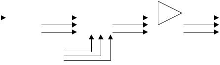
Theory of Operation
5.0 Video Electronics
|
|
|
|
|
|
|
|
|
|
|
U603, U604 |
|
|
U1 |
|
|
|
CS4988 |
|
|
|
NJM2284 |
|
|
|
|
|
|
Digital |
|
|
Analog |
|
|
|
|
|
|
|||
CS98000 |
|
|
Video |
|
|
Video |
|
|
Amp |
|
|
||
|
|
|
|
|
|
|
|
|
Video |
||||
|
|
|
|
Encoder |
|
|
|
Switch |
|
|
|
|
|
|
|
|
|
|
|
|
|
|
|
|
|||
|
|
|
|
U601 |
|
|
|
U602 |
|
|
NJM2267 |
|
Output |
|
|
|
|
|
|
|
|
|
|
|
|
|
|
External
Video
Video Block Diagram
Video signals may be generated internally (by U1) or passed-through from a set of external (VIDEO INPUT) connectors. Internally generated signals include DVD playback and On Screen Display (OSD) signals. OSD menus are accessed by pressing the SETTINGS button on the RF remote. When not playing back a DVD or generating an OSD, the media center defaults to passingthrough external video signals, much as a VCR does. The media center is capable of being connected to either NTSC or PAL televisions, where the desired format is selected via the OSD:
NTSC (National Television Standards Committee (USA) or National Television Systems Committee). A television standard with 60 fields per second, 30 frames per second, and 525 lines per frame. Variations of the standard include NTSC-M. A size used to digitize NTSC is 640x480 pixels. This standard is used in America and parts of Japan.
PAL (Phase Alternation Line). A television standard with 50 fields per second, 25 frames per second, and 625 lines per frame. Variations of the standard include PAL-B/G. A size used to digitize PAL is 768x576 pixels. This standard is used in parts of Africa, Australia, parts of Europe, and in the U.K.
The video interface drives several kinds of video digital to analog converters to generate the analog video monitor drive signals. U1 generates a standard ITU R.BT656 digital video data stream with embedded synchronization. This standard uses an 8 bit bus, with interleaved Y, Cr, Cb data. Synchronization information is embedded in the data stream, and exclusively uses values of 00 and FF (hex).Y values are from 1 to 254, with 1 being black. C values are from 1 to 254, with 128 being no chroma. The standard document should be consulted for further details on this bus.
The video encoder (essentially a video digital to analog converter), U601 on sheet 6 of the schematic, is a 44 pin quad flat pack, containing extensive video processing circuitry. The data sheet for this part (number CS4955) shows the block diagram and signal processing circuitry inside the chip. The chip has many programmable registers inside, to set different operation modes, etc. These registers are set by the main processor over a serial I2C bus (pins 32 and 33).
The CS4955 receives the ITU R.BT656 data bus, decodes the synchronization and separates the Y, Cr, and Cb values into separate data streams. The three channels of video data are processed appropriately, and sent to the digital to analog converters. Composite video is generated at pin 44, S-video Y and C are generated at pins 48 and 47, and RGB or YCrCb are generated at pins 39,40, and 43. The Composite video and S video are paralleled on the circuit board with the RGB (or YCrCb) signals. The appropriate DACs are enabled by internal control circuitry, commanded by the main processor, depending on the mode selected by the user. This allows either Composite and S- video, or Component video, to be placed on the output jacks of the AV28 console.
20
Theory of Operation
The 3 video signals are sent to the internal/external video MUX, U602, a NJM2285 chip. This chip will select either the internal or external set of video signals to be sent on further through the video chain. The selection is made by the control pins 2, 7, and 12, driven by transistor Q601, a level shifter driven by the main processor. No matter which mode the user selects, Composite and S- Video, or Component video, the same circuitry is used in the video chain.
After internal/external selection, the three video signals are sent to the output video drivers, U603 and U604. These are NJM2267 chips, with dual video channel capability. Each channel contains a clamp circuit on the input, which does a DC restore on the video signal by clamping the negative sync tip of the video signal to a DC voltage. The output driver drives the video signal through a 330uF capacitor (100-220uF on early units), and a 75-ohm resistor. This ensures equipment compatibility even if there are DC differences between the AV28 and the driven equipment. The 75ohm resistor provides reverse cable termination for best signal integrity. Video sent through a 330uF capacitor would have low frequency drop-off, causing sag in the video signal. This is corrected by the sag compensation pins of the NJM2267s, by sampling the video signal past the capacitors, and correcting of any sag that occurs. This prevents synchronization problems with video monitors that may otherwise occur.
For the Cr and Cb signal in component mode, and the C signal of the S-video signal, there is no synchronization pulse for the input clamp of the 2267s to clamp to, which could distort the negative tips of these chrominance signals. For these signals, the transistors Q601 and Q602 are turned on by the port pins of U601, supplying enough DC voltage to the signal to raise them above the clamp level, preventing any clamping action on them.
The CS4955 must receive a 27 MHz signal from the clock oscillator, with an accuracy of +- 1350hertz. This frequency is phase lock-looped inside the CS4955 to generate the 3.579545 MHz color subcarrier for the composite video signal, and must be of high accuracy so that television monitors can lock onto it and be able to decode color information to display.
6.0Tuner Electronics
6.1FM Tuner
The FM RF signal is provided by the F connector, J102, and goes to the FM front-end module. The antenna supplied with the media center is the standard Bose® FM dipole antenna. Contained within the FM front-end is a tuned RF amplifier, FM local oscillator and mixer.The 10.7 MHz IF output signal (pin 7 of the module) passes through a 10.7 MHz ceramic filter, CF101, to a FM IF amplifier, and then back through a second ceramic filter, CF102. Transistor Q301 and related circuitry form the FM IF amplifier that produces about 15 dB of voltage gain and provides the proper impedance matching for ceramic filters CF101 and CF102. These FM IF filter stages reject unwanted FM stations and noise.
The output signal from CF102 is fed to the LA1837 AM/FM detector IC, U101. This device contains the FM IF limiter, FM detector, FM stereo MPX decoder, S-meter circuitry which is used for seek processing, and most of the AM circuitry. The FM IF input signal to the LA1837 goes through several gain/limiter stages and then to a single-tuned, coil-based discriminator circuit. The discriminator coil, T103, is adjusted for minimum second harmonic audio distortion. The recovered FM composite signal appears on pin 23 of U101.
21

Theory of Operation
The composite audio signal is filtered by C124 and fed back into the LA1837 on pin 22. The value of C124 affects FM stereo separation performance. Stereo MPX decoding is also performed by U101 and the decoded left and right output signals are produced on pins 16 and 17.The pilot PLL VCO is completely internal to the LA1837 detector IC, not requiring an external 456 kHz ceramic resonator as in the older LA1836 and LA1851-based designs. The pilot PLL loop filter is formed by C120, R118, and C122 on pin 14.
Capacitors C132 and C133 and the internal resistance of the LA1837 set the FM de-emphasis. For a US unit the capacitor values are set to produce 75-uSec de-emphasis, and for Europe/Japan they are set to produce 50-uSec de-emphasis. MPX filters, T104 and T105, reject the residual 19 kHz pilot tone and 38 kHz sub-channel demodulation components.
The FM and AM S-meter signals, which are at pin 11 and 12 of the LA1837 respectively, are analog voltage levels that are proportional to the FM IF/AM RF input signal levels. These signals are used to control the FM stop level, FM force-mono level, and AM stop level. The nominal FM stop/force-mono levels are:
Parameter |
Frequency |
Level |
FM Seek Stop |
98.1 MHz |
30 dBf |
FM Force Mono |
98.1 MHz |
40 dBf |
Both S-meter signals are connected to a 2-input 6-bit analog to digital converter that resides in the LC72144 PLL IC, U103. During factory final test booth tuner alignment the appropriate test signal levels are injected into the UUT and the resultant ADC values for stop and force-mono levels are stored in the Flash memory of the main board. Level scaling is applied to both the AM and FM S- meter signals so that these signals do not saturate the dynamic range of the 3.3 V full scale A/D converter.
6.2 AM Tuner
The signal from the external AM loop antenna enters through the 2.5 mm AM jack, J300, and is fed to the AM front end module, T101. This module contains the varactor-tuned RF and Local Oscillator (LO) tracking circuit. This part is pre-tuned by the manufacturer for proper alignment in this circuit with AM antenna, and is further adjusted during factory alignment, if necessary. The RF tuned output appears on pin 12 and is fed to the AM buffer FET transistor Q103. This buffered output is sent to pin 27 of U101 which contains the AM RF amplifier, mixer, IF amplifier, AM detector, and AM S-meter circuitry. The 450 kHz AM IF output signal that appears on pin 2 is filtered by the IF filter, T102, and fed back into the IC on pin 4. The AM IF signal is demodulated by the LA1837 and the audio output is sent to pins 16 and 17, which are the left and right outputs.
The AM seek stop processing and factory alignment is performed in a similar fashion to FM mode processing. The S-meter voltage that corresponds to the desired AM stop level is stored during factory final booth tuner alignment in the main board Flash memory.
The nominal AM stop level is 56 dBuV/m at 1080 kHz.
22
 Loading...