


PRR726F71E
1
bitte aufbewahren
veuillez conserver
si prega di conservarle
please keep
por favor, guardar
por favor, guardar
lütfen saklayýnýz
Assembly instructions
Einbauanleitung
Notice de montage
Istruzioni di Montaggio
Instrucciones de montaje
пожалуйста, сохраните данное руководство
Montaj talimatlarý
Руководство по монтажу
s.v.p. bewaren
Installatievoorschrift
~
.
-
.
29
19
~26
~50
520 ÷ 546
520 ÷ 546
en
de
fr
it
es
pt
nl
tr
ru
Instruções de montagem

4
3
2
4a

5
6
7
7a
7c
7b
8

9
10
13
10
11
11 a
12
Y

en
Read the appliance's instructions before
installing and using.
The graphics in these Assembly
instructions are given as a guide only.
The manufacturer is exempt from all
liability if this manual's requirements
are not complied with.
Safety instructions
All operations relating to installation,
regulation and conversion to other
types of gas must be carried out by
an authorised installation engineer,
respecting applicable regulations,
standards and the specifications of
the gas and electricity providers.
Before you begin, turn off the
appliance's electricity and gas
supply.
You are recommended to contact the
Technical Assistance Service to
convert to another type of gas.
This appliance has been designed for
home use only, not for commercial or
professional use. This appliance cannot
be installed on yachts or in caravans.
The warranty will only be valid if the
appliance is used for the purpose for
which it was designed.
Before installing, you need to check that
local distribution conditions (gas type
and pressure) and the appliance's
adjustment are compatible (see table I).
The appliance's adjustment conditions
are written on the label or the
specifications plate.
This appliance can only be installed in a
well-ventilated place in accordance with
existing regulations and ventilation
specifications. The appliance must not
be connected to a combustion product
evacuation device.
The supply cable must be attached to
the unit to prevent it from touching hot
parts of the oven or hob.
Appliances with electrical supply must
be earthed.
Do not tamper with the appliance's
interior. If necessary, call our Technical
Assistance Service.
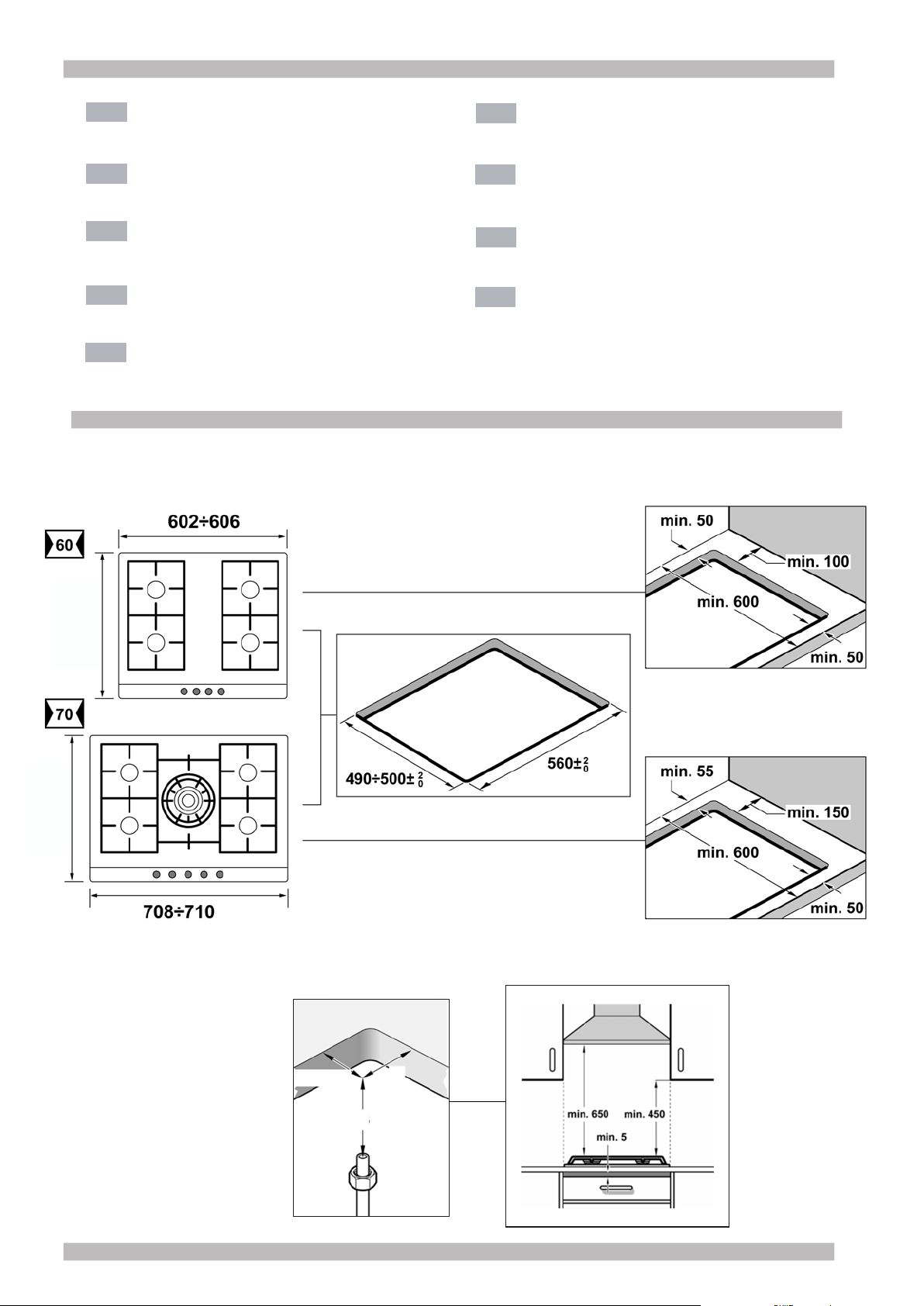
Before installing
This appliance is class 3 type, according
to the EN 30-1-1 regulation for gas
appliances: built-in appliance.
The units next to the appliance must be
made of non-inflammable materials. The
laminated covering and glue for
adhering it must be heat resistant.
This appliance cannot be installed
above fridges, washing machines,
dishwashers or similar.
An oven must have power cooling fan to
install a hob above it.
Check the oven's dimensions in its
installation manual.
If an extractor fan is installed, you must
follow the installation manual's
instructions, always keeping a minimum
distance of 650 mm to the hob.
Preparation of unit (fig. 1-2)
Make a cut of an appropriate size in the
work surface.
If the hob is electric or mixed (gas and
electricity) and there is no oven below,
place a non-inflammable separator
(e.g.metal or plywood) 10 mm from the
bottom of the hob. This will prevent
access to the base of the hob. If the hob
is gas, it is recommendable to place the
separator at the same distance.
On wooden work surfaces, varnish the
cutting surfaces with a special glue to
protect them from moisture.
Installation of appliance
The clips and the adhesive seal
(underside of the hob) are factory-fitted,
do not under any circumstances remove
them. The seal ensures that the entire
work surface will be watertight, and
prevents water seepage. In order to fit
the appliance into the kitchen unit, first
place the hob in the correct position then
loosen each of the clips so that
they all turn freely (it is not necessary to
completely undo them). Fit and centre
the hob.
Press the sides of the hob until it is
supported around its entire perimeter.
Turn the clips and tighten them fully. The
screws for the clips must be vertical to
the base of the housing. Fig. 3.
Removing the hob
Turn off the electricity and gas supply to
the appliance.
Unscrew the clips and proceed in the
reverse order to installation.
Gas connection (fig. 4)
The end of the inlet connection point of
the gas hob has a 1/2” (20.955 mm)
thread that allows for:
- rigid connection.
- connection using a flexible metal hose
(L min. 1 m - max. 3 m). With this option,
you must prevent the hose from coming
into contact with the moving parts of the
kitchen unit (for example, a drawer) or
accessing any spaces which might
become obstructed.
If you need to make a cylindrical
connection, replace the factory-fitted L-
tube with the one in the accessory bag.
Fig. 4a.
Please remember to insert the seal.
Warning! If any connection is handled,
check for tightness. Danger of leaks.
The manufacturer shall not be held liable
if any connection should leak, after
being handled.
Electric connection (fig. 5)
Check the voltage and power of the
appliance are compatible with the
electrical installation.
The hobs are supplied with a power
cable with or without a wall socket plug.
Provide an omnipolar cut-off switch with
a minimum contact gap of 3 mm (except
for plug connections, if the user has
access to it).
Appliances with plugs must only be
connected to sockets that have earth
wires correctly installed.
This appliance is type “Y”: the input
cable can only be changed by the
Technical Assistance Service and not
the user. The cable type and minimum
cross-section must be respected.
Changing the gas type
If the country’s regulations permit, this
appliance can be adapted to other types
of gas (see specifications plate). The
components necessary for this are in the
transformation kit supplied (according to
model). The kit is also available from our
Technical Assistance Service. The
following steps should be taken:
A) Changing the nozzles of the rapid,
semi-rapid and auxiliary burners of
the hob (fig. 6):
- Remove the pan supports, burner
covers and diffusers.
- Change the nozzles using the spanner
provided by our Technical Assistance
Service (code 424699), taking special
care to ensure that the nozzle does not
fall when it is removed from or fitted to
the burner.
Ensure that they are completely
tightened to guarantee the seal. Primary
air adjustment is not necessary with
these burners.
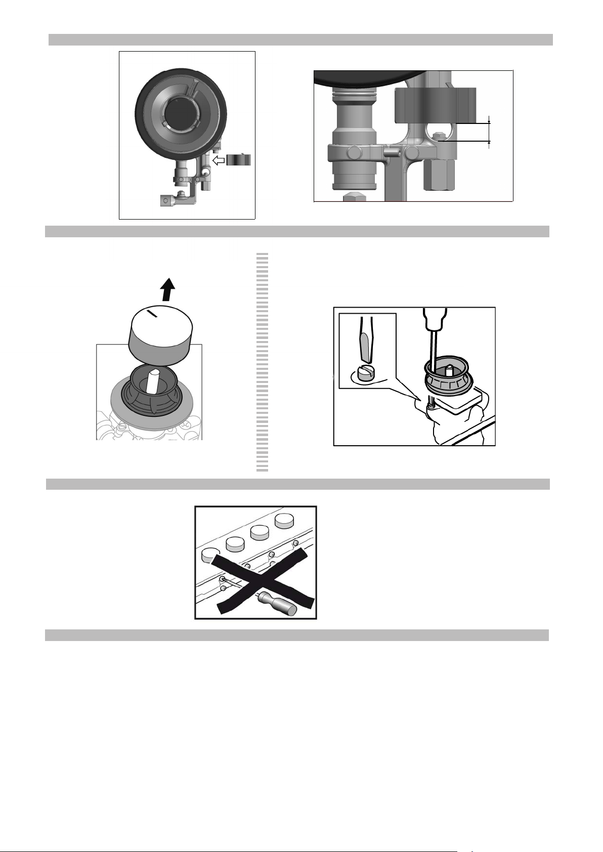
B) Changing the nozzles for double-
flame burners (fig. 7):
The glass panel and frame are fixed to
the rest of the hob using a clip mounting
system. The following steps must be
taken to remove the glass panel and
frame:
- Remove all the burner covers and pan
supports. Fig. 7a.
- Loosen the screws on the burners, fig.
7b-7c, and remove the control knobs
from their respective housings.
Use the disassembly lever 483196
available from our Technical Assistance
Service. To release the front clips, apply
the lever in the area shown in figures 8
according to the hob model.
Never use the lever on glass edges
which have no profile or frame!
- To release the rear clips, carefully raise
the entire glass panel and frame, as in
fig. 8a.
Changing the outer flame nozzle
(fig. 9a):
- Loosen the clamp screw to release the
bushing by moving it backwards to
access the main nozzle easily. Fig. a1.
- Remove the outer flame nozzle by
turning it towards the left. Fig. a2-a3.
- Screw in the new outer flame nozzle.
Fig. a3-a4, as in table II.
- Adjust the distance of the airflow
adjusting bushing L2 according to the
value -Z- shown in table II. Fig. a5.
- Tighten the clamp screw. Fig. a6.
Changing the inner flame nozzle
(fig. 9b):
- Unscrew the part M3 from the threaded
part M2; to do this, hold the threaded
part in the opposite direction.
- Remove the pipe from the M2 part. Fig.
b2.
- Disassemble parts M2 and M4 from
part M1. Fig. b3-b4.
- Remove the inner flame nozzle M4
from part M2. Fig. b5-b6.
- Screw in the new inner flame nozzle
M4, according to table II. Fig. b6-b7.
Refit all the components, proceeding in
the reverse order to removal.
- If the gas requires it, adjust the
distance with the airflow adjusting clip
 Loading...