


PSB 700 RE
Robert Bosch GmbH
Power Tools Division
70745 Leinfelden-Echterdingen
www.bosch-pt.com
1 609 929 N03 (2007.10) O / 118
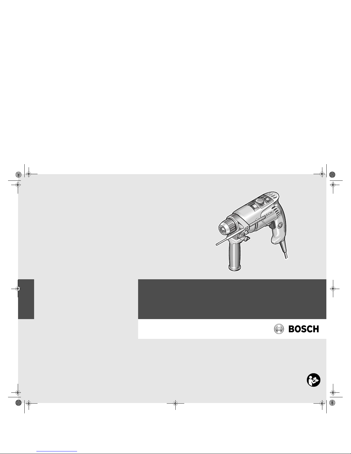
PSB
700 RE | 700 RES | 1000 RPE
de Originalbetriebsanleitung
en Original instructions
fr Notice originale
es Manual original
pt Manual original
it Istruzioni originali
nl Oorspronkelijke
gebruiksaanwijzing
da Original brugsanvisning
sv Bruksanvisning i original
no Original driftsinstruks
fi Alkuperäiset ohjeet
el Πρωτότυπο οδηγιών χρήσης
tr Orijinal işletme talimat
OBJ_DOKU-9105-001.fm Page 1 Wednesday, October 10, 2007 10:48 AM

1 609 929 N03 | (10.10.07) Bosch Power Tools
2 |
Deutsch. . . . . . . . . . . . . . . . . . . . . . . . . . . . Seite 5
English. . . . . . . . . . . . . . . . . . . . . . . . . . . . . . Page 14
Français. . . . . . . . . . . . . . . . . . . . . . . . . . . . . Page 23
Español . . . . . . . . . . . . . . . . . . . . . . . . . . . Página 32
Português . . . . . . . . . . . . . . . . . . . . . . . . . Página 41
Italiano . . . . . . . . . . . . . . . . . . . . . . . . . . . Pagina 50
Nederlands . . . . . . . . . . . . . . . . . . . . . . . . Pagina 59
Dansk . . . . . . . . . . . . . . . . . . . . . . . . . . . . . . Side 68
Svenska. . . . . . . . . . . . . . . . . . . . . . . . . . . . . Sida 76
Norsk. . . . . . . . . . . . . . . . . . . . . . . . . . . . . . . Side 84
Suomi . . . . . . . . . . . . . . . . . . . . . . . . . . . . . . Sivu 92
Ελληνικά . . . . . . . . . . . . . . . . . . . . . . . . . . . Σελίδα 100
Türkçe . . . . . . . . . . . . . . . . . . . . . . . . . . . . . Sayfa 109
OBJ_BUCH-530-001.book Page 2 Wednesday, October 10, 2007 10:49 AM

| 3
Bosch Power Tools 1 609 929 N03 | (10.10.07)
PSB 1000 RPE
x
BA
1
13
12
5
8
1
2
3
4
11 10
9
7 6
OBJ_BUCH-530-001.book Page 3 Wednesday, October 10, 2007 10:49 AM

1 609 929 N03 | (10.10.07) Bosch Power Tools
4 |
G
FE
DC
14
14
15
PSB 700 RE
PSB 700 RES
OBJ_BUCH-530-001.book Page 4 Wednesday, October 10, 2007 10:49 AM
Deutsch | 5
Bosch Power Tools 1 609 929 N03 | (10.10.07)
de
Allgemeine Sicherheitshinweise für Elektrowerkzeuge
Lesen Sie alle Sicherheitshinweise und Anweisungen. Ver-
säumnisse bei der Einhaltung der Sicherheitshinweise und Anweisungen können elektrischen
Schlag, Brand und/oder schwere Verletzungen
verursachen.
Bewahren Sie alle Sicherheitshinweise und Anweisungen für die Zukunft auf.
Der in den Sicherheitshinweisen verwendete Begriff „Elektrowerkzeug“ bezieht sich auf netzbetriebene Elektrowerkzeuge (mit Netzkabel) und
auf akkubetriebene Elektrowerkzeuge (ohne
Netzkabel).
1) Arbeitsplatzsicherheit
a) Halten Sie Ihren Arbeitsbereich sauber
und gut beleuchtet. Unordnung oder un-
beleuchtete Arbeitsbereiche können zu
Unfällen führen.
b) Arbeiten Sie mit dem Elektrowerkzeug
nicht in explosionsgefährdeter Umgebung, in der sich brennbare Flüssigkeiten, Gase oder Stäube befinden. Elektro-
werkzeuge erzeugen Funken, die den
Staub oder die Dämpfe entzünden können.
c) Halten Sie Kinder und andere Personen
während der Benutzung des Elektrowerkzeugs fern. Bei Ablenkung können Sie die
Kontrolle über das Gerät verlieren.
2) Elektrische Sicherheit
a) Der Anschlussstecker des Elektrowerk-
zeuges muss in die Steckdose passen.
Der Stecker darf in keiner Weise verändert werden. Verwenden Sie keine Adapterstecker gemeinsam mit schutzgeerdeten Elektrowerkzeugen. Unveränderte
Stecker und passende Steckdosen verringern das Risiko eines elektrischen Schlages.
b) Vermeiden Sie Körperkontakt mit geerde-
ten Oberflächen wie von Rohren, Heizungen, Herden und Kühlschränken. Es be-
steht ein erhöhtes Risiko durch
elektrischen Schlag, wenn Ihr Körper geerdet ist.
c) Halten Sie Elektrowerkzeuge von Regen
oder Nässe fern. Das Eindringen von Was-
ser in ein Elektrowerkzeug erhöht das Risiko eines elektrischen Schlages.
d) Zweckentfremden Sie das Kabel nicht,
um das Elektrowerkzeug zu tragen, aufzuhängen oder um den Stecker aus der
Steckdose zu ziehen. Halten Sie das Kabel fern von Hitze, Öl, scharfen Kanten
oder sich bewegenden Geräteteilen. Be-
schädigte oder verwickelte Kabel erhöhen
das Risiko eines elektrischen Schlages.
e) Wenn Sie mit einem Elektrowerkzeug im
Freien arbeiten, verwenden Sie nur Verlängerungskabel, die auch für den Außenbereich geeignet sind. Die Anwendung ei-
nes für den Außenbereich geeigneten
Verlängerungskabels verringert das Risiko
eines elektrischen Schlages.
f) Wenn der Betrieb des Elektrowerkzeuges
in feuchter Umgebung nicht vermeidbar
ist, verwenden Sie einen Fehlerstromschutzschalter. Der Einsatz eines Fehler-
stromschutzschalters vermindert das Risiko eines elektrischen Schlages.
3) Sicherheit von Personen
a) Seien Sie aufmerksam, achten Sie darauf,
was Sie tun, und gehen Sie mit Vernunft
an die Arbeit mit einem Elektrowerkzeug.
Benutzen Sie kein Elektrowerkzeug,
wenn Sie müde sind oder unter dem Einfluss von Drogen, Alkohol oder Medikamenten stehen. Ein Moment der Unacht-
samkeit beim Gebrauch des
Elektrowerkzeuges kann zu ernsthaften
Verletzungen führen.
WARNUNG
OBJ_BUCH-530-001.book Page 5 Wednesday, October 10, 2007 10:49 AM
1 609 929 N03 | (10.10.07) Bosch Power Tools
6 | Deutsch
b) Tragen Sie persönliche Schutzausrüstung
und immer eine Schutzbrille. Das Tragen
persönlicher Schutzausrüstung, wie Staubmaske, rutschfeste Sicherheitsschuhe,
Schutzhelm oder Gehörschutz, je nach Art
und Einsatz des Elektrowerkzeuges, verringert das Risiko von Verletzungen.
c) Vermeiden Sie eine unbeabsichtigte Inbe-
triebnahme. Vergewissern Sie sich, dass
das Elektrowerkzeug ausgeschaltet ist,
bevor Sie es an die Stromversorgung
und/oder den Akku anschließen, es aufnehmen oder tragen. Wenn Sie beim Tra-
gen des Elektrowerkzeuges den Finger am
Schalter haben oder das Gerät eingeschaltet an die Stromversorgung anschließen,
kann dies zu Unfällen führen.
d) Entfernen Sie Einstellwerkzeuge oder
Schraubenschlüssel, bevor Sie das Elektrowerkzeug einschalten. Ein Werkzeug
oder Schlüssel, der sich in einem drehenden Geräteteil befindet, kann zu Verletzungen führen.
e) Vermeiden Sie eine abnormale Körperhal-
tung. Sorgen Sie für einen sicheren Stand
und halten Sie jederzeit das Gleichgewicht. Dadurch können Sie das Elektro-
werkzeug in unerwarteten Situationen besser kontrollieren.
f) Tragen Sie geeignete Kleidung. Tragen
Sie keine weite Kleidung oder Schmuck.
Halten Sie Haare, Kleidung und Handschuhe fern von sich bewegenden Teilen.
Lockere Kleidung, Schmuck oder lange
Haare können von sich bewegenden Teilen
erfasst werden.
g) Wenn Staubabsaug- und -auffangein-
richtungen montiert werden können,
vergewissern Sie sich, dass diese angeschlossen sind und richtig verwendet
werden. Verwendung einer Staubabsau-
gung kann Gefährdungen durch Staub verringern.
4) Verwendung und Behandlung des Elektrowerkzeuges
a) Überlasten Sie das Gerät nicht. Verwen-
den Sie für Ihre Arbeit das dafür bestimmte Elektrowerkzeug. Mit dem pas-
senden Elektrowerkzeug arbeiten Sie
besser und sicherer im angegebenen Leistungsbereich.
b) Benutzen Sie kein Elektrowerkzeug, des-
sen Schalter defekt ist. Ein Elektrowerk-
zeug, das sich nicht mehr ein- oder ausschalten lässt, ist gefährlich und muss
repariert werden.
c) Ziehen Sie den Stecker aus der Steckdo-
se und/oder entfernen Sie den Akku, bevor Sie Geräteeinstellungen vornehmen,
Zubehörteile wechseln oder das Gerät
weglegen. Diese Vorsichtsmaßnahme ver-
hindert den unbeabsichtigten Start des
Elektrowerkzeuges.
d) Bewahren Sie unbenutzte Elektrowerk-
zeuge außerhalb der Reichweite von Kindern auf. Lassen Sie Personen das Gerät
nicht benutzen, die mit diesem nicht vertraut sind oder diese Anweisungen nicht
gelesen haben. Elektrowerkzeuge sind ge-
fährlich, wenn sie von unerfahrenen Personen benutzt werden.
e) Pflegen Sie Elektrowerkzeuge mit Sorg-
falt. Kontrollieren Sie, ob bewegliche Teile einwandfrei funktionieren und nicht
klemmen, ob Teile gebrochen oder so beschädigt sind, dass die Funktion des Elektrowerkzeuges beeinträchtigt ist. Lassen
Sie beschädigte Teile vor dem Einsatz des
Gerätes reparieren. Viele Unfälle haben ih-
re Ursache in schlecht gewarteten Elektrowerkzeugen.
f) Halten Sie Schneidwerkzeuge scharf und
sauber. Sorgfältig gepflegte Schneidwerk-
zeuge mit scharfen Schneidkanten verklemmen sich weniger und sind leichter zu
führen.
OBJ_BUCH-530-001.book Page 6 Wednesday, October 10, 2007 10:49 AM
Deutsch | 7
Bosch Power Tools 1 609 929 N03 | (10.10.07)
g) Verwenden Sie Elektrowerkzeug, Zube-
hör, Einsatzwerkzeuge usw. entsprechend diesen Anweisungen. Berücksichtigen Sie dabei die Arbeitsbedingungen
und die auszuführende Tätigkeit. Der Ge-
brauch von Elektrowerkzeugen für andere
als die vorgesehenen Anwendungen kann
zu gefährlichen Situationen führen.
5) Service
a) Lassen Sie Ihr Elektrowerkzeug nur von
qualifiziertem Fachpersonal und nur mit
Original-Ersatzteilen reparieren. Damit
wird sichergestellt, dass die Sicherheit des
Elektrowerkzeuges erhalten bleibt.
Gerätespezifische
Sicherheitshinweise
f Tragen Sie Gehörschutz bei der Benutzung
von Schlagbohrmaschinen. Die Einwirkung
von Lärm kann Gehörverlust bewirken.
f Benutzen Sie die mit dem Elektrowerkzeug
mitgelieferten Zusatzgriffe. Der Verlust der
Kontrolle über das Elektrowerkzeug kann zu
Verletzungen führen.
f Verwenden Sie geeignete Suchgeräte, um
verborgene Versorgungsleitungen aufzuspüren, oder ziehen Sie die örtliche Versorgungsgesellschaft hinzu. Kontakt mit Elektro-
leitungen kann zu Feuer und elektrischem
Schlag führen. Beschädigung einer Gasleitung
kann zur Explosion führen. Eindringen in eine
Wasserleitung verursacht Sachbeschädigung.
f Schalten Sie das Elektrowerkzeug sofort
aus, wenn das Einsatzwerkzeug blockiert.
Seien Sie auf hohe Reaktionsmomente gefasst, die einen Rückschlag verursachen. Das
Einsatzwerkzeug blockiert wenn:
— das Elektrowerkzeug überlastet wird oder
— es im zu bearbeitenden Werkstück verkantet.
f Fassen Sie das Elektrowerkzeug nur an den
isolierten Griffflächen an, wenn Sie Arbeiten
ausführen, bei denen das Einsatzwerkzeug
verborgene Stromleitungen oder das eigene
Netzkabel treffen kann. Kontakt mit einer
spannungsführenden Leitung setzt auch Metallteile des Elektrowerkzeuges unter Spannung und führt zu einem elektrischen Schlag.
f Halten Sie das Elektrowerkzeug beim Arbei-
ten fest mit beiden Händen und sorgen Sie
für einen sicheren Stand. Das Elektrowerk-
zeug wird mit zwei Händen sicherer geführt.
f Sichern Sie das Werkstück. Ein mit Spann-
vorrichtungen oder Schraubstock festgehaltenes Werkstück ist sicherer gehalten als mit Ihrer Hand.
f Halten Sie Ihren Arbeitsplatz sauber. Materi-
almischungen sind besonders gefährlich.
Leichtmetallstaub kann brennen oder explodieren.
f Warten Sie, bis das Elektrowerkzeug zum
Stillstand gekommen ist, bevor Sie es ablegen. Das Einsatzwerkzeug kann sich verhaken
und zum Verlust der Kontrolle über das Elektrowerkzeug führen.
f Benutzen Sie das Elektrowerkzeug nicht mit
beschädigtem Kabel. Berühren Sie das beschädigte Kabel nicht und ziehen Sie den
Netzstecker, wenn das Kabel während des
Arbeitens beschädigt wird. Beschädigte Ka-
bel erhöhen das Risiko eines elektrischen
Schlages.
Funktionsbeschreibung
Lesen Sie alle Sicherheitshinweise
und Anweisungen. Versäumnisse
bei der Einhaltung der Sicherheitshinweise und Anweisungen können
elektrischen Schlag, Brand und/oder
schwere Verletzungen verursachen.
OBJ_BUCH-530-001.book Page 7 Wednesday, October 10, 2007 10:49 AM
1 609 929 N03 | (10.10.07) Bosch Power Tools
8 | Deutsch
Bestimmungsgemäßer Gebrauch
Das Elektrowerkzeug ist bestimmt zum Schlagbohren in Ziegel, Beton und Gestein, sowie zum
Bohren in Holz, Metall, Keramik und Kunststoff.
Geräte mit elektronischer Regelung und
Rechts-/ Linkslauf sind auch geeignet zum
Schrauben und Gewindeschneiden.
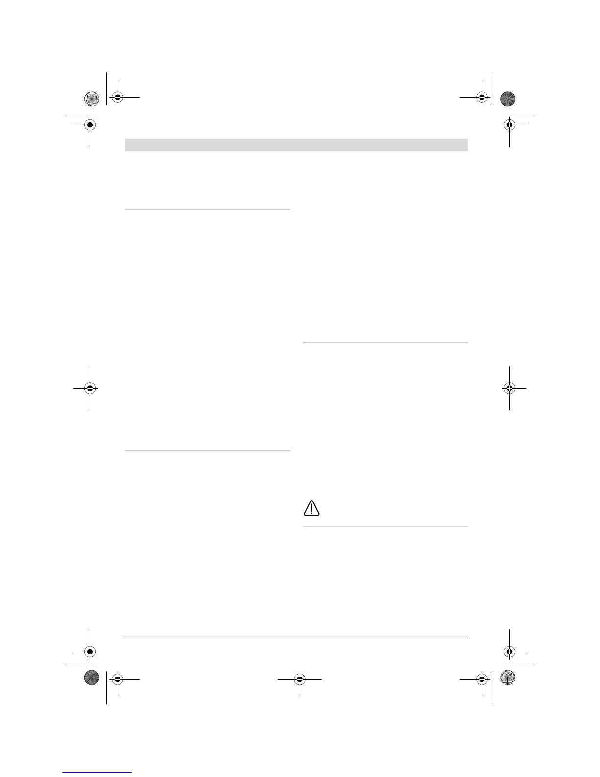
Abgebildete Komponenten
Die Nummerierung der abgebildeten Komponenten bezieht sich auf die Darstellung des Elektrowerkzeuges auf der Grafikseite.
1 Schnellspannbohrfutter*
2 Umschalter „Bohren/Schlagbohren“
3 Stellrad „PowerControl“ (PSB 1000 RPE)
4 Umschalter „Bohren/Schrauben“
5 Feststelltaste für Ein-/Ausschalter
6 Ein-/Ausschalter
7 Drehrichtungsumschalter
8 Taste für Tiefenanschlageinstellung
9 Flügelschraube für Zusatzgriffverstellung
10 Zusatzgriff*
11 Tiefenanschlag*
12 Bohrfutterschlüssel*
13 Zahnkranzbohrfutter*
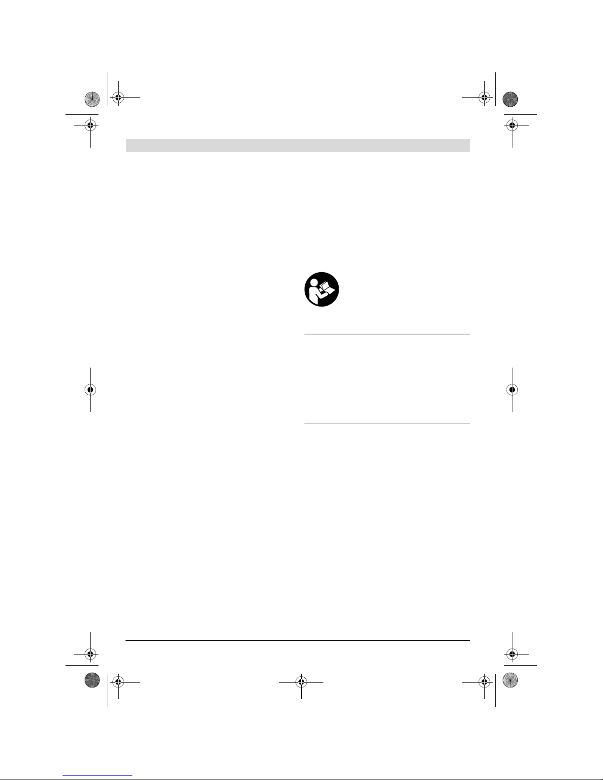
14 Innensechskantschlüssel **
15 Stellrad Drehzahlvorwahl(PSB 700 RE/
PSB 700 RES)
*Abgebildetes oder beschriebenes Zubehör gehört
nicht zum Standard-Lieferumfang.
**handelsüblich (nicht im Lieferumfang enthalten)
Technische Daten
Schlagbohrmaschine PSB 700 RE PSB 700 RES PSB 1000 RPE
Sachnummer
0 603 386 7.. 0 603 386 7.. 0 603 386 8..
Nennaufnahmeleistung
W 701 701 1010
Abgabeleistung
W 360 360 510
Leerlaufdrehzahl
min
-1
0 – 3000 0 – 3000 0 – 2700
Nenndrehzahl
min
-1
1950 1 950 2700
Schlagzahl
min
-1
48000 48000 43000
Nenndrehmoment
Nm 1,75 1,75 1,65
Vollautomatische Spindelarretierung (Auto-Lock)
z zz
Spindelhalsdurchmesser
mm 43 43 43
max. Bohr-
Ø
–Beton
–Stahl
–Holz
mm
mm
mm
16
12
30
16
12
30
16
12
30
Bohrfutterspannbereich
mm 1,5 – 13 1,5–13 1,5 – 13
Gewicht entsprechend EPTAProcedure 01/2003
kg 1,9 1,9 1,9
Schutzklasse
/II / II /II
Angaben gelten für Nennspannungen [U] 230/240 V. Bei niedrigeren Spannungen und in länderspezifischen Ausführungen können diese Angaben variieren.
Bitte beachten Sie die Sachnummer auf dem Typenschild Ihres Elektrowerkzeugs. Die Handelsbezeichnungen einzelner
Elektrowerkzeuge können variieren.
OBJ_BUCH-530-001.book Page 8 Wednesday, October 10, 2007 10:49 AM

Deutsch | 9
Bosch Power Tools 1 609 929 N03 | (10.10.07)
Geräusch-/Vibrationsinformation
Messwerte ermittelt entsprechend EN 60745.
Der A-bewertete Geräuschpegel des Gerätes beträgt typischerweise: Schalldruckpegel 98 dB(A);
Schallleistungspegel 109 dB(A). Unsicherheit K= 3 dB.
Gehörschutz tragen!
Der in diesen Anweisungen angegebene Schwingungspegel ist entsprechend einem in EN 60745
genormten Messverfahren gemessen worden
und kann für den Vergleich von Elektrowerkzeugen miteinander verwendet werden. Er eignet
sich auch für eine vorläufige Einschätzung der
Schwingungsbelastung.
Der angegebene Schwingungspegel repräsentiert die hauptsächlichen Anwendungen des Elektrowerkzeugs. Wenn allerdings das Elektrowerkzeug für andere Anwendungen, mit
abweichenden Einsatzwerkzeugen oder ungenügender Wartung eingesetzt wird, kann der
Schwingungspegel abweichen. Dies kann die
Schwingungsbelastung über den gesamten Arbeitszeitraum deutlich erhöhen.
Für eine genaue Abschätzung der Schwingungsbelastung sollten auch die Zeiten berücksichtigt
werden, in denen das Gerät abgeschaltet ist oder
zwar läuft, aber nicht tatsächlich im Einsatz ist.
Dies kann die Schwingungsbelastung über den
gesamten Arbeitszeitraum deutlich reduzieren.
Legen Sie zusätzliche Sicherheitsmaßnahmen
zum Schutz des Bedieners vor der Wirkung von
Schwingungen fest wie zum Beispiel: Wartung
von Elektrowerkzeug und Einsatzwerkzeugen,
Warmhalten der Hände, Organisation der Arbeitsabläufe.
Konformitätserklärung
Wir erklären in alleiniger Verantwortung, dass
das unter „Technische Daten“ beschriebene Produkt mit den folgenden Normen oder normativen
Dokumenten übereinstimmt: EN 60745 gemäß
den Bestimmungen der Richtlinien
2004/108/EG, 98/37/EG (bis 28.12.2009),
2006/42/EG (ab 29.12.2009).
Technische Unterlagen bei:
Robert Bosch GmbH, PT/ESC,
D-70745 Leinfelden-Echterdingen
30.08.2007, Robert Bosch GmbH, Power Tools Division
D-70745 Leinfelden-Echterdingen
Montage
f Ziehen Sie vor allen Arbeiten am Elektro-
werkzeug den Netzstecker aus der Steckdose.
0 603 386 7.. 0 603 386 8..
Schwingungsgesamtwerte (Vektorsumme dreier Richtungen) ermittelt entsprechend EN 60745:
Bohren in Metall:
Schwingungsemissionswert a
h
Unsicherheit K=
Schlagbohren in Beton:
Schwingungsemissionswert a
h
Unsicherheit K=
Schrauben:
Schwingungsemissionswert a
h
Unsicherheit K=
m/s
2
m/s
2
m/s
2
m/s
2
m/s
2
m/s
2
5
1,5
30
1,5
4
1,5
5,5
1,5
24
2,5
< 2,5
1,5
Dr. Egbert Schneider
Senior Vice President
Engineering
Dr. Eckerhard Strötgen
Head of Product
Certification
OBJ_BUCH-530-001.book Page 9 Wednesday, October 10, 2007 10:49 AM
1 609 929 N03 | (10.10.07) Bosch Power Tools
10 | Deutsch
Zusatzgriff
f Verwenden Sie Ihr Elektrowerkzeug nur mit
dem Zusatzgriff 10.
Sie können den Zusatzgriff 10 beliebig schwenken, um eine sichere und ermüdungsarme Arbeitshaltung zu erreichen.
Drehen Sie die Flügelschraube für die Zusatzgriffverstellung 9 entgegen dem Uhrzeigersinn und
schwenken Sie den Zusatzgriff 10 in die gewünschte Position. Danach drehen Sie die Flügelschraube 9 im Uhrzeigersinn wieder fest.
Bohrtiefe einstellen
Mit dem Tiefenanschlag 11 kann die gewünschte
Bohrtiefe X festgelegt werden.
Drücken Sie die Taste für die Tiefenanschlageinstellung 8 und setzen Sie den Tiefenanschlag in
den Zusatzgriff 10 ein.
Ziehen Sie den Tiefenanschlag so weit heraus,
dass der Abstand zwischen der Spitze des Bohrers und der Spitze des Tiefenanschlags der gewünschten Bohrtiefe X entspricht.
Die Riffelung am Tiefenanschlag 11 muss nach
oben zeigen.
Werkzeugwechsel
Schnellspannbohrfutter (siehe Bild A)
Bei nicht gedrücktem Ein-/Ausschalter 6 wird die
Bohrspindel arretiert. Dies ermöglicht ein schnelles, bequemes und einfaches Wechseln des Einsatzwerkzeuges im Bohrfutter.
Öffnen Sie das Schnellspannbohrfutter 1 durch
Drehen in Drehrichtung n, bis das Werkzeug eingesetzt werden kann. Setzen Sie das Werkzeug
ein.
Drehen Sie die Hülse des Schnellspannbohrfutters 1 in Drehrichtung o von Hand kräftig zu, bis
kein Überrasten mehr hörbar ist. Das Bohrfutter
wird dadurch automatisch verriegelt.
Die Verriegelung löst sich wieder, wenn Sie zum
Entfernen des Werkzeuges die Hülse in Gegenrichtung drehen.
Zahnkranzbohrfutter (siehe Bild B)
f Tragen Sie beim Werkzeugwechsel Schutz-
handschuhe. Das Bohrfutter kann sich bei län-
geren Arbeitsvorgängen stark erwärmen.
Öffnen Sie das Zahnkranzbohrfutter 13 durch
Drehen, bis das Werkzeug eingesetzt werden
kann. Setzen Sie das Werkzeug ein.
Stecken Sie den Bohrfutterschlüssel 12 in die
entsprechenden Bohrungen des Zahnkranzbohrfutters 13 und spannen Sie das Werkzeug gleichmäßig fest.
Schraubwerkzeuge
Bei der Verwendung von Schrauberbits sollten
Sie immer einen Universalbithalter benutzen.
Verwenden Sie nur zum Schraubenkopf passende Schrauberbits.
Zum Schrauben stellen Sie den Umschalter „Bohren/Schlagbohren“ 2 immer auf das Symbol
„Bohren“.
Bohrfutter wechseln
Bohrfutter demontieren (siehe Bild C)
Spannen Sie einen Innensechskantschlüssel 14
mit dem kurzen Schaft voran in das Schnellspannbohrfutter 1 ein.
Legen Sie das Elektrowerkzeug auf eine standfeste Unterlage, z. B. eine Werkbank. Halten Sie
das Elektrowerkzeug fest und lösen Sie das
Schnellspannbohrfutter 1 durch Drehen des Innensechskantschlüssels 14 in Drehrichtung n.
Ein festsitzendes Schnellspannbohrfutter wird
durch einen leichten Schlag auf den langen
Schaft des Innensechskantschlüssels 14 gelöst.
Entfernen Sie den Innensechskantschlüssel aus
dem Schnellspannbohrfutter und schrauben Sie
das Schnellspannbohrfutter vollständig ab.
Bohrfutter montieren (siehe Bild D)
Die Montage des Schnellspannbohrfutters erfolgt in umgekehrter Reihenfolge.
Das Bohrfutter muss mit einem Anzugsdrehmoment von ca. 20– 25 Nm festgezogen werden.
OBJ_BUCH-530-001.book Page 10 Wednesday, October 10, 2007 10:49 AM

Deutsch | 11
Bosch Power Tools 1 609 929 N03 | (10.10.07)
Staub-/Späneabsaugung
f Stäube von Materialien wie bleihaltigem An-
strich, einigen Holzarten, Mineralien und Metall können gesundheitsschädlich sein. Berühren oder Einatmen der Stäube können
allergische Reaktionen und/oder Atemwegserkrankungen des Benutzers oder in der
Nähe befindlicher Personen hervorrufen.
Bestimmte Stäube wie Eichen- oder Buchenstaub gelten als krebserzeugend, besonders
in Verbindung mit Zusatzstoffen zur Holzbehandlung (Chromat, Holzschutzmittel). Asbesthaltiges Material darf nur von Fachleuten
bearbeitet werden.
– Benutzen Sie möglichst eine Staubabsau-
gung.
– Sorgen Sie für gute Belüftung des Arbeits-
platzes.
– Es wird empfohlen, eine Atemschutzmaske
mit Filterklasse P2 zu tragen.
Beachten Sie in Ihrem Land gültige Vorschriften für die zu bearbeitenden Materialien.
Betrieb
Inbetriebnahme
f Beachten Sie die Netzspannung! Die Span-
nung der Stromquelle muss mit den Angaben
auf dem Typenschild des Elektrowerkzeuges
übereinstimmen. Mit 230 V gekennzeichnete
Elektrowerkzeuge können auch an 220 V betrieben werden.
Drehrichtung einstellen (siehe Bilder E–F)
Mit dem Drehrichtungsumschalter 7 können Sie
die Drehrichtung des Elektrowerkzeuges ändern.
Bei gedrücktem Ein-/Ausschalter 6 ist dies jedoch nicht möglich.
Rechtslauf: Zum Bohren und Eindrehen von
Schrauben drücken Sie den Drehrichtungsumschalter 7 nach links bis zum Anschlag durch.
Linkslauf: Zum Lösen bzw. Herausdrehen von
Schrauben und Muttern drücken Sie den Drehrichtungsumschalter 7 nach rechts bis zum Anschlag durch.
Betriebsart einstellen
Bohren und Schrauben
Stellen Sie den Umschalter 2 auf das
Symbol „Bohren“.
Schlagbohren
Stellen Sie den Umschalter 2 auf das
Symbol „Schlagbohren“.
Der Umschalter 2 rastet spürbar ein und kann
auch bei laufendem Motor betätigt werden.
Ein-/Ausschalten
Drücken Sie zur Inbetriebnahme des Elektrowerkzeuges den Ein-/Ausschalter 6 und halten
Sie ihn gedrückt.
Zum Feststellen des gedrückten Ein-/Ausschalters 6 drücken Sie die Feststelltaste 5.
Um das Elektrowerkzeug auszuschalten lassen
Sie den Ein-/Ausschalter 6 los bzw. wenn er mit
der Feststelltaste 5 arretiert ist, drücken Sie den
Ein-/Ausschalter 6 kurz und lassen ihn dann los.
Drehzahl/Schlagzahl einstellen
Sie können die Drehzahl/Schlagzahl des eingeschalteten Elektrowerkzeugs stufenlos regulieren, je nachdem, wie weit Sie den Ein-/Ausschalter 6 eindrücken.
Leichter Druck auf den Ein-/Ausschalter 6 bewirkt eine niedrige Drehzahl/Schlagzahl. Mit zunehmendem Druck erhöht sich die Drehzahl/Schlagzahl.
Drehzahl/Schlagzahl vorwählen (siehe Bild G)
(PSB 700 RE/PSB 700 RES)
Mit dem Stellrad Drehzahlvorwahl 15 können Sie
die benötigte Drehzahl/Schlagzahl auch während
des Betriebes vorwählen.
Die erforderliche Drehzahl/Schlagzahl ist vom
Werkstoff und den Arbeitsbedingungen abhängig
und kann durch praktischen Versuch ermittelt
werden.
OBJ_BUCH-530-001.book Page 11 Wednesday, October 10, 2007 10:49 AM

1 609 929 N03 | (10.10.07) Bosch Power Tools
12 | Deutsch
Elektronische Drehmomentbegrenzung/Drehzahlvorwahl (Torque Control) (PSB 1000 RPE)
Zum Bohren mit Drehzahlvorwahl
stellen Sie den Umschalter 4 auf das
Symbol „Bohren“. Mit dem Stellrad 3
können Sie die benötigte Drehzahl
auch während des Betriebes vorwählen.
Zum Schrauben mit Drehmomentbe-
grenzung stellen Sie den Umschalter
4 auf das Symbol „Schrauben“. Mit
dem Stellrad 3 können Sie das an der
Bohrspindel wirkende Drehmoment
stufenlos auch während des Betrie-
bes vorwählen:
I= niedriges Drehmoment, III=hohes Drehmoment.
Die maximale Drehzahl wird automatisch dem
eingestellten Drehmoment angepasst.
Wird beim Schraubvorgang das vorgewählte
Drehmoment erreicht, schaltet das Elektrowerkzeug ab; das Einsatzwerkzeug dreht sich nicht
mehr. Wird das Elektrowerkzeug danach entlastet und der Ein-/Ausschalter 6 ist noch gedrückt,
dreht sich das Einsatzwerkzeug aus Sicherheitsgründen nur mit sehr geringer Drehzahl weiter.
Nach kurzzeitigem Loslassen des Ein-/Ausschalters 6 kann die nächste Schraube mit dem gleichen Drehmoment angezogen werden.
Zum Schrauben ohne Drehmoment-
begrenzung drehen Sie das Stellrad
3 auf Rechtsanschlag. Diese Einstel-
lung ist erforderlich, wenn das Dreh-
moment in Position III nicht aus-
reicht.
Arbeitshinweise
f Setzen Sie das Elektrowerkzeug nur ausge-
schaltet auf die Mutter/Schraube auf. Sich
drehende Einsatzwerkzeuge können abrutschen.
Tipps
Nach längerem Arbeiten mit kleiner Drehzahl sollten Sie das Elektrowerkzeug zur Abkühlung ca. 3
Minuten lang bei maximaler Drehzahl im Leerlauf
drehen lassen.
Um Fliesen zu bohren, stellen Sie den Umschalter 2 auf das Symbol „Bohren“. Nach dem Durchbohren der Fliese stellen Sie den Umschalter auf
das Symbol „Schlagbohren“ um und arbeiten mit
Schlag.
Bei Arbeiten in Beton, Gestein und Mauerwerk
verwenden Sie Hartmetallbohrer.
Verwenden Sie beim Bohren in Metall nur einwandfreie, geschärfte HSS-Bohrer
(HSS= Hochleistungs-Schnellschnittstahl). Entsprechende Qualität garantiert das Bosch-Zubehör-Programm.
Mit dem Bohrerschärfgerät (Zubehör) können
Sie Spiralbohrer mit einem Durchmesser von
2,5– 10 mm mühelos schärfen.
Wartung und Service
Wartung und Reinigung
f Ziehen Sie vor allen Arbeiten am Elektro-
werkzeug den Netzstecker aus der Steckdose.
f Halten Sie das Elektrowerkzeug und die Lüf-
tungsschlitze sauber, um gut und sicher zu
arbeiten.
Sollte das Elektrowerkzeug trotz sorgfältiger Herstellungs- und Prüfverfahren einmal ausfallen, ist
die Reparatur von einer autorisierten Kundendienststelle für Bosch-Elektrowerkzeuge ausführen zu lassen.
Geben Sie bei allen Rückfragen und Ersatzteilbestellungen bitte unbedingt die 10-stellige Sachnummer laut Typenschild des Elektrowerkzeuges
an.
OBJ_BUCH-530-001.book Page 12 Wednesday, October 10, 2007 10:49 AM
Deutsch | 13
Bosch Power Tools 1 609 929 N03 | (10.10.07)
Kundendienst und Kundenberatung
Der Kundendienst beantwortet Ihre Fragen zu
Reparatur und Wartung Ihres Produkts sowie zu
Ersatzteilen. Explosionszeichnungen und Informationen zu Ersatzteilen finden Sie auch unter:
www.bosch-pt.com
Das Bosch-Kundenberater-Team hilft Ihnen gerne
bei Fragen zu Kauf, Anwendung und Einstellung
von Produkten und Zubehören.
www.powertool-portal.de, das Internetportal
für Heimwerker und Gartenfreunde.
www.dha.de, das komplette Service-Angebot
der Deutschen Heimwerker Akademie.
Deutschland
Robert Bosch GmbH
Servicezentrum Elektrowerkzeuge
Zur Luhne 2
37589 Kalefeld – Willershausen
Tel. Kundendienst: +49 (1805) 70 74 10
Fax: +49 (1805) 70 74 11
E-Mail: Servicezentrum.Elektrowerkzeuge@de.
bosch.com
Tel. Kundenberatung: +49 (1803) 33 57 99
Fax: +49 (711) 7 58 19 30
E-Mail: kundenberatung.ew@de.bosch.com
Österreich
ABE Service GmbH
Jochen-Rindt-Straße 1
1232 Wien
Tel. Service: +43 (01) 61 03 80
Fax: +43 (01) 61 03 84 91
Tel. Kundenberater: +43 (01) 7 97 22 30 66
E-Mail: abe@abe-service.co.at
Schweiz
Tel.: +41 (044) 8 47 15 11
Fax: +41 (044) 8 47 15 51
Luxemburg
Tel.: +32 (070) 22 55 65
Fax: +32 (070) 22 55 75
E-Mail: outillage.gereedschap@be.bosch.com
Entsorgung
Elektrowerkzeuge, Zubehör und Verpackungen
sollen einer umweltgerechten Wiederverwertung
zugeführt werden.
Nur für EU-Länder:
Werfen Sie Elektrowerkzeuge nicht
in den Hausmüll!
Gemäß der Europäischen Richtlinie 2002/96/EG über Elektro- und
Elektronik-Altgeräte und ihrer Um-
setzung in nationales Recht müssen nicht mehr gebrauchsfähige Elektrowerkzeuge getrennt gesammelt und einer
umweltgerechten Wiederverwertung zugeführt
werden.
Änderungen vorbehalten.
OBJ_BUCH-530-001.book Page 13 Wednesday, October 10, 2007 10:49 AM

1 609 929 N03 | (10.10.07) Bosch Power Tools
14 | English
en
General Power Tool Safety
Warnings
Read all safety warnings and all
instructions. Failure to follow the
warnings and instructions may result in electric
shock, fire and/or serious injury.
Save all warnings and instructions for future
reference.
The term “power tool” in the warnings refers to
your mains-operated (corded) power tool or battery-operated (cordless) power tool.
1) Work area safety
a) Keep work area clean and well lit. Clut-
tered or dark areas invite accidents.
b) Do not operate power tools in explosive
atmospheres, such as in the presence of
flammable liquids, gases or dust. Power
tools create sparks which may ignite the
dust or fumes.
c) Keep children and bystanders away while
operating a power tool. Distractions can
cause you to lose control.
2) Electrical safety
a) Power tool plugs must match the outlet.
Never modify the plug in any way. Do not
use any adapter plugs with earthed
(grounded) power tools. Unmodified
plugs and matching outlets will reduce risk
of electric shock.
b) Avoid body contact with earthed or
grounded surfaces, such as pipes, radiators, ranges and refrigerators. There is an
increased risk of electric shock if your
body is earthed or grounded.
c) Do not expose power tools to rain or wet
conditions. Water entering a power tool
will increase the risk of electric shock.
d) Do not abuse the cord. Never use the cord
for carrying, pulling or unplugging the
power tool. Keep cord away from heat,
oil, sharp edges and moving parts. Dam-
aged or entangled cords increase the risk
of electric shock.
e) When operating a power tool outdoors,
use an extension cord suitable for outdoor use. Use of a cord suitable for out-
door use reduces the risk of electric shock.
f) If operating a power tool in a damp loca-
tion is unavoidable, use a residual current
device (RCD) protected supply. Use of an
RCD reduces the risk of electric shock.
3) Personal safety
a) Stay alert, watch what you are doing and
use common sense when operating a
power tool. Do not use a power tool while
you are tired or under the influence of
drugs, alcohol or medication. A moment
of inattention while operating power tools
may result in serious personal injury.
b) Use personal protective equipment. Al-
ways wear eye protection. Protective
equipment such as dust mask, non-skid
safety shoes, hard hat, or hearing protection used for appropriate conditions will
reduce personal injuries.
c) Prevent unintentional starting. Ensure
the switch is in the off-position before
connecting to power source and/or battery pack, picking up or carrying the tool.
Carrying power tools with your finger on
the switch or energising power tools that
have the switch on invites accidents.
d) Remove any adjusting key or wrench be-
fore turning the power tool on. A wrench
or a key left attached to a rotating part of
the power tool may result in personal injury.
WARNING
OBJ_BUCH-530-001.book Page 14 Wednesday, October 10, 2007 10:49 AM

English | 15
Bosch Power Tools 1 609 929 N03 | (10.10.07)
e) Do not overreach. Keep proper footing
and balance at all times. This enables bet-
ter control of the power tool in unexpected
situations.
f) Dress properly. Do not wear loose cloth-
ing or jewellery. Keep your hair, clothing
and gloves away from moving parts.
Loose clothes, jewellery or long hair can be
caught in moving parts.
g) If devices are provided for the connection
of dust extraction and collection facilities, ensure these are connected and
properly used. Use of dust collection can
reduce dust-related hazards.
4) Power tool use and care
a) Do not force the power tool. Use the cor-
rect power tool for your application. The
correct power tool will do the job better
and safer at the rate for which it was designed.
b) Do not use the power tool if the switch
does not turn it on and off. Any power tool
that cannot be controlled with the switch
is dangerous and must be repaired.
c) Disconnect the plug from the power
source and/or the battery pack from the
power tool before making any adjustments, changing accessories, or storing
power tools. Such preventive safety meas-
ures reduce the risk of starting the power
tool accidentally.
d) Store idle power tools out of the reach of
children and do not allow persons unfamiliar with the power tool or these instructions to operate the power tool.
Power tools are dangerous in the hands of
untrained users.
e) Maintain power tools. Check for misalign-
ment or binding of moving parts, breakage of parts and any other condition that
may affect the power tool’s operation. If
damaged, have the power tool repaired
before use. Many accidents are caused by
poorly maintained power tools.
f) Keep cutting tools sharp and clean. Prop-
erly maintained cutting tools with sharp
cutting edges are less likely to bind and are
easier to control.
g) Use the power tool, accessories and tool
bits etc. in accordance with these instructions, taking into account the working
conditions and the work to be performed.
Use of the power tool for operations different from those intended could result in a
hazardous situation.
5) Service
a) Have your power tool serviced by a quali-
fied repair person using only identical replacement parts. This will ensure that the
safety of the power tool is maintained.
Machine-specific
Safety Warnings
f Wear hearing protection when using impact
drills. The influence of noise can lead to loss
of hearing.
f Always use the auxiliary handle supplied
with the machine. Loss of control can cause
personal injury.
f Use appropriate detectors to determine if
utility lines are hidden in the work area or
call the local utility company for assistance.
Contact with electric lines can lead to fire and
electric shock. Damaging a gas line can lead to
explosion. Penetrating a water line causes
property damage or may cause an electric
shock.
f Switch off the power tool immediately when
the tool insert jams. Be prepared for high reaction torque that can cause kickback. The
tool insert jams when:
— the power tool is subject to overload or
— it becomes wedged in the workpiece.
OBJ_BUCH-530-001.book Page 15 Wednesday, October 10, 2007 10:49 AM
1 609 929 N03 | (10.10.07) Bosch Power Tools
16 | English
f Hold the power tool only by the insulated
gripping surfaces when performing an operation where the cutting tool may contact hidden wiring or its own cord. Contact with a
“live” wire will also make exposed metal parts
of the power tool “live” and shock the operator.
f When working with the machine, always
hold it firmly with both hands and provide
for a secure stance. The power tool is guided
more secure with both hands.
f Secure the workpiece. A workpiece clamped
with clamping devices or in a vice is held more
secure than by hand.
f Keep your workplace clean. Blends of mate-
rials are particularly dangerous. Dust from
light alloys can burn or explode.
f Always wait until the machine has come to a
complete stop before placing it down. The
tool insert can jam and lead to loss of control
over the power tool.
f Never use the machine with a damaged ca-
ble. Do not touch the damaged cable and pull
the mains plug when the cable is damaged
while working. Damaged cables increase the
risk of an electric shock.
Functional Description
Read all safety warnings and all instructions. Failure to follow the
warnings and instructions may result
in electric shock, fire and/or serious
injury.
Intended Use
The machine is intended for impact drilling in
brick, concrete and stone as well as for drilling in
wood, metal and plastic. Machines with electronic control and right/left rotation are also suitable
for screwdriving and thread-cutting.
Product Features
The numbering of the product features refers to
the illustration of the machine on the graphics
page.
1 Keyless chuck *
2 “Drilling/Impact Drilling” selector switch
3 Handwheel “PowerControl”(PSB 1000 RPE)
4 “Drilling/screwdriving” selector switch
5 Lock-on button for On/Off switch
6 On/Off switch
7 Rotational direction switch
8 Button for depth stop adjustment
9 Wing bolt for adjustment of auxiliary handle
10 Auxiliary handle*
11 Depth stop*
12 Chuck key*
13 Key type drill chuck*
14 Allen Key**
15 Thumbwheel for speed preselection
(PSB 700 RE/PSB 700 RES)
*The accessories illustrated or described are not included as standard delivery.
**Commercially available (not included in the delivery
scope)
OBJ_BUCH-530-001.book Page 16 Wednesday, October 10, 2007 10:49 AM

English | 17
Bosch Power Tools 1 609 929 N03 | (10.10.07)
Technical Data
Impact Drill PSB 700 RE PSB 700 RES PSB 1000 RPE
Article number
0 603 386 7.. 0 603 386 7.. 0 603 386 8..
Rated power input
W 701 701 1010
Output power
W 360 360 510
No-load speed
rpm 0 – 3000 0 – 3000 0 – 2700
Rated speed
rpm 1950 1 950 2700
Impact rate
bpm 48000 48000 43 000
Rated torque
Nm 1.75 1.75 1.65
Fully automatic spindle locking
(Auto-lock)
z zz
Spindle collar dia.
mm 43 43 43
Max. drilling dia.
–Concrete
– Steel
–Wood
mm
mm
mm
16
12
30
16
12
30
16
12
30
Chuck clamping range
mm 1.5– 13 1.5 –13 1.5 – 13
Weight according to
EPTA-Procedure 01/2003
kg 1.9 1.9 1.9
Protection class
/II / II /II
The values given are valid for nominal voltages [U] of 230/240 V. For lower voltage and models for specific countries,
these values can vary.
Please observe the article number on the type plate of your machine. The trade names of the individual machines may
vary.
OBJ_BUCH-530-001.book Page 17 Wednesday, October 10, 2007 10:49 AM

1 609 929 N03 | (12.10.07) Bosch Power Tools
18 | English
Noise/Vibration Information
Measured values determined according to EN 60745.
Typically the A-weighted noise levels of the product are: Sound pressure level 98 dB(A); Sound power
level 109 dB(A). Uncertainty K= 3 dB.
Wear hearing protection!
The vibration emission level given in this information sheet has been measured in accordance
with a standardised test given in EN 60745 and
may be used to compare one tool with another. It
may be used for a preliminary assessment of exposure.
The declared vibration emission level represents
the main applications of the tool. However if the
tool is used for different applications, with different accessories or poorly maintained, the vibration emission may differ. This may significantly
increase the exposure level over the total working period.
An estimation of the level of exposure to vibration should also take into account the times
when the tool is switched off or when it is running but not actually doing the job. This may significantly reduce the exposure level over the total
working period.
Identify additional safety measures to protect the
operator from the effects of vibration such as:
maintain the tool and the accessories, keep the
hands warm, organisation of work patterns.
Declaration of Conformity
We declare under our sole responsibility that the
product described under “Technical Data” is in
conformity with the following standards or
standardization documents: EN 60745 according
to the provisions of the directives 2004/108/EC,
98/37/EC (until Dec. 28, 2009), 2006/42/EC
(from Dec. 29, 2009 on).
Technical file at:
Robert Bosch GmbH, PT/ESC,
D-70745 Leinfelden-Echterdingen
30.08.2007, Robert Bosch GmbH, Power Tools Division
D-70745 Leinfelden-Echterdingen
0 603 386 7.. 0 603 386 8..
Vibration total values (triax vector sum) determined according to EN 60745:
Drilling into metal:
Vibration emission value a
h
Uncertainty K=
Impact drilling into concrete:
Vibration emission value a
h
Uncertainty K=
Screwdriving:
Vibration emission value a
h
Uncertainty K=
m/s
2
m/s
2
m/s
2
m/s
2
m/s
2
m/s
2
5
1.5
30
1.5
4
1.5
5.5
1.5
24
2.5
< 2.5
1.5
Dr. Egbert Schneider
Senior Vice President
Engineering
Dr. Eckerhard Strötgen
Head of Product
Certification
OBJ_DOKU-9568-001.fm Page 18 Friday, October 12, 2007 8:32 AM
English | 19
Bosch Power Tools 1 609 929 N03 | (10.10.07)
Assembly
f Before any work on the machine itself, pull
the mains plug.
Auxiliary Handle
f Operate your machine only with the auxiliary
handle 10.
The auxiliary handle 10 can be set to any position
for a secure and low-fatigue working posture.
Turn the wing bolt for adjustment of the auxiliary
handle 9 in anticlockwise direction and set the
auxiliary handle 10 to the required position. Then
tighten the wing bolt 9 again in clockwise direction.
Adjusting the Drilling Depth
The required drilling depth X can be set with the
depth stop 11.
Press the button for the depth stop adjustment 8
and insert the depth stop into the auxiliary handle 10.
Pull out the depth stop until the distance between the tip of the drill bit and the tip of the
depth stop correspond with the desired drilling
depth X.
The knurled surface of the depth stop 11 must
face upward.
Changing the Tool
Keyless Chuck (see figure A)
The drill spindle is locked when the On/Off
switch 6 is not pressed. This makes quick, convenient and easy changing of the tool in the drill
chuck possible.
Open the keyless chuck 1 by turning in rotation
direction n, until the tool can be inserted. Insert
the tool.
Firmly tighten the collar of the keyless chuck 1 by
hand in rotation direction o until the locking action (“click”) is no longer heard. This automatically locks the chuck.
The locking is released again to remove the tool
when the collar is turned in the opposite direction.
Key Type Drill Chuck (see figure B)
f Wear protective gloves when changing the
tool. The drill chuck can become very hot dur-
ing longer work periods.
Open the key type drill chuck 13 by turning until
the tool can be inserted. Insert the tool.
Insert the chuck key 12 into the corresponding
holes of the key type drill chuck 13 and clamp the
tool uniformly.
Screwdriver Tools
When working with screwdriver bits , a universal
bit holder should always be used. Use only
screwdriver bits that fit the screw head.
For driving screws, always position the “Drilling/Impact Drilling” selector switch 2 to the
“Drilling” symbol.
Replacing the Drill Chuck
Removing the Drill Chuck (see figure C)
Clamp the short end of an Allen key 14 into the
keyless chuck 1.
Place the machine on a stable surface (e.g. a
workbench). Hold the machine firmly and loosen
the keyless chuck 1 by turning the Allen key 14 in
rotation direction n. Loosen a tight-seated keyless chuck by giving the long end of the Allen key
14 a light blow. Remove the Allen key from the
keyless chuck and completely unscrew the keyless chuck.
Mounting the Drill Chuck (see figure D)
The keyless chuck is mounted in reverse order.
The drill chuck must be tightened with a
tightening torque of approx. 20– 25 Nm.
Dust/Chip Extraction
f Dusts from materials such as lead-containing
coatings, some wood types, minerals and
metal can be harmful to one’s health. Touching or breathing-in the dusts can cause allergic reactions and/or lead to respiratory infections of the user or bystanders.
OBJ_BUCH-530-001.book Page 19 Wednesday, October 10, 2007 10:49 AM

1 609 929 N03 | (10.10.07) Bosch Power Tools
20 | English
Certain dusts, such as oak or beech dust, are
considered as carcinogenic, especially in connection with wood-treatment additives (chromate, wood preservative). Materials containing asbestos may only be worked by
specialists.
– Use dust extraction whenever possible.
– Provide for good ventilation of the working
place.
– It is recommended to wear a P2 filter-class
respirator.
Observe the relevant regulations in your country for the materials to be worked.
Operation
Starting Operation
f Observe correct mains voltage! The voltage
of the power source must agree with the
voltage specified on the nameplate of the
machine. Power tools marked with 230 V can
also be operated with 220 V.
Reversing the Rotational Direction
(see figures E–F)
The rotational direction switch 7 is used to reverse the rotational direction of the machine.
However, this is not possible with the On/Off
switch 6 actuated.
Right Rotation: For drilling and driving in screws,
push the rotational direction switch 7 left to the
stop.
Left Rotation: For loosening and unscrewing
screws and nuts, press the rotational direction
switch 7 through to the right stop.
Setting the Operating Mode
Drilling and Screwdriving
Set the selector switch 2 to the “Drilling” symbol.
Impact Drilling
Set the selector switch 2 to the “Impact
drilling” symbol.
The selector switch 2 engages noticeably and
can also be actuated with the machine running.
Switching On and Off
To start the machine, press the On/Off switch 6
and keep it depressed.
To lock the pressed On/Off switch 6, press the
lock-on button 5.
To switch off the machine, release the On/Off
switch 6 or when it is locked with the lock-on button 5, briefly press the On/Off switch 6 and then
release it.
Adjusting the Speed/Impact Frequency
The speed/impact rate of the switched on power
tool can be variably adjusted, depending on how
far the On/Off switch 6 is pressed.
Light pressure on the On/Off switch 6 results in
low speed/impact rate. Further pressure on the
switch increases the speed/impact rate.
Preselecting the Speed/Impact Frequency
(see figure G) (PSB 700 RE/PSB 700 RES)
With the thumbwheel for speed preselection 15,
the required speed/impact frequency can be
preselected even during operation.
The required speed/impact frequency depends
on the material and the working conditions, and
can be determined through practical testing.
Electronic Torque Limitation/Speed Preselection (Torque Control) (PSB 1000 RPE)
Drilling with speed preselection: Set
the selector switch 4 to the “Drilling”
symbol. The required speed can be
selected with the thumbwheel 3; it
can also be adjusted during operation.
Screwdriving with torque limitation:
Set the selector switch 4 to the
“Screwdriving” symbol. The effective
torque at the drill spindle can be variable adjusted with the thumbwheel
3 during operation:
I= low torque, III=high torque.
The maximum speed is automatically adapted to
the adjusted torque.
OBJ_BUCH-530-001.book Page 20 Wednesday, October 10, 2007 10:49 AM

English | 21
Bosch Power Tools 1 609 929 N03 | (10.10.07)
If the preselected torque is reached during
screwdriving, the machine switches off; the drilling tool no longer rotates. If the load on the machine is then removed with the On/Off switch 6
still pressed, the drilling tool continues to run only at very low speed for safety reasons.
After briefly releasing the On/Off switch 6, the
next screw can be driven in with the same
torque.
For screwdriving without torque lim-
itation, turn the thumbwheel 3 to the
right stop. This setting is required,
when the torque in position III is not
sufficient.
Working Advice
f Apply the power tool to the screw/nut only
when it is switched off. Rotating tool inserts
can slip off.
Tips
After longer periods of working at low speed, allow the machine to cool down by running it for
approx. 3 minutes at maximum speed with no
load.
For drilling in tiles, set the selector switch 2 to
the “Drilling” symbol. Do not switch over to the
symbol “Impact Drilling” or work with impact until after drilling through the tile.
Use carbide tipped drill bits when working in
concrete, masonry and brick wall.
For drilling in metal, use only perfectly sharpened HSS drill bits (HSS= high-speed steel). The
appropriate quality is guaranteed by the Bosch
accessories program.
Twist drills from 2.5–10 mm can easily be sharpened with the drill bit sharpener (see accessories).
Maintenance and Service
Maintenance and Cleaning
f Before any work on the machine itself, pull
the mains plug.
f For safe and proper working, always keep
the machine and ventilation slots clean.
If the machine should fail despite the care taken
in manufacturing and testing procedures, repair
should be carried out by an after-sales service
centre for Bosch power tools.
In all correspondence and spare parts order,
please always include the 10-digit article number
given on the type plate of the machine.
WARNING! Important instructions for connecting a new 3-pin plug to the 2-wire cable.
The wires in the cable are coloured according to
the following code:
Do not connect the blue or brown wire to the
earth terminal of the plug.
Important: If for any reason the moulded plug is
removed from the cable of this power tool, it
must be disposed of safely.
After-sales service and customer assistance
Our after-sales service responds to your questions concerning maintenance and repair of your
product as well as spare parts. Exploded views
and information on spare parts can also be found
under:
www.bosch-pt.com
Our customer consultants answer your questions
concerning best buy, application and adjustment
of products and accessories.
OBJ_BUCH-530-001.book Page 21 Wednesday, October 10, 2007 10:49 AM

1 609 929 N03 | (10.10.07) Bosch Power Tools
22 | English
Great Britain
Robert Bosch Ltd. (B.S.C.)
P.O. Box 98
Broadwater Park
North Orbital Road
Denham
Uxbridge
UB 9 5HJ
Tel. Service: +44 (0844) 736 0109
Fax: +44 (0844) 736 0146
E-Mail: SPT-Technical.de@de.bosch.com
Ireland
Origo Ltd.
Unit 23 Magna Drive
Magna Business Park
City West
Dublin 24
Tel. Service: +353 (01) 4 66 67 00
Fax: +353 (01) 4 66 68 88
Australia, New Zealand and Pacific Islands
Robert Bosch Australia Pty. Ltd.
Power Tools
Locked Bag 66
Clayton South VIC 3169
Customer Contact Center
Inside Australia:
Phone: +61 (01300) 307 044
Fax: + 61 (01300) 307 045
Inside New Zealand:
Phone: +64 (0800) 543 353
Fax: +64 (0800) 428 570
Outside AU and NZ:
Phone: +61 (03) 9541 5555
www.bosch.com.au
Disposal
The machine, accessories and packaging should
be sorted for environmental-friendly recycling.
Only for EC countries:
Do not dispose of power tools into
household waste!
According the European Guideline
2002/96/EC for Waste Electrical
and Electronic Equipment and its
implementation into national right,
power tools that are no longer usable must be
collected separately and disposed of in an environmentally correct manner.
Subject to change without notice.
OBJ_BUCH-530-001.book Page 22 Wednesday, October 10, 2007 10:49 AM

Français | 23
Bosch Power Tools 1 609 929 N03 | (10.10.07)
fr
Avertissements de sécurité généraux pour l’outil
Lire tous les avertissements de sécurité et tou-
tes les instructions. Ne pas suivre les avertisse-
ments et instructions peut donner lieu à un choc
électrique, un incendie et/ou une blessure sérieuse.
Conserver tous les avertissements et toutes les
instructions pour pouvoir s’y reporter ultérieurement.
Le terme « outil » dans les avertissements fait référence à votre outil électrique alimenté par le
secteur (avec cordon d’alimentation) ou votre
outil fonctionnant sur batterie (sans cordon d’alimentation).
1) Sécurité de la zone de travail
a) Conserver la zone de travail propre et
bien éclairée. Les zones en désordre ou
sombres sont propices aux accidents.
b) Ne pas faire fonctionner les outils électri-
ques en atmosphère explosive, par exemple en présence de liquides inflammables, de gaz ou de poussières. Les outils
électriques produisent des étincelles qui
peuvent enflammer les poussières ou les
fumées.
c) Maintenir les enfants et les personnes
présentes à l’écart pendant l’utilisation
de l’outil. Les distractions peuvent vous
faire perdre le contrôle de l’outil.
2) Sécurité électrique
a) ll faut que les fiches de l’outil électrique
soient adaptées au socle. Ne jamais modifier la fiche de quelque façon que ce soit.
Ne pas utiliser d’adaptateurs avec des
outils à branchement de terre. Des fiches
non modifiées et des socles adaptés réduiront le risque de choc électrique.
b) Eviter tout contact du corps avec des sur-
faces reliées à la terre telles que les
tuyaux, les radiateurs, les cuisinières et
les réfrigérateurs. Il existe un risque accru
de choc électrique si votre corps est relié à
la terre.
c) Ne pas exposer les outils à la pluie ou à
des conditions humides. La pénétration
d’eau à l’intérieur d’un outil augmentera le
risque de choc électrique.
d) Ne pas maltraiter le cordon. Ne jamais uti-
liser le cordon pour porter, tirer ou débrancher l’outil. Maintenir le cordon à
l’écart de la chaleur, du lubrifiant, des
arêtes ou des parties en mouvement. Les
cordons endommagés ou emmêlés augmentent le risque de choc électrique.
e) Lorsqu’on utilise un outil à l’extérieur,
utiliser un prolongateur adapté à l’utilisation extérieure. L’utilisation d’un cordon
adapté à l’utilisation extérieure réduit le
risque de choc électrique.
f) Si l’usage d’un outil dans un emplacement
humide est inévitable, utiliser une alimentation protégée par un dispositif à courant différentiel résiduel (RCD). L’usage
d’un RCD réduit le risque de choc électrique.
3) Sécurité des personnes
a) Rester vigilant, regarder ce que vous êtes
en train de faire et faire preuve de bon
sens dans votre utilisation de l’outil. Ne
pas utiliser un outil lorsque vous êtes fatigué ou sous l’emprise de drogues, d’alcool ou de médicaments. Un moment
d’inattention en cours d’utilisation d’un
outil peut entraîner des blessures graves
des personnes.
b) Utiliser un équipement de sécurité. Tou-
jours porter une protection pour les yeux.
Les équipements de sécurité tels que les
masques contre les poussières, les chaussures de sécurité antidérapantes, les casques ou les protections acoustiques utilisés pour les conditions appropriées
réduiront les blessures de personnes.
AVERTISSEMENT
OBJ_BUCH-530-001.book Page 23 Wednesday, October 10, 2007 10:49 AM

1 609 929 N03 | (10.10.07) Bosch Power Tools
24 | Français
c) Eviter tout démarrage intempestif. S’as-
surer que l’interrupteur est en position
arrêt avant de brancher l’outil au secteur
et/ou au bloc de batteries, de le ramasser
ou de le porter. Porter les outils en ayant
le doigt sur l’interrupteur ou brancher des
outils dont l’interrupteur est en position
marche est source d’accidents.
d) Retirer toute clé de réglage avant de met-
tre l’outil en marche. Une clé laissée fixée
sur une partie tournante de l’outil peut
donner lieu à des blessures de personnes.
e) Ne pas se précipiter. Garder une position
et un équilibre adaptés à tout moment.
Cela permet un meilleur contrôle de l’outil
dans des situations inattendues.
f) S’habiller de manière adaptée. Ne pas
porter de vêtements amples ou de bijoux.
Garder les cheveux, les vêtements et les
gants à distance des parties en mouvement. Des vêtements amples, des bijoux
ou les cheveux longs peuvent être pris
dans des parties en mouvement.
g) Si des dispositifs sont fournis pour le rac-
cordement d’équipements pour l’extraction et la récupération des poussières,
s’assurer qu’ils sont connectés et correctement utilisés. Utiliser des collecteurs de
poussière peut réduire les risques dus aux
poussières.
4) Utilisation et entretien de l’outil
a) Ne pas forcer l’outil. Utiliser l’outil adap-
té à votre application. L’outil adapté réali-
sera mieux le travail et de manière plus sûre au régime pour lequel il a été construit.
b) Ne pas utiliser l’outil si l’interrupteur ne
permet pas de passer de l’état de marche
à arrêt et vice versa. Tout outil qui ne peut
pas être commandé par l’interrupteur est
dangereux et il faut le réparer.
c) Débrancher la fiche de la source d’alimen-
tation en courant et/ou le bloc de batteries de l’outil avant tout réglage, changement d’accessoires ou avant de ranger
l’outil. De telles mesures de sécurité pré-
ventives réduisent le risque de démarrage
accidentel de l’outil.
d) Conserver les outils à l’arrêt hors de la
portée des enfants et ne pas permettre à
des personnes ne connaissant pas l’outil
ou les présentes instructions de le faire
fonctionner. Les outils sont dangereux en-
tre les mains d’utilisateurs novices.
e) Observer la maintenance de l’outil. Véri-
fier qu’il n’y a pas de mauvais alignement
ou de blocage des parties mobiles, des
pièces cassées ou toute autre condition
pouvant affecter le fonctionnement de
l’outil. En cas de dommages, faire réparer
l’outil avant de l’utiliser. De nombreux ac-
cidents sont dus à des outils mal entretenus.
f) Garder affûtés et propres les outils per-
mettant de couper. Des outils destinés à
couper correctement entretenus avec des
pièces coupantes tranchantes sont moins
susceptibles de bloquer et sont plus faciles à contrôler.
g) Utiliser l’outil, les accessoires et les la-
mes etc., conformément à ces instructions, en tenant compte des conditions
de travail et du travail à réaliser. L’utilisa-
tion de l’outil pour des opérations différentes de celles prévues pourrait donner lieu
à des situations dangereuses.
5) Maintenance et entretien
a) Faire entretenir l’outil par un réparateur
qualifié utilisant uniquement des pièces
de rechange identiques. Cela assurera
que la sécurité de l’outil est maintenue.
Instructions de sécurité
spécifiques à l’appareil
f Lors de l’utilisation de perceuses à percus-
sion, toujours porter une protection acoustique. Une forte exposition au bruit peut provo-
quer une perte d’audition.
f Utiliser les poignées supplémentaires four-
nies avec l’outil électroportatif. Le fait de
perdre le contrôle de l’appareil électroportatif
peut entraîner de blessures.
OBJ_BUCH-530-001.book Page 24 Wednesday, October 10, 2007 10:49 AM
Français | 25
Bosch Power Tools 1 609 929 N03 | (10.10.07)
f Utiliser des détecteurs appropriés afin de
déceler des conduites cachées ou consulter
les entreprises d’approvisionnement locales. Un contact avec des conduites d’électrici-
té peut provoquer un incendie ou un choc
électrique. Un endommagement d’une conduite de gaz peut provoquer une explosion. La
perforation d’une conduite d’eau provoque
des dégâts matériels.
f Arrêtez immédiatement l’appareil électrique
lorsque l’outil coince. Attendez-vous à des
couples de réaction importants causant un
contrecoup. L’outil se bloque lorsque :
– l’appareil électrique est surchargé ou
– lorsqu’il coince dans la pièce à travailler.
f Tenir l’outil uniquement par les surfaces de
préhension isolantes, pendant les opérations au cours desquelles l’accessoire coupant peut être en contact avec des conducteurs cachés ou avec son propre câble. Le
contact de l’accessoire coupant avec un fil
« sous tension » peut également mettre
« sous tension » les parties métalliques exposées de l’outil électrique et provoquer un
choc électrique sur l’opérateur.
f Toujours bien tenir l’outil électroportatif des
deux mains et veiller à toujours garder une
position de travail stable. Avec les deux
mains, l’outil électroportatif est guidé de manière plus sûre.
f Bloquer la pièce à travailler. Une pièce à tra-
vailler serrée par des dispositifs de serrage ou
dans un étau est fixée de manière plus sûre
que tenue dans les mains.
f Tenir propre la place de travail. Les mélanges
de matériaux sont particulièrement dangereux. Les poussières de métaux légers peuvent être explosives ou inflammables.
f Avant de déposer l’outil électroportatif, at-
tendre que celui-ci soit complètement à l’arrêt. L’outil risque de se coincer, ce qui entraî-
ne une perte de contrôle de l’outil
électroportatif.
f Ne jamais utiliser un outil électroportatif
dont le câble est endommagé. Ne pas toucher à un câble endommagé et retirer la fiche du câble d’alimentation de la prise du
courant, au cas où le câble serait endommagé lors du travail. Un câble endommagé aug-
mente le risque d’un choc électrique.
Description du fonctionnement
Lire tous les avertissements et indications. Le non-respect des avertis-
sements et instructions indiqués
ci-après peut entraîner un choc électrique, un incendie et/ou de graves
blessures sur les personnes.
Utilisation conforme
L’appareil est conçu pour les travaux de perçage
en frappe dans la brique, le béton et dans la pierre naturelle ainsi que pour le perçage dans le
bois, le métal, la céramique et les matières plastiques. Les appareils avec réglage électronique
et rotation à droite/à gauche sont également appropriés pour le vissage et le filetage.
Eléments de l’appareil
La numérotation des éléments de l’appareil se réfère à la représentation de l’outil électroportatif
sur la page graphique.
1 Mandrin automatique *
2 Commutateur « Perçage/Perçage à
percussion »
3 Molette de réglage « PowerControl »
(PSB 1000 RPE)
4 Commutateur « Perçage/Vissage »
5 Bouton de blocage pour l’interrupteur
Marche/Arrêt
6 Interrupteur Marche/Arrêt
7 Commutateur du sens de rotation
8 Touche pour réglage de la butée de
profondeur
9 Vis papillon pour déplacer la poignée
supplémentaire
10 Poignée supplémentaire*
OBJ_BUCH-530-001.book Page 25 Wednesday, October 10, 2007 10:49 AM

1 609 929 N03 | (10.10.07) Bosch Power Tools
26 | Français
11 Butée de profondeur*
12 Clé de mandrin*
13 Mandrin à couronne dentée*
14 Clé pour vis à six pans creux**
15 Molette de présélection de la vitesse
(PSB 700 RE/PSB 700 RES)
*Les accessoires décrits ou montrés ne sont pas compris dans l’emballage standard.
**disponible dans le commerce (non fourni avec l’appareil)
Caractéristiques techniques
Perceuse à percussion PSB 700 RE PSB 700 RES PSB 1000 RPE
N° d’article
0 603 386 7.. 0 603 386 7.. 0 603 386 8..
Puissance absorbée nominale
W 701 701 1010
Puissance utile
W 360 360 510
Vitesse de rotation en marche à
vide
tr/min 0 – 3000 0 – 3000 0 – 2700
Vitesse de rotation nominale
tr/min 1950 1 950 2700
Nombre de chocs
tr/min 48000 48 000 43 000
Couple nominal
Nm 1,75 1,75 1,65
Blocage automatique de la broche (Auto-Lock)
z zz
Ø collet de broche mm 43 43 43
Ø perçage max.
–Béton
–Acier
–Bois
mm
mm
mm
16
12
30
16
12
30
16
12
30
Plage de serrage du mandrin
mm 1,5 – 13 1,5–13 1,5 – 13
Poids suivant EPTA-Procédure
01/2003
kg 1,9 1,9 1,9
Classe de protection
/II / II /II
Ces indications sont valables pour des tensions nominales de [U] 230/240 V. Ces indications peuvent varier pour des
tensions plus basses ainsi que pour des versions spécifiques à certains pays.
Respectez impérativement le numéro d’article se trouvant sur la plaque signalétique de l’outil électroportatif. Les désignations commerciales des différents outils électroportatifs peuvent varier.
OBJ_BUCH-530-001.book Page 26 Wednesday, October 10, 2007 10:49 AM

Français | 27
Bosch Power Tools 1 609 929 N03 | (10.10.07)
Bruits et vibrations
Valeurs de mesure déterminées conformément à EN 60745.
Les mesures réelles (A) des niveaux sonores de l’appareil sont : Niveau de pression acoustique
98 dB(A) ; niveau d’intensité acoustique 109 dB(A). Incertitude K= 3 dB.
Porter une protection acoustique !
L’amplitude d’oscillation indiquée dans ces instructions d’utilisation a été mesurée conformément à la norme EN 60745 et peut être utilisée
pour une comparaison d’outils électroportatifs.
Elle est également appropriée pour une estimation préliminaire de la sollicitation vibratoire.
L’amplitude d’oscillation représente les utilisations principales de l’outil électroportatif. Si
l’outil électroportatif est cependant utilisé pour
d’autres applications, avec d’autres outils de travail ou avec un entretien non approprié, l’amplitude d’oscillation peut être différente. Ceci peut
augmenter considérablement la sollicitation vibratoire pendant toute la durée de travail.
Pour une estimation précise de la sollicitation vibratoire, il est recommandé de prendre aussi en
considération les espaces de temps pendant lesquels l’appareil est éteint ou en fonctionnement,
mais pas vraiment utilisé. Ceci peut réduire considérablement la sollicitation vibratoire pendant
toute la durée de travail.
Déterminez des mesures de protection supplémentaires pour protéger l’utilisateur des effets
de vibrations, telles que par exemple : Entretien
de l’outil électroportatif et des outils de travail,
maintenir les mains chaudes, organisation des
opérations de travail.
Déclaration de conformité
Nous déclarons sous notre propre responsabilité
que le produit décrit sous « Caractéristiques
techniques » est en conformité avec les normes
ou documents normatifs suivants : EN 60745
conformément aux termes des réglementations
2004/108/CE, 98/37/CE (jusqu’au 28.12.2009),
2006/42/CE (à partir du 29.12.2009).
Dossier technique auprès de :
Robert Bosch GmbH, PT/ESC,
D-70745 Leinfelden-Echterdingen
30.08.2007, Robert Bosch GmbH, Power Tools Division
D-70745 Leinfelden-Echterdingen
Montage
f Avant d’effectuer des travaux sur l’outil
électroportatif, retirez la fiche de la prise de
courant.
0 603 386 7.. 0 603 386 8..
Valeurs totales des vibrations (somme vectorielle de
trois sens) relevée conformément à EN 60745 :
Perçage du métal :
Valeur d’émission vibratoire a
h
incertitude K=
perçage à percussion dans le béton :
Valeur d’émission vibratoire a
h
incertitude K=
Vissage :
Valeur d’émission vibratoire a
h
incertitude K=
m/s
2
m/s
2
m/s
2
m/s
2
m/s
2
m/s
2
5
1,5
30
1,5
4
1,5
5,5
1,5
24
2,5
< 2,5
1,5
Dr. Egbert Schneider
Senior Vice President
Engineering
Dr. Eckerhard Strötgen
Head of Product
Certification
OBJ_BUCH-530-001.book Page 27 Wednesday, October 10, 2007 10:49 AM

1 609 929 N03 | (10.10.07) Bosch Power Tools
28 | Français
Poignée supplémentaire
f N’utilisez l’outil électroportatif qu’avec la
poignée supplémentaire 10.
La poignée supplémentaire 10 peut être basculée dans n’importe quelle position, afin d’obtenir
une position de travail sure et peut fatigante.
Pour régler la poignée supplémentaire, tournez la
vis papillon 9 dans le sens inverse des aiguilles
d’une montre et faites tourner la poignée supplémentaire 10 dans la position souhaitée. Ensuite,
resserrez la vis papillon 9 dans le sens des
aiguilles d’une montre.
Réglage de la profondeur de perçage
Avec la butée de profondeur 11 la profondeur de
percage souhaitée X peut être déterminée.
Appuyez sur la touche pour le réglage de la butée
de profondeur 8 et placez la butée de profondeur
dans la poignée supplémentaire 10.
Sortez la butée de profondeur jusqu’à ce que la
distance entre la pointe du foret et la pointe de
la butée de profondeur corresponde à la profondeur de perçage souhaitée X.
La cannelure à la butée de profondeur 11 doit
être orientée vers le haut.
Changement de l’outil
Mandrin automatique (voir figure A)
Lorsque l’interrupteur Marche/Arrêt 6 n’est pas
appuyé, la broche de perçage est bloquée. Ceci
permet un changement aisé, facile et rapide de
l’outil de travail dans le mandrin de perçage.
Ouvrir le mandrin automatique 1 par un mouvement de rotation dans le sens de rotation n jusqu’à ce que l’outil puisse être monté. Mettre en
place l’outil.
Tourner fortement à la main la douille du mandrin
automatique 1 dans le sens de rotation o jusqu’à
ce qu’il n’y ait plus de déclic perceptible. Le mandrin de perçage se trouve alors verrouillé automatiquement.
Le verrouillage peut être desserré lorsqu’on tourne la douille en sens inverse afin d’enlever l’outil.
Mandrin à couronne dentée (voir figure B)
f Porter des gants de protection lors du chan-
gement d’outil. En cas de travaux assez longs,
le mandrin de perçage risque de chauffer fortement.
Ouvrez le mandrin à couronne dentée 13 par un
mouvement de rotation jusqu’à ce que l’outil
puisse être monté. Montez l’outil.
Introduisez la clé de mandrin 12 dans les perçages correspondants du mandrin à couronne dentée 13 et fixez l’outil de manière régulière.
Outils de vissage
Lorsque des embouts sont utilisés , il est recommandé d’utiliser un porte-embout universel .
N’utiliser que des embouts appropriés à la tête
de vis.
Pour visser, toujours mettre le commutateur
« Perçage/Perçage à percussion » 2 sur le symbole « Perçage ».
Changement du mandrin de perçage
Démontage du mandrin de perçage
(voir figure C)
Serrer le bout court d’une clé mâle pour vis à six
pans creux 14 dans le mandrin automatique 1.
Poser l’outil électroportatif sur un support stable, p.ex. un établi. Maintenir l’outil électroportatif 1 et desserrer le mandrin automatique en tournant la clé pour vis à six pans creux 14 dans le
sens de rotation n. Au cas où le mandrin automatique serait coincé, il suffit de donner un coup léger sur le bout long de la clé pour vis à six pans
creux 14 afin de le desserrer. Enlever la clé pour
vis à six pans creux du mandrin automatique et
desserrer complètement le mandrin automatique.
Montage du mandrin de perçage (voir figure D)
Le montage du mandrin automatique s’effectue
dans l’ordre inverse.
Le mandrin de perçage doit être serré
avec un couple de serrage de 20– 25 Nm
environ.
OBJ_BUCH-530-001.book Page 28 Wednesday, October 10, 2007 10:49 AM

Français | 29
Bosch Power Tools 1 609 929 N03 | (10.10.07)
Aspiration de poussières/de copeaux
f Les poussières de matériaux tels que peintu-
res contenant du plomb, certains bois, minéraux ou métaux, peuvent être nuisibles à la
santé. Toucher ou aspirer les poussières peut
entraîner des réactions allergiques et/ou des
maladies respiratoires auprès de l’utilisateur
ou de personnes se trouvant à proximité.
Certaines poussières telles que les poussières
de chêne ou de hêtre sont considérées cancérigènes, surtout en connexion avec des additifs pour le traitement de bois (chromate, lazure). Les matériaux contenant de l’amiante
ne doivent être travaillés que par des personnes qualifiées.
– Si possible, utilisez une aspiration des
poussières.
– Veillez à bien aérer la zone de travail.
– Il est recommandé de porter un masque
respiratoire de la classe de filtre P2.
Respectez les règlements en vigueur dans vo-
tre pays spécifiques aux matériaux à traiter.
Mise en marche
Mise en service
f Tenez compte de la tension du réseau ! La
tension de la source de courant doit coïncider avec les indications se trouvant sur la
plaque signalétique de l’outil électroportatif.
Les outils électroportatifs marqués 230 V
peuvent également être mis en service sous
220 V.
Régler le sens de rotation (voir figures E– F)
Avec le commutateur de sens de rotation 7 le
sens de rotation de l’outil électroportatif peut
être inversé. Ceci n’est cependant pas possible,
quand l’interrupteur Marche/Arrêt 6 est appuyé.
Rotation à droite : Pour percer et visser, tourner
le commutateur du sens de rotation 7 à fond vers
la gauche.
Rotation à gauche : Pour desserrer ou dévisser
des vis et des écrous, tourner le commutatuer du
sens de rotation 7 à fond vers la droite.
Régler le mode de service
Visser et percer
Positionner le commutateur 2 sur le
symbole « Perçage ».
Perçage à percussion
Positionner le commutateur 2 sur le
symbole « Perçage à percussion ».
Le commutateur 2 s’encliquette de façon perceptible et peut être actionné même pendant que le
moteur est en marche.
Mise en Marche/Arrêt
Pour mettre l’outil électroportatif en marche, appuyer sur l’interrupteur Marche/Arrêt 6 et le
maintenir vous appuyez.
Pour bloquer l’interrupteur Marche/Arrêt appuyé
6, appuyer sur le bouton de blocage 5.
Afin d’arrêter l’appareil électroportatif, relâcher
l’interrupteur Marche/Arrêt 6 ou, s’il est bloqué
par le bouton de blocage 5, appuyer brièvement
sur l’interrupteur Marche/Arrêt 6, puis le relâcher.
Réglage de la vitesse de rotation/de la fréquence de frappe
Vous pouvez régler en continu le nombre de
tours/de coups pendant que l’outil électroportatif est en marche, en appuyant plus ou moins sur
l’interrupteur de Marche/Arrêt 6.
Une légère pression sur l’interrupteur Marche/
Arrêt 6 entraîne un vitesse de rotation/une fréquence de frappe basse. Plus la pression augmente, plus la vitesse de rotation/la fréquence
de frappe est élevée.
Préréglage de la vitesse de rotation/de la fréquence de frappe (voir figure G)
(PSB 700 RE/PSB 700 RES)
La molette de réglage présélection de la vitesse
de rotation 15 permet de présélectionner la vitesse de rotation/de la fréquence de frappe nécessaire (même durant l’utilisation de l’appareil).
La vitesse de rotation/la fréquence de frappe dépend du matériau à travailler et des conditions
de travail et peut être déterminée par des essais
pratiques.
OBJ_BUCH-530-001.book Page 29 Wednesday, October 10, 2007 10:49 AM

1 609 929 N03 | (10.10.07) Bosch Power Tools
30 | Français
Limitation électronique du couple/Présélection
de la vitesse de rotation (Torque Control)
(PSB 1000 RPE)
Pour percer avec présélection de la
vitesse de rotation, positionner le
commutateur 4 sur le symbole
« Perçage ». La molette de réglage 3
permet de sélectionner la vitesse de
rotation nécessaire même durant
l’utilisation de l’appareil.
Pour visser avec limitation du cou-
ple, positionner le commutateur 4
sur le symbole « Vissage ». A l’aide de
la molette de réglage 3, il est possible
de présélectionner sans à-coups le
couple agissant sur la broche de perçage même durant l’utilisation de
l’appareil :
I= couple faible, III= couple élevé.
La vitesse de rotation maximale est automatiquement adaptée au couple sélectionné.
Lorsque, durant le processus de vissage, le couple présélectionné est atteint, l’outil électroportatif s’arrête ; l’outil de travail ne tourne plus. Si
la sollicitation de l’outil électroportatif est réduite ensuite et que l’interrupteur Marche/Arrêt 6
soit toujours appuyé, pour des raisons de sécurité l’outil de travail ne continue de tourner qu’à
une très faible vitesse de rotation.
Dés que l’interrupteur Marche/Arrêt est brièvement relâché 6, la prochaine vis peut être serré
avec le même couple.
Pour visser sans limitation du cou-
ple, tourner la molette de réglage 3 à
fond vers la droite. Ce réglage est né-
cessaire quand le couple en
position III ne suffit pas.
Instructions d’utilisation
f Posez l’outil électroportatif sur la vis/sur
l’écrou seulement lorsque l’appareil est
éteint. Les outils de travail en rotation peu-
vent glisser.
Conseils
Après avoir travaillé à une petite vitesse de rotation pendant une période relativement longue,
faire travailler l’outil électroportatif à vide à la vitesse de rotation maximale pendant une durée
de 3 minutes environ afin de le laisser refroidir.
Pour percer dans des carreaux de faïence, positionner le commutateur 2 sur le symbole
« Perçage ». Une fois le carreau de faïence percé,
positionner le commutateur sur le symbole
« Perçage à percussion » et travailler avec frappe.
Pour les travaux de perçage dans le béton, la
pierre et la maçonnerie, utiliser des forets en carbure.
Pour percer dans le métal, n’utiliser que des forets HSS aiguisés et en parfait état (HSS = aciers
super rapides). La gamme d’accessoires Bosch
vous assure la qualité nécessaire.
Avec l’appareil d’affûtage de forets (accessoire),
il est possible d’aiguiser sans problèmes des forets hélicoïdaux d’un diamètre de 2,5–10 mm.
Entretien et service après-vente
Nettoyage et entretien
f Avant d’effectuer des travaux sur l’outil
électroportatif, retirez la fiche de la prise de
courant.
f Tenez toujours propres l’outil électroporta-
tif ainsi que les ouïes de ventilation afin
d’obtenir un travail impeccable et sûr.
Si, malgré tous les soins apportés à la fabrication
et au contrôle de l’appareil, celui-ci devait avoir
un défaut, la réparation ne doit être confiée qu’à
une station de service après-vente agréée pour
outillage Bosch.
OBJ_BUCH-530-001.book Page 30 Wednesday, October 10, 2007 10:49 AM
 Loading...