

Bosch PSB 600 RE, PSB 650-2, PSB 650 RE, PSB 700 RE, PSB 640 RE Operating Instructions Manual

Bedienungsanleitung
Operating Instructions
Instructions d’emploi
Instrucciones de servicio
Manual de instruções
Istruzioni d’uso
Gebruiksaanwijzing
Betjeningsvejledning
Bruksanvisning
Brukerveiledningen
Käyttöohje
Oδηγία χειρισµού
Kullanım kılavuzu
Deutsch
English
Français
Español
Português
Italiano
Nederlands
Dansk
Svenska
Norsk
Suomi
Eλληνικά
Türkçe
PSB 600 RE
PSB 640 RE
PSB 650-2
PSB 650 RE
PSB 700 RE

2 • 2 609 932 184 • 02.07
x
1
2
3
7 6 5
4 8 9 10 11
PSB 650 RE
PSB 700 RE
A
1 2
B
12
13

3 • 2 609 932 184 • 02.07
C D
F
➋
14
E
➊
14
G
15
16

Deutsch - 1
60
Gerätekennwerte
Schlagbohrmaschine PSB 600 RE PSB 640 RE PSB 650-2
Bestellnummer 0 603 386 6.. 0 603 386 6.. 0 603 386 0..
Nennaufnahme [W] 600 640 650
Abgabeleistung [W] 340 340 340
Leerlaufdrehzahl [min
-1
] 0– 3 000 0–3 000 2 500/3 000
Schlagzahl max. [/min] 48 000 48 000 48 000
Bohrspindelarretierung • • •
Drehzahlvorwahl • • –
Zwei-Stufen-Schaltung – – •
Drehrichtungsumschalter • • –
Zahnkranzbohrfutter – – •
Schnellspannbohrfutter • • –
Vibrationsdämpfung – – –
Bohrfutterspannbereich [mm] 1,5–13 1,5–13 1,5–13
Bohrleistung:
- Stahl max. [mm] 12 12 12
- Holz max. [mm] 30 30 30
- Beton max. [mm] 16 16 16
Gewicht ca. [kg] 1,7 1,7 1,7
Schutzklasse
/ II / II / II
Bitte die Bestellnummer Ihrer Maschine beachten. Die Handelsbezeichnungen einzelner Maschinen können variieren.
Schlagbohrmaschine PSB 650 RE PSB 650 RE PSB 650 RE PSB 700 RE
Bestellnummer 0 603 386 5.. 0 603 386 6.. 0 603 386 1.. 0 603 386 4..
Nennaufnahme [W] 650 650 650 701
Abgabeleistung [W] 340 340 340 360
Leerlaufdrehzahl [min
-1
] 0– 3 000 0–3 000 0–3 000 0–3 000
Schlagzahl max. [/min] 48 000 48 000 48 000 48 000
Bohrspindelarretierung • • • •
Drehzahlvorwahl • • • •
Zwei-Stufen-Schaltung – – – –
Drehrichtungsumschalter • • • •
Zahnkranzbohrfutter • – – –
Schnellspannbohrfutter – • • •
Vibrationsdämpfung – – • •
Bohrfutterspannbereich [mm] 1,5–13 1,5–13 1,5–13 1,5–13
Bohrleistung:
- Stahl max. [mm] 12 12 12 12
- Holz max. [mm] 30 30 30 30
- Beton max. [mm] 16 16 16 16
Gewicht ca. [kg] 1,7 1,7 1,7 1,7
Schutzklasse
/ II / II / II / II
Bitte die Bestellnummer Ihrer Maschine beachten. Die Handelsbezeichnungen einzelner Maschinen können variieren.
4 • 2 609 932 184 • 02.07
Deutsch - 2
1 Schnellspannbohrfutter
2
Spindel-Arretiertaste
3
Umschalter „Bohren/Schlagbohren“
4
Feststellknopf für Ein-/Ausschalter
5
Ein-/Ausschalter
6
Stellrad Drehzahlvorwahl
(PSB 600 RE/PSB 640 RE/PSB 650 RE/
PSB 700 RE)
7
Drehrichtungsumschalter
(PSB 600 RE/PSB 640 RE/PSB 650 RE/
PSB 700 RE)
8
Taste für Tiefenanschlagverstellung
9
Flügelschraube für Zusatzgriffverstellung
10 Zusatzgriff
11 Tiefenanschlag
12 Bohrfutterschlüssel
13 Zahnkranzbohrfutter
14 Innensechskantschlüssel*
15 Vibrationsdämpfung
(PSB 650 RE/PSB 700 RE)
16 Schraubendreher*
*
Abgebildetes oder beschriebenes Zubehör gehört
teilweise nicht zum Lieferumfang.
Gefahrloses Arbeiten mit dem
Gerät ist nur möglich, wenn Sie
die Bedienungsanleitung und
die Sicherheitshinweise vollständig lesen und die darin enthaltenen Anweisungen strikt befolgen. Zusätzlich müssen die
allgemeinen Sicherheitshinweise im beigefügten Heft befolgt
werden.
■
Schutzbrille und Gehörschutz tragen.
■
Bei langen Haaren Haarschutz tragen. Nur mit
enganliegender Kleidung arbeiten.
■
Wird bei der Arbeit das Netzkabel beschädigt
oder durchtrennt, Kabel nicht berühren, sondern sofort den Netzstecker ziehen. Gerät niemals mit beschädigtem Kabel benutzen.
■
Geräte, die im Freien verwendet werden, über
einen Fehlerstrom-Schutzschalter (FI-) mit
maximal 30 mA Auslösestrom anschließen.
Nur ein für den Außenbereich zugelassenes
Verlängerungskabel verwenden.
■
Stecker nur bei ausgeschaltetem Gerät in die
Steckdose einstecken.
■
Kabel immer nach hinten vom Gerät wegführen.
■
Beim Bohren Zusatzgriff 10 verwenden.
■
Verwenden Sie geeignete Suchgeräte, um
verborgene Versorgungsleitungen aufzuspüren, oder ziehen Sie die örtliche Versorgungsgesellschaft hinzu.
Kontakt mit Elektroleitungen kann zu Feuer
und elektrischem Schlag führen. Beschädigung einer Gasleitung kann zur Explosion
führen. Eindringen in eine Wasserleitung verursacht Sachbeschädigung oder kann einen
elektrischen Schlag verursachen.
■
Blockieren des Bohrwerkzeugs führt zu ruckartiger Reaktionskraft des Gerätes. In diesem
Fall Gerät sofort ausschalten.
■
Beim Arbeiten das Gerät immer fest mit beiden
Händen halten und für einen sicheren Stand
sorgen.
■
Vorsicht beim Eindrehen langer Schrauben,
Abrutschgefahr.
■
Beim Schrauben im 1. Gang bzw. mit kleiner
Drehzahl arbeiten.
■
Gerät nur ausgeschaltet auf die Mutter/
Schraube aufsetzen.
■
Das Gerät vor dem Ablegen immer ausschalten und warten bis das Gerät zum Stillstand
gekommen ist.
■
Niemals Kindern die Benutzung des Gerätes
gestatten.
■
Bosch kann nur dann eine einwandfreie Funktion des Gerätes zusichern, wenn das für dieses Gerät vorgesehene Original-Zubehör verwendet wird.
Das Gerät ist bestimmt zum Schlagbohren in Ziegel, Beton und Gestein, sowie zum Bohren in
Holz, Metall, Keramik und Kunststoff. Geräte mit
elektronischer Regelung und Rechts-/Linkslauf
sind auch geeignet zum Schrauben und Gewindeschneiden.
Geräteelemente
Zu Ihrer Sicherheit
Bestimmungsgemäßer Gebrauch
5 • 2 609 932 184 • 02.07
Deutsch - 3
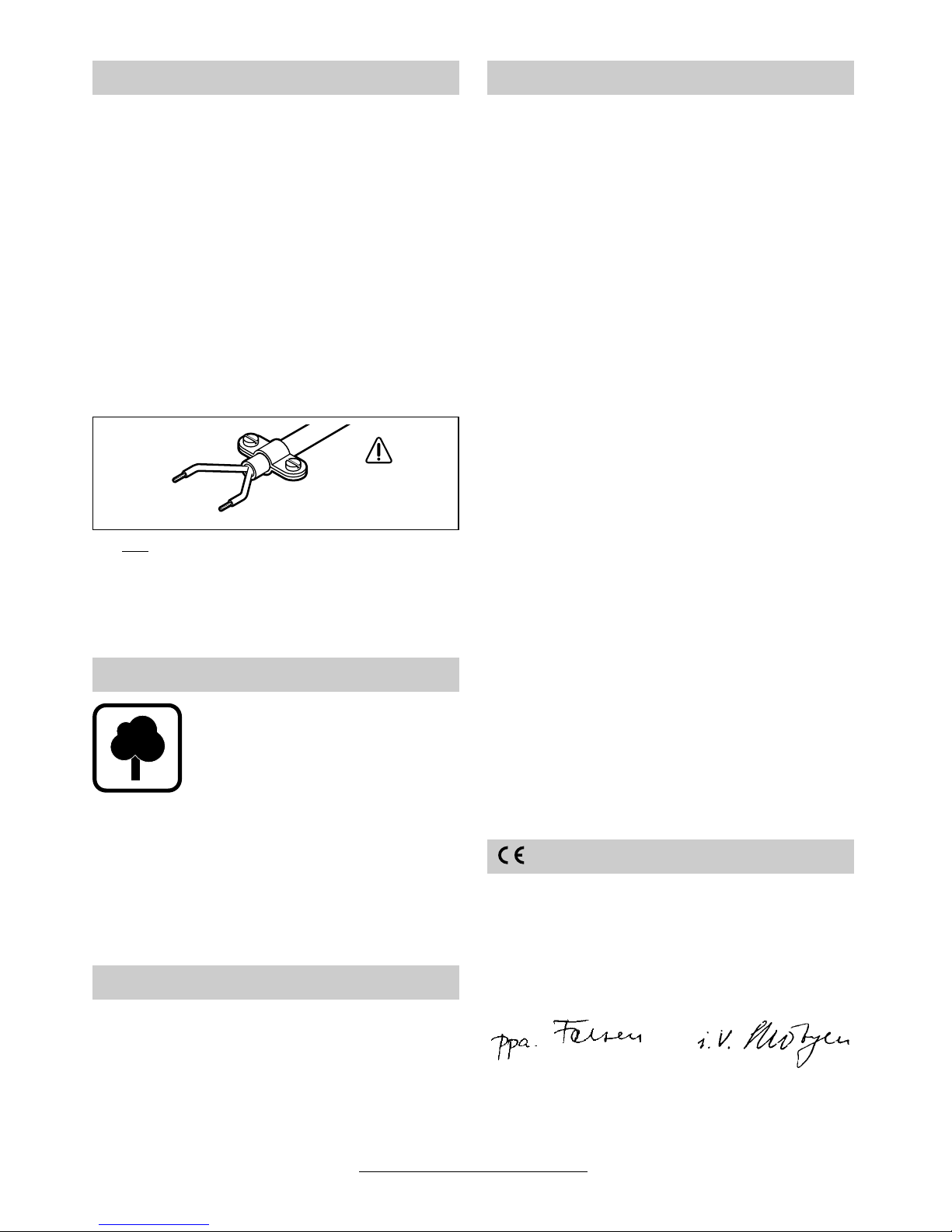
■ Beim Bohren Zusatzgriff 10 verwenden.
Der Zusatzgriff kann mit der Flügelschraube 9
rechts- oder linksseitig am Spindelhals montiert
werden.
Mit dem Tiefenanschlag
11 kann die Bohrtiefe
eingestellt werden.
Dazu die Taste
8
drücken und den Tiefenanschlag parallel bis auf Höhe der Bohrerspitze herausziehen. An der Skala (Pfeil) den abgelesenen Skalenwert abzüglich der gewünschten
Bohrtiefe
X
einstellen.
■
Vor allen Arbeiten am Gerät Netzstecker
ziehen.
Das Gerät besitzt zum einfachen und schnellen
Wechsel von Einsatzwerkzeugen/Bohrfutter eine
Bohrspindelarretierung, wodurch ein Festhalten
der Bohrspindel von Hand bzw. mit einem Werkzeug entfällt.
Dazu die Spindelarretiertaste
2
niederdrücken
und das Bohrfutter von Hand langsam weiterdrehen, bis die Bohrspindel spürbar einrastet und
das Bohrfutter blockiert.
Spindelarretiertaste nur bei Stillstand betätigen.
Das Bohrfutter öffnen, bis das Werkzeug eingesetzt werden kann. Das Werkzeug einsetzen.
Schnellspannbohrfutter (siehe Bild )
Das Bohrfutter mittels Spindelarretiertaste 2 blockieren und gedrückt halten. Das Bohrfutter soweit öffnen, bis das Werkzeug eingesetzt werden
kann.
Die Hülse des Schnellspannbohrfutters von
Hand bei gedrückter Spindelarretiertaste kräftig
zudrehen bis kein Überrasten („klick”) mehr hörbar ist. Das Bohrfutter wird damit automatisch
verriegelt.
Die Verriegelung löst sich wieder, wenn zum Entfernen des Werkzeuges die vordere Hülse in Gegenrichtung gedreht wird.
Vorsicht bei heißem Bohrfutter:
Bei längeren Arbeitsvorgängen, insbeson-
dere bei Schlagbohrarbeiten, kann sich das
Bohrfutter stark erwärmen. In diesem Fall
wird das Tragen von Schutzhandschuhen
empfohlen.
Zahnkranzbohrfutter (siehe Bild )
Mit dem Bohrfutterschlüssel 12 gleichmäßig in allen drei Bohrungen spannen.
Netzspannung beachten: Die Spannung der
Stromquelle muss mit den Angaben auf dem Typenschild des Gerätes übereinstimmen. Mit
230 V gekennzeichnete Geräte können auch an
220 V betrieben werden.
Ein-/Ausschalten
Zur Inbetriebnahme des Gerätes den Ein-/Ausschalter
5
drücken und gedrückt halten.
Die Maschine läuft je nach Druck auf
den Ein-/Ausschalter
5
mit variabler
Drehzahl zwischen 0 und Maximum.
Leichter Druck bewirkt eine kleine
Drehzahl und macht somit einen
sanften, kontrollierten Anlauf möglich. Das Gerät nicht so stark belasten, dass es zum Stillstand
kommt.
(PSB 600 RE/PSB 640 RE/
PSB 650 RE/PSB 700 RE)
Zum Feststellen den Ein-/Ausschalter 5 in gedrücktem Zustand mit dem Feststellknopf
4
arre-
tieren.
Zum
Ausschalten des Gerätes den Ein-/Aus-
schalter
5
loslassen bzw. drücken und loslassen.
Drehzahlvorwahl
(PSB 600 RE/PSB 640 RE/
PSB 650 RE/PSB 700 RE)
Mit dem Stellrad 6 lässt sich die benötigte Drehzahl (auch während des Laufes) vorwählen.
Zusatzgriff/Tiefenanschlag
Bohrspindelarretierung
Werkzeug einsetzen
A
Inbetriebnahme
B
6 • 2 609 932 184 • 02.07

Deutsch - 4
Zwei-Stufen-Schaltung (PSB 650-2)
Mit dem Ein-/Ausschalter 5 können zwei Dreh-
zahlbereiche vorgewählt werden. Nach Überschreiten eines spürbaren Druckpunktes schaltet
die Maschine von der ersten in die zweite Drehzahlstufe um:
Drehzahlstufe I: 2 500 min
-1
Drehzahlstufe II: 3 000 min
-1
Der Ein-/Ausschalter kann mittels Feststellknopf 4 in beiden Drehzahlstufen arretiert wer-
den.
Umschalten der Drehrichtung
(PSB 600 RE/PSB 640 RE/
PSB 650 RE/PSB 700 RE)
Den Drehrichtungsumschalter 7 nur bei Stillstand betätigen.
Mit dem Drehrichtungsumschalter 7 wird die
Drehrichtung der Maschine umgeschaltet. Bei
betätigtem Ein-/Ausschalter 5 ist dies jedoch
nicht möglich.
Drehrichtung rechts (siehe Bild )
Den Drehrichtungsumschalter nach links bis zum
Anschlag durchdrücken (Bohren, Schlagbohren,
Eindrehen von Schrauben etc.).
Drehrichtung links (siehe Bild )
Den Drehrichtungsumschalter nach rechts bis
zum Anschlag durchdrücken (Lösen bzw. Herausdrehen von Schrauben und Muttern).
Bohren, Schrauben und Schlagbohren
Bohren und Schrauben
Den Umschalter 3 auf das Symbol
„Bohren und Schrauben“ stellen.
Schlagbohren
Den Umschalter 3 auf das Symbol
„Schlagbohren“ stellen.
Der Umschalter 3 rastet spürbar ein und kann bei
laufender Maschine betätigt werden.
Den Innensechskantschlüssel mit dem kurzen
Schaft voran in das Bohrfutter einspannen.
Bohrfutter lösen (siehe Bild )
Die Maschine auf eine standfeste Unterlage
(z. B. Werkbank) legen. Die Bohrspindel mit der
Spindelarretiertaste 2 blockieren, die Maschine
festhalten und das Bohrfutter wie eine Schraube
durch Linksdrehen lösen (
➊). Ein festsitzendes
Bohrfutter wird durch einen Schlag auf den langen Schaft des Innensechskantschlüssels 14 gelöst.
Bohrfutter festziehen (siehe Bild )
Die Montage des Bohrfutters erfolgt in umgekehrter Reihenfolge (
➋
).
Das Bohrfutter muss mit einem Anzugsdrehmoment von ca. 30– 35 Nm festgezogen werden.
Die Vibrationsdämpfung 15 reduziert auftretende
Vibrationen.
Zum Auswechseln, Schraubendreher 16 an der
dafür vorgesehenen Aussparung am unteren Bereich der Grifffläche ansetzen und vorsichtig abhebeln.
Drehzahl bzw. Drehmoment sind vom Werkstoff
abhängig und können durch praktischen Versuch
ermittelt werden. Dabei stets mit der niedrigsten
Einstellung beginnen.
Nach längerem Arbeiten mit kleiner Drehzahl die
Maschine zur Abkühlung zirka 3 Minuten lang mit
maximaler Drehzahl im Leerlauf drehen lassen.
Um Fliesen zu bohren, den Umschalter 3 auf das
Symbol „Bohren und Schrauben“ stellen. Erst
nach Durchbohren der Fliese auf das Symbol
„Schlagbohren“ umschalten und mit Schlag arbeiten.
Bei Arbeiten in Beton, Gestein und Mauerwerk
sind Hartmetallbohrer erforderlich.
C
D
Bohrfutter wechseln
Vibrationsdämpfung
(siehe Bild )
(PSB 650 RE/PSB 700 RE)
Tipps
E
F
G
7 • 2 609 932 184 • 02.07
Deutsch - 5
■ Vor allen Arbeiten am Gerät Netzstecker ziehen.
■ Gerät und Lüftungsschlitze stets sauber halten, um gut und sicher zu arbeiten.
Sollte das Gerät trotz sorgfältiger Herstellungsund Prüfverfahren einmal ausfallen, ist die Reparatur von einer autorisierten Kundendienststelle
für Bosch-Elektrowerkzeuge ausführen zu lassen.
Bei allen Rückfragen und Ersatzteilbestellungen
bitte unbedingt die 10-stellige Bestellnummer laut
Typenschild des Gerätes angeben.
Rohstoffrückgewinnung statt Müllentsorgung
Gerät, Zubehör und Verpackung sollten einer
umweltgerechten Wiederverwertung zugeführt
werden.
Diese Anleitung ist aus chlorfrei gefertigtem Recycling-Papier hergestellt. Zum sortenreinen Recycling sind Kunststoffteile gekennzeichnet.
In Deutschland sind nicht mehr gebrauchsfähige
Geräte zum Recycling beim Handel abzugeben
oder (ausreichend frankiert) direkt einzuschicken
an:
Recyclingzentrum Elektrowerkzeuge
Osteroder Landstraße 3
37589 Kalefeld
Messwerte ermittelt entsprechend EN 50 144.
Der A-bewertete Geräuschpegel des Gerätes be-
trägt typischerweise: Schalldruckpegel 99 dB (A);
Schallleistungspegel 112 dB (A).
Gehörschutz tragen!
Die bewertete Beschleunigung beträgt typischerweise 16 m/s
2
.
www.bosch-pt.com
www.powertool-portal.de, das Internetportal
für Heimwerker und Gartenfreunde
www.dha.de, das komplette Service-Angebot
der Deutschen Heimwerker Akademie
Deutschland
Robert Bosch GmbH
Servicezentrum Elektrowerkzeuge
Zur Luhne 2
D-37589 Kalefeld
✆ Service:....................................... 01 80 - 3 35 54 99
Fax
............................................. +49 (0) 55 53 / 20 22 37
✆ Kundenberater: ...................... 01 80 - 3 33 57 99
Österreich
ABE Service GmbH
Jochen-Rindt-Straße 1
A-1232 Wien
✆ Service:..................................... +43 (0)1 / 61 03 80
Fax
................................................. +43 (0)1 / 61 03 84 91
✆ Kundenberater:............ +43 (0)1 / 797 22 3066
E-Mail: abe@abe-service.co.at
Schweiz
Robert Bosch AG
Kundendienst Elektrowerkzeuge
Industriestrasse 31
CH-8112 Otelfingen
✆ Service:................................. +41 (0)1 / 8 47 16 16
✆ Kundenberater:...... Grüne Nr. 0 800 55 11 55
Wir erklären in alleiniger Verantwortung, dass
dieses Produkt mit den folgenden Normen oder
normativen Dokumenten übereinstimmt:
EN 50 144 gemäß den Bestimmungen der Richtlinien 89/336/EWG, 98/37/EG.
Dr. Gerhard Felten Dr. Eckerhard Strötgen
Entwicklungsleiter Leiter Produktzulassung
Robert Bosch GmbH, Geschäftsbereich Elektrowerkzeuge
Änderungen vorbehalten
Wartung und Reinigung
Umweltschutz
Geräusch-/Vibrationsinformation
Service und Kundenberater
Konformitätserklärung
8 • 2 609 932 184 • 02.07

English - 1
Tool Specifications
Impact Drill PSB 600 RE PSB 640 RE PSB 650-2
Order number 0 603 386 6.. 0 603 386 6.. 0 603 386 0..
Rated power [W] 600 640 650
Output power [W] 340 340 340
No-load speed [rpm] 0–3 000 0 –3 000 2 500/3 000
Impact rate max. [bpm] 48 000 48 000 48 000
Drill Spindle Lock Button • • •
Speed Preselection • • –
Two-step switch – – •
Rotational direction switch • • –
Key chuck – – •
Keyless Chuck • • –
Vibration Damping – – –
Chuck clamping range [mm] 1.5–13 1.5–13 1.5–13
Drilling output:
- Steel max. [mm] 12 12 12
- Wood max. [mm] 30 30 30
- Concrete max. [mm] 16 16 16
Weight approx. [kg] 1.7 1.7 1.7
Protection class / II / II / II
Please observe the order number of your machine. The trade names of the individual machines may vary.
Impact Drill PSB 650 RE PSB 650 RE PSB 650 RE PSB 700 RE
Order number 0 603 386 5.. 0 603 386 6.. 0 603 386 1.. 0 603 386 4..
Rated power [W] 650 650 650 701
Output power [W] 340 340 340 360
No-load speed [rpm] 0–3 000 0–3 000 0–3 000 0–3 000
Impact rate max. [bpm] 48 000 48 000 48 000 48 000
Drill Spindle Lock Button • • • •
Speed Preselection • • • •
Two-step switch – – – –
Rotational direction switch • • • •
Key chuck • – – –
Keyless Chuck – • • •
Vibration Damping – – • •
Chuck clamping range [mm] 1.5–13 1.5–13 1.5–13 1.5–13
Drilling output:
- Steel max. [mm] 12 12 12 12
- Wood max. [mm] 30 30 30 30
- Concrete max. [mm] 16 16 16 16
Weight approx. [kg] 1.7 1.7 1.7 1.7
Protection class / II / II / II / II
Please observe the order number of your machine. The trade names of the individual machines may vary.
9 • 2 609 932 184 • 02.07
English - 2
1 Keyless chuck
2 Spindle lock
3 “Drilling/Impact Drilling” selector switch
4 Lock-on button for On/Off switch
5 On/Off switch
6 Thumbwheel for speed preselection
(PSB 600 RE/PSB 640 RE/PSB 650 RE/
PSB 700 RE)
7 Rotational direction switch
(PSB 600 RE/PSB 640 RE/PSB 650 RE/
PSB 700 RE)
8 Button for depth stop adjustment
9 Winged screw for auxiliary handle
adjustment
10 Auxiliary handle
11 Depth stop
12 Chuck key
13 Key chuck
14 Allen key*
15 Vibration damper
(PSB 650 RE/PSB 700 RE)
16 Screwdriver*
* Not all of the accessories illustrated or described are
included as standard delivery.
Working safely with this machine is possible only when the
operating and safety information
are read completely and the instructions contained therein are
strictly followed. In addition, the
general safety notes in the enclosed booklet must be observed.
■ Wear protective glasses and hearing protection.
■ For long hair, wear hair protection. Work only
with closely fitting clothes.
■ If the mains cable is damaged or cut through
while working, do not touch the cable but immediately pull the mains plug. Never use the
machine with a damaged cable.
■ Connect machines that are used in the open
via a residual current device (RCD) with an actuating current of 30 mA maximum. Use only
extension cables that are approved for outdoor
use.
■ Insert the mains plug only when the machine is
switched off.
■ Always direct the cable to the rear away from
the machine.
■ When drilling use the auxiliary handle 10.
■ Use appropriate detectors to determine if
utility lines are hidden in the work area or
call the local utility company for assistance.
Contact with electric lines can lead to fire and
electric shock. Damaging a gas line can lead
to explosion. Penetrating a water line causes
property damage or may cause an electric
shock.
■ If the drilling tool jams, it will cause the power
tool to jolt. If this occurs switch the machine off
immediately.
■ When working with the machine, always hold it
firmly with both hands and provide for a secure
stance.
■ Be careful when screwing in long screws; danger of sliding off.
■ When screwdriving, operate in first gear as
well as with a low speed.
■ Set the machine against the screw /nut only
when switched off.
■ Always switch the machine off and wait until it
has come to a standstill before placing it down.
■ Never allow children to use the machine.
■ Bosch is only able to ensure perfect operation
of the machine if the original accessories intended for it are used.
The machine is intended for impact drilling in
brick, concrete and stone as well as for drilling in
wood, metal, ceramics and plastics. Machines
with electronic control and right/left rotation are
also suitable for screwdriving and thread-cutting.
Machine Elements
For Your Safety
Intended Use
10 • 2 609 932 184 • 02.07

English - 3
■ When drilling use the auxiliary handle 10.
The auxiliary handle can be mounted on the left
or right side of the spindle collar, using the
winged screw 9.
The drilling depth can be set with the depth
stop 11.
For this, press button 8 and pull the depth stop
out parallel until it protrudes as far as the drill tip.
Adjust the read scale value minus the required
drilling depth X on the scale.
■ Before any work on the machine itself, pull
the mains plug.
For changing the tools or the drill chuck easily
and quickly, the machine has a drill spindle locking facility thus eliminating the need to hold the
drill spindle by hand or by using a tool.
For this purpose, press down the spindle lock
button 2 and turn the chuck slowly by hand until
the drill spindle can be felt to lock and the chuck
is blocked.
Press the spindle lock button only when at a
standstill.
Open the drill chuck until the tool can be inserted.
Insert the tool.
Keyless Chuck (see figure )
Lock the chuck by pressing the spindle locking
button 2 and hold pressed. Open the chuck wide
enough so that the tool can be inserted.
Pressing the spindle retention key, open the
sleeve of the chuck by turning it hard with your
hand until you don’t hear a “click” any longer. This
is the way to lock the chuck automatically.
The locking is released again when the front collar is turned in the opposite direction to remove
the tool.
Caution! The chuck may be very hot:
During longer working periods, especially
when impact drilling, the chuck can become
very hot. In this case we recommend wearing
protective gloves.
Key chuck (see figure )
Clamp evenly in all three holes with the chuck
key 12.
Observe correct mains voltage: The voltage of
the power source must agree with the voltage
specified on the nameplate of the machine.
Equipment marked with 230 V can also be connected to 220 V.
Switching On and Off
To start the machine, press the On/Off switch 5
and keep it depressed.
The machine runs with variable
speed between 0 and maximum, depending on the pressure applied to
the On /Off switch 5. Light pressure
results in a low rotational speed thus
allowing smooth, controlled starts.
Do not strain the machine so heavily
that it comes to a standstill.
(PSB 600 RE/PSB 640 RE/
PSB 650 RE/PSB 700 RE)
Lock the pushed On/Off switch 5 by pressing the
lock-on button 4.
To switch off the machine, release the On / Off
switch 5 or push and release it then.
Speed Preselection
(PSB 600 RE/PSB 640 RE/
PSB 650 RE/PSB 700 RE)
The required speed can be preselected with
thumbwheel 6 (also while running).
Auxiliary Handle/Depth Stop
Drill Spindle Lock Button
Inserting the Tool
A
Initial Operation
B
11 • 2 609 932 184 • 02.07
English - 4
Two-step switch (PSB 650-2)
Two speed ranges can be preselected with the
On/Off switch 5. The machine switches from the
first to the second speed step after a noticeable
pressure point has been exceeded:
Rotational speed step I: 2 500 rpm
Rotational speed step II: 3 000 rpm
The On/Off switch can be locked in either of the
speed steps with the lock-on button 4.
Reversing the Rotational Direction
(PSB 600 RE/PSB 640 RE/
PSB 650 RE/PSB 700 RE)
Operate the rotational direction switch 7 only
at a standstill.
The rotational direction switch 7 is used to re-
verse the rotational direction of the machine.
However, this is not possible with the On/Off
switch 5 actuated.
Right Rotation (see figure )
Press the rotational direction switch through to
the left stop (for drilling, impact drilling, driving
screws, etc.).
Left Rotation (see figure )
Press the rotational direction switch through to
the right stop (for loosening and unscrewing
screws and nuts).
Drilling, Screwdriving and
Impact Drilling
Drilling and Screwdriving
Set the selector switch 3 to the “drilling
and screwdriving” symbol.
Impact Drilling
Set the selector switch 3 to the “impact
drilling” symbol.
The selector switch 3 engages noticeably and
can be actuated with the machine running.
Clamp the short end of an Allen key in the chuck.
Loosening the Drill Chuck
(see figure )
Place the machine on a firm surface (e. g. workbench). Lock the drill spindle with the spindle
locking button 2, hold the machine firmly and
loosen the chuck by turning to the left in the same
way as for a screw (
➊). Loosen a tightly sitting
chuck by giving the long shaft of the Allen key 14
a sharp knock.
Tightening the Drill Chuck
(see figure )
The drill chuck is mounted in reverse order (➋).
The chuck must be tightened with a torque of
approx. 30–35 Nm.
The vibration damper 15 reduces occuring vibrations.
For changing, insert the screwdriver 16 into the
special groove designed for this purpose on the
lower part of the gripping surface. Carefully lever
off.
Speed as well as torque setting depend on the
material and can be determined by practical testing. Always start with the lowest setting.
After longer periods of working at low speed, allow the machine to cool down by running for approx. 3 minutes at maximum speed with no load.
For drilling in tiles, set the selector switch 3 to the
symbol “Drilling and Screwdriving”. Do not switch
over to the symbol “Impact Drilling” or work with
impact until after drilling through the tile.
Carbide tipped drill bits are required for jobs
when working in concrete, masonry and brick
wall.
C
D
Replacing the Drill Chuck
Vibration Damping
(see figure )
(PSB 650 RE/PSB 700 RE)
Tips
E
F
G
12 • 2 609 932 184 • 02.07
English - 5
■ Before any work on the machine itself, pull the
mains plug.
■ For safe and proper working, always keep the
machine and the ventilation slots clean.
If the machine should fail despite the care taken
in manufacturing and testing procedures, repair
should be carried out by an after-sales service
centre for Bosch power tools.
In all correspondence and spare parts orders,
please always include the 10-digit order number
given on the nameplate of the machine.
WARNING! Important instructions for connecting a new 3-pin plug to the 2-wire cable.
The wires in the cable are coloured according to
the following code:
Do not
connect the blue or brown wire to the
earth terminal of the plug.
Important: If for any reason the moulded plug is
removed from the cable of this machine it must be
disposed of safely.
Recycle raw materials instead of disposing as
waste
The machine, accessories and packaging should
be sorted for environmental-friendly recycling.
These instructions are printed on recycled paper
manufactured without chlorine. The plastic components are labelled for categorized recycling.
Measured values determined according to
EN 50 144.
Typically the A-weighted noise levels of the product are: sound pressure level: 99 dB (A); sound
power level: 112 dB (A).
Wear hearing protection!
The typical weighted acceleration is 16 m/s
2
.
www.bosch-pt.com
Great Britain
Robert Bosch Ltd. (B.S.C.)
P.O. Box 98
Broadwater Park
North Orbital Road
Denham-Uxbridge
GB-Middlesex UB 9 5HJ
✆ Service............................ +44 (0)18 95 / 83 87 82
✆ Advice line.................... +44 (0)18 95 / 83 87 91
Fax
............................................. +44 (0)18 95 / 83 87 89
Ireland
Beaver Distribution Ltd.
Greenhills Road
IRL-Tallaght-Dublin 24
✆ Service................................... +353 (0)1 / 414 9400
Fax
.................................................... +353 (0)1 / 459 8030
Australia
Robert Bosch Australia L.t.d.
RBAU/SPT2
1555 Centre Road
P.O. Box 66 Clayton
AUS-3168 Clayton/Victoria
✆ ............................................... +61 (0)1 / 800 804 777
Fax
............................................... +61 (0)1 / 800 819 520
www.bosch.com.au
E-Mail: CustomerSupportSPT@au.bosch.com
New Zealand
Robert Bosch Limited
14-16 Constellation Drive
Mairangi Bay
Auckland
New Zealand
✆ ..................................................... +64 (0)9 / 47 86 158
Fax
..................................................... +64 (0)9 / 47 82 914
We declare under our sole responsibility that
this product is in conformity with the following
standards or standardization documents:
EN 50 144 according to the provisions of the directives 89/336/EEC, 98/37/EC.
Dr. Gerhard Felten Dr. Eckerhard Strötgen
Senior Vice President Engineering Head of Product Certification
Robert Bosch GmbH, Geschäftsbereich Elektrowerkzeuge
Subject to change without notice
Maintenance and Cleaning
Environmental Protection
Noise/Vibration Information
strain relief
live = brown
neutral = blue
To be fitted
by qualified
professional only
Service and Customer Assistance
Declaration of Conformity
13 • 2 609 932 184 • 02.07

Français - 1
Caractéristiques techniques
Perceuse à percussion PSB 600 RE PSB 640 RE PSB 650-2
Référence 0 603 386 6.. 0 603 386 6.. 0 603 386 0..
Puissance absorbée [W] 600 640 650
Puissance débitée [W] 340 340 340
Régime à vide [tr/min] 0– 3 000 0–3 000 2 500/3 000
Fréquence de frappe max. [tr/min] 48 000 48 000 48 000
Blocage de la broche • • •
Présélection de la vitesse de
rotation
• • –
Commutation à deux vitesses – – •
Commutateur de sens de rotation • • –
Mandrin à couronne dentée – – •
Mandrin de perçage à serrage
rapide
• • –
Dispositif d’amortissement des
vibrations
– – –
Fixation du mandrin de perçage [mm] 1,5–13 1,5– 13 1,5–13
Puissance de perçage :
- Acier max. [mm] 12 12 12
- Bois max. [mm] 30 30 30
- Béton max. [mm] 16 16 16
Poids env. [kg] 1,7 1,7 1,7
Classe de protection / II / II / II
Faire attention au numéro de référence de la machine. Les désignations commerciales des différentes machines peuvent
varier.
Perceuse à percussion PSB 650 RE PSB 650 RE PSB 650 RE PSB 700 RE
Référence 0 603 386 5.. 0 603 386 6.. 0 603 386 1.. 0 603 386 4..
Puissance absorbée [W] 650 650 650 701
Puissance débitée [W] 340 340 340 360
Régime à vide [tr/min] 0– 3 000 0–3 000 0–3 000 0–3 000
Fréquence de frappe max. [tr/min] 48 000 48 000 48 000 48 000
Blocage de la broche • • • •
Présélection de la vitesse de
rotation
• • • •
Commutation à deux vitesses – – – –
Commutateur de sens de rotation • • • •
Mandrin à couronne dentée • – – –
Mandrin de perçage à serrage
rapide
– • • •
Dispositif d’amortissement des
vibrations
– – • •
Fixation du mandrin de perçage [mm] 1,5–13 1,5 –13 1,5–13 1,5–13
Puissance de perçage :
- Acier max. [mm] 12 12 12 12
- Bois max. [mm] 30 30 30 30
- Béton max. [mm] 16 16 16 16
Poids env. [kg] 1,7 1,7 1,7 1,7
Classe de protection / II / II / II / II
Faire attention au numéro de référence de la machine. Les désignations commerciales des différentes machines peuvent
varier.
14 • 2 609 932 184 • 02.07
Français - 2
1 Mandrin à serrage rapide
2 Touche de blocage de la broche
3 Commutateur
« Perçage/Perçage à percussion »
4 Bouton de verrouillage de l’interrupteur
Marche/Arrêt
5 Interrupteur Marche/Arrêt
6 Molette de présélection de la vitesse
(PSB 600 RE/PSB 640 RE/PSB 650 RE/
PSB 700 RE)
7 Commutateur du sens de rotation
(PSB 600 RE/PSB 640 RE/PSB 650 RE/
PSB 700 RE)
8 Touche pour le déplacement de la butée de
profondeur
9 Vis papillon pour réglage de la poignée
supplémentaire
10 Poignée supplémentaire
11 Butée de profondeur
12 Clé de mandrin
13 Mandrin à clé
14 Clé mâle pour vis à six pans creux*
15 Dispositif d’amortissement des vibrations
(PSB 650 RE/PSB 700 RE)
16 Tournevis*
* Les accessoires reproduits ou décrits ne sont pas
forcément fournis avec la machine.
Pour travailler sans risque avec
cet appareil, lire intégralement
au préalable les instructions
d’utilisation et les remarques
concernant la sécurité. Respecter scrupuleusement les indications et les consignes qui y sont
données. Respecter en plus les
indications générales de sécurité se trouvant dans le cahier
ci-joint.
■ Porter des lunettes de sécurité et une protection acoustique.
■ Les personnes portant les cheveux longs doivent se munir d’un protège-cheveux. Ne travailler qu’avec des vêtements près du corps.
■ Si le câble d’alimentation électrique est endommagé ou se rompt pendant le travail, ne
pas y toucher. Retirer immédiatement la fiche
du câble d’alimentation de la prise de courant.
Ne jamais utiliser un appareil dont le cordon
d’alimentation est endommagé.
■ Monter un disjoncteur différentiel (courant de
déclenchement : 30 mA max.) en amont des
appareils utilisés en plein air. N’utiliser qu’un
câble de rallonge électrique autorisé pour les
travaux à l’extérieur.
■ Ne brancher l’appareil que si celui-ci est en position « Arrêt ».
■ Toujours ramener les câbles à l’arrière de l’appareil.
■ Pour effectuer des travaux de perçage, utiliser
la poignée supplémentaire 10.
■ Utiliser des détecteurs appropriés afin de
déceler des conduites cachées ou consulter les entreprises d’approvisionnement locales.
Un contact avec des conduites d’électricité
peut provoquer un incendie ou un choc électrique. Un endommagement d’une conduite de
gaz peut provoquer une explosion. La perforation d’une conduite d’eau provoque des dégâts
matériels et peut provoquer un choc électrique.
■ Le blocage de l’outil de perçage provoque de
fortes réactions au niveau de l’appareil. Dans
ce cas-là, arrêter immédiatement l’appareil.
■ Pendant le travail avec cet appareil, le tenir
toujours fermement avec les deux mains.
Adopter une position stable et sûre.
■ Attention lors de la pose des vis longues : elles
peuvent glisser.
■ Visser en 1ère ou avec une vitesse de rotation
réduite.
■ N’appliquer l’appareil sur un écrou ou une vis
que lorsqu’il est à l’arrêt.
■ Avant de déposer l’appareil, toujours le mettre
hors fonctionnement et attendre l’arrêt total de
l’appareil.
■ Ne jamais permettre aux enfants d’utiliser cet
appareil.
■ Bosch ne peut garantir un fonctionnement impeccable que si les accessoires Bosch d’origine prévus pour cet appareil sont utilisés.
L’appareil est conçu pour les travaux de perçage
en frappe dans la brique, le béton et dans la
pierre naturelle ainsi que pour le perçage dans le
bois, le métal, la céramique et les matières plastiques. Les appareils avec réglage électronique
et rotation à droite/à gauche sont également appropriés pour le vissage et le filetage.
Eléments de la machine
Pour votre sécurité
Utilisation conformément à la
destination de l’appareil
15 • 2 609 932 184 • 02.07

Français - 3
■ Pour effectuer des travaux de perçage, uti-
liser la poignée supplémentaire 10.
La poignée supplémentaire peut être montée soit
à droite, soit à gauche du collet de la broche au
moyen de la vis papillon 9.
La butée de profondeur 11 permet de régler la
profondeur de perçage.
Pour cela, appuyer sur la touche 8 et tirer la butée de profondeur parallèlement jusqu’à la pointe
du foret. Régler la valeur relevée sur la graduation (flèche) en déduisant après avoir déduit la
profondeur de perçage X souhaitée.
■ Avant toute intervention sur l’appareil pro-
prement dit, toujours retirer la fiche du câble d’alimentation de la prise de courant.
Afin de changer facilement et rapidement les
outils et les mandrins, l’appareil est muni d’un
système de blocage de la broche qui évite de
maintenir la broche à la main ou à l’aide d’un
outil.
Appuyer sur la touche de blocage 2, continuer à
tourner lentement le mandrin à la main jusqu’à ce
que la broche s’encliquette de manière perceptible et que le mandrin soit bloqué.
N’appuyer sur la touche de blocage qu’à l’arrêt total de l’appareil.
Ouvrir le mandrin de perçage de sorte que l’outil
puisse être monté. Monter l’outil.
Mandrin de perçage à serrage rapide
(voir figure )
Bloquer le mandrin à l’aide de la touche de blocage 2 et maintenir celle-ci enfoncée. Ouvrir le
mandrin jusqu’à ce qu’il soit possible de monter
l’outil.
Bien visser la douille du mandrin à serrage rapide
en la tournant fortement à la main, la touche de
blocage de la broche étant appuyée, jusqu’à ce
qu’il n’y ait plus de déclic perceptible. Le mandrin
de perçage se trouve alors verrouillé automatiquement.
Pour déverrouiller et pour pouvoir ainsi enlever
l’outil, tourner dans le sens contraire la douille
avant.
Attention quand le mandrin de perçage est
chaud :
En cas de travaux assez longs, notamment
lors des travaux de perçage en percussion, le
mandrin de perçage risque de chauffer fortement. Dans ce cas-là, il est recommandé de
porter des gants de protection.
Mandrin à couronne dentée
(voir figure )
A l’aide de la clé de mandrin 12, serrer de ma-
nière régulière dans les trois alésages.
Tenir compte de la tension du secteur : La tension de la source de courant doit correspondre
aux indications figurant sur la plaque signalétique
de l’appareil. Les appareils fonctionnant sous
230 V peuvent également être exploités sous
220 V.
Mise en fonctionnement/Arrêt
Afin de mettre l’appareil en fonctionnement,
appuyer sur l’interrupteur Marche/Arrêt 5 et le
maintenir appuyé.
En fonction de la pression exercée
sur l’interrupteur Marche/Arrêt 5,
l’appareil fonctionne à une vitesse
comprise entre 0 et le maximum.
Une légère pression fait tourner
l’appareil à petite vitesse, ce qui
permet un démarrage précis et en
douceur. Ne pas trop solliciter l’appareil qui risque sinon de s’arrêter.
(PSB 600 RE/PSB 640 RE/
PSB 650 RE/PSB 700 RE)
Afin de le bloquer, bloquer l’interrupteur Marche/
Arrêt 5 dans cette position à l’aide du bouton de
blocage de fonctionnement 4.
Afin d’arrêter l’appareil, relâcher l’interrupteur
Marche/Arrêt 5 ou appuyer sur l’interrupteur et le
relâcher.
Présélection de la vitesse de rotation
(PSB 600 RE/PSB 640 RE/
PSB 650 RE/PSB 700 RE)
A l’aide de la molette de réglage 6, il est possible
de présélectionner la vitesse de rotation nécessaire (même pendant que l’appareil est en fonctionnement).
Poignée supplémentaire/
Butée de profondeur
Blocage de la broche
Mise en place de l’outil
A
Mise en service
B
16 • 2 609 932 184 • 02.07
Français - 4
Commutation à deux vitesses
(PSB 650-2)
A l’aide de l’interrupteur Marche/Arrêt 5, il est
possible de choisir entre deux plages de vitesse
de rotation différentes. Une fois le point de pression perceptible dépassé, l’appareil commute de
la première vitesse à la deuxième vitesse :
Vitesse de rotation I : 2 500 tr/min
Vitesse de rotation II : 3 000 tr/min
L’interrupteur Marche/Arrêt peut être bloqué
dans les deux plages de vitesse de rotation à
l’aide du bouton de blocage 4.
Inversion du sens de rotation
(PSB 600 RE/PSB 640 RE/
PSB 650 RE/PSB 700 RE)
N’actionner le commutateur du sens de rotation 7 qu’à l’arrêt total de l’appareil.
Le sens de rotation de l’appareil peut être modifié
à l’aide du commutateur du sens de rotation 7.
Cela n’est toutefois pas possible en actionnant
l’interrupteur Marche/Arrêt 5.
Rotation à droite (voir figure )
Pousser à fond le commutateur du sens de rotation vers la gauche (perçage, perçage à percussion, vissage, etc.).
Rotation à gauche (voir figure )
Repousser à fond le commutateur du sens de rotation vers la droite « Rotation à droite » (pour les
travaux de desserrage, de dévissage de vis et
d’écrous).
Perçage, vissage et perçage à
percussion
Perçage et vissage
Mettre le commutateur 3 sur le symbole
« Perçage et vissage ».
Perçage à percussion
Mettre le commutateur 3 sur le symbole
« Perçage à percussion ».
Le commutateur 3 s’encliquette de manière perceptible et il peut être actionné même pendant
que l’appareil est en marche.
Serrer la clé mâle coudée pour vis à six pans
creux avec le côté le plus court dans le mandrin
de serrage.
Desserrer le mandrin (voir figure )
Poser l’appareil sur un support stable (p. ex. établi). Bloquer la broche à l’aide de la touche de
blocage 2, maintenir l’appareil et dévisser le
mandrin en tournant vers la gauche comme si
c’était une vis (
➊). Un mandrin qui serait trop
serré peut être desserré par un léger coup sur le
côté le plus long de la clé mâle coudée pour vis à
six pans creux 14.
Serrer le mandrin (voir figure )
Pour monter le mandrin, procéder en sens inverse (
➋
).
Le mandrin de perçage doit être serré à un
couple de serrage de 30– 35 Nm environ.
Le dispositif pour l’amortissement des vibrations 15 réduit les vibrations se produisant lors du
travail.
Pour remplacer celle-ci, positionner le tournevis 16 sur l’encoche se trouvant sur la partie infé-
rieure et prévue à cet effet et la faire sortir avec
précaution.
La vitesse de rotation et le couple dépendent du
matériau à travailler et peuvent être déterminés
par des essais pratiques. Commencer toujours
avec le plus petit réglage.
Après avoir travaillé à une petite vitesse de rotation pendant une période relativement longue,
faire travailler l’appareil à vide à la vitesse de rotation maximale pendant une durée de 3 minutes
environ afin de le laisser refroidir.
Pour percer des carreaux de faïence, mettre le
commutateur 3 sur le symbole « perçage et vis-
sage ». Une fois le carreau de faïence percé, positionner le commutateur sur le symbole « perçage à percussion » et poursuivre le travail en
mode de perçage en frappe.
Des forets en carbure sont nécessaires pour les
travaux de perçage dans le béton, la pierre et la
maçonnerie.
C
D
Changement du mandrin
Dispositif d’amortissement des
vibrations (voir figure )
(PSB 650 RE/PSB 700 RE)
Conseils d’utilisation
E
F
G
17 • 2 609 932 184 • 02.07

Français - 5
■ Avant toute intervention sur l’appareil proprement dit, toujours retirer la fiche du câble d’alimentation de la prise de courant.
■ Pour obtenir un travail sûr et satisfaisant, nettoyer régulièrement l’appareil ainsi que ses
ouïes de refroidissement.
Si, malgré tous les soins apportés à la fabrication
et au contrôle de l’appareil, celui-ci devait avoir
un défaut, la réparation ne doit être confiée qu’à
une station de service après-vente agréée pour
outillage Bosch.
Pour toute demande de renseignements ou commande de pièces de rechange, nous préciser impérativement le numéro de référence à dix chiffres de la machine.
Récupération des matières premières plutôt
qu’élimination des déchets
Les machines, comme d’ailleurs leurs accessoires et emballages, doivent pouvoir suivre chacune une voie de recyclage appropriée.
Ce manuel d’instructions a été fabriqué à partir
d’un papier recyclé blanchi en l’absence de
chlore. Nos pièces plastiques ont ainsi été marquées en vue d’un recyclage sélectif des différents matériaux.
Valeurs de mesure obtenues conformément à la
norme européenne 50 144.
Les mesures réelles (A) des niveaux sonores de
la machine sont : intensité de bruit 99 dB (A). Niveau de bruit 112 dB (A).
Munissez-vous d’une protection acoustique !
L’accélération réelle mesurée est de 16 m/s
2
.
www.bosch-pt.com
France
Information par Minitel 11
Nom : Bosch Outillage
Loc : Saint Ouen
Dépt : 93
Robert Bosch France S.A.
Service Après-vente/Outillage
B.P. 67-50, Rue Ardoin
F-93402 St. Ouen Cedex
✆ Service conseil client,
Numéro Vert
.................................... 0 800 05 50 51
Belgique
Robert Bosch S.A.
After Sales Service Outillage
Rue Henri Genesse 1
BE-1070 Bruxelles
✆ ..................................................... +32 (0)2 / 525.50.29
Fax
..................................................... +32 (0)2 / 525.54.30
✆ Service conseil client..... +32 (0)2 / 525.53.07
E-Mail : Outillage.Gereedschappen@be.bosch.com
Suisse
Robert Bosch AG
Service après-vente/Outillage
Industriestrasse 31
CH-8112 Otelfingen
✆ .................................................... +41 (0)1 / 8 47 16 16
✆ Service conseil client,
Numéro Vert
.................................... 0 800 55 11 55
Nous déclarons sous notre propre responsabilité
que ce produit est en conformité avec les normes
ou documents normalisés suivants : EN 50 144
conformément aux réglementations 89/336/CEE,
98/37/CE.
Dr. Gerhard Felten Dr. Eckerhard Strötgen
Chef de bureau d’études Chef du service
Homologation de produit
Robert Bosch GmbH, Geschäftsbereich Elektrowerkzeuge
Sous réserve de modifications
Nettoyage et entretien
Instructions de protection de
l’environnement
Bruits et vibrations
Service Après-Vente
Déclaration de conformité
18 • 2 609 932 184 • 02.07

Español - 1
Características técnicas
Taladradora de percusión PSB 600 RE PSB 640 RE PSB 650-2
Número de pedido 0 603 386 6.. 0 603 386 6.. 0 603 386 0..
Potencia absorbida [W] 600 640 650
Potencia útil [W] 340 340 340
Revoluciones en vacío [min-1] 0 –3 000 0–3 000 2 500/3 000
Frecuencia de percusión máx. [min-1] 48 000 48 000 48 000
Retención del husillo de taladrar • • •
Preselección de revoluciones • • –
Selector de dos etapas – – •
Selector de sentido de giro • • –
Portabrocas de corona dentada – – •
Portabrocas de cierre rápido • • –
Amortiguador de vibraciones – – –
Capacidad de sujeción del
portabrocas
[mm] 1,5–13 1,5–13 1,5–13
Prestaciones de taladrado:
- Acero máx. [mm] 12 12 12
- Madera máx. [mm] 30 30 30
- Hormigón máx. [mm] 16 16 16
Peso aprox. [kg] 1,7 1,7 1,7
Clase de protección / II / II / II
Preste atención al nº de pedido de su máquina. Las denominaciones comerciales en ciertas máquinas pueden variar.
Taladradora de percusión PSB 650 RE PSB 650 RE PSB 650 RE PSB 700 RE
Número de pedido 0 603 386 5.. 0 603 386 6.. 0 603 386 1.. 0 603 386 4..
Potencia absorbida [W] 650 650 650 701
Potencia útil [W] 340 340 340 360
Revoluciones en vacío [min-1] 0 –3 000 0–3 000 0–3 000 0–3 000
Frecuencia de percusión máx. [min-1] 48 000 48 000 48 000 48 000
Retención del husillo de taladrar • • • •
Preselección de revoluciones • • • •
Selector de dos etapas – – – –
Selector de sentido de giro • • • •
Portabrocas de corona dentada • – – –
Portabrocas de cierre rápido – • • •
Amortiguador de vibraciones – – • •
Capacidad de sujeción del
portabrocas
[mm] 1,5–13 1,5–13 1,5–13 1,5–13
Prestaciones de taladrado:
- Acero máx. [mm] 12 12 12 12
- Madera máx. [mm] 30 30 30 30
- Hormigón máx. [mm] 16 16 16 16
Peso aprox. [kg] 1,7 1,7 1,7 1,7
Clase de protección / II / II / II / II
Preste atención al nº de pedido de su máquina. Las denominaciones comerciales en ciertas máquinas pueden variar.
19 • 2 609 932 184 • 02.07
Español - 2
1 Portabrocas de sujeción rápida
2 Botón de bloqueo de husillo
3 Selector “Taladrar/Taladrar con percusión”
4 Botón de enclavamiento para interruptor de
conexión/desconexión
5 Interruptor de conexión/desconexión
6 Rueda preselectora de revoluciones
(PSB 600 RE/PSB 640 RE/PSB 650 RE/
PSB 700 RE)
7 Selector de sentido de giro
(PSB 600 RE/PSB 640 RE/PSB 650 RE/
PSB 700 RE)
8 Tecla para ajuste del tope de profundidad
9 Tornillo de mariposa para ajuste de la
empuñadura adicional
10 Empuñadura adicional
11 Tope de profundidad
12 Llave de portabrocas
13 Portabrocas de corona dentada
14 Llave macho hexagonal*
15 Amortiguador de vibraciones
(PSB 650 RE/PSB 700 RE)
16 Destornillador*
* Los accesorios descritos e ilustrados no correspon-
den en parte al material que se adjunta
Solamente puede trabajar sin peligro con el aparato si lee íntegramente las instrucciones de manejo y las indicaciones de seguridad, ateniéndose estrictamente a
las recomendaciones allí comprendidas. Adicionalmente deberán respetarse las instrucciones
de seguridad generales comprendidas en el folleto adjunto.
■ Llevar gafas de protección y protectores auditivos.
■ Si tiene el pelo largo, recójaselo bajo una protección adecuada. Trabajar únicamente con
vestimenta ceñida al cuerpo.
■ Si llega a dañarse o cortarse el cable de red durante el trabajo, no tocar el cable, sino extraer
inmediatamente el enchufe de la red. No usar
jamás el aparato con un cable deteriorado.
■ Conectar los aparatos empleados en el exterior a través de un fusible diferencial ajustado
a una corriente de disparo de 30 mA máximo.
Utilizar cables de prolongación autorizados
para su uso en el exterior.
■ Conectar la máquina a la red únicamente estando desconectada.
■ Mantener el cable siempre detrás del aparato.
■ Al taladrar emplear la empuñadura adicio-
nal 10.
■ Utilice unos instrumentos de exploración
adecuados para detectar tuberías y cables
ocultos, o consulte a su compañía abastecedora local.
El contacto con cables eléctricos puede provocar un incendio o sacudida eléctrica. El deterioro de tuberías de gas puede producir una
explosión. La perforación de una tubería de
agua puede causar daños materiales o una
sacudida eléctrica.
■ Al bloquearse el útil de taladrar se obtiene un
par de reacción brusco en el aparato. En estos
casos, desconectarlo inmediatamente.
■ Trabajar siempre con el aparato sujetándolo
firmemente con ambas manos y manteniendo
una posición estable.
■ Cuidado al atornillar tornillos largos: peligro de
resbalar.
■ Al atornillar trabajar en la 1
a
velocidad o con
bajas revoluciones.
■ Aplicar el aparato, solamente estando desconectado, sobre la tuerca o tornillo.
■ Siempre desconectar y esperar a que se detenga el aparato, antes de depositarlo.
■ Jamás permita que los niños utilicen el aparato.
■ Bosch solamente puede garantizar el funcio-
namiento correcto del aparato si se utilizan los
accesorios originales previstos.
El aparato ha sido proyectado para taladrar con
percusión en ladrillo, hormigón y piedra, así
como para taladrar sin percutir en madera, metal,
cerámica y material sintético. Los aparatos con
regulación electrónica de giro a derechas e izquierdas son también adecuados para atornillar y
tallar roscas.
■ Al taladrar emplear la empuñadura adicional 10.
La empuñadura adicional puede montarse a la
derecha o izquierda del cuello del husillo con el
tornillo de mariposa 9.
Con el tope de profundidad 11 puede ajustarse la
profundidad de taladrado.
Elementos del aparato
Para su seguridad
Utilización reglamentaria
Empuñadura adicional/
tope de profundidad
20 • 2 609 932 184 • 02.07

Español - 3
Para ello, pulsar la tecla 8 y extraer paralela-
mente el tope de profundidad a la misma altura
de la punta de la broca. Restar la profundidad de
taladro deseada X al valor actual mostrado en la
escala (flecha) y ajustarla a este valor.
■ Antes de cualquier manipulación en el apa-
rato extraer el enchufe de la red.
Para el cambio simple y rápido de útil/portabrocas puede enclavarse en el aparato el husillo de
taladrar, lo que evita tener que sujetarlo con la
mano o herramienta.
Presionar para ello la tecla de enclavamiento 2 y
girar el portabrocas lentamente con la mano
hasta que el husillo quede enclavado de manera
perceptible, bloqueando así el portabrocas.
Accionar la tecla de enclavamiento solamente con el aparato detenido.
Abrir el portabrocas lo suficiente para poder insertar el útil. Introducir el útil.
Portabrocas de cierre rápido
(ver figura )
Sujetar el portabrocas con la tecla de enclavamiento 2 y mantenerla presionada. Abrir el por-
tabrocas lo suficiente para permitir la inserción
del útil.
Manteniendo presionado el botón de bloqueo del
husillo, girar firmemente a mano el casquillo del
portabrocas de cierre rápido hasta que no sea
perceptible ya más el ruido de carraca (“clic”).
Con ello se enclava automáticamente el portabrocas.
Para retirar el útil, girar el casquillo delantero en
sentido opuesto, para liberar así el mecanismo
de enclavamiento.
Precaución con el portabrocas caliente:
Al utilizar el aparato prolongadamente, y muy
especialmente al trabajar con percusión,
puede que el portabrocas se caliente fuertemente. En estos casos se recomienda ponerse guantes de protección.
Portabrocas de corona dentada
(ver figura )
Aplicar la llave del portabrocas 12 en cada uno
de los tres taladros y apretar uniformemente.
Cerciorarse de que la tensión de la red sea
correcta: La tensión de la fuente de energía
debe coincidir con las indicaciones en la placa de
características del aparato. Los aparatos marcados con 230 V pueden funcionar también a
220 V.
Conexión y desconexión
Para la puesta en marcha del aparato presionar
y mantener accionado el interruptor de conexión/
desconexión 5.
La máquina funciona con un número
de revoluciones variable entre 0 y
máximo según la presión ejercida
sobre el interruptor de conexión/
desconexión 5. Presionándolo lige-
ramente, se consigue un régimen de
giro reducido, lo que permite una
puesta en marcha suave y controlada. No solicitar el aparato de manera que llegue a detenerse.
(PSB 600 RE/PSB 640 RE/
PSB 650 RE/PSB 700 RE)
Para enclavar el interruptor de conexión/desconexión 5 mantenerlo apretado, y presionar el botón de enclavamiento 4.
Para desconectar el aparato soltar, o presionar
y soltar si estuviese enclavado, el interruptor de
conexión /desconexión 5.
Preselección de revoluciones
(PSB 600 RE/PSB 640 RE/
PSB 650 RE/PSB 700 RE)
Con la rueda de ajuste 6 puede seleccionarse el
número de revoluciones requerido (incluso durante la marcha del aparato).
Selector de dos etapas (PSB 650-2)
Con el interruptor de conexión/desconexión 5
pueden preseleccionarse dos revoluciones diferentes. Al presionar el interruptor hasta sobrepasar un punto de resistencia claramente perceptible, se conmuta la máquina del primer al segundo punto de revoluciones:
Etapa de velocidad I: 2 500 min
-1
Etapa de velocidad II: 3 000 min
-1
El interruptor de conexión/desconexión pueden
enclavarse en cada punto de revoluciones con el
botón de enclavamiento 4.
Retención del husillo de
taladrar
Montaje de la herramienta
A
B
Puesta en servicio
21 • 2 609 932 184 • 02.07

Español - 4
Conmutación del sentido de giro
(PSB 600 RE/PSB 640 RE/
PSB 650 RE/PSB 700 RE)
Accionar el selector de sentido de giro 7 solamente con el aparato detenido.
El selector de sentido de giro 7 sirve para invertir
el sentido de giro de la máquina. Ello no es posible, sin embargo, si se mantiene presionado el
interruptor de conexión/desconexión 5.
Dirección de giro a derechas (ver figura )
Presionar hasta el tope hacia la izquierda el selector de sentido de giro (taladrar, taladrar con
percutor, atornillar, etc.).
Dirección de giro a izquierdas (ver figura )
Presionar a tope hacia la derecha el selector de
sentido de giro (para aflojar o desenroscar tornillos y tuercas).
Taladrar, atornillar y taladrar con
percusión
Taladrar y atornillar:
Colocar el conmutador 3 sobre el sím-
bolo “Taladrar y atornillar”.
Taladrar con percusión
Colocar el conmutador 3 sobre el sím-
bolo “Taladrar con percusión”.
El conmutador 3 enclava de forma perceptible y
puede accionarse con la máquina en marcha.
Fijar el extremo corto de la llave macho hexagonal en el portabrocas.
Desmontaje del portabrocas
(ver figura )
Apoyar la máquina sobre una base de asiento rígida (p. ej. un banco de trabajo). Bloquear el husillo de taladrar con la tecla de enclavamiento 2,
sujetar la máquina y aflojar el portabrocas girándolo hacia la izquierda igual que un tornillo (
➊).
Un portabrocas fuertemente sujeto, se afloja aplicando un golpe sobre el extremo largo de la llave
macho hexagonal 14.
Montaje del portabrocas (ver figura )
El montaje del portabrocas se realiza en el orden
inverso (
➋
).
El portabrocas deberá apretarse con un par
de apriete de 30– 35 Nm aprox.
El amortiguador de vibraciones 15 atenúa las vibraciones producidas.
Para sustituirlo, aplicar el atornillador 16 en la
muesca inferior del elemento y sacarlo haciendo
palanca con él.
Las revoluciones o el par de giro dependen del
material a trabajar y deben determinarse probando. Para ello, comenzar siempre con el ajuste
más bajo.
Después de trabajar prolongadamente a bajas
revoluciones, dejar funcionar la máquina 3 minutos aprox. a revoluciones máximas en vacío para
refrigerarlo.
Para taladrar azulejos girar el selector 3 a la posición “Taladrar y atornillar”. Solamente después
de haber traspasado el azulejo, seleccionar el
símbolo “Taladrar con percusión” para continuar
trabajando con percusión.
Al realizar trabajos en hormigón, piedra y muro
de ladrillo deben utilizarse brocas de metal duro.
■ Antes de cualquier manipulación en el aparato
extraer el enchufe de la red.
■ Mantener siempre limpios el aparato y las rejillas de refrigeración para poder trabajar con
seguridad.
Si a pesar de los esmerados procesos de fabricación y control, el aparato llegase a averiarse, la
reparación deberá encargarse a un taller de servicio autorizado para herramientas eléctricas
Bosch.
Al realizar consultas o solicitar piezas de repuesto, es imprescindible indicar siempre el número de pedido de 10 cifras que figura en la
placa de características del aparato.
Cambio de portabrocas
C
D
E
F
Amortiguador de vibraciones
(ver figura )
(PSB 650 RE/PSB 700 RE)
Consejos prácticos
Mantenimiento y limpieza
G
22 • 2 609 932 184 • 02.07

Español - 5
Recuperación de materias primas en lugar de
producir desperdicios.
El aparato, los accesorios y el embalaje debieran
someterse a un proceso de recuperación que
respete el medio ambiente.
Estas instrucciones se han impreso sobre papel
reciclado sin la utilización de cloro. Para efectuar
un reciclaje selectivo se han identificado las piezas de plástico.
Determinación de los valores de medición según
norma EN 50 144.
El nivel de ruido típico del aparato corresponde a:
nivel de presión de sonido 99 dB (A); nivel de potencia de sonido 112 dB (A).
¡Usar protectores auditivos!
El nivel de vibraciones típico es de16 m/s
2
.
www.bosch-pt.com
España
Robert Bosch España, S.A.
Departamento de ventas
Herramientas Eléctricas
C/Hermanos García Noblejas, 19
E-28037 Madrid
✆ Asesoramiento al cliente.... +34 901 11 66 97
Fax
........................................................... +34 91 327 98 63
Venezuela
Robert Bosch S.A.
Final Calle Vargas. Edf. Centro Berimer P.B.
Boleita Norte
Caracas 107
✆ ..................................................... +58 (0)2 / 207 45 11
México
Robert Bosch S.A. de C.V.
✆ Interior:............................ +52 (0)1 / 800 250 3648
✆ D.F.:......................................... +52 (0)1 / 5662 8785
E-Mail: arturo.fernandez@mx.bosch.com
Argentina
Robert Bosch Argentina S.A.
Córdoba 5160
1414 Buenos Aires (Capital Federal)
Atención al Cliente
✆ ................................................. +54 (0)810 / 555 2020
E-Mail: herramientas.bosch@ar.bosch.com
Perú
Autorex Peruana S.A.
República de Panamá 4045,
Lima 34
✆ ...................................................... +51 (0)1 / 475-5453
E-Mail: vhe@autorex.com.pe
Chile
EMASA S.A.
Irarrázaval 259 – Ñuñoa
Santiago
✆ ....................................................... +56 (0)2 / 520 3100
E-Mail: emasa@emasa.cl
Declaramos bajo nuestra sola responsabilidad
que este producto está en conformidad con las
normas o documentos normalizados siguientes: EN 50 144 de acuerdo con las regulaciones 89/336/CEE, 98/37/CE.
Dr. Gerhard Felten Dr. Eckerhard Strötgen
Director de Desarrollo Director de Homologación
de Producto
Robert Bosch GmbH, Geschäftsbereich Elektrowerkzeuge
Reservado el derecho de modificaciones
Protección del medio ambiente
Información sobre ruidos y
vibraciones
Servicio técnico y asistencia
al cliente
Declaración de conformidad
23 • 2 609 932 184 • 02.07

Português - 1
Dados técnicos do aparelho
Berbequim de percussão PSB 600 RE PSB 640 RE PSB 650-2
N° de encomenda 0 603 386 6.. 0 603 386 6.. 0 603 386 0..
Potência nominal absorvida [W] 600 640 650
Potência útil [W] 340 340 340
Rotações em vazio [min-1] 0 –3 000 0– 3 000 2 500/3 000
Nº de impactos máx. [/min] 48 000 48 000 48 000
Bloqueio de porta-brocas • • •
Pré-selecção de número de
rotação
• • –
Comutação de dois níveis – – •
Comutador da direcção de
rotações
• • –
Bucha de coroa dentada – – •
Bucha de aperto rápido • • –
Atenuação de vibrações – – –
Capacidade do mandril de
brocas
[mm] 1,5–13 1,5–13 1,5–13
Capacidade de perfuração:
- Aço máx. [mm] 12 12 12
- Madeira máx. [mm] 30 30 30
- Concreto máx. [mm] 16 16 16
Peso aprox. [kg] 1,7 1,7 1,7
Classe de protecção / II / II / II
Por favor observar o número de encomenda da sua máquina. A designação comercial de diversas máquinas pode variar.
Berbequim de percussão PSB 650 RE PSB 650 RE PSB 650 RE PSB 700 RE
N° de encomenda 0 603 386 5.. 0 603 386 6.. 0 603 386 1.. 0 603 386 4..
Potência nominal absorvida [W] 650 650 650 701
Potência útil [W] 340 340 340 360
Rotações em vazio [min-1] 0 –3 000 0–3 000 0–3 000 0–3 000
Nº de impactos máx. [/min] 48 000 48 000 48 000 48 000
Bloqueio de porta-brocas • • • •
Pré-selecção de número de
rotação
• • • •
Comutação de dois níveis – – – –
Comutador da direcção de
rotações
• • • •
Bucha de coroa dentada • – – –
Bucha de aperto rápido – • • •
Atenuação de vibrações – – • •
Capacidade do mandril de
brocas
[mm] 1,5–13 1,5–13 1,5–13 1,5–13
Capacidade de perfuração:
- Aço máx. [mm] 12 12 12 12
- Madeira máx. [mm] 30 30 30 30
- Concreto máx. [mm] 16 16 16 16
Peso aprox. [kg] 1,7 1,7 1,7 1,7
Classe de protecção / II / II / II / II
Por favor observar o número de encomenda da sua máquina. A designação comercial de diversas máquinas pode variar.
24 • 2 609 932 184 • 02.07

Português - 2
1 Mandril de brocas de fixação rápida
2 Tecla de travamento de veio
3 Comutador “Furar/furar com percussão”
4 Botão de travamento para o interruptor
de ligar/desligar
5 Interruptor de ligar/desligar
6 Rodela de ajuste do número de rotações
(PSB 600 RE/PSB 640 RE/PSB 650 RE/
PSB 700 RE)
7 Comutador da direcção de rotações
(PSB 600 RE/PSB 640 RE/PSB 650 RE/
PSB 700 RE)
8 Tecla para reajuste do esbarro de
profundidade
9 Parafuso de orelhas para o ajuste do punho
adicional
10 Punho adicional
11 Esbarro de profundidade
12 Chave de mandril de brocas
13 Mandril de brocas de coroa dentada
14 Chave de interior sextavado*
15 Atenuação de vibrações
(PSB 650 RE/PSB 700 RE)
16 Chave de fenda*
* Os acessórios ilustrados e descritos nas instruções
de serviço nem sempre são abrangidos pelo conjunto
de fornecimento!
Um trabalho seguro com o aparelho só é possível após ter lido
completamente as instruções de
serviço e as indicações de segurança e após observar rigorosamente as indicações nelas contidas. Adicionalmente deverá seguir as indicações gerais de
segurança que se encontram no
caderno em anexo.
■ Usar óculos de protecção e protecção para os
ouvidos.
■ Utilizar uma protecção para cabelos no caso
de cabelos compridos. Trabalhar exclusivamente com roupas justas.
■ Caso o cabo de rede for danificado ou cortado
durante o trabalho, não toque no cabo. Tire
imediatamente a ficha da tomada. Jamais utilizar o aparelho com um cabo danificado.
■ Aparelhos que forem utilizados ao ar livre devem ser ligados através de um interruptor de
protecção contra corrente de falha (FI) com no
máximo 30 mA de corrente de activação. Utilizar apenas um cabo de extensão apropriado
para a utilização ao ar livre.
■ A ficha só deve ser introduzida na tomada com
a máquina desligada.
■ Conduzir o cabo sempre por detrás da máquina.
■ Ao furar, deverá utilizar o punho adicional 10.
■ Utilize aparelhos detectores apropriados
para detectar cabos de alimentação ou
peça apoio da sua firma de abastecimento.
O contacto com cabos eléctricos pode provocar incêndio e choque eléctrico. O dano de
uma linha de gás pode levar a uma explosão.
Uma perfuração de um tubo de água provoca
um dano material ou pode provocar um choque eléctrico.
■ O bloqueio da broca leva à uma força de reacção intermitente do aparelho. Neste caso deverá desligar imediatamente o aparelho.
■ Ao trabalhar com o aparelho, segure-o sempre
com ambas as mãos e mantenha uma posição
firme.
■ Cuidado ao atarraxar parafusos compridosperigo de escorregamento.
■ Ao aparafusar, trabalhe na primeira marcha
ou com número de rotações reduzido.
■ Apenas apoiar o aparelho desligado sobre a
porca/parafuso.
■ Sempre desligar o aparelho antes de depositá-la e aguardar até que o aparelho páre
completamente.
■ Jamais deverá permitir que crianças utilizem
este aparelho.
■ A Bosch só pode assegurar um funcionamento perfeito do aparelho, se para este aparelho foram utilizados acessórios originais previstos para tal.
O aparelho é determinado para furar com percussão em tijolos, betão e pedras, assim como
para furar em madeira, metal, cerâmica e plástico. Aparelhos com regulação electrónica e marcha a direita/esquerda também são apropriados
para aparafusar e cortar roscas.
Elementos do aparelho
Para sua segurança
Utilização de acordo com as
disposições
25 • 2 609 932 184 • 02.07

Português - 3
■ Ao furar, deverá utilizar o punho adicio-
nal 10.
O punho adicional pode ser montado com o parafuso de orelhas 9, na direita ou na esquerda da
gola do veio.
A profundidade de perfuração pode ser regulada
através do esbarro de profundidade 11.
Para isto deverá premir a tecla 8 e puxar o es-
barro de profundidade paralelamente, até a altura da ponta da broca. Ajustar na escala (seta),
o valor de escala lido, reduzido pela profundidade de perfuração desejada X.
■ Tirar a ficha da tomada antes do todos os
trabalhos no aparelho.
Para uma fácil e rápida substituição de ferramentas/bucha, o aparelho possui um bloqueio de
porta-brocas. Assim não é mais necessário segurar o porta-brocas com a mão ou com uma ferramenta.
Para isto é necessário premir a tecla de bloqueio 2 e girar lentamente a bucha com a mão,
até que o porta-brocas trave nítidamente e a bucha esteja bloqueada.
Apenas accionar a tecla de bloqueio quando
o aparelho estiver parado.
Abrir a o mandril de brocas, até poder introduzir
a ferramenta. Introduzir a ferramenta.
Bucha de aperto rápido (veja figura )
Bloquear a bucha com a tecla de bloqueio 2 e
manter a tecla premida. Abrir a bucha, até que a
ferramenta possa ser introduzida.
Atarraxar manualmente a bucha do mandril de
brocas de aperto rápido com a tecla de travamento do veio premida, até que não possa ouvir
mais nenhum som de escapamento por
cima (“clic”). Desta forma o mandril de brocas é
travado automaticamente.
O bloqueio solta-se, girando a manga anterior no
sentido contrário, ao tirar novamente a ferramenta.
Cuidado com o mandril de brocas quente:
Durante prolongados processos de trabalho,
principalmente durante trabalhos de perfuração com percussão, pode ser que o mandril
de brocas seja extremamente aquecido.
Neste caso é recomendável utilizar luvas de
protecção.
Bucha de coroa dentada
(veja figura )
Apertar uniformemente em todos os três orifícios
com a chave de mandril de brocas 12.
Tenha em atenção a tensão de rede: A tensão
da fonte de corrente deve coincidir com as indicações no logotipo do aparelho. Aparelhos com
a indicação de 230 V também podem ser operados com 220 V.
Ligar e desligar
Pressionar o interruptor de ligar / desligar 5 para
colocar o aparelho em funcionamento e man-
ter pressionado.
De acordo com a pressão exercida
sobre o interruptor ligar / desligar 5,
a máquina trabalha com velocidade
variável entre 0 e velocidade máxima. Uma leve pressão tem por resultado um número reduzido de rotações e permite, assim, um arranque suave e controlado. O aparelho
não deve ser demasiadamente carregado, de modo que possa parar.
(PSB 600 RE/PSB 640 RE/
PSB 650 RE/PSB 700 RE)
Para fixar, deverá travar o interruptor de ligar /
desligar 5 com o botão de fixação 4 enquanto es-
tiver premido.
Para desligar o aparelho, deverá soltar o interruptor de ligar/ desligar 5 ou premir e soltar de
novo.
Pré-selecção de número de rotação
(PSB 600 RE/PSB 640 RE/
PSB 650 RE/PSB 700 RE)
Com a roda de ajuste 6 é possível pré-seleccionar o número de rotações necessário (mesmo
durante o funcionamento).
Punho adicional/Esbarro de
profundidade
Bloqueio de porta-brocas
Colocar a ferramenta
A
Colocação em funcionamento
B
26 • 2 609 932 184 • 02.07

Português - 4
Comutação de dois níveis (PSB 650-2)
Com o interruptor de ligar-desligar 5 podem ser
pré-seleccionadas duas faixas de números de rotações. Após ultrapassar um perceptível ponto
de pressão, a máquina comuta do primeiro nível
para o segundo nível de número de rotação:
Nível de número de rotação I: 2 500 min
-1
Nível de número de rotação II: 3 000 min
-1
O interruptor de ligar-desligar pode ser travado
em ambos os níveis de números de rotação através do botão de fixação 4.
Alteração do sentido de rotação
(PSB 600 RE/PSB 640 RE/
PSB 650 RE/PSB 700 RE)
Alterar o sentido de rotações 7 somente
quando a máquina estiver parada.
Com o comutador de sentido de rotação 7 é comutado o sentido de rotação da máquina. Se no
entanto o interruptor de ligar/desligar 5 estiver
accionado, isto não será possível.
Rotação para a direita (veja figura )
Premir o comutador de sentido de rotação completamente para a esquerda (furar, furar com
percussão apertar parafusos etc.).
Rotação para a esquerda (veja figura )
Premir o comutador de sentido de rotação completamente para a direita (soltar ou desapertar
parafusos e porcas).
Furar, aparafusar e furar com
percussão
Furar
Colocar o comutador 3 sobre o símbolo
“Furar e aparafusar”.
Furar com percussão
Para colocar o comutador 3 sobre o
símbolo “Furar com percussão”.
O comutador 3 engata sensívelmente e pode ser
accionado durante o funcionamento da máquina.
Introduzir uma chave de sextavado interno na
bucha, com o lado curto para frente.
Soltar a bucha (veja figura )
Apoiar a máquina sobre uma base firme (p. ex.
bancada de trabalho). Bloquear o porta-brocas
com a tecla de bloqueio 2, segurar a máquina e
soltar a bucha como um parafuso, girando para a
esquerda (
➊). Uma bucha muito presa pode ser
afrouxada através de uma leve pancada na haste
longa da chave de sextavado interno 14.
Apertar a bucha (veja figura )
A montagem da bucha é efectuada em sequência oposta (
➋
).
O mandril de brocas deve ser apertado com
um binário de arranque de aprox. 30 – 35 Nm.
A atenuação de vibrações 15 reduz as vibrações.
Para substituir, deverá introduzir a chave de
fenda 16 no respectivo entalhe na área da super-
fície do punho e abrir com cuidado.
O número de rotação e o binário dependem do
material a ser trabalhado e podem ser averiguados através de um ensaio prático. Comece sempre com o ajuste mais baixo.
Após trabalhar por tempo prolongado com um
número de rotações reduzido, deverá permitir
que a máquina funcione durante aproximadamente 3 minutos com máximo número de rotações, para que possa arrefecer.
Para furar em azulejos, deverá colocar o comutador 3 sobre o símbolo “Furar e aparafusar”. Apenas após perfurar o azulejo é que deverá comutar para o símbolo “Furar com percussão” e trabalhar com percussão.
Para trabalhos em betão, pedras e muramentos
são necessárias brocas de metal duro.
C
D
Substituir a bucha
Atenuação de vibrações
(veja figura )
(PSB 650 RE/PSB 700 RE)
Recomendações
E
F
G
27 • 2 609 932 184 • 02.07

Português - 5
■ Tirar a ficha da tomada antes do todos os trabalhos no aparelho.
■ Sempre manter o aparelho e as aberturas de
ventilação limpas, para trabalhar bem e de
forma segura.
Caso o aparelho venha a apresentar falhas, apesar de cuidadosos processos de fabricação e de
controlo de qualidade, deve ser reparado em um
serviço técnico autorizado para aparelhos eléctricos Bosch.
No caso de informações e encomendas de acessórios, indique por favor sem falta o número de
encomenda de 10 algarismos do aparelho!
Reciclagem de matérias primas em vez de eliminação de lixo
Recomenda-se sujeitar o aparelho, os acessórios e a embalagem à uma reutilização ecológica.
Estas instruções foram manufacturadas com papel reciclável isento de cloro. Para efeitos de
uma reciclagem específica, as peças de plástico
dispõem de uma respectiva marcação.
Valores de medida de acordo com EN 50 144.
O nível de ruído avaliado A do aparelho é tipica-
mente: Nível de pressão acústica 99 dB (A). Nível de potência acústica 112 dB (A).
Utilize protectores auriculares!
A aceleração avaliada é tipicamente de 16 m/s
2
.
www.bosch-pt.com
Portugal
Robert Bosch LDA
Avenida Infante D. Henrique
Lotes 2E-3E
P-1800 Lisboa
✆ .................................................... +351 21 / 8 50 00 00
Fax
.................................................... +351 21 / 8 51 10 96
Brasil
Robert Bosch Ltda.
Caixa postal 1195
13065-900 Campinas
✆ .............................................................. 0800 / 70 45446
E-Mail: sac@bosch-sac.com.br
Declaramos sob nossa exclusiva responsabilidade que este producto cumpre as seguintes normas ou documentos normativos: EN 50 144 conforme as disposições das directivas 89/336/CEE,
98/37/CE.
Dr. Gerhard Felten Dr. Eckerhard Strötgen
Director do dept. de Director da homologação
desenvolvimento de produtos
Robert Bosch GmbH, Geschäftsbereich Elektrowerkzeuge
Reservado o direito a modificações
Manutenção e conservação
Protecção do meio-ambiente
Informações sobre ruído e
vibrações
Serviço
Declaração de conformidade
28 • 2 609 932 184 • 02.07

Italiano - 1
Dati tecnici
Trapano battente PSB 600 RE PSB 640 RE PSB 650-2
Codice di ordinazione 0 603 386 6.. 0 603 386 6.. 0 603 386 0..
Potenza assorbita nominale [W] 600 640 650
Potenza resa [W] 340 340 340
Numero di giri a vuoto [g/min] 0– 3 000 0–3 000 2 500/3 000
Numero colpi mass. [c.pi/min] 48 000 48 000 48 000
Bloccaggio alberino filettato • • •
Preselezione numero di giri • • –
Comando a due stadi – – •
Commutatore per la
reversibilità
• • –
Mandrino a cremagliera – – •
Mandrino a serraggio veloce • • –
Ammortizzazione delle
vibrazioni
– – –
Apertura mandrino [mm] 1,5–13 1,5– 13 1,5–13
Diametro massimo forabile:
- Acciaio mass. [mm] 12 12 12
- Legno mass. [mm] 30 30 30
- Calcestruzzo mass. [mm] 16 16 16
Peso ca. [kg] 1,7 1,7 1,7
Classe protezione / II / II / II
Si prega di tenere sempre in considerazione il codice d’ordine della Vostra macchina. Le descrizioni commerciali di singole
macchine possono variare.
Trapano battente PSB 650 RE PSB 650 RE PSB 650 RE PSB 700 RE
Codice di ordinazione 0 603 386 5.. 0 603 386 6.. 0 603 386 1.. 0 603 386 4..
Potenza assorbita nominale [W] 650 650 650 701
Potenza resa [W] 340 340 340 360
Numero di giri a vuoto [g/min] 0– 3 000 0–3 000 0–3 000 0–3 000
Numero colpi mass. [c.pi/min] 48 000 48 000 48 000 48 000
Bloccaggio alberino filettato • • • •
Preselezione numero di giri • • • •
Comando a due stadi – – – –
Commutatore per la
reversibilità
• • • •
Mandrino a cremagliera • – – –
Mandrino a serraggio veloce – • • •
Ammortizzazione delle
vibrazioni
– – • •
Apertura mandrino [mm] 1,5–13 1,5– 13 1,5–13 1,5–13
Diametro massimo forabile:
- Acciaio mass. [mm] 12 12 12 12
- Legno mass. [mm] 30 30 30 30
- Calcestruzzo mass. [mm] 16 16 16 16
Peso ca. [kg] 1,7 1,7 1,7 1,7
Classe protezione / II / II / II / II
Si prega di tenere sempre in considerazione il codice d’ordine della Vostra macchina. Le descrizioni commerciali di singole
macchine possono variare.
29 • 2 609 932 184 • 02.07

Italiano - 2
1 Mandrino autoserrante
2 Tasto di bloccaggio dell’alberino
3 Selettore «Foratura/Foratura battente»
4 Pulsante di arresto per interruttore avvio/arresto
5 Interruttore di avvio/arresto
6 Rotellina di selezione numero giri
(PSB 600 RE/PSB 640 RE/PSB 650 RE/
PSB 700 RE)
7 Commutatore per la reversibilità
(PSB 600 RE/PSB 640 RE/PSB 650 RE/
PSB 700 RE)
8 Pulsante per l’impostazione della battuta di
profondità
9 Vite ad alette per la regolazione
dell’impugnatura supplementare
10 Impugnatura supplementare
11 Asta di profondità
12 Chiave di serraggio per mandrini
13 Mandrino a cremagliera
14 Chiave a brugola*
15 Ammortizzazione delle vibrazioni
(PSB 650 RE/PSB 700 RE)
16 Cacciavite*
* Gli accessori illustrati o descritti nelle istruzioni per
l’uso non sono sempre compresi nella fornitura!
È possibile lavorare con la macchina senza incorrere in pericoli
soltanto dopo aver letto completamente le istruzioni per l’uso e
l’opuscolo avvertenze per la sicurezza e seguendo rigorosamente
le istruzioni in essi contenute.
Inoltre vanno rispettate anche le
generali istruzioni di sicurezza riportate nell’opuscolo allegato.
■ Portare occhiali e cuffie di protezione.
■ In caso di capelli lunghi è necessario portare
un’adatta protezione per i capelli. Lavorare
soltanto con abiti adatti ed aderenti al corpo.
■ Se durante un’operazione di lavoro viene danneggiato oppure troncato il cavo dell’alimentazione di rete, non toccare il cavo ma estrarre
immediatamente la spina dalla presa. Mai utilizzare la macchina con un cavo danneggiato.
■ Collegare le macchine che vengono utilizzate
all’esterno attraverso un interruttore di sicurezza per correnti di guasto (FI) con una corrente di disinnesto di massimo 30 mA. Usare
soltanto un cavo di prolunga omologato per
ambienti esterni.
■ Inserire la spina nella presa di rete soltanto
quando la macchina è disinserita.
■ Far passare sempre il cavo sul lato posteriore
della macchina.
■ Durante l’operazione di foratura, utilizzare l’impugnatura supplementare 10.
■ Al fine di rilevare linee di alimentazione nascoste, utilizzare adatte apparecchiature di
ricerca oppure rivolgersi alla locale società
erogatrice.
Un contatto con linee elettriche può provocare
lo sviluppo di incendi e di scosse elettriche.
Danneggiando linee del gas si può creare il
pericolo di esplosioni. Penetrando una tubazione dell’acqua si provocano seri danni materiali oppure vi è il pericolo di provocare una
scossa elettrica.
■ Il bloccaggio della punta utensile provoca una
forza da contraccolpo della macchina. In un
caso del genere si deve disinserire immediatamente la macchina.
■ Durante le operazioni di lavoro è necessario
tenere la macchina sempre con entrambe le
mani ed adottare una posizione di lavoro sicura.
■ Attenzione durante l’avvitamento di viti lunghe,
pericolo di slittamento.
■ Per l’operazione di avvitamento impostare la
prima marcia, oppure lavorare a basso numero di giri.
■ Applicare la macchina sul dado / vite soltanto
quando la macchina è disinserita.
■ Prima di poggiare la macchina, è necessario
spegnerla ed attendere fino a quando la macchina si sarà fermata completamente.
■ Mai permettere a bambini di utilizzare la macchina.
■ La Bosch può garantire un perfetto funzionamento della macchina soltanto se vengono utilizzati accessori originali specificatamente previsti per questa macchina.
La macchina è idonea per l’esecuzione di forature battenti in mattoni, nel calcestruzzo e nel
materiale minerale; essa è adatta anche per forare ed avvitare nel legname, nel metallo, nella
ceramica e nelle materie plastiche. Macchine con
regolazione elettronica e funzionamento reversibile sono adatte anche per avvitare e per tagliare
filettature.
Elementi della macchina
Per la Vostra sicurezza
Uso conforme alle norme
30 • 2 609 932 184 • 02.07

Italiano - 3
■ Durante l’operazione di foratura, utilizzare
l’impugnatura supplementare 10.
Utilizzando la vite 9 l’impugnatura supplemen-
tare può essere applicata sul lato destro o su
quello sinistro del collare alberino.
Con l’asta di profondità 11, si può regolare la profondità di trapanatura.
A tal fine, premere il tasto 8 ed estrarre parallelamente l’asta di profondità fino all’altezza
dell’estremità della punta. Registrare sulla scala
(freccia) il rispettivo valore rilevato detraendo la
profondità di foratura X che si desidera.
■ Prima di qualunque intervento alla mac-
china, estrarre la spina dalla presa di rete.
Per una sostituzione semplice e veloce degli
utensili ad innesto/mandrino portapunta, la macchina è munita di un bloccaggio dell’alberino filettato che permette di evitare di dover bloccare il
mandrino manualmente opp. con un utensile.
Premere a tal fine il pulsante d’arresto 2 e girare
a mano lentamente il mandrino portapunta fino a
quando l’alberino filettato si incastra in maniera
percepibile ed il mandrino portapunta si blocca.
Attivare il pulsante d’arresto soltanto quando
la macchina è ferma.
Aprire il mandrino portapunta fino a quando sarà
possibile applicarvi l’utensile. Inserire l’utensile.
Mandrino a serraggio veloce
(Vedere figura )
Bloccare il mandrino portapunta premendo il pulsante d’arresto 2 e tenerlo premuto. Aprire il
mandrino portapunta fino a quando è possibile
applicarvi l’utensile.
Tenendo premuto il tasto di bloccaggio del mandrino, avvitare forte a mano la boccola del mandrino a serraggio veloce fino a quando non si percepisce più nessuno scatto («clic»). In questo
modo il mandrino portapunta viene bloccato automaticamente.
Lo sbloccaggio avviene quando, per togliere
l’utensile, la boccola anteriore viene girata in
senso contrario.
Attenzione in caso di mandrino surriscaldato:
In caso di operazioni prolungate di lavoro, in
modo particolare eseguendo dei lavori a foratura battente può capitare che il mandrino
portapunta si surriscaldi sensibilmente. In
questo caso si consiglia di portare dei guanti.
Mandrino a cremagliera
(Vedere figura )
Operando con la chiave di serraggio per mandrini 12 serrare uniformemente in tutti e tre i fori.
Osservare la tensione di rete: La tensione della
rete deve corrispondere a quella riportata sulla
targhetta della macchina. Le macchine con l’indicazione di 230 V possono essere collegate anche alla rete di 220 V.
Avvio/arresto
Per la avviare la macchina, premere l’interruttore
avvio/arresto 5 e tenerlo pre-muto.
A seconda della pressione esercitata sull’interruttore di avvio/arresto 5, l’utensile gira ad una velocità
variabile che va dallo 0 fino al massimo possibile. Esercitando una
leggera pressione si determina una
velocità bassa rendendo possibile
un avviamento dolce e controllato.
Non sottoporre la macchina a carico tanto elevato da farla fermare.
(PSB 600 RE/PSB 640 RE/
PSB 650 RE/PSB 700 RE)
Per fissare in posizione, tenere l’interruttore
avvio/arresto 5 premuto e bloccarlo con il pul-
sante di arresto 4.
Per arrestare la macchina, rilasciare l’interruttore avvio/arresto 5, risp. premerlo e poi rila-
sciarlo.
Preselezione numero di giri
(PSB 600 RE/PSB 640 RE/
PSB 650 RE/PSB 700 RE)
Attraverso la rotellina di regolazione 6 è possibile
preselezionare il numero di giri necessario (anche mentre la macchina è in azione).
Impugnatura supplementare/
asta di profondità
Bloccaggio alberino filettato
Introdurre l’utensile
A
Messa in servizio
B
31 • 2 609 932 184 • 02.07
Italiano - 4
Comando a due stadi (PSB 650-2)
Attraverso l’interruttore di avvio /arresto 5 è possibile preselezionare due campi di velocità. Una
volta superato un punto percettibile di pressione,
la macchina scatta dal primo livello di velocità al
secondo:
Livello di velocità I: 2 500 g/min
Livello di velocità II: 3 000 g/min
L’interruttore di avvio/arresto può essere bloc-
cato su entrambi i livelli di velocità attraverso il
pulsante di arresto 4.
Commutazione del senso di rotazione
(PSB 600 RE/PSB 640 RE/
PSB 650 RE/PSB 700 RE)
Attivare il commutatore per la reversibilità 7
solo quando la macchina è ferma.
Tramite il commutatore del senso di rotazione 7
si cambia il senso di rotazione della macchina.
Ciò non è possibile quando l’interruttore di avvio/
arresto 5 è attivato.
Senso di rotazione destra (Vedere figura )
Premere completamente verso sinistra fino alla
battuta il commutatore per la reversibilità (foratura, foratura battente, avvitare viti, ecc.).
Senso di rotazione sinistra (Vedere figura )
Premere completamente verso destra fino alla
battuta il commutatore del senso di rotazione (allentare oppure svitare viti e dadi).
Foratura, avvitatura e foratura battente
Foratura ed avvitatura
Posizionare il selettore 3 sul simbolo
«forare ed avvitare».
Foratura battente
Portare il selettore 3 sul simbolo «perforazione a percussione».
Il selettore 3 si incastra in maniera percepibile e
può essere azionato quando la macchina è in
esercizio.
Inserire il gambo corto della chiave a brugola anteriormente nel mandrino portapunta.
Svitare il mandrino portapunta
(Vedere figura )
Applicare la macchina su un basamento ben
fisso (p. e. banco di lavoro). Bloccare l’alberino filettato tramite il pulsante d’arresto 2, mantenere
forte la macchina e, girando verso sinistra, allentare il mandrino portapunta come una vite (
➊).
Se il mandrino portapunta dovesse essere bloccato, dare un colpo sul gambo lungo della chiave
a brugola 14.
Avvitare il mandrino portapunta
(Vedere figura )
Il montaggio del mandrino portapunta avviene eseguendo inversamente le stesse operazioni (
➋
).
Il mandrino portapunta deve essere avvitato
con un momento di coppia di ca. 30 – 35 Nm.
L’ammortizzazione delle vibrazioni 15 riduce le
vibrazioni che si verificano.
Per l’operazione di sostituzione, applicare il cacciavite 16 alla rientranza appositamente prevista
che si trova nella zona inferiore dell’impugnatura
e sollevarla facendo leva con attenzione.
Il numero di giri oppure il momento torcente dipendono dal materiale in lavorazione e possono
essere determinati eseguendo delle prove pratiche. Così facendo, iniziare sempre con la regolazione più bassa.
Dopo lunghe operazioni di lavoro a basso numero di giri, lasciar raffreddare la macchina per
circa 3 minuti facendola girare a vuoto con il massimo numero di giri.
Per eseguire fori in piastrelle, mettere prima il selettore 3 sul simbolo «Forare ed avvitare». Una
volta forato completamente la piastrella, rimettere il selettore di nuovo sul simbolo «foratura
battente» e continuare ad operare nella modalità
battente.
In caso di lavorazione del calcestruzzo, di materiali minerali e di muratura è indispensabile utilizzare punte in metallo duro.
C
D
Sostituire il mandrino
Ammortizzazione delle
vibrazioni (Vedere figura )
(PSB 650 RE/PSB 700 RE)
Suggerimenti
E
F
G
32 • 2 609 932 184 • 02.07

Italiano - 5
■ Prima di qualunque intervento alla macchina,
estrarre la spina dalla presa di rete.
■ Per poter garantire buone e sicure operazioni
di lavoro, tenere sempre pulite la macchina e
le fessure di ventilazione.
Se nonostante gli accurati procedimenti di produzione e di controllo la macchina dovesse guastarsi, la riparazione va fatta effettuare da un
punto di assistenza autorizzato per gli elettroutensili Bosch.
Comunicare sempre il codice di ordinazione a
10 cifre dell’elettroutensile in caso di richieste o di
ordinazione di pezzi di ricambio!
Recupero di materie prime, piuttosto che
smaltimento di rifiuti
Macchina, accessori ed imballaggio dovrebbero
essere inviati ad una riutilizzazione ecologica.
Queste istruzioni sono stampate su carta riciclata
sbiancata senza cloro. I componenti in plastica
sono contrassegnati per il riciclaggio selezionato.
Valori misurati conformemente alla norma
EN 50 144.
La misurazione A del livello di pressione acustica
dell’utensile è di solito di: Livello di rumorosità
99 dB (A). Potenza della rumorosità 112 dB (A).
Utilizzare le cuffie di protezione!
L’accelerazione misurata raggiunge di solito il valore di 16 m/s
2
.
www.bosch-pt.com
Italia
Robert Bosch S.p.A.
Via Giovanni da Udine 15
I-20156 Milano
✆ ....................................................... +39 02 / 3 69 66 63
Fax
....................................................... +39 02 / 3 69 66 62
✆ Filo diretto con Bosch:.... +39 02 / 3 69 63 14
www.Bosch.it
Svizzera
Robert Bosch AG
Servizio Elettroutensili
Industriestrasse 31
CH-8112 Otelfingen
✆ Servizio.................................. +41 (0)1 / 8 47 16 16
✆ Consulente per la clientela:
Numero verde
................................. 0 800 55 11 55
Assumendone la piena responsabilità, dichiariamo che il prodotto è conforme alle seguenti
normative ed ai relativi documenti: EN 50 144 in
base alle prescrizioni delle direttive CEE 89/336,
CE 98/37.
Dr. Gerhard Felten Dr. Eckerhard Strötgen
Direttore dello sviluppo Direttore per
l’omologazione di prodotti
Robert Bosch GmbH, Geschäftsbereich Elektrowerkzeuge
Con riserva di modifiche
Manutenzione e pulizia
Misure ecologiche
Informazioni sulla rumorosità e
sulla vibrazione
Servizio post-vendita
Dichiarazione di conformità
33 • 2 609 932 184 • 02.07

Nederlands - 1
Technische gegevens
Klopboormachine PSB 600 RE PSB 640 RE PSB 650-2
Bestelnummer 0 603 386 6.. 0 603 386 6.. 0 603 386 0..
Opgenomen vermogen [W] 600 640 650
Afgegeven vermogen [W] 340 340 340
Onbelast toerental [min-1] 0 –3 000 0– 3 000 2 500/3 000
Aantal slagen max. [/min] 48 000 48 000 48 000
Blokkering uitgaande as • • •
Vooraf instelbaar toerental • • –
Tweestandenschakeling – – •
Draairichtingsomschakelaar • • –
Tandkransboorhouder – – •
Snelspanboorhouder • • –
Trillingsdemping – – –
Capaciteit boorhouder [mm] 1,5– 13 1,5– 13 1,5–13
Boorvermogen:
- Staal max. [mm] 12 12 12
- Hout max. [mm] 30 30 30
- Beton max. [mm] 16 16 16
Gewicht ca. [kg] 1,7 1,7 1,7
Veiligheidsklasse / II / II / II
Let op het bestelnummer van de machine. De handelsbenamingen van sommige machines kunnen afwijken.
Klopboormachine PSB 650 RE PSB 650 RE PSB 650 RE PSB 700 RE
Bestelnummer 0 603 386 5.. 0 603 386 6.. 0 603 386 1.. 0 603 386 4..
Opgenomen vermogen [W] 650 650 650 701
Afgegeven vermogen [W] 340 340 340 360
Onbelast toerental [min-1] 0 –3 000 0–3 000 0–3 000 0–3 000
Aantal slagen max. [/min] 48 000 48 000 48 000 48 000
Blokkering uitgaande as • • • •
Vooraf instelbaar toerental • • • •
Tweestandenschakeling – – – –
Draairichtingsomschakelaar • • • •
Tandkransboorhouder • – – –
Snelspanboorhouder – • • •
Trillingsdemping – – • •
Capaciteit boorhouder [mm] 1,5– 13 1,5– 13 1,5–13 1,5–13
Boorvermogen:
- Staal max. [mm] 12 12 12 12
- Hout max. [mm] 30 30 30 30
- Beton max. [mm] 16 16 16 16
Gewicht ca. [kg] 1,7 1,7 1,7 1,7
Veiligheidsklasse / II / II / II / II
Let op het bestelnummer van de machine. De handelsbenamingen van sommige machines kunnen afwijken.
34 • 2 609 932 184 • 02.07

Nederlands - 2
1 Snelspanboorhouder
2 Blokkeerknop uitgaande as
3 Schakelaar „Boren/klopboren”
4 Blokkeerknop voor aan/uit-schakelaar
5 Aan/uit-schakelaar
6 Stelwiel vooraf instelbaar toerental
(PSB 600 RE/PSB 640 RE/PSB 650 RE/
PSB 700 RE)
7 Draairichtingomschakelaar
(PSB 600 RE/PSB 640 RE/PSB 650 RE/
PSB 700 RE)
8 Knop voor diepteaanslagverstelling
9 Vleugelbout voor verstelling extra
handgreep
10 Extra handgreep
11 Diepteaanslag
12 Boorhoudersleutel
13 Tandkransboorhouder
14 Inbussleutel*
15 Trillingsdemping
(PSB 650 RE/PSB 700 RE)
16 Schroevendraaier*
* In de gebruiksaanwijzing afgebeeld en beschreven
toebehoren wordt niet altijd standaard meegeleverd.
Met de machine kan uitsluitend
veilig worden gewerkt, wanneer
u de gebruiksaanwijzing en de
veiligheidsvoorschriften volledig leest en u zich strikt aan de
gegeven aanwijzingen houdt.
Houd u bovendien aan de algemene veiligheidsvoorschriften in
de bijgevoegde brochure.
■ Draag een veiligheidsbril en gehoorbescherming.
■ Draag bij lang haar een haarbescherming.
Werk alleen met nauw sluitende kleding.
■ Raak de stroomkabel niet aan indien deze tijdens de werkzaamheden wordt beschadigd of
doorgesneden, maar trek onmiddellijk de stekker uit het stopcontact. Gebruik de machine
nooit met een beschadigde kabel.
■ Machines die buitenshuis worden gebruikt,
moeten worden aangesloten via een aardlekschakelaar met maximaal 30 mA uitschakelstroom. Gebruik alleen een voor gebruik buitenshuis goedgekeurde verlengkabel.
■ Steek de stekker alleen in het stopcontact
wanneer de machine uitgeschakeld is.
■ Voer de kabel altijd achterwaarts van de machine weg.
■ Gebruik bij boorwerkzaamheden de extra
handgreep 10.
■ Gebruik een geschikt detectieapparaat om
verborgen stroom-, gas- of waterleidingen
op te sporen of raadpleeg het plaatselijke
energie- of waterleidingbedrijf.
Contact met elektrische leidingen kan tot
brand of een elektrische schok leiden. Beschadiging van een gasleiding kan tot een explosie
leiden. Breuk van een waterleiding veroorzaakt materiële schade en kan een elektrische
schok veroorzaken.
■ Blokkeren van het boortoebehoren leidt tot
plotselinge reactiekracht van de machine.
Schakel in dit geval de machine onmiddellijk
uit.
■ Houd de machine tijdens de werkzaamheden
altijd stevig met beide handen vast en zorg ervoor dat u stevig staat.
■ Voorzichtig bij het indraaien van lange schroeven, gevaar voor wegglijden.
■ Werk bij schroefwerkzaamheden in stand 1 of
met een laag toerental.
■ Plaats het gereedschap alleen uitgeschakeld
op de moer of schroef.
■ Schakel de machine voor het neerleggen altijd
uit en wacht tot deze tot stilstand is gekomen.
■ Laat kinderen de machine nooit gebruiken.
■ Bosch kan een juiste werking van de machine
uitsluitend waarborgen wanneer voor deze
machine bedoeld origineel toebehoren wordt
gebruikt.
De machine is bestemd voor het klopboren in
baksteen, beton en steen en voor het boren in
hout, metaal, keramiek en kunststof. Machines
met elektronische regeling en rechts-/linksdraaien zijn ook geschikt voor het in- en uitdraaien van schroeven en het snijden van
schroefdraad.
Onderdelen van de machine
Voor uw veiligheid
Gebruik volgens bestemming
35 • 2 609 932 184 • 02.07

Nederlands - 3
■ Gebruik bij boorwerkzaamheden de extra
handgreep 10.
De extra handgreep kunt u met de vleugelbout 9
aan de rechter- of linkerzijde van de ashals monteren.
Met de diepteaanslag 11 kan de boordiepte worden ingesteld.
Druk daarvoor knop 8 in en trek de diepteaanslag
parallel tot op de hoogte van de boorpunt uit. Stel
op de schaalverdeling (pijl) de afgelezen schaalverdelingswaarde min de gewenste boordiepte X in.
■ Trek altijd voor werkzaamheden aan de ma-
chine de stekker uit het stopcontact.
De machine beschikt voor het eenvoudig en snel
verwisselen van inzetgereedschap en boorhouders een blokkering van de uitgaande as, zodat
vasthouden van de uitgaande as met de hand of
met gereedschap overbodig is.
Druk daarvoor de blokkeerknop 2 in en draai de
boorhouder met de hand langzaam verder tot de
uitgaande as hoorbaar vastklikt en de boorhouder blokkeert.
Bedien de blokkeerknop alleen bij stilstand.
Draai de boorhouder open tot het toebehoren in
de boorhouder kan worden geplaatst. Plaats het
toebehoren in de boorhouder.
Snelspanboorhouder
(zie afbeelding )
Blokkeer de boorhouder door middel van de blokkeerknop 2 en houd deze ingedrukt. Draai de
boorhouder open tot het toebehoren in de boorhouder kan worden geplaatst.
Draai de huls van de snelspanboorhouder met de
hand stevig dicht terwijl u de blokkeerknop ingedrukt houdt tot geen duidelijk meer klikgeluid
hoorbaar is. De boorhouder wordt daardoor automatisch vergrendeld.
De vergrendeling wordt weer opgeheven als voor
het verwijderen van het toebehoren de voorste
huls in de tegengestelde richting wordt gedraaid.
Voorzichtig bij een hete boorhouder:
Bij langdurige werkzaamheden, in het bijzon-
der bij klopboren, kan de boorhouder zeer
heet worden. In dit geval wordt het dragen
van werkhandschoenen geadviseerd.
Tandkransboorhouder
(zie afbeelding )
Span met de boorhoudersleutel 12 gelijkmatig in
alle drie boorgaten.
Let op de netspanning: De spanning van de
stroombron moet overeenkomen met de gegevens op het typeplaatje. Met 230 V aangeduide
machines kunnen ook worden gebruikt met een
spanning van 220 V.
In- en uitschakelen
Wanneer u de machine in gebruik wilt nemen,
drukt u de aan/uit-schakelaar 5 in en houdt u
deze ingedrukt.
De machine loopt afhankelijk van
de druk op de aan/uit-schakelaar 5
met variabel toerental tussen 0 en
maximaal. Een lichte druk zorgt
voor een laag toerental, zodat rustig en gecontroleerd kan worden
begonnen. Belast de machine niet
zo sterk dat deze tot stilstand komt.
(PSB 600 RE/PSB 640 RE/
PSB 650 RE/PSB 700 RE)
Wanneer u de aan/uit-schakelaar 5 wilt vastzetten, blokkeert u de schakelaar in ingedrukte toe-
stand met de vastzetknop 4.
Wanneer u de machine wilt uitschakelen, laat u
de aan/uit-schakelaar 5 los of drukt u de schakelaar in en laat u deze vervolgens los.
Vooraf instelbaar toerental
(PSB 600 RE/PSB 640 RE/
PSB 650 RE/PSB 700 RE)
Met het stelwiel 6 kan het vereiste toerental (ook
terwijl de machine loopt) vooraf worden ingesteld.
Extra handgreep/diepteaanslag
Blokkering uitgaande as
Gereedschap in boorhouder
zetten
A
Ingebruikneming
B
36 • 2 609 932 184 • 02.07

Nederlands - 4
Tweestandenschakeling (PSB 650-2)
Met de aan/uit-schakelaar 5 kunt u twee toerentalbereiken vooraf instellen. Na het overschrijden
van een merkbaar drukpunt schakelt de machine
over van de eerste naar de tweede toerentalstand:
Toerentalstand I: 2 500 min
-1
Toerentalstand II: 3 000 min
-1
De aan/uit-schakelaar kan met de vastzetknop 4
in beide toerentalstanden vergrendeld worden.
Draairichting omschakelen
(PSB 600 RE/PSB 640 RE/
PSB 650 RE/PSB 700 RE)
Schakel de draairichting alleen om als de machine stilstaat.
Met de draairichtingomschakelaar 7 wordt de
draairichting van de machine omgeschakeld.
Wanneer de aan/uit-schakelaar 5 wordt bediend
is dit echter niet mogelijk.
Draairichting rechts (zie afbeelding )
Duw de draairichtingomschakelaar helemaal
naar links (boren, klopboren, indraaien van
schroeven etc.).
Draairichting links (zie afbeelding )
Duw de draairichtingomschakelaar helemaal
naar rechts (losdraaien of uitdraaien van schroeven en moeren).
Boren, schroeven en klopboren
Boren en Schroeven
Zet de omschakelaar 3 op het symbool
„Boren en schroeven”.
Klopboren
Zet de omschakelaar 3 op het symbool
„Klopboren”.
De omschakelaar 3 klikt merkbaar vast en kan
worden bediend wanneer de machine loopt.
Span de inbussleutel met de korte schacht vóór
in de boorhouder.
Boorhouder losdraaien
(zie afbeelding )
Leg de machine op een stabiele ondergrond (bijvoorbeeld een werkbank). Blokkeer de uitgaande
as met de blokkeerknop 2, houd de machine vast
en draai de boorhouder als een schroef los door
naar links te draaien (
➊). U maakt een vastzit-
tende boorhouder los door middel van een slag
op de lange steel van de inbussleutel 14.
Boorhouder vastdraaien
(zie afbeelding )
De montage van de boorhouder vindt plaats in
omgekeerde volgorde (
➋
).
De boorhouder moet worden vastgedraaid
met een aandraaimoment van ca. 30 – 35 Nm.
De trillingsdemping 15 rbeperkt optredende tril-
lingen.
Wanneer u de greep wilt vervangen, plaatst u de
schroevendraaier 16 op de daarvoor bedoelde
uitsparing in het onderste deel van het greepvlak
en tilt u deze voorzichtig op.
Toerental en draaimoment zijn afhankelijk van
het materiaal en kunnen proefondervindelijk worden vastgesteld. Begin daarbij altijd met de laagste instelling.
Laat na langdurige werkzaamheden met een
laag toerental de machine afkoelen door deze ca.
3 minuten met maximumtoerental onbelast te laten lopen.
Wanneer u in tegels wilt boren, dient u de schakelaar 3 op het symbool „Boren en schroeven” te
zetten. Schakel pas na het doorboren van de tegel over op het symbool „Klopboren” om met slag
te werken.
Bij werkzaamheden in beton, steen en metselwerk zijn hardmetaalboren vereist.
C
D
Boorhouder vervangen
Trillingsdemping
(zie afbeelding )
(PSB 650 RE/PSB 700 RE)
Tips
E
F
G
37 • 2 609 932 184 • 02.07

Nederlands - 5
■ Trek altijd voor werkzaamheden aan de machine de stekker uit het stopcontact.
■ Houd de machine en de ventilatieopeningen
altijd schoon om goed en veilig te werken.
Mocht de machine ondanks zeer zorgvuldige fabricage- en testmethoden toch defect raken,
dient de reparatie door een erkende reparatieservice voor Bosch elektrisch gereedschap te worden uitgevoerd.
Vermeld bij vragen en bestellingen van vervangingsonderdelen altijd het bestelnummer van
10 cijfers van de machine.
Terugwinnen van grondstoffen in plaats van
het weggooien van afval
Machine, toebehoren en verpakking moeten op
een voor het milieu verantwoorde manier worden
hergebruikt.
Deze gebruiksaanwijzing is vervaardigd van
chloorvrij gebleekt kringlooppapier. De kunststof
delen zijn gekenmerkt om ze per soort te kunnen
recyclen.
Meetwaarden vastgesteld volgens EN 50 144.
Het A-gewaardeerde geluidsdrukniveau van de
machine bedraagt kenmerkend: geluidsdrukniveau
99 dB (A); geluidsvermogenniveau 112 dB (A).
Draag oorbeschermers.
De gewaardeerde versnelling bedraagt kenmerkend 16 m/s
2
.
www.bosch-pt.com
Nederland
Robert Bosch B.V.
Postbus 502
NL-2132 AM Hoofddorp
Neptunusstraat 71
NL-2132 JP Hoofddorp
✆ .................................................. +31 (0)23 / 56 56 620
Fax
.................................................. +31 (0)23 / 56 56 611
E-Mail: Gereedschappen@nl.bosch.com
België
Robert Bosch N.V.
After Sales Service Gereedschappen
Henri Genessestraat 1
BE-1070 Brussel
✆ ..................................................... +32 (0)2 / 525.50 29
Fax
..................................................... +32 (0)2 / 525.54.30
✆ Service conseil client..... +32 (0)2 / 525.53.07
E-Mail: Outillage.Gereedschappen@be.bosch.com
Wij verklaren op eigen verantwoording dat dit product voldoet aan de volgende normen en normatieve documenten: EN 50 144 volgens de bepalingen van de richtlijnen 89/336/EEG, 98/37/EG.
Dr. Gerhard Felten Dr. Eckerhard Strötgen
Directeur ontwikkeling Directeur
productgoedkeuring
Robert Bosch GmbH, Geschäftsbereich Elektrowerkzeuge
Wijzigingen voorbehouden
Onderhoud en reiniging
Milieubescherming
Informatie over geluid en
trillingen
Technische dienst en
klantenservice
Conformiteitsverklaring
38 • 2 609 932 184 • 02.07

Dansk - 1
Tekniske data
Slagboremaskine PSB 600 RE PSB 640 RE PSB 650-2
Bestillingsnummer 0 603 386 6.. 0 603 386 6.. 0 603 386 0..
Optagen effekt [W] 600 640 650
Afgiven effekt [W] 340 340 340
Omdrejningstal, ubelastet [/min] 0–3 000 0– 3 000 2 500/3 000
Slagantal ved belastet
omdrejningstal maks.
[/min] 48 000 48 000 48 000
Borespindellås • • •
Indstilling af omdrejningstal • • –
To-trins-kobling – – •
Retningsomskifter • • –
Tandkransborepatron – – •
Selvspændende borepatron • • –
Vibrationsdæmpning – – –
Borepatronspændeområde [mm] 1,5–13 1,5–13 1,5–13
Boreydelse:
- Stål maks. [mm] 12 12 12
- Træ maks. [mm] 30 30 30
- Beton maks. [mm] 16 16 16
Vægt ca. [kg] 1,7 1,7 1,7
Isolationsklasse / II / II / II
Vær opmærksom på Deres maskines bestillingsnummer. Handelsbetegnelserne for de enkelte maskiner kan variere.
Slagboremaskine PSB 650 RE PSB 650 RE PSB 650 RE PSB 700 RE
Bestillingsnummer 0 603 386 5.. 0 603 386 6.. 0 603 386 1.. 0 603 386 4..
Optagen effekt [W] 650 650 650 701
Afgiven effekt [W] 340 340 340 360
Omdrejningstal, ubelastet [/min] 0–3 000 0–3 000 0–3 000 0–3 000
Slagantal ved belastet
omdrejningstal maks.
[/min] 48 000 48 000 48 000 48 000
Borespindellås • • • •
Indstilling af omdrejningstal • • • •
To-trins-kobling – – – –
Retningsomskifter • • • •
Tandkransborepatron • – – –
Selvspændende borepatron – • • •
Vibrationsdæmpning – – • •
Borepatronspændeområde [mm] 1,5–13 1,5–13 1,5–13 1,5–13
Boreydelse:
- Stål maks. [mm] 12 12 12 12
- Træ maks. [mm] 30 30 30 30
- Beton maks. [mm] 16 16 16 16
Vægt ca. [kg] 1,7 1,7 1,7 1,7
Isolationsklasse / II / II / II / II
Vær opmærksom på Deres maskines bestillingsnummer. Handelsbetegnelserne for de enkelte maskiner kan variere.
39 • 2 609 932 184 • 02.07

Dansk - 2
1 Selvspændende borepatron
2 Spindellås
3 Omskifter „Boring/Slagboring“
4 Justeringsknap til start-stop-kontakt
5 Start-stop-kontakt
6 Indstillingshjul omdrejningstal
(PSB 600 RE/PSB 640 RE/PSB 650 RE/
PSB 700 RE)
7 Højre-/venstreomskifter
(PSB 600 RE/PSB 640 RE/PSB 650 RE/
PSB 700 RE)
8 Taste til indstilling af dybdeanslag
9 Vingeskrue til justering af ekstra-håndgreb
10 Ekstrahåndtag
11 Dybdeanslag
12 Borepatronnøgle
13 Tandkransborepatron
14 Unbraconøgle*
15 Vibrationsdæmpning
(PSB 650 RE/PSB 700 RE)
16 Skruetrækker*
* Tilbehør, som er illustreret og beskrevet i brugsvej-
ledningen, er ikke altid indeholdt i leveringen!
Sikkert arbejde med maskinen
forudsætter, at brugsvejledningen og sikkerhedsforskrifterne
læses helt igennem og anvisningerne overholdes, før den tages i
brug. Desuden skal de generelle
sikkerhedsforskrifter i vedlagte
hæfte overholdes.
■ Brug beskyttelsesbriller og høreværn.
■ Beskyt langt hår under et hårnet. Arbejd kun
med tætsiddende tøj.
■ Hvis strømkablet beskadiges eller skæres
over under arbejdet, må kablet ikke berøres.
Træk straks netstikket ud. Benyt aldrig maskinen, hvis kablet er beskadiget.
■ Maskiner, som benyttes ude i det frie, tilsluttes
via et HFI-relæ med maks. 30 mA udløsningsstrøm. Der skal benyttes en forlængerledning,
som er godkendt til udendørs brug.
■ Maskinen skal være slukket, når stikket sættes
i stikdåsen.
■ Ledningen skal altid føres bagud fra maskinen.
■ Borearbejde skal gennemføres med ekstra-
håndtag 10.
■ Anvend egnede søgeinstrumenter til at
finde frem til skjulte forsyningsledninger,
eller kontakt det lokale forsyningsselskab.
Kontakt med elektriske ledninger kan føre til
brand og elektrisk stød. Beskadigelse af en
gasledning kan føre til eksplosion. Brud på et
vandrør kan føre til materiel skade eller elektrisk stød.
■ Hvis boreværktøjet blokerer, udfører maskinen rykagtige bevægelser. I dette tilfælde slukkes maskinen med det samme.
■ Hold altid maskinen fast med begge hænder
og sørg for at stå sikkert under arbejdet.
■ Der skal arbejdes forsigtigt, når der skrues
lange skruer i - fare for udskridning.
■ Ved iskruning skal der arbejdes i 1. gear hhv.
med lille omdrejningstal.
■ Maskinen skal altid være slukket, når den placeres på møtrikken/skruen.
■ Sluk altid for maskinen og vent til maskinen
står helt stille, før den lægges fra.
■ Lad aldrig børn anvende denne maskine.
■ Bosch kan kun sikre en korrekt funktion, hvis
der benyttes originalt tilbehør.
Maskinen er beregnet til slagboring i tegl, beton
og sten samt til boring i træ, metal, keramik og
kunststof. Maskiner med elektronisk regulering
og højre-/venstreløb er også egnet til skruearbejde og gevindskæring.
Maskinelementer
For Deres egen
sikkerheds skyld
Beregnet anvendelsesområde
40 • 2 609 932 184 • 02.07

Dansk - 3
■ Borearbejde skal gennemføres med ekstra-
håndtag 10.
Ekstrahåndtaget monteres med vingeskruen 9
på den højre eller venstre side af spindelhalsen.
Boredybden indstilles ved hjælp af dybdeanslaget 11.
Tryk på tasten 8 og træk dybdeanslaget parallelt
ud indtil højden på borespidsen. Indstil på skalaen (pil) den aflæste skalaværdi minus den ønskede boredybde X.
■ Træk stikket ud, før der arbejdes på maski-
nen.
Maskinen er forsynet med en borespindellås til
enkel og hurtig udskiftning af indsatsværktøj/borepatroner, hvorved en fastholdelse af borespindlen med hånden eller med værktøj bortfalder.
Tryk låsen 2 ned og drej borepatronen langsomt
med hånden, indtil borespindlen falder tydeligt i
hak og borepatronen blokerer.
Tryk kun på låsen, når værktøjet står stille.
Løsne borepatronen, indtil værktøjet kan indsættes. Indsæt værktøjet.
Selvspændende borepatron
(se billede )
Blokér borepatronen med låsen 2 og hold den
inde. Åben borepatronen, indtil værktøjet kan
isættes.
Drej den selvspændende borepatron kraftigt i
med hånden, samtidig med at spindellåsen trykkes ned, indtil der ikke mere høres noget klik. Borepatronen låser dermed automatisk.
Låseanordningen løsner sig igen, når den forreste kappe drejes i modsat retning til fjernelse af
værktøjet.
Pas på, borepatronen kan blive varm:
Ved længerevarende arbejde, især i forbin-
delse med slagborearbejde, kan borepatronen blive meget varm. I dette tilfælde anbefales det at bære beskyttelseshandsker.
Tandkransborepatron (se billede )
Spænd ensartet i alle tre boringer med borepatronnøglen 12.
Kontrollér netspændingen: Strømkildens
spænding skal svare til angivelserne på maskinens typeskilt. Maskinen til 230 V kan også tilsluttes 220 V.
Start og stop
Maskinen startes ved at trykke på start-stop-kon-
takten 5 og holde den nede.
Alt efter trykket på start-stop-kontakten 5 løber maskinen med varia-
belt omdrejningstal mellem 0 og
maksimum. Et let tryk bevirker et
lille omdrejningstal og muliggør således en blød, kontrolleret start.
Maskinen må ikke belastes i et sådant omfang, at den stopper.
(PSB 600 RE/PSB 640 RE/
PSB 650 RE/PSB 700 RE)
Maskinen fastlåses i tændt position ved at trykke
på start-stop-kontakten 5 og derefter låse den
med justeringsknappen 4.
Maskinen slukkes ved henholdsvis at slippe
start-stop-kontakten 5 og trykke den ned og
slippe den.
Indstilling af omdrejningstal
(PSB 600 RE/PSB 640 RE/
PSB 650 RE/PSB 700 RE)
Indstillingshjulet 6 bruges til at indstille den nødvendige hastighed (også når maskinen er i gang).
Ekstrahåndtag/dybdeanslag
Borespindellås
Værktøjet isættes
A
Ibrugtagning
B
41 • 2 609 932 184 • 02.07

Dansk - 4
To-trins-kobling (PSB 650-2)
Det er muligt at indstille to hastigheder med startstop-kontakten 5. Når et mærkbart trykpunkt
overskrides, skifter maskinen fra det første til det
andet hastighedstrin:
Omdrejningstal trin I: 2 500 /min
Omdrejningstal trin II: 3 000 /min
Start-stop-kontakten kan fastlåses i begge ha-
stighedstrin med låseknappen 4.
Ændring af omdrejningsretning
(PSB 600 RE/PSB 640 RE/
PSB 650 RE/PSB 700 RE)
Højre-/venstreomskifteren 7 må kun aktiveres, når maskinen er slukket.
Højre-/venstreomskifteren 7 bruges til at ændre
maskinens arbejdsretning. Det er ikke muligt at
ændre maskinens arbejdsretning, når start-stopkontakten 5 er aktiveret.
Højredrejning (se billede )
Højre-/ venstreomskifteren trykkes igennem mod
venstre indtil anslag (boring, slagboring, iskruning af skruer osv).
Venstredrejning (se billede )
Tryk højre-/venstreomskifteren til højre indtil stop
(løsning og udskruning af skruer og møtrikker).
Boring, skruning og slagboring
Boring og skruearbejde
Stil omskifteren 3 på symbolet „Boring
og skruning“.
Slagboring
Stil omskifteren 3 på symbolet „Slagboring“.
Omskifteren 3 falder tydeligt i hak og kan aktiveres, mens maskinen er i gang.
Spænd unbraconøglen med det forreste skaft ind
i borepatronen.
Løsne borepatronen (se billede )
Læg maskinen på et fast underlag (f.eks. værkbænk). Blokér borespindlen med låsen 2, hold
maskinen fast og løsne borepatronen ligesom en
skrue ved at dreje den til venstre (
➊). En fastsid-
dende borepatron løsnes med et slag på det
lange skaft på unbraconøglen 14.
Fastspænd borepatronen
(se billede )
Borepatronen monteres i omvendt rækkefølge (➋).
Borepatronen strammes med et fastspændingsmoment på ca. 30– 35 Nm.
Vibrationsdæmpningen 15 reducerer vibrationer.
Grebet udskiftes ved at anbringe en skruetræk-
ker 16 i udsparingen nederst på gribefladen og
vippe det let udad.
Omdrejningstal og drejningsmoment afhænger af
materialet og fastlægges bedst ved at prøve sig
frem. Start altid med den laveste indstilling.
Efter længere tids arbejde ved lav hastighed skal
maskinen arbejde med maks. hastighed i tomgang i ca. 3 minutter, så afkøling af motoren sikres.
Der bores i fliser ved at stille kontakten 3 på symbolet „Boring og skruning“. Skift først til symbolet
„Slagboring“ for at arbejde med slag, når flisen er
boret igennem.
Brug altid hårdmetalbor til arbejde i beton, sten
og murværk.
C
D
Udskiftning af borepatron
Vibrationsdæmpning
(se billede )
(PSB 650 RE/PSB 700 RE)
Tips
E
F
G
42 • 2 609 932 184 • 02.07

Dansk - 5
■ Træk stikket ud, før der arbejdes på maskinen.
■ Maskine og ventilationshuller skal altid holdes
rene for at sikre et godt og sikkert arbejde.
Skulle maskinen trods omhyggelig fabrikation og
kontrol engang holde op med at fungere, skal reparationen udføres af et autoriseret serviceværksted for Bosch elektroværktøj.
Det 10-cifrede bestillingsnummer for maskinen
skal altid angives ved forespørgsler og bestilling
af reservedele!
Genbrug af råstoffer i stedet for bortskaffelse
af affald
Maskine, tilbehør og emballage skal genbruges
på en miljøvenlig måde.
Denne vejledning er skrevet på klorfrit genbrugspapir. Kunststofdele er markeret for at garantere
en rensorteret recycling.
Måleværdier beregnes iht. EN 50 144.
Maskinens A-vurderede støjniveau er typisk: Lyd-
trykniveau 99 dB (A), lydeffektniveau 112 dB (A).
Brug høreværn.
Det vægtede accelerationsniveau er typisk
16 m/s
2
.
www.bosch-pt.com
Bosch Service Center for el-værktøj
Telegrafvej 3
DK-2750 Ballerup
✆ Service: .......................................... +45 44 89 88 55
Fax
............................................................ +45 44 89 87 55
✆ Teknisk vejledning: ................. +45 44 89 88 56
✆ Den direkte line: ........................ +45 44 68 35 60
Vi erklærer under almindeligt ansvar, at dette
produkt er i overensstemmelse med følgende
standarder eller normative dokumenter:
EN 50 144 i henhold til bestemmelserne i direktiverne 89/336/EØF og 98/37/EF.
Dr. Gerhard Felten Dr. Eckerhard Strötgen
Udviklingschef Leder produktgodkendelse
Robert Bosch GmbH, Geschäftsbereich Elektrowerkzeuge
Ret til ændringer forbeholdes
Vedligeholdelse og rengøring
Miljøbeskyttelse
Støj-/vibrationsinformation
Service og kunderådgiver
Overensstemmelses-
erklæring
43 • 2 609 932 184 • 02.07

Svenska - 1
Tekniska data
Slagborrmaskin PSB 600 RE PSB 640 RE PSB 650-2
Artikelnummer 0 603 386 6.. 0 603 386 6.. 0 603 386 0..
Märkeffekt [W] 600 640 650
Avgiven effekt [W] 340 340 340
Tomgångsvarvtal [r/min] 0– 3 000 0–3 000 2 500/3 000
Slagtal max. [r/min] 48 000 48 000 48 000
Borrspindellåsning • • •
Varvtalsförval • • –
Tvåstegskoppling – – •
Riktningsomkopplare • • –
Nyckelchuck – – •
Snabbchuck • • –
Vibrationsdämpning – – –
Chuckens inspänningsområde [mm] 1,5 –13 1,5–13 1,5–13
Borreffekt:
- Stål max. [mm] 12 12 12
- Trä max. [mm] 30 30 30
- Betong max. [mm] 16 16 16
Vikt ca. [kg] 1,7 1,7 1,7
Skyddsklass / II / II / II
Kontrollera din maskins artikelnummer. Handelsbeteckningarna för enskilda maskiner kan variera.
Slagborrmaskin PSB 650 RE PSB 650 RE PSB 650 RE PSB 700 RE
Artikelnummer 0 603 386 5.. 0 603 386 6.. 0 603 386 1.. 0 603 386 4..
Märkeffekt [W] 650 650 650 701
Avgiven effekt [W] 340 340 340 360
Tomgångsvarvtal [r/min] 0– 3 000 0–3 000 0–3 000 0–3 000
Slagtal max. [r/min] 48 000 48 000 48 000 48 000
Borrspindellåsning • • • •
Varvtalsförval • • • •
Tvåstegskoppling – – – –
Riktningsomkopplare • • • •
Nyckelchuck • – – –
Snabbchuck – • • •
Vibrationsdämpning – – • •
Chuckens inspänningsområde [mm] 1,5 –13 1,5–13 1,5–13 1,5–13
Borreffekt:
- Stål max. [mm] 12 12 12 12
- Trä max. [mm] 30 30 30 30
- Betong max. [mm] 16 16 16 16
Vikt ca. [kg] 1,7 1,7 1,7 1,7
Skyddsklass / II / II / II / II
Kontrollera din maskins artikelnummer. Handelsbeteckningarna för enskilda maskiner kan variera.
44 • 2 609 932 184 • 02.07

Svenska - 2
1 Snabbchuck
2 Spindellåsknapp
3 Omkopplare ”Borra/Slagborra”
4 Spärrknapp för strömställaren
5 Strömställare Till/Från
6 Ställratt varvtalsförval
(PSB 600 RE/PSB 640 RE/PSB 650 RE/
PSB 700 RE)
7 Riktningsomkopplare
(PSB 600 RE/PSB 640 RE/PSB 650 RE/
PSB 700 RE)
8 Knapp för djupanslagsjustering
9 Vingskruv för inställning av stödhandtag
10 Stödhandtag
11 Djupanslag
12 Chucknyckel
13 Kuggkranschuck
14 Sexkantnyckel*
15 Vibrationsdämpning
(PSB 650 RE/PSB 700 RE)
16 Skruvdragare*
* I bruksanvisningen avbildat och beskrivet tillbehör
ingår inte alltid i leveransen!
För att riskfritt kunna använda
maskinen bör du noggrant läsa
igenom bruksanvisningen och
exakt följa de instruktioner som
lämnas i säkerhetsanvisningarna. Dessutom ska allmänna
säkerhetsanvisningarna i bifogat
häfte följas.
■ Använd skyddsglasögon och hörselskydd.
■ Har du långt hår, använd hårnät. Använd
endast åtsittande kläder under arbetet.
■ Skadas eller kapas nätsladden under arbetet,
rör inte vid sladden utan dra genast ut stickproppen. Maskinen får absolut inte användas
med defekt sladd.
■ Maskiner som används utomhus ska anslutas
via jordfelsbrytare med max. 30 mA utlösningsström. Använd endast för utomhusbruk
godkänd skarvsladd.
■ Maskinen ska vara frånkopplad när stick-
proppen ansluts till vägguttaget.
■ Dra alltid kabeln bakåt från maskinen.
■ Vid borrning använd stödhandtag 10.
■ Använd lämpliga detektorer för lokalise-
ring av dolda försörjningsledningar eller
konsultera lokalt distributionsföretag.
Kontakt med elledningar kan förorsaka brand
och elektriskt slag. En skadad gasledning kan
leda till explosion. Borrning i vattenledning kan
förorsaka sakskador eller elektriskt slag.
■ Låsning av borrverktyget i arbetsstycket
medför en plötslig motkraft i maskinen. I detta
fall ska maskinen omedelbart frånkopplas.
■ Håll i maskinen med båda händerna under
arbetet och se till att du står stadigt.
■ Se upp för urspårningsrisken vid dragning av
långa skruvar.
■ Använd vid skruvdragning första växelläget,
dvs arbeta med lågt varvtal.
■ Maskinen ska vara frånslagen när den läggs
an mot muttern/skruven.
■ Innan maskinen läggs bort ska den vara frånkopplad och ha stannat helt.
■ Låt aldrig barn hantera maskinen.
■ Bosch kan endast garantera att maskinen
fungerar felfritt om för maskinen avsedda
originaltillbehör används.
Maskinen är avsedd för slagborrning i tegel,
betong och sten samt för borrning i trä, metall,
keramik och plast. Maskiner med elektronisk
reglering och höger-/vänstergång är även lämpliga för skruvdragning och gängskärning.
■ Vid borrning använd stödhandtag 10.
Stödhandtaget kan med vingskruven 9 monteras
på spindelhalsens högra eller vänstra sida.
Borrdjupet kan ställas in med djupanslaget 11.
Tryck ned knapp 8 och dra ut djupanslaget paral-
lellt upp till borrspetsens plan. Ställ på skalan (pil)
in avläst skalvärde minus önskat borrdjup X.
■ Dra ut stickproppen innan åtgärder utförs
på maskinen.
Borrspindeln på maskinen kan för enkelt och
snabbt byte av insatsverktyg och chuck låsas
varav följer att borrspindeln inte behöver hållas
fast varken för hand eller med verktyg.
Tryck ned låsknappen 2 och vrid för hand lång-
samt borrchucken tills borrspindeln hörbart faller
i låsläge och chucken spärras.
Låsknappen får tryckas ned endast på
avstängd maskin.
Maskinens komponenter
Säkerhetsåtgärder
Ändamålsenlig användning
Stödhandtag/Djupanslag
Borrspindellåsning
45 • 2 609 932 184 • 02.07

Svenska - 3
Öppna chucken tills verktyget kan skjutas in.
Insättning av verktyg.
Snabbchuck (se bild )
För låsning av chucken tryck ned knappen 2 och
håll den nedtryckt. Öppna chucken och skjut in
verktyget.
Dra med nedtryckt spindellåsknapp för hand kraftigt fast hylsan på snabbchucken tills inga rastljud (”klick”) längre hörs. Borrchucken låses nu
automatiskt.
Lås upp chucken för borttagning av verktyget
genom att vrida främre hylsan i motsatt riktning.
Se upp för het chuck:
Under längre arbetspass, speciellt vid slag-
borrning kan chucken bli mycket varm.
Använd i dessa fall skyddshandskar.
Nyckelchuck (se bild )
Dra med chucknyckeln 12 jämnt åt i alla tre nyckelhål.
Kontrollera nätspänningen: Kontrollera att
strömkällans spänning överensstämmer med
uppgifterna på maskinens typskylt. Maskiner
märkta med 230 V kan även anslutas till 220 V.
In-/urkoppling
För start av maskinen tryck på strömställaren Till/
Från 5 och håll den nedtryckt.
Maskinens rotationshastighet
varierar mellan 0 och max i relation
till den kraft med vilken strömställaren Till/Från 5 trycks in. Lätt tryck
ger lågt varvtal och möjliggör därför
en mjuk och välkontrollerad start.
Utsätt inte maskinen för så hög
belastning att den stannar.
(PSB 600 RE/PSB 640 RE/
PSB 650 RE/PSB 700 RE)
Lås nedtryckt strömställare Till/Från 5 genom att
trycka ned låsknappen 4.
För frånkoppling av maskinen släpp ström-
ställaren Till/Från 5 eller tryck ned och släpp.
Varvtalsförval
(PSB 600 RE/PSB 640 RE/
PSB 650 RE/PSB 700 RE)
Med ratten 6 kan önskat varvtal förväljas (även
under drift).
Tvåstegskoppling (PSB 650-2)
Med strömställaren 5 kan två varvtalsområden
förväljas. När en viss tryckpunkt överskrids
kopplar maskinen om från första till andra varvtalssteget:
Varvtalssteg I: 2 500 r/min
Varvtalssteg II: 3 000 r/min
Strömställaren kan med spärrknappen 4 låsas i
båda varvtalsstegen.
Omkoppling av rotationsriktning
(PSB 600 RE/PSB 640 RE/
PSB 650 RE/PSB 700 RE)
Observera att omkoppling av riktningsomkopplaren 7 endast får ske vid stillastående
maskin.
Med riktningsomkopplaren 7 kopplas maskinens
rotationsriktning om. Vid påverkad strömställare
Till / Från 5 är detta inte möjligt.
Högergång (se bild )
Tryck omkopplaren för rotationsriktning åt
vänster mot stopp (borrning, slagborrning, idragning av skruvar etc.).
Vänstergång (se bild )
Tryck omkopplaren för rotationsriktning åt höger
mot stopp (lossning och urdragning av skruvar
och muttrar).
Borrning, skruvning och slagborrning
Borrning och skruvning
Ställ omkopplaren 3 på symbol ”Borra
och skruva”.
Slagborrning
Ställ omkopplaren 3 på symbol ”Slag-
borra”.
Omkopplaren 3 låser kännbart i läget och kan
manövreras när maskinen är i gång.
För in sexkantnyckelns kortare del i chucken.
Så här lossas chucken (se bild )
Lägg upp maskinen på ett stadigt underlag (t ex
arbetsbänk). Blockera borrspindeln med spindellåsknappen 2, håll stadigt i maskinen och lossa
chucken som en skruv genom att vrida åt
vänster (
➊). En hårtsittande chuck kan lossas
med ett slag på sexkantnyckelns 14 långa skaft.
Montering av verktyg
Start
A
B
Så här byts chucken
C
D
E
46 • 2 609 932 184 • 02.07

Svenska - 4
Så här dras chucken fast (se bild )
Chucken återmonteras i omvänd ordningsföljd (➋).
Chucken ska dras fast med ett åtdragningsmoment på ca. 30– 35 Nm.
Vibrationsdämpningen 15 reducerar uppstående
vibrationer.
För byte av dämparen skjut in skruvdragaren 16 i
härför avsett urtag på handtagets nedre parti och
bänd sedan försiktigt loss den.
Erforderligt varvtal resp vridmoment är beroende
av materialet, prova dig fram till bästa inställningen genom praktiska försök. Starta alltid med
den lägsta inställningen.
Efter längre drift med lågt varvtal ska maskinen
för avkylning köras ca. 3 minuter med högsta
tomgångsvarvtal.
För borrning i kakel ställ omkopplaren 3 mot
symbol ”Borrning och skruvning”. Först sedan
kaklet genomborrats koppla om mot symbolen
”Slagborrning” för fortsatt borrning med slag.
För arbeten i betong, sten och murverk krävs
hårmetallborrar.
■ Dra ut stickproppen innan åtgärder utförs på
maskinen.
■ Håll maskinen och ventilationsöppningarna
rena för bra och säkert arbete.
Om i produkten trots exakt tillverkning och sträng
kontroll störning skulle uppstå, bör reparation
utföras av auktoriserad serviceverkstad för
Bosch elverktyg.
Var vänlig ange vid förfrågningar och reservdelsbeställningar produktens artikelnummer som
består av 10 siffror.
Återvinning i stället för avfallshantering
Maskin, tillbehör och förpackning kan återvinnas.
Denna bruksanvisning är tryckt på klorfritt retur-
papper. För att underlätta sortering vid återvinning är plastdelarna markerade.
Mätvärdena har tagits fram baserande på
EN 50 144.
Maskinens A-vägda ljudnivå uppnår i typiska fall:
Ljudtrycksnivå 99 dB (A);ljudeffektnivå 112 dB (A).
Använd hörselskydd!
Den beräknade accelerationen är i typiska fall
16 m/s
2
.
www.bosch-pt.com
Robert Bosch AB
Isafjordsgatan 15
Box 11 54
S-164 22 Kista
✆ Växel:...................................... +46 (0)8 / 7 50 15 00
✆ Kundtjänst:.......................... +46 (0)8 / 7 50 18 20
Vi försäkrar härmed under exklusivt ansvar att
denna produkt överensstämmer med följande
normer och harmoniserade standarder:
EN 50 144 enligt bestämmelserna i direktiven
89/336/EEG, 98/37/EG.
Dr. Gerhard Felten Dr. Eckerhard Strötgen
Utvecklingschef Chef för
produktgodkännande
Robert Bosch GmbH, Geschäftsbereich Elektrowerkzeuge
Ändringar förbehålles
Vibrationsdämpning (se bild )
(PSB 650 RE/PSB 700 RE)
Tips
Underhåll och rengöring
F
G
Miljöhänsyn
Ljud-/vibrationsdata
Service och kundtjänst
Försäkran om
överensstämmelse
47 • 2 609 932 184 • 02.07

Norsk - 1
Tekniske data
Slagboremaskin PSB 600 RE PSB 640 RE PSB 650-2
Bestillingsnummer 0 603 386 6.. 0 603 386 6.. 0 603 386 0..
Opptatt effekt [W] 600 640 650
Avgitt effekt [W] 340 340 340
Tomgangsturtall [min-1] 0 –3 000 0– 3 000 2 500/3 000
Slagtall maks. [/min] 48 000 48 000 48 000
Borespindellås • • •
Turtallforvalg • • –
To-trinns-kobling – – •
Dreieretningsomkopler
(høyre/venstregang)
• • –
Nøkkelchuck – – •
Selvspennende chuck • • –
Vibrasjonsdemping – – –
Chuckspennområde [mm] 1,5–13 1,5–13 1,5–13
Boreeffekt:
- Stål maks. [mm] 12 12 12
- Tre maks. [mm] 30 30 30
- Betong maks. [mm] 16 16 16
Vekt ca. [kg] 1,7 1,7 1,7
Beskyttelsesklasse / II / II / II
Legg merke til bestillingsnummeret for din maskin. Handelsbetegnelsene for de enkelte maskinene kan variere.
Slagboremaskin PSB 650 RE PSB 650 RE PSB 650 RE PSB 700 RE
Bestillingsnummer 0 603 386 5.. 0 603 386 6.. 0 603 386 1.. 0 603 386 4..
Opptatt effekt [W] 650 650 650 701
Avgitt effekt [W] 340 340 340 360
Tomgangsturtall [min-1] 0 –3 000 0–3 000 0–3 000 0–3 000
Slagtall maks. [/min] 48 000 48 000 48 000 48 000
Borespindellås • • • •
Turtallforvalg • • • •
To-trinns-kobling – – – –
Dreieretningsomkopler
(høyre/venstregang)
• • • •
Nøkkelchuck • – – –
Selvspennende chuck – • • •
Vibrasjonsdemping – – • •
Chuckspennområde [mm] 1,5–13 1,5–13 1,5–13 1,5–13
Boreeffekt:
- Stål maks. [mm] 12 12 12 12
- Tre maks. [mm] 30 30 30 30
- Betong maks. [mm] 16 16 16 16
Vekt ca. [kg] 1,7 1,7 1,7 1,7
Beskyttelsesklasse / II / II / II / II
Legg merke til bestillingsnummeret for din maskin. Handelsbetegnelsene for de enkelte maskinene kan variere.
48 • 2 609 932 184 • 02.07

Norsk - 2
1 Selvspennende chuck
2 Spindel-låsetast
3 Omkoplingstast «Boring/Slagboring»
4 Låseknapp for på-/av-bryter
5 På-/av-bryter
6 Turtallsregulator
(PSB 600 RE/PSB 640 RE/PSB 650 RE/
PSB 700 RE)
7 Høyre-/venstregangsbryter
(PSB 600 RE/PSB 640 RE/PSB 650 RE/
PSB 700 RE)
8 Tast for justering av dybdeanlegget
9 Vingeskrue for justering av ekstrahåndtaket
10 Ekstrahåndtak
11 Dybdeanlegg
12 Chucknøkkel
13 Nøkkelchuck
14 Umbrakonøkkel*
15 Vibrasjonsdemping
(PSB 650 RE/PSB 700 RE)
16 Skrutrekker*
* Tilbehør som er beskrevet og illustrert i
bruksanvisningen inngår ikke alltid i leveransen!
Det er kun mulig å arbeide farefritt med maskinen hvis du leser
bruksanvisningen og sikkerhetshenvisningene komplett på forhånd og følger anvisningene
nøye. I tillegg må de generelle
sikkerhetsinformasjonene i vedlagt hefte følges.
■ Bruk vernebriller og hørselvern.
■ Ved langt hår må man bruke hårnett. Arbeid
kun med tettsittende klær.
■ Hvis strømkabelen skades eller kappes under
arbeid må kabelen ikke berøres, men strømstøpselet straks trekkes ut. Bruk aldri maskinen med skadet kabel.
■ Maskiner som brukes utendørs må koples til
en jordfeilbryter (FI) med maksimalt 30 mA utløsningsstrøm. Bruk kun en skjøteledning som
er godkjent for utendørs bruk.
■ Maskinen må være slått av når støpselet stik-
kes inn i stikkontakten.
■ Ledningen føres alltid bakover bort fra maskinen.
■ Bruk ekstrahåndtak 10 ved boring.
■ Bruk egnede søkeapparater til å finne
skjulte strøm-/gass-/vannledninger, eller
spør hos det lokale el-/gass-/vannverket.
Kontakt med elektriske ledninger kan medføre
brann og elektriske støt. Skader på en gassledning kan føre til eksplosjon. Inntrengning i
en vannledning forårsaker materielle skader
og kan medføre elektriske støt.
■ Blokkering av boreverktøyet fører til at maskinen reagerer med et rykk. I dette tilfellet må
maskinen straks slås av.
■ Under arbeid må du alltid holde maskinen godt
fast med begge hendene og sørge for å stå
stødig.
■ Vær forsiktig ved innskruing av lange skruer,
det er fare for å gli av.
■ Under skruing må det brukes 1. trinn hhv. lavt
turtall.
■ Sett maskinen kun utkoplet på mutteren/
skruen.
■ Slå maskinen alltid av før den legges ned og
vent til maskinen er stanset helt.
■ La aldri barn bruke denne maskinen.
■ Bosch kan kun garantere en feilfri funksjon av
maskinen når det brukes original-tilbehør.
Maskinen er beregnet til slagboring i murstein,
betong og stein, og dessuten til boring i tre, metall, keramikk og kunststoff. Maskiner med elektronisk regulering og høyre-/venstregang er også
egnet til skruing og gjengeskjæring.
■ Bruk ekstrahåndtak 10 ved boring.
Ekstrahåndtaket kan monteres med vingeskruen 9 på høyre eller venstre side av spindel-
halsen.
Med dybdeanlegg 11 kan boredybden innstilles.
Hertil trykkes tast 8 og dybdeanlegget trekkes
parallelt ut frem til samme høyde som borspissen. På skalaen (pil) innstilles den avleste skalaverdien minus ønsket boredybde X.
Maskinelementer
For din sikkerhet
Formålsmessig bruk
Ekstrahåndtak/dybdeanlegg
49 • 2 609 932 184 • 02.07

Norsk - 3
■ Før alle arbeider på maskinen utføres må
støpselet trekkes ut.
Maskinen har en borespindel-lås til enkel og hurtig skifting av innsatsverktøy/chuck, slik at det
ikke er nødvendig å holde borespindelen fast
med hånden hhv. med verktøy.
Hertil trykkes låsetast 2 ned og chucken dreies
langsomt videre med hånden til borespindelen tydelig går i inngrep og chucken blokkerer.
Trykk låsetasten kun i stillstand.
Chucken åpnes så mye at verktøyet kan settes
inn. Sett inn verktøyet.
Selvspennende chuck (se bilde )
Chucken blokkeres med låsetast 2 og holdes
trykt inne. Chucken åpnes så langt at verktøyet
kan settes inn.
Skru til hylsen til den selvspennende chucken
med hånden ved trykt spindellåsetast til det ikke
lenger høres en slurelyd («klikk»). Chucken låses
da automatisk.
Låsen løser seg igjen når den fremre hylsen
dreies i motsatt retning til fjerning av verktøyet.
Vær forsiktig med den varme borchucken:
Ved arbeid over lengre tid, særskilt ved slag-
boring, kan borchucken varme seg sterkt
opp. I dette tilfellet anbefales det å bruke vernehansker.
Nøkkelchuck (se bilde )
Spenn jevnt fast med chucknøkkelen 12 i alle tre
boringene.
Vær oppmerksom på nettspenningen: Spenningen til strømkilden må stemme overens med
informasjonene på maskinens typeskilt. Maskiner som er merket med 230 V kan også brukes
på 220 V.
Inn-/utkobling
Til igangsetting av maskinen må på-/av-bryter 5
trykkes og holdes trykt inne.
Alt etter trykk på på-/av-bryteren 5
kjører maskinen med variabelt turtall
mellom 0 og maksimum. Lett trykk
bevirker et lite turtall og muliggjør en
myk, kontrollert start. Maskinen må
ikke belastes så sterkt at den
stanser. (PSB 600 RE/PSB 640 RE/
PSB 650 RE/PSB 700 RE)
Til låsing låses på- / av-bryteren 5 i trykt tilstand
med låseknappen 4.
Til utkobling av maskinen slippes på- /av-bryteren 5 hhv. trykkes og slippes.
Turtallforvalg
(PSB 600 RE/PSB 640 RE/
PSB 650 RE/PSB 700 RE)
Med stillhjul 6 kan det nødvendige turtallet for-
håndsinnstilles (også når maskinen går).
To-trinns-kobling (PSB 650-2)
Med på-/av-bryter 5 kan to turtallområder for-
håndsinnstilles. Etter at et følbart trykkpunkt er
overskredet, kobler maskinen om fra første til annet turtalltrinn:
Turtalltrinn I: 2 500 min
-1
Turtalltrinn II: 3 000 min
-1
På-/av-bryteren kan låses ved hjelp av låseknapp 4 i begge turtalltrinn.
Endring av dreieretningen
(PSB 600 RE/PSB 640 RE/
PSB 650 RE/PSB 700 RE)
Dreieretningen må kun endres ved stillestående motor.
Med høyre-/venstrebryteren 7 endres maski-
nens dreieretning. Ved utløst på- / av-bryter 5 er
dette ikke mulig.
Høyregang (se bilde )
Høyre-/venstregangsbryteren trykkes mot venstre frem til anslaget (boring, slagboring, innskruing av skruer etc.).
Venstregang (se bilde )
Høyre- /venstregangsbryteren trykkes mot høyre
frem til anslaget (løsing hhv. utskruing av skruer
og mutre).
Boring, skruing og slagboring
Boring og skruing
Sett omkoblingsbryteren 3 på symbolet
«Boring og skruing».
Slagboring
Sett omkoblingsbryteren 3 på symbolet
«Slagboring».
Omkoblingstasten for skruing/boring 3 går føl-
bart i lås og kan betjenes mens maskinen går.
Borespindellås
Innsetting av verktøyet
Start
A
B
C
D
50 • 2 609 932 184 • 02.07

Norsk - 4
Umbrakonøkkelen settes inn i chucken med det
korte skaftet foran.
Løse chuck (se bilde )
Maskinen legges på et stabilt underlag (f. eks. arbeidsbenk). Blokkér borespindelen med låsetast 2, hold maskinen fast og løs chucken som en
skrue med venstredreining (
➊). En fastsittende
chuck løses med et slag på det lange skaftet til
umbrakonøkkel 14.
Trekke til chucken (se bilde )
Monteringen av chucken utføres i omvendt rekkefølge (
➋
).
Chucken må trekkes til med et dreiemoment
på ca. 30– 35 Nm.
Vibrasjonsdempingen 15 reduserer vibrasjonene
som oppstår.
Til utskifting settes skrutrekkeren 16 i utsparin-
gen på nedre del av gripeflaten og vippes av.
Turtall hhv. dreiemoment er avhengig av materialet og kan finnes frem til med praktiske forsøk.
Begynn da alltid med den laveste innstillingen.
Etter arbeid over lengre tid med lavt turtall må du
la maskinen gå i ca. 3 minutter med maksimalt
turtall.
Til boring i fliser, setter du bryteren 3 på symbolet
«Boring og skruing». Først etter gjennomboring
av flisen kobler du om til symbolet «Slagboring»
og arbeider med slag.
Ved arbeid i betong, stein og murverk er det nødvendig å bruke hardmetallbor.
■ Før alle arbeider på maskinen utføres må
støpselet trekkes ut.
■ Maskin og ventilasjonsspalter må alltid holdes
rene for å kunne arbeide bra og sikkert.
Skulle maskinen svikte til tross for omhyggelige
produksjons- og kontrollmetoder, må reparasjonen utføres av et autorisert serviceverksted for
Bosch-elektroverktøy.
Ved alle forespørsler og reservedelsbestillinger
må du absolutt oppgi maskinens 10-sifrede bestillingsnummer!
Råstoffgjenvinning i stedet for avfallsdeponering.
Maskin, tilbehør og forpakning bør resirkuleres.
Denne bruksanvisningen er laget av klorfritt resir-
kulert papir. For å kunne resirkulere på en skikkelig måte, er kunststoffdelene markerte.
Måleverdier funnet i samsvar med EN 50 144.
Det typiske A-bedømte støynivået for maskinen er:
Lydtrykknivå: 99 dB (A). Lydstyrkenivå: 112 dB (A).
Bruk hørselvern!
Den typiske bedømte akselerasjonen er 16 m/s
2
.
www.bosch-pt.com
Robert Bosch A/S
Trollaasveien 8
Postboks 10
N-1414 Trollaasen
✆ Kundekonsulent:........................ +47 66 81 70 00
Fax
.............................................................. +47 66 81 70 97
Vi overtar ansvaret for at dette produktet er i
overensstemmelse med følgende standarder eller standard-dokumenter: EN 50 144 i samsvar
med bestemmelsene i direktivene 89/336/EØF,
98/37/EF.
Dr. Gerhard Felten Dr. Eckerhard Strötgen
Leder for utviklingsavdelingen Leder for avdelingen
produktgodkjenning
Robert Bosch GmbH, Geschäftsbereich Elektrowerkzeuge
Rett til endringer forbeholdes
Skifte chuck
Vibrasjonsdemping (se bilde )
(PSB 650 RE/PSB 700 RE)
Tips
Vedlikehold og rengjøring
E
F
G
Miljøvern
Støy-/vibrasjonsinformasjon
Service og kundekonsulent
Samsvarserklæring
51 • 2 609 932 184 • 02.07

Suomi - 1
Tekniset tiedot
Iskuporakone PSB 600 RE PSB 640 RE PSB 650-2
Tilausnumero 0 603 386 6.. 0 603 386 6.. 0 603 386 0..
Nimellisottoteho [W] 600 640 650
Antoteho [W] 340 340 340
Tyhjäkäyntikierrosluku [min-1] 0 –3 000 0– 3 000 2 500/3 000
Iskuluku maks. [min-1] 48 000 48 000 48 000
Porakaran lukitus • • •
Kierrosluvun esivalinta • • –
Kaksinopeuskytkentä – – •
Suunnanvaihtokytkin • • –
Hammaskehäistukka – – •
Pikaistukka • • –
Tärinänvaimennus – – –
Poraistukan aukeama [mm] 1,5 –13 1,5–13 1,5–13
Porausteho:
- Teräs maks. [mm] 12 12 12
- Puu maks. [mm] 30 30 30
- Betoni maks. [mm] 16 16 16
Paino n. [kg] 1,7 1,7 1,7
Suojausluokka / II / II / II
Ota huomioon koneesi tilausnumero. Yksittäisten koneiden kauppanimitys saattaa vaihdella.
Iskuporakone PSB 650 RE PSB 650 RE PSB 650 RE PSB 700 RE
Tilausnumero 0 603 386 5.. 0 603 386 6.. 0 603 386 1.. 0 603 386 4..
Nimellisottoteho [W] 650 650 650 701
Antoteho [W] 340 340 340 360
Tyhjäkäyntikierrosluku [min-1] 0 –3 000 0–3 000 0–3 000 0–3 000
Iskuluku maks. [min-1] 48 000 48 000 48 000 48 000
Porakaran lukitus • • • •
Kierrosluvun esivalinta • • • •
Kaksinopeuskytkentä – – – –
Suunnanvaihtokytkin • • • •
Hammaskehäistukka • – – –
Pikaistukka – • • •
Tärinänvaimennus – – • •
Poraistukan aukeama [mm] 1,5 –13 1,5–13 1,5–13 1,5–13
Porausteho:
- Teräs maks. [mm] 12 12 12 12
- Puu maks. [mm] 30 30 30 30
- Betoni maks. [mm] 16 16 16 16
Paino n. [kg] 1,7 1,7 1,7 1,7
Suojausluokka / II / II / II / II
Ota huomioon koneesi tilausnumero. Yksittäisten koneiden kauppanimitys saattaa vaihdella.
52 • 2 609 932 184 • 02.07

Suomi - 2
1 Pikaistukka
2 Karan lukituspainike
3 Vaihtokytkin ”Poraus/Iskuporaus”
4 Käynnistyskytkimen lukitusnuppi
5 Käynnistyskytkin
6 Kierrosluvun säätöpyörä
(PSB 600 RE/PSB 640 RE/PSB 650 RE/
PSB 700 RE)
7 Suunnanvaihtokytkin
(PSB 600 RE/PSB 640 RE/PSB 650 RE/
PSB 700 RE)
8 Syvyydenrajoittimen säätöpainike
9 Siipiruuvi lisäkahvan asetusta varten
10 Lisäkahva
11 Syvyydenrajoitin
12 Istukka-avain
13 Hammaskehäistukka
14 Kuusiokoloavain*
15 Tärinänvaimennus
(PSB 650 RE/PSB 700 RE)
16 Ruuvitaltta*
* Käyttöohjeissa kuvatut lisätarvikkeet eivät välttä-
mättä sisälly toimitukseen!
Vaaraton työskentely laitteella
on mahdollinen ainoastaan
luettuasi huolellisesti käyttö- ja
turvaohjeet sekä seuraamalla
ohjeita tarkasti. Lisäksi tulee
noudattaa oheen liitetyn vihkosen yleisiä turvaohjeita.
■ Käytä suojalaseja ja kuulosuojaimia.
■ Suojaa pitkät hiukset hiusverkolla. Työsken-
tele vain hyvin istuvissa vaatteissa.
■ Jos verkkojohto vahingoittuu tai katkeaa työn
aikana ei johtoa saa koskettaa, vaan pistotulppa on välittömästi irrotettava pistorasiasta.
Älä koskaan käytä laitetta, jos verkkojohto on
viallinen.
■ Ulkona käytettäviä laitteita varten suositte-
lemme vikavirtasuojakytkimen (FI-) käyttöä,
jonka laukaisuvirta on korkeintaan 30 mA.
Käytä vain ulkokäyttöön tarkoitettua jatkojohtoa.
■ Liitä pistotulppa pistorasiaan ainoastaan koneen ollessa poiskytkettynä.
■ Tarkista aina, että verkkojohto kulkee koneesta poispäin.
■ Käytä porattaessa lisäkahvaa 10.
■ Käytä sopivia etsintälaitteita piilossa ole-
vien syöttöjohtojen paikallistamiseksi, tai
käänny paikallisen jakeluyhtiön puoleen.
Kosketus sähköjohtoon saattaa johtaa tulipaloon ja sähköiskuun. Kaasuputken vahingoittaminen saattaa johtaa räjähdykseen. Vesijohtoon tunkeutuminen aiheuttaa aineellista vahinkoa tai saattaa johtaa sähköiskuun.
■ Poraustyökalun lukkiutuminen johtaa koneen
nykäyksenomaiseen vastavoimaan. Pysäytä
tällöin välittömästi kone.
■ Pidä työskentelyn aikana aina konetta kaksin
käsin ja seiso tukevasti.
■ Varo terän luiskahtamista kun ruuvaat pitkiä
ruuveja.
■ Työskentele ruuvattaessa 1. käyntinopeudella
tai alhaisilla kierrosluvuilla.
■ Vie laite mutterille/ruuville vain poiskytkettynä.
■ Pysäytä aina kone ennen kuin asetat sen pois
käsistäsi ja odota, että koneen pyörintä lakkaa.
■ Älä koskaan anna lapsille lupaa käyttää konetta.
■ Bosch takaa laitteen moitteettoman toiminnan
ainoastaan, jos käytetään tälle laitteelle tarkoitettuja alkuperäisiä varaosia.
Laite on tarkoitettu iskuporaukseen tiileen, betoniin ja kiveen sekä poraamiseen puuhun, metalliin, keramiikkaan ja muoviin. Elektronisella säädöllä ja suunnanvaihdolla varustetut laitteet soveltuvat myös ruuvinvääntöön ja kierteitykseen.
Koneen osat
Työturvallisuus
Asianmukainen käyttö
53 • 2 609 932 184 • 02.07

Suomi - 3
■ Käytä porattaessa lisäkahvaa 10.
Lisäkahva voidaan asentaa karan kaulan oikealle
tai vasemmalle puolelle siipiruuvilla 9.
Syvyydenrajoittimella 11 voidaan säätää poraussyvyys.
Paina painiketta 8 ja vedä ulos syvyydenrajoitin
samansuuntaisesti poranterän kärjen korkeudelle. Aseta asteikkoon (nuoli) luettu asteikkoarvo vähennettynä halutulla poraussyvyydellä X.
■ Irrota pistotulppa pistorasiasta ennen kaik-
kia laitteeseen kohdistuvia töitä.
Työkalujen ja istukoiden yksinkertaisen ja nopean vaihtamisen takia on laitteessa porakaran
lukitustoiminto, jonka avulla porakara pysyy paikallaan ilman käsien tai työkalujen apua.
Paina lukituspainiketta 2 ja kierrä hitaasti poraistukkaa kunnes porakara kuuluvasti lukkiutuu ja
lukitsee istukan.
Käytä lukituspainiketta ainoastaan koneen
seistessä.
Avaa poraistukka niin paljon, että työkalu voidaan
asentaa. Asenna työkalu.
Pikaistukka (katso kuvaa )
Lukitse istukka pitämällä lukituspainike 2 painettuna. Avaa istukka niin paljon, että työkalu sopii
siihen.
Kiristä pikaistukan hylsyä voimakkaasti käsin,
painaen samanaikaisesti karan lukituspainiketta,
kunnes ei enää kuulu rasteriääntä (naksahdusta). Poraistukka lukkiutuu täten automaattisesti.
Lukitus aukeaa, kun etummaista hylsyä kierretään vastakkaiseen suuntaan työkalun irrottamiseksi.
Varo kuumaa poraistukkaa:
Pitkissä työvaiheissa, etenkin iskuporatta-
essa, saattaa poraistukka kuumeta. Suosittelemme näissä tapauksissa suojakäsineiden
käyttöä.
Hammaskehäistukka (katso kuvaa )
Kiristä istukka-avaimella 12 tasaisesti kaikista
kolmesta reiästä.
Tarkista verkkojännite: Virtalähteen jännitteen
täytyy olla sama, kuin mallikilpeen merkitty.
230 V-merkittyjä laitteita voidaan käyttää myös
220 V verkoissa.
Käynnistys ja pysäytys
Käynnistä kone painamalla käynnistyskytkintä 5
ja pitämällä se painettuna.
Koneen kierrosluku vaihtelee nollasta maksimiin riippuen käynnistyskytkimeen 5 kohdistuvasta paineesta. Kierrosluku on alhainen ja
kone käynnistyy pehmeästi, kun kytkintä painetaan kevyesti. Älä kuormita konetta niin paljon, että se pysähtyy. (PSB 600 RE/PSB 640 RE/
PSB 650 RE/PSB 700 RE)
Lukitse käynnistyskytkin 5 painetussa asen-
nossa lukituspainikkeella 4.
Pysäytä kone irrottamalla ote käynnistyskytki-
mestä 5 tai painamalla sitä ja irrottamalla sitten
ote.
Kierrosluvun esivalinta
(PSB 600 RE/PSB 640 RE/
PSB 650 RE/PSB 700 RE)
Voit asettaa tarvittavan kierrosluvun säätöpyörällä 6 (myös käytön aikana).
Lisäkahva/Syvyydenrajoitin
Porakaran lukitus
Työkalun asennus
A
Käyttöönotto
B
54 • 2 609 932 184 • 02.07

Suomi - 4
Kaksinopeuskytkentä (PSB 650-2)
Käynnistyskytkimellä 5 voit valita kaksi kierroslukualuetta. Kun tuntuva painepiste ylitetään, kytkee kone ensimmäiseltä kierroslukualueelta toiselle alueelle:
Nopeusalue I: 2 500 min
-1
Nopeusalue II: 3 000 min
-1
Käynnistyskytkin voidaan lukita kummallekin alueelle lukitusnupilla 4.
Kiertosuunnan vaihto
(PSB 600 RE/PSB 640 RE/
PSB 650 RE/PSB 700 RE)
Kiertosuuntaa saa vaihtaa vain koneen ollessa kytkettynä pois päältä.
Suunnanvaihtokytkimellä 7 muutetaan koneen
kiertosuunta. Käynnistyskytkimen 5 ollessa pai-
nettuna ei suunnanvaihtoa kuitenkaan voida suorittaa.
Kiertosuunta oikealle (katso kuvaa )
Paina kiertosuunnan vaihtokytkin vasemmalle
vasteeseen asti (poraus, iskuporaus, ruuvien sisään ruuvaus jne.).
Kiertosuunta vasemmalle (katso kuvaa )
Paina kiertosuunnan vaihtokytkin oikealle vasteeseen asti (ruuvien ja muttereiden hölläys tai
auki ruuvaus).
Poraus, ruuvinvääntö ja iskuporaus
Poraus ja ruuvinvääntö
Aseta vaihtokytkin 3 merkin ”poraus ja
ruuvinvääntö” kohdalle.
Iskuporaus
Aseta vaihtokytkin 3 merkille ”iskupo-
raus”.
Vaihtokytkin 3 lukkiutuu tuntuvasti ja sitä voidaan
käyttää koneen käydessä.
Kiinnitä kuusiokoloavaimen lyhyempi sanka istukkaan.
Istukan irrottaminen (katso kuvaa )
Aseta kone tukevalle alustalle (esim. työpenkille).
Lukitse porakara lukituspainikkeella 2, pidä ko-
netta tukevassa otteessa ja irrota istukka ruuvin
tavoin kiertämällä sitä vasemmalle (
➊). Irrota
kiinnijuuttunut istukka kopauttamalla kuusiokoloavaimen 14 pidempää sankaa.
Istukan kiinnittäminen
(katso kuvaa )
Istukan asennus tapahtuu käänteisessä järjestyksessä (
➋
).
Istukka täytyy kiristää n. 30 – 35 Nm vääntömomentilla.
Tärinänvaimennus 15 vähentää esiintyvää täri-
nää.
Vaimentimen vaihtamiseksi tulee ruuvitaltta 16
asettaa sitä varten olevaan koloon tartuntapinnan alaosassa ja varovasti kammeta se irti.
Tarvittava kierrosluku ja vääntömomentti riippuvat työstettävästä materiaalista ja ne voidaan
määrittää käytännön kokein. Aloita aina alhaisesta asetuksesta.
Jos käytät konetta pitkään pienellä kierrosluvulla,
tulee sinun välillä jäähdyttää se käyttämällä sitä
n. 3 minuuttia täydellä kierrosluvulla kuormittamattomana.
Poraa kivilaattoihin asettamalla vaihtokytkin 3
merkkiin ”Poraus ja ruuvinvääntö”. Vaihda ”Iskuporaus”-asentoon vasta, kun olet porannut laatan
läpi.
Työskenneltäessä betonissa, kiviaineksessa ja
muurauksessa, tulee käyttää kovametalliporanteriä.
C
D
Istukan vaihtaminen
Tärinänvaimennus
(katso kuvaa )
(PSB 650 RE/PSB 700 RE)
Vihjeitä
E
F
G
55 • 2 609 932 184 • 02.07

Suomi - 5
■ Irrota pistotulppa pistorasiasta ennen kaikkia
laitteeseen kohdistuvia töitä.
■ Pidä aina laite ja tuuletusaukot puhtaina voidaksesi työskennellä hyvin ja turvallisesti.
Tämä laite on suunniteltu, valmistettu ja testattu
erittäin huolellisesti. Mikäli siinä siitä huolimatta ilmenee jokin vika, anna vain Bosch-huoltoliikkeen
suorittaa tarvittavat korjaukset.
Ilmoita ehdottomasti laitteen 10-numeroinen
tilausnumero kaikissa kyselyissä ja varaosatilauksissa!
Raaka-aineen uusiokäyttö jätehuollon asemasta
Laite, tarvikkeet ja pakkaus tulisi hävittää ympäristöystävällisesti toimittamalla ne kierrätykseen.
Nämä käyttöohjeet on valmistettu kloorittomasti
valkaistusta uusiopaperista. Lajipuhdasta kierrättämistä varten muoviosissa on merkinnät.
Mitta-arvot määritetty EN 50 144 mukaan.
Työkalun tyypillinen A-arvioitu melutaso: äänen
painetaso 99 dB (A); äänentehotaso 112 dB (A).
Käytä kuulosuojaimia!
Tyypillinen luokitettu kiihtyvyys on 16 m/s
2
.
www.bosch-pt.com
Robert Bosch OY
Keskushuolto/Sähkötyökalut
Pakkalantie 21A
FIN-01510 Vantaa
✆ .............................................. +358 (0)9 / 27 05 34 61
✆ .............................................. +358 (0)9 / 27 05 34 62
✆ .............................................. +358 (0)9 / 27 05 34 63
Fax
................................................. +358 (0)9 / 8 70 23 18
Todistamme täten ja vastaamme yksin siitä, että
tämä tuote on alla lueteltujen standardien ja standardoimisasiakirjojen vaatimusten mukainen
EN 50 144 seuraavien direktiivien määräysten
mukaisesti: 89/336/ETY, 98/37/EY.
Dr. Gerhard Felten Dr. Eckerhard Strötgen
Kehitysosaston päällikkö Tuotehyväksynnän johtaja
Robert Bosch GmbH, Geschäftsbereich Elektrowerkzeuge
Pidätämme oikeuden muutoksiin
Huolto ja puhdistus
Ympäristönsuojelu
Melu-/tärinätieto
Huolto ja asiakasneuvonta
Yhdenmukaisuusvakuutus
56 • 2 609 932 184 • 02.07

Eλληνικά - 1
Τεχνικά χαρακτηριστικά µηχανήµατοσ
Kρουστικ δράπανο PSB 600 RE PSB 640 RE PSB 650-2
Κωδικσ αριθµσ 0 603 386 6.. 0 603 386 6.. 0 603 386 0..
Ονοµαστική ισχύσ [W] 600 640 650
Αποδιδµενη ισχύσ [W] 340 340 340
Αριθ. στροφών χωρίσ φορτίο [min-1] 0 – 3 000 0 –3 000 2 500/3 000
Αριθµσ κρούσεων µέγ. [/min] 48 000 48 000 48 000
Ακινητοποίηση άξονα • • •
Προεπιλογή αριθµού στροφών • • –
Ζεύξη σε δυο βαθµίδεσ – – •
∆ιακπτησ αλλαγήσ φοράσ
περιστροφήσ
• • –
Γραναζωτ τσοκ – – •
Ταχυτσκ • • –
Απσβεση κραδασµών – – –
Περιοχή σύσφιξησ τσοκ [mm] 1,5–13 1,5 – 13 1,5 – 13
Απδοση κατά τη διάνοιξη
οπών:
- Χάλυβασ µέγ. [mm] 12 12 12
- Ξύλο µέγ. [mm] 30 30 30
- Σκυρδεµα µέγ. [mm] 16 16 16
Βάροσ περ. [kg] 1,7 1,7 1,7
Μνωση / II / II / II
Παρακαλούµε προσέξτε τον κωδικ αριθµ του µηχανήµατσ σασ. Ο εµπορικσ χαρακτηρισµσ ορισµένων
µηχανηµάτων µπορεί να διαφέρει.
Kρουστικ δράπανο PSB 650 RE PSB 650 RE PSB 650 RE PSB 700 RE
Κωδικσ αριθµσ 0 603 386 5.. 0 603 386 6.. 0 603 386 1.. 0 603 386 4..
Ονοµαστική ισχύσ [W] 650 650 650 701
Αποδιδµενη ισχύσ [W] 340 340 340 360
Αριθ. στροφών χωρίσ φορτίο [min-1] 0 – 3 000 0 –3 000 0–3 000 0 – 3 000
Αριθµσ κρούσεων µέγ. [/min] 48 000 48 000 48 000 48 000
Ακινητοποίηση άξονα • • • •
Προεπιλογή αριθµού στροφών • • • •
Ζεύξη σε δυο βαθµίδεσ – – – –
∆ιακπτησ αλλαγήσ φοράσ
περιστροφήσ
• • • •
Γραναζωτ τσοκ • – – –
Ταχυτσκ – • • •
Απσβεση κραδασµών – – • •
Περιοχή σύσφιξησ τσοκ [mm] 1,5–13 1,5 – 13 1,5 – 13 1,5 –13
Απδοση κατά τη διάνοιξη
οπών:
- Χάλυβασ µέγ. [mm] 12 12 12 12
- Ξύλο µέγ. [mm] 30 30 30 30
- Σκυρδεµα µέγ. [mm] 16 16 16 16
Βάροσ περ. [kg] 1,7 1,7 1,7 1,7
Μνωση / II / II / II / II
Παρακαλούµε προσέξτε τον κωδικ αριθµ του µηχανήµατσ σασ. Ο εµπορικσ χαρακτηρισµσ ορισµένων
µηχανηµάτων µπορεί να διαφέρει.
57 • 2 609 932 184 • 02.07

Eλληνικά - 2
1 Τσοκ ταχείασ σύσφιξησ
2 Πλήκτρο µανδάλωσησ άξονα
3 Μεταγωγέασ «∆ιάτρηση/∆ιάτρηση µε
κρούση»
4 Κουµπί σταθεροποίησησ του διακπτη
ON/OFF
5 ∆ιακπτησ ΟΝ/ΟFF
6 Τροχίσκοσ προεπιλογήσ αριθ. στροφών
(PSB 600 RE/PSB 640 RE/PSB 650 RE/
PSB 700 RE)
7 ∆ιακπτησ αλλαγήσ φοράσ περιστροφήσ
(PSB 600 RE/PSB 640 RE/PSB 650 RE/
PSB 700 RE)
8 Πλήκτρο ρύθµισησ οδηγού βάθουσ
9 Βίδα µοχλού για τη µετακίνηση τησ
πρσθετησ λαβήσ
10 Πρσθετη λαβή
11 Οδηγσ βάθουσ
12 Κλειδί τσοκ
13 Γραναζωτ τσοκ
14 Κλειδί εσωτερικού εξαγώνου*
15 Απσβεση κραδασµών
(PSB 650 RE/PSB 700 RE)
16 Κατσαβίδι*
* Εξαρτήµατα που απεικονίζονται και περιγράφονται
στισ οδηγίεσ χρήσησ δεν συνοδεύουν πάντοτε το
µηχάνηµα!
Ακίνδυνη εργασία µε το
µηχάνηµα είναι µνο δυνατή, αν
διαβάσετε πρώτα καλά λεσ τισ
οδηγίεσ χρήσησ και τισ
υποδείξεισ ασφάλειασ και
εφαρµζετε πάντοτε αυστηρά
τισ οδηγίεσ που περιέχονται σ΄
αυτέσ. Συµπληρωµατικά πρέπει
να τηρούνται και οι γενικέσ
υποδείξεισ ασφαλείασ που
περιέχονται στο
συµπαραδιδµενο φυλλάδιο.
■ Φοράτε προστατευτικά γυαλιά και
ωτασπίδεσ.
■ Οταν έχετε µακριά µαλλιά φοράτε
προστατευτικ µαλλιών. Εργάζεσθε πάντα
φορώντασ εφαρµοστά ρούχα.
■ Μην αγγίζετε το καλώδιο δικτύου, σε
περίπτωση που κατά την εργασία υποστεί
βλάβη ή κοπεί τελείωσ, αλλά βγάλτε
αµέσωσ το φισ απ την πρίζα. Μη
χρησιµοποιείτε ποτέ το µηχάνηµα µε
φθαρµένο καλώδιο.
■ Μηχανήµατα που χρησιµοποιούνται σε
εξωτερικ χώρο πρέπει να συνδέονται µε
το ηλεκτρικ δίκτυο µέσω ενσ αυτµατου
διακπτη διαρροήσ 30 mΑ. Χρησιµοποιείτε
πάντα καλώδια επιµήκυνσησ ενδεδειγµένα
για χρήση σε εξωτερικ χώρο.
■ Βάζετε το φισ στην πρίζα µνον ταν το
µηχάνηµα βρίσκεται εκτσ λειτουργίασ.
■ Αποµακρύνετε το καλώδιο πάντοτε πίσω
απ το µηχάνηµα.
■ Κατά το τρύπηµα χρησιµοποιείτε την
πρσθετη λαβή 10.
■ Χρησιµοποιήστε κατάλληλεσ συσκευέσ
ανίχνευσησ για τον εντοπισµ τυχν
αφανών αγωγών/γραµµών παροχήσ
ενέργειασ ή συµβουλευτείτε σχετικά τήν
αντίστοιχη τοπική επιχείρηση παροχήσ
ενέργειασ.
Η επαφή µε τισ ηλεκτρικέσ γραµµέσ
µπορεί να οδηγήσει σε πυρκαγιά κι
ηλεκτροπληξία. Ζηµιά σ΄ έναν αγωγ
φωταερίου (γκαζιού) µπορεί να οδηγήσει
σε έκρηξη. Το τρύπηµα/κψιµο ενσ
υδροσωλήνα προκαλεί ζηµιέσ σε
αντικείµενα και πράγµατα και µπορεί να
προκαλέσει ηλεκτροπληξία.
■ Το µπλοκάρισµα του τρυπανιού οδηγεί σε
απτοµεσ αντιδράσεισ (κλοτσίµατα) του
µηχανήµατοσ. Σ΄ αυτήν την περίπτωση
θέστε αµέσωσ το µηχάνηµα εκτσ
λειτουργίασ.
■ Οταν εργάζεσθε κρατάτε το µηχάνηµα και
µε τα δυ σασ χέρια και φροντίζετε για την
ασφαλή θέση του σώµατσ σασ.
■ Προσοχή, ταν βιδώνετε µακρυέσ βίδεσ,
κίνδυνοσ ολίσθησησ.
■ Κατά το βίδωµα εργάζεσθε στην πρώτη
ταχύτητα ή µε µικρ αριθµ στροφών.
■ Τοποθετείτε το µηχάνηµα στο παξιµάδι/
στη βίδα µνο ταν αυτ βρίσκεται εκτσ
λειτουργίασ.
■ Πριν αποθέσετε το µηχάνηµα θέστε το
οπωσδήποτε εκτσ λειτουργίασ και
περιµένετε ώσπου αυτ να πάψει εντελώσ
να κινείται.
■ Μην επιτρέπετε ποτέ σε παιδιά τη χρήση
του µηχανήµατοσ.
■ Η Bosch εγγυάται την άψογη λειτουργία
του µηχανήµατοσ µνο ταν για το
µηχάνηµα αυτ χρησιµοποιούνται τα
προβλεπµενα γνήσια εξαρτήµατα.
Μέρη µηχανήµατοσ
Για την ασφάλειά σασ
58 • 2 609 932 184 • 02.07

Eλληνικά - 3
Το µηχάνηµα προορίζεται για τρύπηµα µε
κρούση σε τούβλα, σε µπετν και σε
πετρώµατα καθώσ και για τρύπηµα χωρίσ
κρούση σε ξύλο, σε µέταλλα και σε κεραµικά
και πλαστικά υλικά. Αµφίστροφα
(δεξιο-αριστερστροφα) µηχανήµατα µε
ηλεκτρονική ρύθµιση είναι επίσησ κατάλληλα
για βίδωµα και για άνοιγµα σπειρωµάτων.
■ Κατά το τρύπηµα χρησιµοποιείτε την
πρσθετη λαβή 10.
Η πρσθετη λαβή µπορεί να συναρµολογηθεί
στη δεξιά ή την αριστερή πλευρά του λαιµού
του άξονα µε τη βίδα µοχλού 9.
Με τον οδηγ βάθουσ 11 µπορείτε να
ρυθµίσετε το βάθοσ τησ τρύπασ.
Γι΄ αυτ πατήστε το πλήκτρο 8 και τραβήξτε
παράλληλα τον οδηγ βάθουσ προσ τα έξω,
µέχι την αιχµή του τρυπανιού. Ρυθµίστε στην
κλίµακα (βέλοσ) το επιθυµητ βάθοσ
τρυπήµατοσ X αφαιρώντασ το απ την τιµή
που διαβάζετε στην κλίµακα.
■ Πριν απ κάθε εργασία στο ίδιο το
µηχάνηµα βγάζετε το φισ απ την πρίζα.
Για την εύκολη και απλή αλλαγή των υπ
χρήση εργαλείων/του τσοκ το µηχάνηµα
διαθέτει µια διάταξη ακινητοποίησησ του
άξονα, ώστε έτσι να εκπίπτει η συγκράτηση
του άξονα µε το χέρι ή µε κάποιο εργαλείο.
Γι΄ αυτ πιέστε προσ τα κάτω το πλήκτρο
ακινητοποίησησ 2 και στη συνέχεια
περιστρέψτε το τσοκ µε το χέρι µέχρι να
µανδαλώσει ο άξονασ αισθητά κι ασφαλίσει
το τσοκ.
Πιέζετε το πλήκτρο ακινητοποίησησ µνο
ταν το µηχάνηµα δεν κινείται.
Ανοίξτε το τσκ τσο, σο χρειάζεται για να
τοποθετήσετε το εργαλείο. Τοποθετήστε το
εργαλείο.
Ταχυτσκ (Βλέπε εικνα )
Ακινητοποιήστε το τσοκ πιέζοντασ και
κρατώντασ πιεσµένο το πλήκτρο
ακινητοποίησησ 2. Ανοίξτε το τσοκ τσο, σο
χρειάζεται για να µπορέσει να τοποθετηθεί
το εργαλείο.
Περιστρέψτε το κέλυφοσ του ταχυτσκ
δυνατά µε το χέρι, έχοντασ ταυτχρονα το
κουπί µανδάλωσησ άξονα πατηµένο, ώσπου
να µην ακούγεται πλέον ο θρυβοσ
καστάνιασ (το «κλικ»). Μ΄ αυτν τον τρπο
µανδαλώνεται αυτµατα το τσοκ.
Η µανδάλωση λύνεται πάλι ταν, για την
αφαίρεση του εργαλείου, το κέλυφοσ
περιστραφεί προσ την αντίθετη κατεύθυνση.
Προσοχή στο καυτ τσοκ:
Σε εργασίεσ σχετικά µεγάλησ διάρκειασ,
ιδιαίτερα σε εργασίεσ µε κρούση, µπορεί το
τσοκ να θερµανθεί υπερβολικά. Σ΄ αυτέσ τισ
περιπτώσεισ σασ συνιστούµε να φοράτε
προστατευτικά γάντια.
Γραναζωτ τσοκ (Βλέπε εικνα )
Σφίξτε το οµοιµορφα κι απ τισ τρεισ
τρύπεσ µε το κλειδί τσοκ 12.
∆ώστε προσοχή στην τάση του δικτύου:
Η τάση τησ πηγήσ ρεύµατοσ πρέπει να
αντιστοιχεί πλήρωσ στην τάση που
αναγράφεται στην πινακίδα του
κατασκευαστή πάνω στο µηχάνηµα.
Μηχανήµατα µε αναγραµµένη τάση 230 V
λειτουργούν επίσησ και στα 220 V.
Θέση σε λειτουργία και εκτσ
λειτουργίασ
Για να θέσετε το µηχάνηµα σε λειτουργία
πατήστε και κρατήστε πατηµένο το διακπτη
ON/OFF 5.
Ανάλογα µε την πίεση που
εξασκείται στον διακπτη ON/
OFF
5
, το µηχάνηµα λειτουργεί µε
µεταβλητ αριθµ στροφών απ 0
µέχρι το µέγιστο. Ελαφρή πίεση
προκαλεί µικρ αριθµ στροφών
και καθιστά έτσι δυνατή µια ήρεµη
και ελεγχµενη εκκίνηση. Μην
επιβαρύνετε το µηχάνηµα τσο
πολύ, ώστε να σταµατήσει να
κινείται. (PSB 600 RE/PSB 640 RE/
PSB 650 RE/PSB 700 RE)
Χρήση σύµφωνα µε τον προορισµ
Πρσθετη λαβή/Οδηγσ βάθουσ
Ακινητοποίηση άξονα
Τοποθέτηση εργαλείου
Θέση σε λειτουργία
A
B
59 • 2 609 932 184 • 02.07

Eλληνικά - 4
Για συνεχή λειτουργία µανδαλώστε το
διακπτη ΟN/OFF 5 µε το κουµπί
ακινητοποίησησ 4.
Για να θέσετε το µηχάνηµα εκτσ
λειτουργίασ αφήστε το διακπτη ON/OFF 5
ελεύθερο ή, αντίστοιχα, πατήστε τον κι
ακολούθωσ αφήστε τον ελεύθερο.
Προεπιλογή αριθµού στροφών
(PSB 600 RE/PSB 640 RE/
PSB 650 RE/PSB 700 RE)
Με τον τροχίσκο ρύθµισησ 6 µπορεί να
επιλεχθεί (ακµη και κατά την περιστροφή) ο
απαιτούµενοσ αριθµσ στροφών.
Ζεύξη σε δυο βαθµίδεσ (PSB 650-2)
Με το διακπτη ON/OFF 5 µπορούν να
προεπιλεχτούν δυο περιοχέσ στροφών. ταν
ξεπεραστεί ένα αισθητ σηµείο πίεσησ το
µηχάνηµα µεταβαίνει απ την πρώτη στη
δεύτερη βαθµίδα στροφών:
Βαθµίδα αριθ. στροφών I: 2 500 min
-1
Βαθµίδα αριθ. στροφών II: 3 000 min
-1
Ο διακπτησ ON/OFF µπορεί να
ακινητοποιηθεί και στισ δυο βαθµίδεσ
στροφών µε το κουµπί ακινητοποίησησ 4.
Αλλαγή τησ φοράσ περιστροφήσ
(PSB 600 RE/PSB 640 RE/
PSB 650 RE/PSB 700 RE)
Ο χειρισµσ του διακπτη αλλαγήσ φοράσ
περιστροφήσ 7 επιτρέπεται µνο ταν το
µηχάνηµα βρίσκεται εκτσ λειτουργίασ.
Με το διακπτη αλλαγήσ φοράσ
περιστροφήσ 7 αλλάζεται η φορά
περιστροφήσ του µηχανήµατοσ. Αυτ, µωσ,
είναι αδύνατο, αν ο διακπτησ ON/OFF 5
είναι πατηµένοσ.
Φορά περιστροφήσ προσ τα δεξιά
(Βλέπε εικνα )
Πιέστε το διακπτη αλλαγήσ φοράσ
περιστροφήσ µέχρι τέρµα προσ τα αριστερά
(τρύπηµα, τρύπηµα µε κρούση, βίδωµα βιδών
κτλ.).
Φορά περιστροφήσ προσ τα αριστερά
(Βλέπε εικνα )
Πιέστε το διακπτη αλλαγήσ φοράσ
περιστροφήσ µέχρι τέρµα προσ τα δεξιά
(λύσιµο, ή ξεβίδωµα βιδών και παξιµαδιών).
Τρύπηµα, βίδωµα και τρύπηµα µε
κρούση
Τρύπηµα και βίδωµα
Τοποθετήστε το διακπτηµεταγωγέα 3 στο σύµβολο
«Τρύπηµα και βίδωµα».
Τρύπηµα µε κρούση
Θέστε το διακπτη-µεταγωγέα 3 στη
θέση «Τρύπηµα µε κρούση».
Ο µεταγωγέασ 3 µανδαλώνει αισθητά και
µπορεί να ενεργοποιηθεί ταν το µηχάνηµα
λειτουργεί.
Συσφίξτε το κλειδί εσωτερικού εξαγώνου, µε
το κοντ στέλεχοσ εµπρσ, στο τσοκ.
Λύσιµο του τσοκ (Βλέπε εικνα )
Εναποθέστε το µηχάνηµα επάνω σε µια
σταθερή επιφάνεια (π. χ. τραπέζι εργασίασ).
Ασφαλίστε τον άξονα µε το πλήκτρο
ακινητοποίησησ 2, συγκρατήστε το µηχάνηµα
και λύστε το τσοκ, πωσ θα λύνατε µια βίδα,
µε περιστροφή προσ τα αριστερά (
➊). Ενα
τυχν φρακαρισµένο τσοκ χαλαρώνεται µ΄ ένα
χτύπηµα επάνω στο µακρύ στέλεχοσ του
κλειδιού εσωτερικού εξάγωνου 14.
Σύσφιξη του τσοκ (Βλέπε εικνα )
Η συναρµολγηση του τσοκ επακολουθεί µε
αντίστροφη διαδικασία (
➋
).
Το τσοκ πρέπει να συσφίγγεται µε ροπή
έλξησ περίπου 30 – 35 Nm.
Η απσβεση κραδασµών 15 µειώνει τουσ
εµφανιζµενουσ κραδασµούσ.
Για να την αντικαταστήσετε τοποθετήστε το
κατσαβίδι 16 στην εγκοπή που προορίζεται γι΄
αυτ το σκοπ και ανασηκώστε την
προσεκτικά.
C
D
Αντικατάσταση του τσοκ
Απσβεση κραδασµών
(Βλέπε εικνα )
(PSB 650 RE/PSB 700 RE)
E
F
G
60 • 2 609 932 184 • 02.07

Eλληνικά - 5
Ο αριθµσ στροφών και/ή η ροπή στρέψησ
εξαρτώνται απ το εκάστοτε υπ κατεργασία
υλικ και µπορούν να εξακριβωθούν µε
πρακτική δοκιµή αρχίζετε πάντοτε µε τη πιο
χαµηλή ρύθµιση.
Μετά απ µια σχετικά µεγάλησ διάρκειασ
εργασία αφήστε το µηχάνηµα να εργασθεί
για 3 περίπου λεπτά χωρίσ φορτίο και µε το
µέγιστο αριθµ στροφών για να κρυώσει.
Για να τρυπήσετε σε πλακάκια τοποθετήστε
το διακπτη-µεταγωγέα 3 στο σύµβολο
«Τρύπηµα και βίδωµα». Μνο αφού
τρυπήσετε το πλακάκι τελείωσ [πέρα ωσ
πέρα] τοποθετήστε το διακπτη στη θέση
«Τρύπηµα µε κρούση» και συνεχίστε την
εργασία σασ «µε κρούση».
Για εργασίεσ σε µπετν, πετρώµατα και τοίχουσ
απαιτούνται τρυπάνια απ σκληροµέταλλο.
■ Πριν απ κάθε εργασία στο ίδιο το
µηχάνηµα βγάζετε το φισ απ την πρίζα.
■ ∆ιατηρείτε το µηχάνηµα και τισ σχισµέσ
αερισµού πάντα καθαρέσ.
Αν παρλεσ τισ επιµεληµένεσ µεθδουσ
κατασκευήσ και ελέγχου σταµατήσει κάποτε
το µηχάνηµα, ττε η επισκευή του πρέπει να
ανατεθεί σ΄ ένα εξουσιοδοτηµένο συνεργείο
ηλεκτρικών µηχανηµάτων τησ Bosch.
Οταν ζητάτε πληροφορίεσ και ταν
παραγγέλλετε ανταλλακτικά, παρακαλούµε
να αναφέρετε οπωσδήποτε το 10ψήφιο
κωδικ αριθµ που υπάρχει στην πινακίδα
κατασκευαστή!
Ανακύκλωση πρώτων υλών αντί απσυρση
απορριµάτων
Το µηχάνηµα, τα ειδικά εξαρτήµατα και η
συσκευασία θα πρέπει να αποσύρονται για
επανεπεξεργασία µε τρπο φιλικ προσ το
περιβάλλον.
Αυτέσ οι οδηγίεσ χρήσησ έχουν τυπωθεί σε
ανακυκλωµένο χαρτί λευκασµένο χωρίσ
χλώριο. Για την ανακύκλωση κατά είδοσ τα
πλαστικά µέρη του µηχανήµατοσ φέρουν ένα
σχετικ χαρακτηρισµ.
Εξακρίβωση των τιµών µέτρησησ σύµφωνα
µε EN 50 144.
Η σύµφωνα µε την καµπύλη Α εκτιµηθείσα
στάθµη θορύβου του µηχανήµατοσ ανέρχεται
σε: Στάθµη ακουστικήσ πίεσησ 99 dB (Α).
Στάθµη ηχητικήσ ισχύοσ 112 dB (Α).
Φοράτε ωτασπίδεσ!
Η εκτιµηθείσα χαρακτηριστική επιτάχυνση
ανέρχεται 16 m/s
2
.
www.bosch-pt.com
Robert Bosch A.E.
Κηφισσού 162
12131 Περιστέρι-Αθήνα
✆ ................................................ +30 (0)1 / 57 70 081-3
Fax
..................................................... +30 (0)1 / 57 70 080
ABZ Service A.E.
✆ ............................................. +30 (0)1 / 57 70 081-83
✆ ............................................. +30 (0)1 / 57 01 375-78
Fax
..................................................... +30 (0)1 / 57 73 607
∆ηλούµε υπευθύνωσ τι το προϊν αυτ
εκπληρώνει τουσ εξήσ κανονισµούσ ή
κατασκευαστικέσ συστάσεισ: EN 50 144
σύµφωνα µε τισ διατάξεισ των Οδηγιών
89/336/EΟΚ, 98/37/EΚ.
Dr. Gerhard Felten Dr. Eckerhard Strötgen
∆ιευθυντήσ εξέλιξησ ∆ιευθυντήσ έγκρισησ
προϊντων
Robert Bosch GmbH, Geschäftsbereich Elektrowerkzeuge
Τηρούµε το δικαίωµα αλλαγών
Συµβουλέσ
Συντήρηση και καθαρισµσ
Προστασία περιβάλλοντοσ
Πληροφορίεσ για θρυβο και
δονήσεισ
Υπηρεσία εξυπηρέτησησ πελατών
∆ήλωση συµβατικτητασ
61 • 2 609 932 184 • 02.07

Türkçe - 1
Teknik veriler
Darbeli matkap PSB 600 RE PSB 640 RE PSB 650-2
Sipariµ no. 0 603 386 6.. 0 603 386 6.. 0 603 386 0..
Giriµ gücü [W] 600 640 650
Ç∂k∂µ gücü [W] 340 340 340
Boµtaki devir say∂s∂ [/dak] 0 –3 000 0 – 3 000 2 500/3 000
Darbe say∂s∂ maks. [/dak] 48 000 48 000 48 000
Matkap mili kilitlenmesi • • •
Devir say∂s∂ ön seçimi • • –
∑ki kademeli anahtarlama – – •
Saπ/sol dönüµ µalteri • • –
Mandren – – •
Anahtars∂z uç takma mandreni • • –
Titreµim sönümlendirici – – –
Mandren aπ∂z çap∂ [mm] 1,5 –13 1,5–13 1,5–13
Delme gücü:
- Çelik maks. [mm] 12 12 12
- Tahta maks. [mm] 30 30 30
- Beton maks. [mm] 16 16 16
Aπ∂rl∂π∂ yak. [kg] 1,7 1,7 1,7
Koruma s∂n∂f∂ / II / II / II
Lütfen aletinizin sipariµ numaras∂na dikkat edin. Aletlerin ticari kodlar∂ deπiµik olabilir.
Darbeli matkap PSB 650 RE PSB 650 RE PSB 650 RE PSB 700 RE
Sipariµ no. 0 603 386 5.. 0 603 386 6.. 0 603 386 1.. 0 603 386 4..
Giriµ gücü [W] 650 650 650 701
Ç∂k∂µ gücü [W] 340 340 340 360
Boµtaki devir say∂s∂ [/dak] 0 –3 000 0 – 3 000 0 –3 000 0 –3 000
Darbe say∂s∂ maks. [/dak] 48 000 48 000 48 000 48 000
Matkap mili kilitlenmesi • • • •
Devir say∂s∂ ön seçimi • • • •
∑ki kademeli anahtarlama – – – –
Saπ/sol dönüµ µalteri • • • •
Mandren • – – –
Anahtars∂z uç takma mandreni – • • •
Titreµim sönümlendirici – – • •
Mandren aπ∂z çap∂ [mm] 1,5 –13 1,5–13 1,5–13 1,5–13
Delme gücü:
- Çelik maks. [mm] 12 12 12 12
- Tahta maks. [mm] 30 30 30 30
- Beton maks. [mm] 16 16 16 16
Aπ∂rl∂π∂ yak. [kg] 1,7 1,7 1,7 1,7
Koruma s∂n∂f∂ / II / II / II / II
Lütfen aletinizin sipariµ numaras∂na dikkat edin. Aletlerin ticari kodlar∂ deπiµik olabilir.
62 • 2 609 932 184 • 02.07

Türkçe - 2
1 Anahtars∂z uç takma mandreni
2 Mil kilitleme düπmesi
3 “Darbeli/darbesiz delme” anahtar∂
4 Açma/kapama µalteri kilitleme düπmesi
5 Açma/kapama µalteri
6 Devir say∂s∂ ayar düπmesi
(PSB 600 RE/PSB 640 RE/PSB 650 RE/
PSB 700 RE)
7 Saπ/sol dönüµ µalteri
(PSB 600 RE/PSB 640 RE/PSB 650 RE/
PSB 700 RE)
8 Derinlik mesnedi ayar düπmesi
9 ∑lave sap ayar∂ için kelebek vida
10 ∑lave sap
11 Derinlik mesnedi
12 Mandren anahtar∂
13 Mandren
14 ∑ç alt∂gen anahtar*
15 Titreµim sönümlendirici
(PSB 650 RE/PSB 700 RE)
16 Tornavida*
* Kullan∂m k∂lavuzunda tan∂mlanan ve µekilleri
gösterilen akesuar∂n mutlaka teslimat kapsam∂nda
bulunmas∂ gerekmez!
Aletle güvenli bir biçimde
çal∂µabilmek için, kullan∂m
k∂lavuzu ve güvenlik talimatlar∂n∂
dikkatlice okuyup, belirtilen
hususlara titizlikle uymal∂s∂n∂z.
Ayr∂ca ekteki kitapç∂kta belirtilen
genel güvenlik talimat∂na da
uyulmal∂d∂r.
■ Koruyucu gözlük ve kulakl∂k kullan∂n.
■ Saçlar∂n∂z uzunsa saç koruyucu kullan∂n.
Sadece dar iµ giysileri ile çal∂µ∂n.
■ Çal∂µma s∂ras∂nda µebeke baπlant∂ kablosu
hasar görecek veya ayr∂lacak olursa,
dokunmay∂n ve hemen µebeke fiµini prizden
çekin. Aleti hiçbir zaman hasarl∂ baπlant∂
kablosu ile kullanmay∂n.
■ Aç∂k havada kullan∂lan aletleri, daima hatal∂
ak∂m koruma µalteri (FI-) ve maksimum
30 mA’lik iµletim ak∂m∂ üzerinden baπlay∂n.
Sadece aç∂k havada kullan∂lmaya müsaadeli
uzatma kablosu kullan∂n.
■ Fiµi sadece, alet kapal∂ iken prize sokun.
■ Kabloyu her zaman aletin arkas∂nda tutun.
■ Delme iµlemi s∂ras∂nda ilave sap∂ 10 kullan∂n.
■ Görünmeyen ikmal µebeke hatlar∂n∂
belirlemek üzere uygun tarama cihazlar∂
kullan∂n veya bölgenizdeki ikmal
µirketinden yard∂m al∂n.
Elektrik hatlar∂yla temas yang∂n ç∂kmas∂na
veya elektrik çarpmalar∂na neden olabilir.
Hasarl∂ bir gaz hatt∂ patlamalara neden olabilir.
Bir su borusunun içine girme maddi hasarlara
veya elektrik çarpmalar∂na neden olabilir.
■ Matkap ucunun bloke olmas∂ alette geri
tepmelere neden olur. Bu gibi durumlarda aleti
hemen kapat∂n.
■ Çal∂µ∂rken aleti daima iki elinizle s∂k∂ca tutun
ve çal∂µma pozisyonunuzun güvenli olmas∂na
özen gösterin.
■ Uzun vidalar∂ s∂karken dikkat edin, kayma
tehlikesi olabilir.
■ Vidalama yaparken 1. vitesle ve düµük devir
say∂s∂ ile çal∂µ∂n.
■ Aleti sadece kapal∂ durumda somun ve vidalar
üzerine yerleµtirin.
■ Aleti elinizden b∂rakmadan önce daima
kapat∂n ve aletin tam olarak durmas∂n∂
bekleyin.
■ Çocuklar∂n aleti kullanmas∂na asla izin
vermeyin.
■ Bosch ancak, bu alet için öngörülen orijinal
aksesuar kullan∂ld∂π∂ takdirde aletin kusursuz
iµlev göreceπini garanti eder.
Bu alet; tuπla, beton ve taµ malzemede darbeli
delme ile tahta, metal, seramik ve plastik
malzemede delme iµleri için geliµtirilmiµtir.
Elektronik µalterli ve saπ/sol dönüµlü aletler
vidalama ve diµ açma iµlerine de uygundur.
Aletin elemanlar∂
Güvenliπiniz ∑çin
Usulüne uygun kullan∂m
63 • 2 609 932 184 • 02.07

Türkçe - 3
■ Delme iµlemi s∂ras∂nda ilave sap∂ 10
kullan∂n.
∑lave sap kelebek vida 9 yard∂m∂ ile mil boynunun
saπ∂na veya soluna tak∂labilir.
Derinlik mesnedi/ayarlanabilir emme ünitesi 11
yard∂m∂ ile istenen delik derinliπi ayarlanabilir.
Delik derinliπini ayarlamak için düπmeye 8 bas∂n
ve derinlik mesnedini paralel olarak matkap
ucunun son noktas∂na kadar d∂µar∂ çekin.
Skalada (ok) okuduπunuz deπerden istediπiniz
delik derinliπini ç∂kararak delik derinliπini X
ayarlay∂n.
■ Aletin kendinde bir çal∂µma yapmadan
önce µebeke fiµini prizden çekin.
Bu alet, uç ve mandrenin h∂zla ve kolayca
deπiµtirilmesine olanak saπlayan mil kilitleme
tertibat∂na sahiptir. Bu sayede matkap milinin elle
veya aletle tutulmas∂ gerekmez.
Bu iµlemi yapmak için kilitleme düπmesini 2 aµaπ∂
bast∂r∂n ve mandreni elle, matkap mili hissedilir
biçimde kavrama yap∂ncaya ve mandren bloke
oluncuya kadar çevirin.
Kilitleme düπmesine sadece alet dururken
bas∂n.
Mandreni, uç tak∂labilecek ölçüde aç∂n. Ucu
mandren içine yerleµtirin.
Anahtars∂z uç takma mandreni
(Ωekil ’ya bak∂n∂z)
Mandreni kilitleme düπmesi 2 ile bloke edin ve
düπmeyi bas∂l∂ durumda tutun. Mandreni, uç
yerleµtirilecek ölçüde aç∂n.
Anahtars∂z uç takma mandreninin kovan∂n∂, mil
kilitleme düπmesi bas∂l∂ durumda iken, art∂k daha
fazla (“klick”) sesi duyulmay∂ncaya kadar elle
çevirerek kapat∂n. Bu yolla mandren otomatik
olarak kilitlenir.
Ucu ç∂karmak için öndeki kovan ters yöne
çevrilince kilitleme aç∂l∂r.
Is∂nm∂µ olan mandrene dikkat edin:
Uzun süreli çal∂µmalarda, özellikle darbeli
delme iµlerinde mandren aµ∂r∂ ölçüde
∂s∂nabilir. Bu durumlarda koruyucu eldiven
kullanman∂zda yarar vard∂r.
Mandren (Ωekil ’ye bak∂n∂z)
Mandren anahtar∂ 12 yard∂m∂ ile her üç delikten
de eµit kuvvetle s∂k∂n.
Sebeke gerilimine dikkat edin: Ak∂m
kaynaπ∂n∂n gerilimi, aletin tip etiketi üzerindeki
verilere uygun olmal∂d∂r. Etiketi üzerinde 230 V
yazan aletler 220 V ile de çal∂µt∂r∂labilir.
Açma/kapama
Aleti çal∂µt∂rmak için açma/kapama µalterine 5
bas∂n ve µalteri bas∂l∂ tutun.
Alet, açma/kapama µalterine 5
yap∂lan bas∂nca göre, s∂f∂r ile
maksimum aras∂nda deπiµen devir
say∂s∂ ile çal∂µ∂r. Açma/kapama
µalterine hafifçe bas∂lmak suretiyle
düµük bir devir say∂s∂ elde edilir ve
bu sayede yumuµak, kontrollü bir
yol alma saπlan∂r. Aleti, durduracak
kadar zorlamay∂n.
(PSB 600 RE/PSB 640 RE/
PSB 650 RE/PSB 700 RE)
Açma/kapama µalterini 5 sabitlemek için, µalter
bas∂l∂ durumda iken tespit düπmesi 4 ile
kilitleyerek sabitleyin.
Aleti kapatmak için açma/kapama µalterini 5
b∂rak∂n veya bas∂n ve b∂rak∂n.
Devir say∂s∂ ön seçimi
(PSB 600 RE/PSB 640 RE/
PSB 650 RE/PSB 700 RE)
Ayar düπmesi 6 ile yap∂lan iµ için gerekli olan
devir say∂s∂ (alet çal∂µ∂r durumda iken de)
önceden seçilerek ayarlanabilir.
∑lave sap/Derinlik mesnedi
Matkap mili kilitlenmesi
Uçlar∂n tak∂lmas∂
A
Çal∂µt∂rma
B
64 • 2 609 932 184 • 02.07

Türkçe - 4
∑ki kademeli anahtarlama (PSB 650-2)
Açma/kapama µalteri 5 yard∂m∂ ile iki devir say∂s∂
aral∂π∂ önceden seçilerek ayarlanabilir. Hissedilir
bask∂ noktas∂n∂n aµ∂lmas∂ndan sonra alet birinci
devir say∂s∂ kademesinden ikinci devir say∂s∂
kademesine geçer:
Devir say∂s∂ kademesi I: 2 500/dak
Devir say∂s∂ kademesi II: 3 000/dak
Açma/kapama µalteri, tespit düπmesi 4 yard∂m∂
ile her iki devir say∂s∂ kademesinde de
kilitlenebilir.
Dönme yönünün deπiµtirilmesi
(PSB 600 RE/PSB 640 RE/
PSB 650 RE/PSB 700 RE)
Dönme yönünü sadece alet dururken
deπiµtirin.
Dönme yönü deπiµtirme µalteri 7 ile aletin dönme
yönü deπiµtirilir. Ancak açma/kapama µalteri 5
bas∂l∂ iken dönme yönü deπiµtirme µalteri iµlev
görmez.
Saπa dönüµ (Ωekil ’ye bak∂n∂z)
Dönme yönü deπiµtirme µalterini sola doπru
sonuna kadar itin (delme, darbeli delme, vidalar∂n
tak∂lmas∂ vs. için.).
Sola dönüµ (Ωekil ’ye bak∂n∂z)
Dönme yönu deπiµtirme µalterini saπa doπrü
sonuna kadar itin (vida ve somunlar∂n
gevµetililmesi veya sökülmesi için).
Delme, vidalama ve darbeli delme
Delme
Çevrim µalterini 3 “Delme ve vidalama”
sembolü üzerine getirin.
Darbeli delme
Çevrim µalterini 3 “Darbeli delme”
sembolü üzerine getirin.
Çevrim µalteri 3 hissedilir biçimde kavrama yapar
ve alet çal∂µ∂rken de kullan∂labilir.
Alen anahtar∂n∂n k∂sa µaft∂n∂ mandrene
yerleµtirin.
Mandrenin gevµetilmesi
(Ωekil ’ye bak∂n∂z)
Aleti saπlam bir zemine (örneπin bir tezgâha)
yat∂r∂n. Matkap milini kilitleme düπmesi 2 ile bloke
edin, aleti s∂k∂ca tutun ve mandreni aynen bir vida
gibi sola çevirerek gevµetin (
➊). Aµ∂r∂ ölçüde
s∂k∂µm∂µ mandrenler, alen anahtar∂n∂n 14 uzun
µaft∂ üzerine vurulmak suretiyle gevµetilir.
Mandrenin s∂k∂lmas∂
(Ωekil ’ye bak∂n∂z)
Mandrenin tak∂lmas∂, yukar∂daki iµlemlerin
tersten uygulanmas∂yla olur (
➋
).
Mandren yaklaµ∂k 30 – 35 Nm’lik bir torkla
s∂k∂lmal∂d∂r.
Titreµim sönümlendirici 15 aletle çal∂µ∂rken
oluµan titreµimleri minimum düzeye indirir.
Titreµim sönümlendiriciyi deπiµtirmek için
tornaviday∂ 16, tutamaπ∂n alt k∂sm∂nda kendisi
için öngörülen oluπa yerleµtirin ve dikkatlice
kald∂r∂n.
Devir say∂s∂ veya tork iµlenen malzemeye baπl∂
olup, en doπru biçimde deneyle tespit edilir. Bunu
yaparken daima en düµük ayarla baµlay∂n.
Düµük devir say∂s∂ ile uzun süre çal∂µt∂ktan sonra
aleti soπutmak için boµta en yüksek devir say∂s∂
ile yaklaµ∂k 3 dakika çal∂µt∂r∂n.
Fayanslar∂ delmek için çevrim µalterini 3 “Delme
ve vidalama” sembolü üzerine getirin. Fayans
tam olarak delindikten sonra çevrim µalterini
“Darbeli delme” sembolü üzerine getirin ve
darbeli çal∂µ∂n.
Beton, taµ malzeme ve duvarda çal∂µ∂rken sert
metal matkap uçlar∂ gereklidir.
C
D
Mandrenin deπiµtirilmesi
Titreµim sönümlendirici
(Ωekil ’ye bak∂n∂z)
(PSB 650 RE/PSB 700 RE)
Aç∂klama ve öneriler
E
F
G
65 • 2 609 932 184 • 02.07

Türkçe - 5
■ Aletin kendinde bir çal∂µma yapmadan önce
µebeke fiµini prizden çekin.
■ ∑yi ve güvenli çal∂µabilmek için aleti ve
havaland∂rma aral∂klar∂n∂ daima temiz tutun.
Titiz üretim ve test yöntemlerine raπmen alet
ar∂za yapacak olursa, onar∂m, Bosch elektrikli el
aletleri için yetkili bir servise yapt∂r∂lmal∂d∂r.
Bütün baµvuru ve yedek parça sipariµlerinizde
lütfen aletin 10 haneli sipariµ numaras∂n∂ mutlaka
belirtin!
Çöp tasfiyesi yerine hammadde kazan∂m∂
Alet, aksesuar ve ambalaj çevre koruma
hükümlerine uygun bir yeniden deπerlendirme
iµlemine tabi tutulmal∂d∂r.
Bu kullan∂m talimat∂ da, klor kullan∂lmadan
aπart∂lm∂µ, yeniden dönüµümlü kâπ∂da
bas∂lm∂µt∂r. Deπiµik malzemelerin tam olarak
ayr∂l∂p, yeniden deπerlendirme iµlemine
sokulabilmesi için, plastik parçalar
iµaretlenmiµtir.
Ölçüm deπerleri EN 50 114’e göre
belirlenmektedir.
Aletin, frekansa baπ∂ml∂ uluslararas∂ ses bas∂nc∂
seviyesi deπerlendirme eπrisi A’ya göre tipik gürültü
seviyesi: Ses bas∂nc∂ seviyesi 99 dB (A). Çal∂µma
s∂ras∂ndaki gürültü seviyesi 112 dB (A)’d∂r.
Koruyucu kulakl∂k kullan∂n!
Deπerlendirilen tipik ivme 16 m/s
2
.
www.bosch-pt.com
Bosch San. ve Tic. A.S.
Ahi Evran Cad. No:1 Kat:22
Polaris Plaza
TR-80670 Maslak/Istanbul
✆ ............................................... +90 (0)212 / 335 06 00
Faks
.................................... +90 (0)212 / 346 00 48–49
Tek sorumlu olarak, bu ürünün aµaπ∂daki
standartlara veya standart belgelerine uygun
olduπunu beyan ederiz: 89/336/AET, 98/37/AT
yönetmeliπi hükümleri uyar∂nca
EN (avrupa standartlar∂) 50 144.
Dr. Gerhard Felten Dr. Eckerhard Strötgen
Geliµtirme Bölümü Baµkan∂ Ürün Ruhsatlar∂ Bölüm
Baµkan∂
Robert Bosch GmbH, Geschäftsbereich Elektrowerkzeuge
Deπiµiklikler mümkündür
Bak∂m ve temizlik
Çevre koruma
Gürültü ve titreµim önleme hakk∂nda
bilgi
Tamir Servisi
Uygunluk beyan∂
66 • 2 609 932 184 • 02.07

67 • 2 609 932 184 • 02.07
2 608 180 003
(BS 35)
2 608 180 004
(BS 45)
2 608 030 053
(MS 65)
2 608 030 054
(MS 75)
2 608 030 055
(MS 80)
2 602 025 125
2 605 438 446
2 603 001 019
2 607 000 122
2 608 572 110
2 608 571 056
2 607 990 050
(S 41)
2 607 000 203

Robert Bosch GmbH
Geschäftsbereich Elektrowerkzeuge
D-70745 Leinfelden-Echterdingen
www.bosch-pt.com
2 609 932 184
(02.07) O / 72
Printed in Switzerland - Imprimé en Suisse
Chlor
 Loading...