


 BM 2610028205 10-12_BM 2610028205 10-12.qxp 10/23/12 2:13 PM Page 1
I |
IMPORTANT: |
IMPORTANT : |
IMPORTANTE: |
|
|||
|
Read Before Using |
Lire avant usage |
Leer antes de usar |
|
|
|
|
Operating/Safety Instructions 
 Consignes de fonctionnement/sécurité
Instrucciones de funcionamiento y seguridad
PS90
|
|
|
|
|
|
|
|
Call Toll Free for |
Pour obtenir des informations |
Llame gratis para |
|
||
Consumer Information |
et les adresses de nos centres |
obtener información |
|
|||
|
& Service Locations |
de service après-vente, |
para el consumidor y |
|
||
|
|
|
appelez ce numéro gratuit |
ubicaciones de servicio |
|
|
|
|
|
|
|
|
|
|
1-877-BOSCH99 (1-877-267-2499) www.boschtools.com |
|
|
|||
|
|
|
|
|
|
|
For English Version |
Version française |
Versión en español |
|
|||
|
See page 2 |
Voir page 12 |
Ver la página 22 |
|
||
|
|
|
|
|
|
|

 BM 2610028205 10-12_BM 2610028205 10-12.qxp 10/23/12 2:13 PM Page 2
Important Safety Instructions
1)Read these instructions.
2)Keep these instructions.
3)Heed all warnings.
4)Follow all instructions.
5)Do not use this apparatus near water.
6)Clean only with dry cloth.
7)Do not block any ventilation openings. Install in accordance with the manufacturer’s instructions.
8)Only use attachments/accessories specified by the manufacturer.
9)Refer all servicing to qualified service personnel. Servicing is required when the apparatus has been damaged in any way, such as power-supply cord or plug is damaged, liquid has been spilled or objects have fallen into the apparatus, the apparatus has been exposed to rain or moisture, does not operate normally, or has been dropped.
FCC Statement
This device complies with Part 15 of the FCC Rules. Operation is subject to the following two conditions:
1)This device may not cause harmful interference, and
2)This device must accept any interference received, including interference that may cause undesired operation.
NOTE! This equipment has been tested and found to comply with the limits for a Class B digital devices, pursuant to Part 15 of the FCC rules. These limits are designed to provide reasonable protection against harmful interference in a residential installation. This equipment generates uses and can radiate radio frequency energy and, if not installed and used in accordance with the instructions, may cause harmful interference to radio communications. However, there is no guarantee that interference will not occur in a
particular installation. If this equipment does cause harmful interference to radio or television reception, which can be determined by turning the equipment off and on, the user is encouraged to try to correct the interference by one or more of the following measures:
•Reorient or relocate the receiving antenna.
•Increase the separation between the equipment and receiver.
•Consult the dealer or an experienced radio/TV technician for help.
•Use of shielded cable is required to comply with Class B limits in Subpart B of Part 15 of the FCC rules.
•Do not make any changes or modifications to the equipment unless otherwise specified in the manual. If such changes or modifications should be made, you could be required to stop operation of the equipment.
U.S. Patents 7,384,308; 7,431,619 B2; 7,581,988 B2; 7,584,534; 7,758,495 B2; other patents pending.
Industrial Designs and other patents pending
Perceptron is a registered trademark of Perceptron, Inc. © 2010 Perceptron, Inc. All Rights Reserved.
Perceptron, Inc., 4782 Halyard Dr., Plymouth, MI 48170. www.perceptron.com
-2-

 BM 2610028205 10-12_BM 2610028205 10-12.qxp 10/23/12 2:13 PM Page 3
Safety Rules for Inspection Camera
Always check the work area before beginning a job. Do not allow cable to contact electrical,
chemical, or moving hazards. Shut off circuit breakers to the entire area when probing behind walls. These preventative measures will reduce the risk of explosion, electric shock and property damage,
Do not use this device for personal inspection or medical use in any way. This is not a medical device. Serious personal injury could result.
Do not place the inspection camera anywhere that may contain moving parts.
This reduces the risk of entanglement injuries.
Always use appropriate personal protective equipment while handling and using the inspection camera. Appropriate personal protective equipment always includes safety glasses and gloves and may include equipment such as latex or rubber gloves, face shields, goggles, protective clothing, respirators and steel toed footwear. Drains and other areas may contain chemicals, bacteria and other substances that may be toxic, infectious, cause burns or other issues.
Practice good hygiene. Use hot, soapy water to wash hands and other body parts exposed to drain contents after handling or using the inspection camera to inspect drains and other areas that may contain chemicals or bacteria. Do not eat or smoke while operating or handling the inspection camera. This will help prevent contamination with toxic or infectious material.
Do not operate the inspection camera if operator or device is standing in water.
Operating an electrical device while in water increases the risk of electrical shock.
Do not use this device for personal inspection or medical use in any way. This is not a medical device. Serious personal injury could result.
Do not use the cable to clear clogs or move obstructions. This is not a drain cleaner.
Do not immerse the handle or the display unit in water. The imager head and the cable are water resistant when the unit is fully assembled, but the video display is not. Such measures reduce the risk of electric shock and damage.
Battery/Charger
! WARNING Before using battery charger, read all instructions
and cautionary markings on (1) battery charger, (2) battery pack, and (3) product using battery.
Use only the charger which accompanied your product or direct replacement as listed in the catalog or this manual. Do not substitute any other charger. Use only Bosch approved chargers with your product. See Functional Description and Specifications.
Do not disassemble charger or operate the charger if it has received a sharp blow, been dropped or otherwise damaged in any way. Replace damaged cord or plugs immediately. Incorrect reassembly or damage may result in electric shock or fire.
Do not recharge battery in damp or wet environment. Do not expose charger to rain
or snow. If battery case is cracked or otherwise damaged, do not insert into charger. Battery short or fire may result.
Charge only Bosch approved rechargeable batteries. See Functional Description and Specifications. Other types of batteries may burst causing personal injury and damage.
Charge battery pack in temperatures above +32 degrees F (0 degrees C) and below +113 degrees F (45 degrees C). Store tool and battery pack in locations where temperatures will not exceed 120 degrees F (49 degrees C). This is important to prevent serious damage to the battery cells.
Battery leakage may occur under extreme usage or temperature conditions. Avoid contact with skin and eyes. The battery liquid is caustic and could cause chemical burns to tissues. If liquid comes in contact with
-3-

 BM 2610028205 10-12_BM 2610028205 10-12.qxp 10/23/12 2:13 PM Page 4
skin, wash quickly with soap and water. If the liquid contacts your eyes, flush them with water for a minimum of 10 minutes and seek medical attention.
Place charger on flat non-flammable surfaces and away from flammable materials when re-charging battery pack.
The charger and battery pack heat during charging. Carpeting and other heat insulating surfaces block proper air circulation which may
cause overheating of the charger and battery pack. If smoke or melting of the case are observed unplug the charger immediately and do not use the battery pack or charger.
Use of an attachment not recommended or sold by Bosch may result in a risk of fire, electric shock or injury to persons.
Battery Care
! WARNING When batteries are not in tool or charger, keep them
away from metal objects. For example, to protect terminals from shorting DO NOT place batteries in a tool box or pocket with nails, screws, keys, etc. Fire or injury may result.
DO NOT PUT BATTERIES INTO FIRE OR ExPOSE TO hIgh hEAT. They may explode.
Battery Disposal
Do not attempt to disassemble the battery or remove any component projecting from
the battery terminals. Fire or injury may result. Prior to disposal, protect exposed terminals with heavy insulating tape to prevent shorting.
LIThIUm-ION BATTERIES
If equipped with a lithium-ion battery, the battery must be collected, recycled or disposed of in an environmentally sound manner.
“The EPA certified RBRC Battery Recycling Seal on the lithium-ion (Li-ion) battery indicates Robert Bosch Tool Corporation is voluntarily participating in an industry
program to collect and recycle these batteries at the end of their useful life, when taken out of service in the United States or Canada. The RBRC program provides a convenient alterative to placing used Li-ion batteries into the trash or the municipal waste stream, which may be illegal in your area.
Please call 1-800-8-BATTERY for information on Li-ion battery recycling and disposal bans/restrictions in your area, or return your batteries to a Skil/Bosch/Dremel Service Center for recycling. Robert Bosch Tool Corporation’s involvement in this program is part of our commitment to preserving our environment and conserving our natural resources.”
-2-
 BM 2610028205 10-12_BM 2610028205 10-12.qxp 10/23/12 2:13 PM Page 5
Functional Description and Specifications
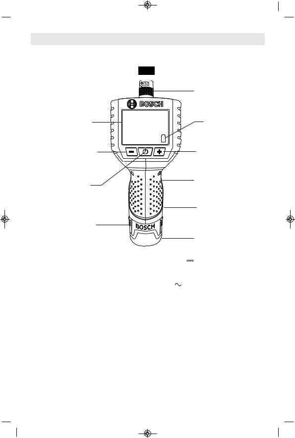
Cordless Inspection Camera
FIG. 1 |
|
|
|
|
|
|
IMAGER CABLE CONNECTOR |
VIEWING SCREEN |
|
|
ON SCREEN BATTERY |
|
|
CHARGE INDICATOR |
|
IMAGER ILLUMINATION |
|
|
IMAGER ILLUMINATION |
BRIGHTNESS DECREASE |
|
|
BRIGHTNESS INCREASE |
ON/OFF SWITCH |
|
|
VIDEO OUTPUTPORT |
|
|
(Backside of unit) |
|
|
|
|
RUBBERIZED GRIP |
BATTERY |
|
|
|
RELEASE TABS |
|
|
|
|
|
|
BATTERY PACK |
model number |
PS90 |
|
|
Voltage rating |
10.8V/12V |
MAX |
|
Battery pack |
BAT411, BAT412 & BAT413 |
||
Charger |
BC330 & BC430 |
||
Voltage rating |
120 V |
60 Hz |
|
Charge time |
BC330 (1 Hour) |
||
|
BC430 (30 minutes) |
||
Dimensions - Without Battery Pack (Nominal): |
|
|
|
Weight |
6.8 oz (0.192 kg) |
||
Length |
6.5" (166mm) |
|
|
Width |
2.6" (66mm) |
|
|
Depth |
1.8" (45mm) |
|
|
Viewing Screen: |
|
|
|
Resolution |
320 x 240 |
|
|
Screen Type |
2.7" LCD |
|
|
Operating Environment: |
|
|
|
Temperature |
-4°F to 149°F (-20°C to 65°C) |
||
Humidity |
5% to 95% non-condensing (display unit) |
||
Storage Temperature |
-22°F to 176°F (-30°C to 80°C) |
||
Video Output |
NTSC |
|
|
-5-

 BM 2610028205 10-12_BM 2610028205 10-12.qxp 10/23/12 2:13 PM Page 6
Functional Description and Specifications
FIG. 2
IMAGER HEAD |
|
|
|
LED |
|
|
|
||
|
|
|
|
|
|
|
|
|
|
 CAMERA
MIRROR
MAGNET IMAGER CABLE


HOOK

 IMAGER CABLE CONNECTOR
Optical Cable Length: 4’ (17mm diameter) included with PS90 & PS91
3’ (9.5mm diameter) included with PS91
Assembly
ImAgER CABLE ASSEmBLy
To use the Product, the imager cable must be attached to the handheld display unit. To connect the cable, make sure the key and slot are properly aligned. Once they are aligned, finger-tighten the knurled knob to hold the connector in place.
FIG. 3
SLOT |
|
|
|
KEY |
|
|
|
||
|
|
|
|
|
|
|
|
|
|
TO INSTALL AN ACCESSORy
The three included accessories, (mirror, hook and magnet) attach to the imager head in the same way. To connect, hold the imager head, slip the semicircle end of the accessory over the flats of the imager head, then rotate the accessory a 1/4 turn so the long arm of the accessory is extending out.Always direct the cord toward the rear, and away from the shear. Keep it away from sharp edges.
FIG. 4
-6-
 BM 2610028205 10-12_BM 2610028205 10-12.qxp 10/23/12 2:13 PM Page 7
Operating Instructions
PRODUCT DESCRIPTION
The Product is a hand-held optical inspection device designed to provide the user with the ability to view objects in otherwise inaccessible places. The image is displayed in full color on the viewing screen.
This device is equipped with an imaging and lighting source that features LED light adjustment allowing the user to optimize the lighting conditions for the viewing situation. These features ensure a detailed and accurate visual inspection. The mirror, hook, magnet accessories can be attached to the imager head to provide application flexibility.
USINg ThE PRODUCT
To turn the unit on, hold the viewer with the LCD screen facing you. Press the ON/OFF switch to turn on the unit. To adjust the brightness of the LED light, press the Button with the (+) sign to increase the brightness and press the Button with the (-) sign to decrease the brightness.
Gently insert the imager head and cable into the environment containing the object to be viewed. The intensity of the illumination should be adjusted to give the best image on the viewing screen. In some circumstances less is best (especially if the object is highly reflective).
The unit can be connected to an external NTSC monitor using the Video-Out connector. The connector is accessed by inserting one end of a standard 3.5mm plug to RCA video cable into the product and the other end into a monitor capable of displaying a standard NTSC video signal. After use, remove the video cable from the product.
Do not use the cable or imager head to modify surroundings, clear pathways or clogged areas, or as anything other than an inspection device.
The hand-held display unit is not water resistant. The imager head and its covering are water resistant, but are not acid-proof or fireproof. Petroleum-based products will ruin the imager head’s protective plastic covering over time. Avoid submersing the imager head into corrosive, oily places.
Do not insert the imager head and cable into any space containing live electric wiring or moving parts.
Do not use this device for medical inspections. This is not a medical device and personal injury could occur.
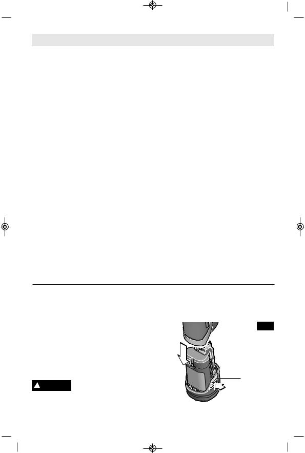
INSERTINg AND RELEASINg
BATTERy PACK
Release battery pack from tool by pressing on both sides of the battery release tabs and pull downward (Fig. 5).
To insert battery, align battery and slide battery pack into tool until it locks into position. Do not force.
If battery release tabs are ! WARNING cracked or otherwise
damaged, do not insert into tool. Battery can fall out during operation.
FIG. 5
BATTERY
RELEASE
TABS
-7-
 BM 2610028205 10-12_BM 2610028205 10-12.qxp 10/23/12 2:13 PM Page 8
ImPORTANT ChARgINg NOTES
1.The charger was designed to fast charge the battery only when the battery temperature is between 32˚F (0˚C) and 113˚F (45˚C). If the battery pack is too hot or too cold, the charger will not fast charge the battery. (This may happen if the battery pack is hot from heavy use). When the battery temperature returns to between 32˚F (0˚C) and 113˚F (45˚C), the charger will automatically begin charging.
2.A substantial drop in operating time per charge may mean that the battery pack is nearing the end of its life and should be replaced.
3.Remember to unplug charger during storage period.
4.If battery does not charge properly:
a.Check for voltage at outlet by plugging in some other electrical device.
b.Check to see if outlet is connected to a light switch which turns power “off” when lights are turned off.
c.Check battery pack terminals for dirt. Clean with cotton swab and alcohol if necessary.
d.If you still do not get proper charging, take or send tool, battery pack and charger to your local Bosch Service Center. See “Tools, Electric” in the Yellow Pages for names and addresses.
Note: Use of chargers or battery packs not sold by Bosch will void the warranty.
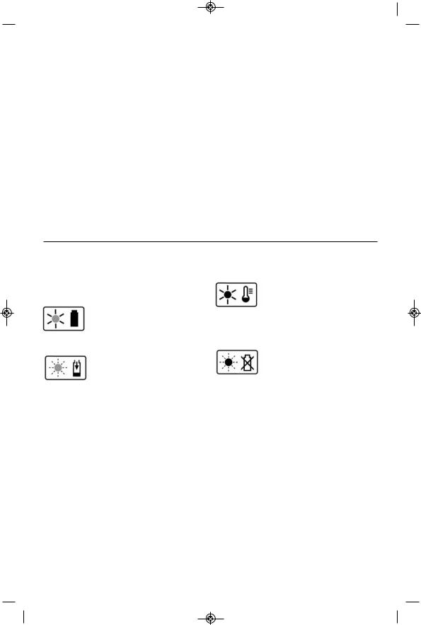
ChARgER INDICATORS, SymBOLS AND mEANINg (model BC430)
If the indicator lights are “OFF”, the charger is not receiving power from power supply outlet.
If the green indicator light is “ON”, the charger is plugged in but the battery pack is not inserted, or the battery pack is
fully charged and is being trickle charged.
If the green indicator light is “BLINKING”, the battery pack is being fast-charged. Fast-
charging will automatically stop when the battery pack is fully charged.
If the red indicator light is “ON”, the battery pack is too hot or cold for fast-charging. The
charger will switch to trickle charge, until a suitable temperature is reached, at which time the charger will switch automatically to fast-charging.
If the red indicator light is “BLINKING”, the battery pack cannot accept a charge or the
contacts of the charger or battery pack are contaminated. Clean the contacts of the charger or battery pack only as directed in these operating instructions or those supplied with your tool or battery pack.
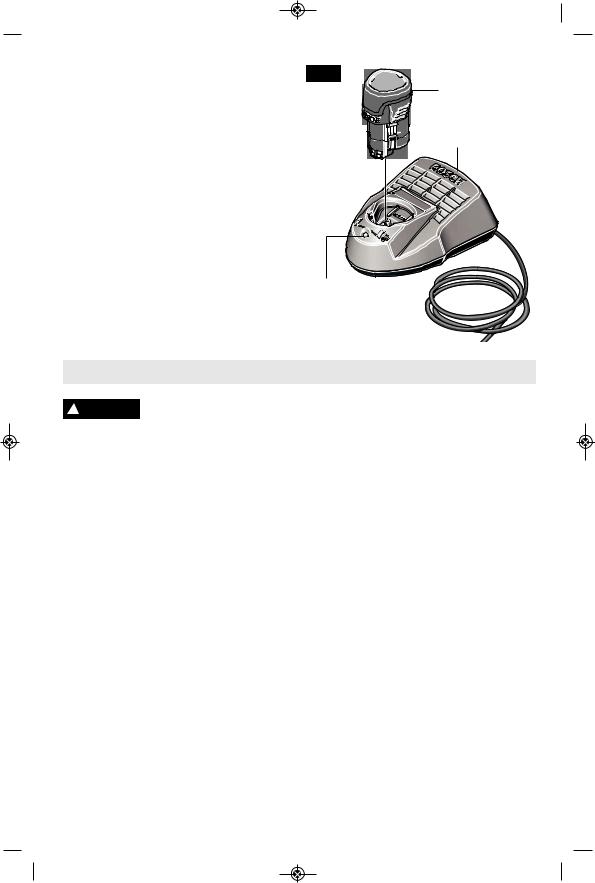
ChARgINg BATTERy PACK (model BC430)
The lithium ion battery is protected against deep discharging by the “Electronic Cell Protection (ECP)”. When the battery is empty, the tool is switched off by means of a protective circuit.
The battery is supplied partially charged. Completely charge the battery before using your cordless screwdriver for the first time. The lithium ion battery can be charged at any time, without reducing its service life.
Interrupting the charging procedure does not damage the battery.
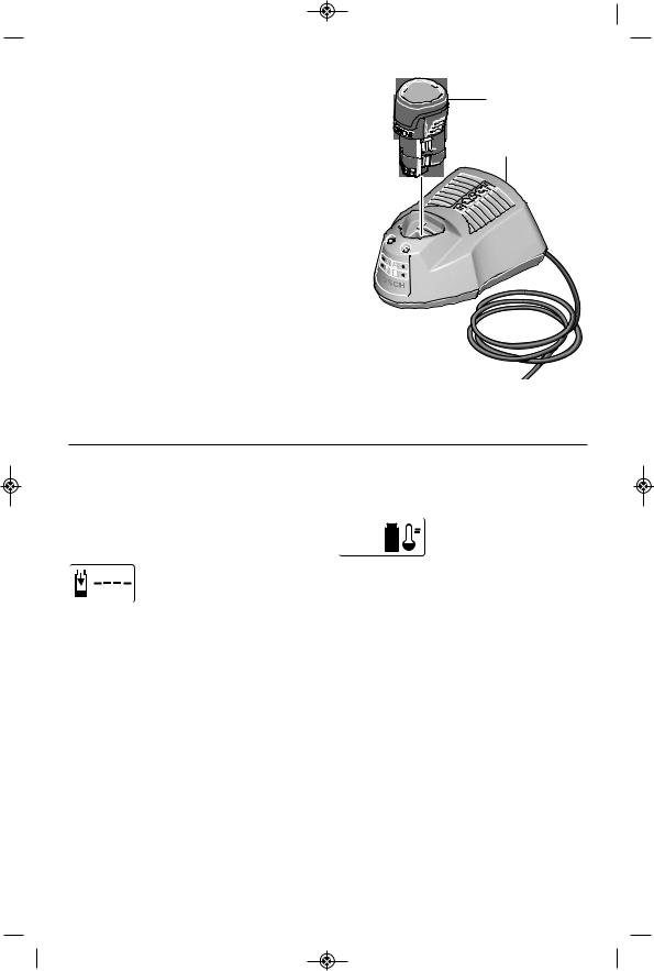
Plug charger cord into your standard power outlet, then insert battery pack into charger (Fig. 6).
The charger’s green indicator light will begin to “BLINK”. This indicates that the battery is receiving a fast charge. Fast-charging will automatically stop when the battery pack is fully charged.
-8-
 BM 2610028205 10-12_BM 2610028205 10-12.qxp 10/23/12 2:13 PM Page 9
When the indicator light stops “BLINKING” |
|
FIG. 6 |
|
|
|
|
(and becomes a steady green light) fast |
|
|
|
|
|
|
|
|
|
|
|
|
|
charging is complete. |
|
|
|
|
|
|
The battery pack may be used even though |
|
|
|
|
|
|
the light may still be blinking. The light may |
|
|
|
|
|
|
|
|
|
|
|
|
|
require more time to stop blinking depending |
|
|
|
|
|
|
|
|
|
|
|
|
|
on temperature. When you begin the |
|
|
|
|
|
|
charging process of the battery pack, a |
|
RED |
|
|
||
steady red light could also mean the battery |
|
|
|
|||
LIGHT |
|
|
||||
pack is too hot or too cold. |
|
|
||||
|
|
|
|
|
|
|
The purpose of the green light is to indicate |
|
|
|
|
|
|
that the battery pack is fast-charging. It does |
|
|
|
|
|
|
|
|
|
|
|
|
|
not indicate the exact point of full charge. |
|
|
|
|
|
|
|
|
|
|
|
|
|
The light will stop blinking in less time if the |
|
|
|
|
|
|
battery pack was not completely discharged. |
|
|
|
|
|
|
When charging several batteries in sequence, |
|
|
|
|
|
|
the charge time may slightly increase. |
GREEN |
|
|
|||
When the battery pack is fully charged, |
LIGHT |
|
|
|||
unplug the charger (unless you're charging |
|
|
|
|
|
|
another battery pack) and slip the battery |
|
|
|
|
|
|
pack back into the tool. |
|
|
|
|
|
|
BATTERY
PACK
CHARGER
ChARgER INDICATORS, SymBOLS AND mEANINg (model BC330)
If the indicator lights are “OFF”, the charger is not receiving power from power supply outlet.
If the green indicator light is “BLINKING”, the battery pack is being fast-charged. Fast-charging will
automatically stop when the battery pack is fully charged.
If the green indicator light is

 "ON", the charger is plugged in but the battery pack is not inserted, or the battery pack is
fully charged, or the battery pack is too hot or cold for fast-charging. The charger will automatically switch to fast-charging once a suitable temperature is reached.
ChARgINg BATTERy PACK (model BC330)
The lithium ion battery is protected against deep discharging by the “Electronic Cell Protection (ECP)”. When the battery is empty, the tool is switched off by means of a protective circuit.
The battery is supplied partially charged. Completely charge the battery before using your cordless screwdriver for the first time. The lithium ion battery can be charged at any time, without reducing its service life. Interrupting the charging procedure does not damage the battery.
Plug charger cord into your standard power outlet, then insert battery pack into charger (Fig. 7).
The charger’s green indicator light will begin to “BLINK”. This indicates that the battery is receiving a fast charge. Fast-charging will automatically stop when the battery pack is fully charged.
When the indicator light stops “BLINKING” (and becomes a steady green light) fast charging is complete.
-9-
 BM 2610028205 10-12_BM 2610028205 10-12.qxp 10/23/12 2:13 PM Page 10
The battery pack may be used even though the light may still be blinking. The light may require more time to stop blinking depending on temperature. When you begin the charging process of the battery pack, a steady green light could also mean the battery pack is too hot or too cold.
The purpose of the green light is to indicate that the battery pack is fast-charging. It does not indicate the exact point of full charge. The light will stop blinking in less time if the battery pack was not completely discharged.
When the battery pack is fully charged, unplug the charger (unless you're charging another battery pack) and slip the battery pack back into the tool.
FIG. 7
GREEN LIGHT
BATTERY
PACK
CHARGER
Trouble Shooting
! WARNING
PROBLEm
Read instruction manual first! Remove battery pack from the tool before making adjustments or assembling accessories.
TROUBLE: PRODUCT DOES NOT TURN ON
1.Battery pack not charged.
2.Battery pack not installed properly.
3.Battery pack temperature is too hot or cold for operation.
REmEDy 1. Charge battery if needed.
2.Confirm battery is locked and secured to the tool.
3.Let battery sit a few minutes or until it reaches normal operating temperature.
TROUBLE: PRODUCT BEhAVES ERRATICALLy
PROBLEm 1. Low Battery.
REmEDy 1. Charge battery if needed.
TROUBLE: UNIT SWITChES OFF IN USE PROBLEm 1. Battery pack not charged.
2. Battery pack temperature is too hot or cold for operation.
REmEDy 1. Charge battery if needed.
2. Let battery sit a few minutes or until it reaches normal operating temperature.
TROUBLE: PRODUCT TURNS ON BUT DOES NOT DISPLAy AN ImAgE PROBLEm 1. Imager cable not connect.
2. Imager head covered in dirt
REmEDy 1. Check cable connections. 2. Clean imager head.
-10-
 Loading...