


Installation instructions Instructions d'installation Instrucciones de instalación
Cooktop
Model:
NIT3065...
NIT5065...
NIT5665...
NIT8065...
NIT8655...

Installation instructions. . . . . . . . . .3 . -. 1. 3. . . .
Instructions d'installation. . . . . . . . .14. -. .24. . .
Instrucciones de instalación. . . . . . . .25.- . 35. .
2

Table of contents
Important Safety |
Instructions. |
. . . . . . . . . . . . . . . . |
. |
. |
. |
. |
.4 . . . . |
Before you begin. |
. . . . . |
. . . . . . . . . . . . . . . . |
. |
. |
. |
. |
. 5. . . . |
Tools and parts needed. . . . . . . . . . . . . . . . . . . . . . . . . . 5. . . . .
Parts included. . . . . |
. . . . . . . . . . . . . . |
. |
. . |
. |
. |
. .. .. . . |
. 5. . . . . |
|||
Preparation . . . . . . . |
. . . . . . . . . . . |
. |
. |
. |
. . |
. |
. |
.. .. .. .. . |
. 6. . . . . |
|
Installation procedure. |
. |
. . . . . . . . . . |
. . |
|
. |
. . |
. |
. . |
. . . . |
. 9. . . . |
Installing the heat shield. . . . . . . . . . . . . . . . . . . . . . . . . . 9. . . . .
Secure the cooktop |
to countertop. . . . . . . . . . . |
. . . . . . . . . . 10. . . . . |
|||||||
Electrical |
installation. |
. . . . . . . . . . . . . . . . |
. . . . . . . . . . 11. . . . . |
||||||
Test the installation. |
. . . . . . . . . . . . . . . . . |
. |
. . . |
. |
. . |
. . 12. . . . . . |
|||
Technical |
service. |
. . . . . . . . . . . . . . . . |
|
. |
. . . |
. |
. . |
. . 13. . . . . |
|
3
Important Safety Instructions
READ AND SAVE THESE INSTRUCTIONS
Important |
SAVE THESE |
INSTRUCTIONS FOR |
LOCAL |
INSPECTOR'S |
USE |
|
|
|
|
|
|
||||||||||||
|
|
THIS APPLIANCE MUST BE INSTALLED BY A QUALIFIED TECHNICIAN |
|
|
|
||||||||||||||||||
|
|
LEAVE THESE INSTRUCTIONS WITH THE APPLIANCE AFTER INSTALLATION IS |
|||||||||||||||||||||
|
|
COMPLETE. |
|
|
|
|
|
|
|
|
|
|
|
|
|
|
|
|
|
|
|
||
|
|
|
|
WARNING:bIf the information in this manual is not |
followed exactly, |
fire |
|||||||||||||||||
|
|
shock |
may result causing property damage or personal injury. |
|
|
|
|
||||||||||||||||
|
|
|
|
WARNING:bDo not repair or replace any part of the appliance unless |
|||||||||||||||||||
|
|
specifically |
recommended in the manual. Never modify or alter the |
|
|||||||||||||||||||
|
|
|
|
construction |
of the |
appliance. |
|
|
|
|
|
|
|
|
|
|
|
|
|
|
|||
|
|
|
|
Improper installation, technical service or maintenance can cause injury o |
|||||||||||||||||||
|
|
|
|
property damage. Refer to this manual. Consult with a factory authorized |
|||||||||||||||||||
|
|
|
|
service center for all repairs. |
|
|
|
|
|
|
|
|
|
|
|
|
|
|
|||||
|
|
Remove all tape and packaging before using |
the |
appliance. |
Destroy |
the |
packag |
||||||||||||||||
|
|
after unpacking the appliance. Never allow children to |
play |
with packaging |
mat |
||||||||||||||||||
Safe appliance handling |
Hidden |
surfaces may have sharp edges. |
Use |
caution |
when |
reaching |
behind |
or |
|||||||||||||||
|
|
under |
appliance. |
|
|
|
|
|
|
|
|
|
|
|
|
|
|
|
|
|
|
||
Electrical |
safety |
Before |
installing, turn off at the service |
|
panel. |
Lock service |
panel |
to |
prevent p |
||||||||||||||
|
|
from being turned on accidentally. |
|
|
|
|
|
|
|
|
|
|
|
|
|
|
|
||||||
|
|
The |
circuit breaker |
should |
have a |
contact |
separation |
of |
at |
least 3 mm. on all |
|||||||||||||
|
|
Be sure your appliance is properly |
installed |
and |
grounded |
by |
a qualified |
techni |
|||||||||||||||
|
|
Have the installer show you the location |
of the |
circuit breaker |
or |
fuse. |
Mark it |
||||||||||||||||
|
|
easy |
reference. |
|
|
|
|
|
|
|
|
|
|
|
|
|
|
|
|
|
|
||
|
|
This appliance has been tested in accordance with ANSI/UL 858 |
Standard |
for |
|||||||||||||||||||
|
|
Safety for Household Electric Ranges and CAN/CSA-22.2 No. 61 National |
|
||||||||||||||||||||
|
|
Standard of Canada for Household Cooking Ranges. |
It |
is |
the responsibility |
of |
|||||||||||||||||
|
|
owner and installer to determine if additional requirements and standards |
apply |
||||||||||||||||||||
|
|
specific |
installations. |
|
|
|
|
|
|
|
|
|
|
|
|
|
|
|
|
|
|||
Related |
equipment safety |
This |
stove is |
guaranteed |
safe |
for |
use |
only |
if |
it |
is installed |
by |
a |
specialist |
purs |
||||||||
|
|
the |
installation |
instructions. |
The |
installer |
is responsible |
for |
any |
damage |
caused |
||||||||||||
|
|
to improper installation. |
|
|
|
|
|
|
|
|
|
|
|
|
|
|
|
|
|
||||
|
|
To eliminate the risk of burns or fire when touching |
hot |
surface |
units, |
avoid l |
|||||||||||||||||
|
|
storage space in the cabinets over the surface units. |
In |
the event of |
presence |
||||||||||||||||||
|
|
storage in cabinets, the risk can be reduced by installing a hood that extends |
|||||||||||||||||||||
|
|
horizontally at |
least 5 inches (12.7 |
cm) |
|
from |
the |
cabinet |
bottom. |
|
|
|
|
|
|||||||||
|
|
Do not install refrigerators, dishwashers, unvented ovens, or |
washers |
that |
may f |
||||||||||||||||||
|
|
below |
the cooktop. |
|
|
|
|
|
|
|
|
|
|
|
|
|
|
|
|
|
|||
Note:bWe strongly recommend the installation of a ventilation system with this appliance.
4
Before you begin
Tools and parts needed
D Phillips head screwdriver
D Pencil
D Drill with 1/4" (6.35 mm) bit
DJigsaw
DTape measure
Note:bAdditional materials may be necessary for installation in solid surface countertops. Contact the countertop manufacturer.
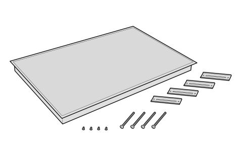
Parts included
D Hold down brackets (4)
D Clamping screws #10-32 x 2 1/2" (63.8 mm) (4) D Sheet metal screws #8 x 3/8" (9.5 mm) (4)
5
Preparation
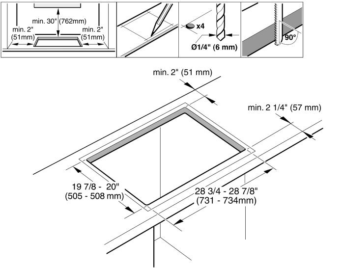
Countertop requirements |
WARNING:bTo reduce the risk |
of ignition of nearby combustible material |
||||
|
install the countertop with a minimum distance |
of 2" |
(51mm) |
from both |
||
|
walls and the back wall. |
|
|
|
|
|
Note |
The work surface should be horizontal |
and |
level. The |
stability |
of the |
countertop |
|
should be confirmed even after making |
the |
cutout. |
|
|
|
|
After preparing cutout, remove shavings as they can affect the function of elec |
|||||
|
components. |
|
|
|
|
|
|
Seal the surfaces of the cutout to make them heat |
resistant. This prevents the |
||||
|
surfaces from expanding as a result of |
humidity. |
|
|
|
|
Solid surface countertops often require special installation. For example, heat reflective tape or rounded corners may be necessary. Contact the countertop manufacturer for instructions specific to your countertop.
30" Models: NIT3065...
NIT5065...
NIT8065...
6

36" Models: NIT5665...
NIT8665...
7
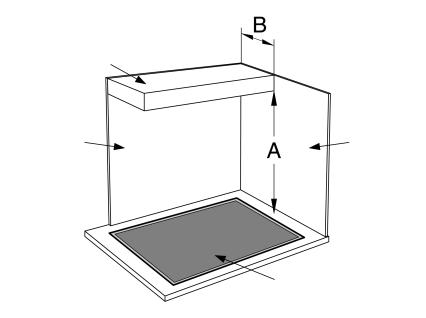
Cabinet requirements |
The |
distance |
from |
the top |
of |
the cooktop to the bottom of the cabinets abov |
|||
|
must |
be |
A |
= |
30" |
(762 |
mm) |
minimum. This distance can be reduced to |
|
|
A = |
24" |
(610 |
mm) when the |
bottom of |
the wood or metal cabinet is protect |
|||
|
less than 1/4" (6.35 mm) flame retardant |
millboard, covered by no. 28 steel s |
|||||||
|
0.015" (0.4 mm) thick stainless |
steel, 0.024" (0.6 mm) aluminum, or 0.020" (0. |
|||||||
|
thick copper, at a minimum. Verify that the cabinets above the cooktop are a |
||||||||
|
maximum |
of |
B=13" |
(330 mm) |
deep. |
|
|||
Cabinet bottom (unprotected)
Building back wall |
Building side wall |
Cooking surface
8

Installation procedure
WARNING:bUse protective gloves when installing the plate. |
|
|
|
Installing the heat shield For safety reasons, the heat shield |
must be properly installed. This |
prevents |
|
components from overheating as a result of the recirculation of hot |
air |
from th |
|
cooktop. |
|
|
|
The heat shield is the same width |
as the cooktop. For shipping, it |
is |
screwed |
burner box. |
|
|
|
After unpacking the cooktop, unscrew the heat shield (see illustration).
The heat shield will be able to rotate freely, as shown in the illustration.
9
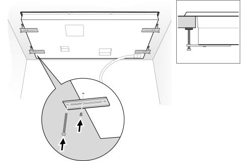
Secure the cooktop to countertop
Not to |
let |
the |
glass to |
•drop" |
into place and that it needs to be supported |
broad |
area |
of |
the edges |
when |
•placing" the cooktop into the cutout. |
The cooktop should be secured to the countertop using the clamping brackets provided.
Before |
inserting the cooktop into the cutout, turn the cooktop upside down an |
attach |
brackets to the burner box using the screws. |
Place cooktop into cutout.
Insert clamping screw into the bracket and secure cooktop to countertop. Use a wood block to protect fragile countertop materials.
10
Electrical installation
Electrical requirements |
You can |
find |
the |
identification plate with the electrical specifications on |
the |
|
underside |
of |
the |
appliance. The junction box must be located within 3 |
feet |
(~900 mm) of the cooktop connection. It should be easily accessible for servic purposes.
3 1/4º max (79 mm) + Fitting/Conduit 1º (23 mm)
12º approx. (300 mm)
Connection (ºJº) box
1º min (26 mm) air clearance
Conduit approx. 3 ft. (~900 mm)
Power supply
NIT3065, |
NIT5065 |
and |
NIT8065 models... |
||
|
40 Amp |
circuit |
breaker |
||
|
240 Volts, 3 Wire, 60 Hz |
||||
|
208 |
Volts, |
3 Wire, |
60 Hz |
|
All with 39" (1m) flexible conduit (included) |
|||||
|
|||||
|
|||||
NIT5665 and NIT8665 models... |
|||||
|
50 Amp |
circuit |
breaker |
||
|
240 Volts, 3 Wire, 60 Hz |
||||
|
208 |
Volts, |
3 Wire, |
60 Hz |
|
All |
with 39" |
(1m) |
flexible |
conduit included |
|
|
|
|
|
|
|
11
 Loading...