


HF 0 602 209
Bosch HF 0 602 209, HF 0 602 211, HF 0 602 208, HF 0 602 210, HF 0 602 226 Operating Instructions Manual
...
EURO • Printed in Germany • BA 3 609 929 765 • HF-GGS • Titel (Vorderseite) • OSW 09/00
HF-GGS - Buch Seite 1 Donnerstag, 7. September 2000 9:03 09
Bedienungsanleitung
Operating Instructions
Instructions d’emploi
Instrucciones de servicio
Manual de instruções
Istruzioni d’uso
Gebruiksaanwijzing
Betjeningsvejledning
Bruksanvisning
Brukerveiledningen
Käyttöohje
O‰ЛБ›· ¯ВИЪИЫМФ‡
Yönetmelik
HF 0 602 207 ...
HF 0 602 208 ...
HF 0 602 209 ...
HF 0 602 210 ...
HF 0 602 211 ...
HF 0 602 225 ...
HF 0 602 226 ...
HF 0 602 227 ...
HF 0 602 228 ...
HF 0 602 229 ...
HF 0 602 233 ...
HF 0 602 236 ...
HF 0 602 237 ...
HF 0 602 245 ...
Deutsch
English
Français
Español
Português
Italiano
Nederlands
Dansk
Svenska
Norsk
Suomi
EППЛУИО¿
Türkçe

EURO • Printed in Germany • BA 3 609 929 765 • HF-GGS • Titel Seite 2 • OSW 09/00
HF-GGS - Buch Seite 2 Donnerstag, 7. September 2000 9:03 09
1 614 482 048
1 607 950 001
d [mm]
0 602 207 ... 1/4" 1 608 570 058
0 602 207 ... 6,0 1 608 570 025
0 602 208 ... 1/4" 1 608 570 058
0 602 208 ... 6,0 1 608 570 025
0 602 209 ... 1/4" 1 608 570 058
0 602 209 ... 6,0 1 608 570 025
d
0 602 210 ... 1/4" 1 608 570 058
0 602 210 ... 6,0 1 608 570 025
0 602 211 004 - 018 6,0 1 608 570 043
0 602 225 ... 3,0 1 608 570 031
0 602 228 361 - 377 3,0 1 608 570 021
0 602 233 … 3,0 1 608 570 031
0 602 233 ... 6,0 1 608 570 037
0 602 236 …, 237… 3,0 1 608 570 031
3 609 929 765 • 09.00
d
d [mm]
0 602 226 ... 6,0 2 608 570 084
0 602 227 ... 6,0 2 608 570 084
0 602 228 201 - 211 6,0 2 608 570 084
0 602 229 … 6,0 2 608 570 084
EURO • Printed in Germany • BA 3 609 929 765 • HF-GGS • Titel Seite 3 • OSW 09/00
HF-GGS - Buch Seite 3 Donnerstag, 7. September 2000 9:03 09
A
3 609 929 765 • 09.00
C
4
B
5
D
3
4
3

EURO • Printed in Germany • BA 3 609 929 765 • HF/GGS • Bildseite • OSW 09/00
HF-GGS - Buch Seite 4 Donnerstag, 7. September 2000 9:03 09
2
3
4
1
a
3 609 929 765 • 09.00
d
b
c
1
1
e
1
52
12
62
3 P + ∆10 h 100 - 300 Hz > 50 V DIN 49 462/63
3 P 4 h 100 - 200 Hz ≤ 50 V
L1
L2
L3
1
EURO•BA 3 609 929 765•HF/GGS 2 207-245•OSW 09/00•Titel Umschlagseite 5
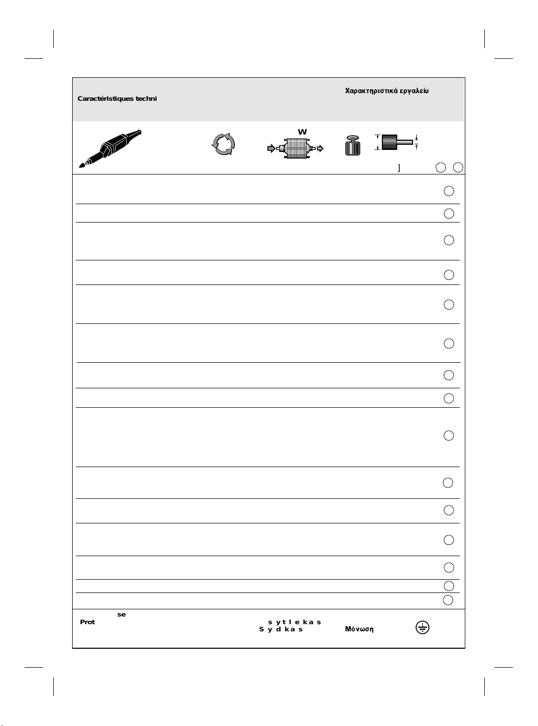
Gerätekennwerte Dati tecnici Tekniset tiedot
Tool Specifications Technische gegevens
Caractéristiques techniques Tekniske data Teknik veriler
Caracteristicas técnicas Tekniska data
Dados técnicos do aparelho Tekniske data
[W]
P
Г·Ъ·ОЩЛЪИЫЩИО¿ ВЪБ·ПВ›˘
a
FIU
[Hz] [mm]
0 602 207 001 265 200 23 400 600 440 1,6 2,4 max. 32 6
0 602 207 004 135 200 23 400 600 440 3,3 2,4 max. 32 6
0 602 207 008 72 200 23 400 600 440 5,9 2,4 max. 32 6
0 602 208 001 135 200 18 300 600 440 3,3 2,4 max. 50 6
0 602 208 001 200 300 27 400 900 630 3,3 2,4 max. 27 6
0 602 209 101 265 200 12 000 600 440 1,6 2,5 max. 50 6
0 602 209 104 135 200 12 000 600 440 3,3 2,5 max. 50 6
0 602 209 107 72 200 12 000 600 440 5,9 2,5 max. 50 6
0 602 209 111 72 300 18 000 900 630 8,8 2,5 max. 50 6
0 602 209 134 200 300 18 000 900 630 3,3 2,5 max. 50 6
0 602 210 001 265 200 3 100 600 440 1,6 2,5 max. 50 6
0 602 210 004 135 200 3 100 600 440 3,3 2,5 max. 50 6
0 602 210 004 200 300 4 700 900 630 3,3 2,5 max. 50 6
0 602 211 004 265 200 12 000 950 700 2,8 4,3 max. 50 8
0 602 211 010 135 200 12 000 950 700 5,5 4,3 max. 50 8
0 602 211 010 200 300 18 000 1450 1050 5,5 4,3 max. 50 8
0 602 211 017 72 200 12 000 950 700 10,0 4,3 max. 50 8
0 602 211 018 72 200 18 000 1450 1050 15,2 4,3 max. 50 8
0 602 225 101 265 200 50 000 80 40 0,2 0,6 max. 8 3
0 602 225 104 135 200 50 000 80 40 0,5 0,6 max. 8 3
0 602 225 107 72 200 50 000 80 40 0,9 0,6 max. 8 3
0 602 225 204 200 300 50 000 125 65 0,5 0,6 max. 8 3
0 602 225 211 72 300 50 000 125 65 1,4 0,6 max. 8 3
0 602 226 201 265 200 30 500 260 150 0,9 1,6 max. 25 6
0 602 226 204 135 200 30 500 260 150 1,7 1,6 max. 25 6
0 602 226 207 72 200 30 500 260 150 3,2 1,6 max. 25 6
0 602 227 211 72 300 29 000 400 230 4,6 1,6 max. 25 6
0 602 227 204 200 300 29 000 400 230 1,7 1,6 max. 25 6
0 602 228 201 265 200 12 000 260 150 0,9 1,6 max. 50 6
0 602 228 204 135 200 12 000 260 150 1,7 1,6 max. 50 6
0 602 228 204 200 300 18 000 400 230 1,7 1,6 max. 50 6
0 602 228 207 72 200 12 000 260 150 3,2 1,6 max. 50 6
0 602 228 211 72 300 18 000 400 230 4,6 1,6 max. 50 6
0 602 228 361 265 200 12 000 260 150 0,9 1,6 max. 50 6
0 602 228 364 135 200 12 000 260 150 1,7 1,6 max. 50 6
0 602 228 364 200 300 18 000 400 230 1,7 1,6 max. 50 6
0 602 228 371 265 200 12 000 260 150 0,9 1,6 max. 50 6
0 602 228 374 135 200 12 000 260 150 1,7 1,6 max. 50 6
0 602 228 374 200 300 18 000 400 230 1,7 2,4 max. 40 6
0 602 228 377 72 200 12 000 260 150 3,2 1,6 max. 50 6
0 602 229 101 265 200 12 000 260 150 0,9 1,3 max. 50 6
0 602 229 104 135 200 12 000 260 150 1,7 1,3 max. 50 6
0 602 229 104 200 300 18 000 400 230 1,7 1,3 max. 50 6
0 602 233 201 265 200 50 000 260 150 0,9 1,6 max. 8 3
0 602 233 204 135 200 50 000 260 150 1,7 1,6 max. 8 3
0 602 233 207 72 200 50 000 260 150 3,2 1,6 max. 8 3
0 602 233 304 200 300 50 000 400 230 1,7 1,6 max. 8 3
0 602 236 001 265 200 50 000 170 85 0,5 1,0 max. 8 3
0 602 236 004 135 200 50 000 170 85 1,0 1,0 max. 8 3
0 602 236 007 72 200 50 000 170 85 1,8 1,0 max. 8 3
0 602 237 004 200 300 50 000 265 135 1,0 1,0 max. 8 3
0 602 245 011 72 300 18 000 1800 1500 17,7 4,7 max. 40 M14
0 602 245 034 200 300 18 000 1800 1500 6,4 4,7 max. 40 M14
Schutzklasse
Protection class
Classe de protection
Clase de protección
Classe de protecção
Classe di protezione
Isolatieklasse
[min-1] [kg]
Beskyttelsesklasse
Skyddsklass
Beskyttelsesklasse
[A][V] [W] [mm]
[W] −
Suojausluokka
ªfiÓˆÛË
Koruma s∂n∂f∂
b
ba
œ
ON/OFF
Typ
a
a
a
a
a
a
d
b
b
b
e
b
b
d
d
c
/ I
e
09/00
•
3 609 929 765

1
2
3
4
5
.
■
■
■
■
■
■
■
■
■
■
EURO • Printed in Germany • BA 3 609 929 765 • HF/GGS • D • OSW 09/00
HF-GGS - Buch Seite 1 Donnerstag, 7. September 2000 9:03 09
Geräteelemente
Ein-/Ausschalter
Spindelhals
Schleifspindel
Spannzange
Spannmutter
Abgebildetes oder beschriebenes Zubehör gehört
teilweise nicht zum Lieferumfang.
Bestimmungsgemäßer Gebrauch
Das Gerät ist bestimmt zum Schleifen und Entgraten von Metall mit Korundschleifkörpern.
Geräusch-/Vibrationsinformation
Messwerte ermittelt entsprechend EN 50 144.
Der A-bewertete Schalldruckpegel des Gerätes
beträgt typischerweise
Der Geräuschpegel beim Arbeiten kann
85 dB (A) überschreiten.
Gehörschutz tragen!
Die bewertete Beschleunigung beträgt typischerweise
Typ
2 207 78 < 2,5
2 208 81 < 2,5
2 209 101, …111 77 < 2,5
2 209 134 77 7,0
2 210 001…004 (200 Hz) 72 < 2,5
2 210 004 (300 Hz) 81 < 2,5
2 211 76 < 2,5
2 211 010 (200 Hz) 79 < 2,5
2 211 010 (300 Hz) 79 3,5
2 225 < 70 3,0
2 226 < 70 4,0
2 227 70 3,0
2 228 201, …202, …207, …211 71 3,0
2 228 204 (300 Hz) 71 4,5
2 228 204 (200 Hz) 71 < 2,5
2 228 361…377 71 5,0
2 229 73 3,0
2 233 < 70 3,0
2 236 < 70 3,0
2 237 72 3,0
2 245 79 < 2,5
(B) m/s
2
(A) dB (A).
(A) (B)
Zu Ihrer Sicherheit
Gefahrloses Arbeiten mit dem
Gerät ist nur möglich, wenn Sie
die Bedienungsanleitung und die
Sicherheitshinweise vollständig
lesen und die darin enthaltenen
Anweisungen strikt befolgen. Zusätzlich müssen die allgemeinen
Sicherheitshinweise im beigelegten Heft befolgt werden. Lassen
Sie sich vor dem ersten Gebrauch praktisch einweisen.
Wird bei der Arbeit das Netzkabel
beschädigt oder durchtrennt, Kabel
nicht berühren, sondern sofort den
Netzstecker ziehen. Gerät niemals
mit beschädigtem Kabel benutzen.
Schutzbrille und Gehörschutz tragen.
Wenn notwendig, auch Schürze tragen.
Schutzhandschuhe und festes
Schuhwerk tragen.
Beim Arbeiten das Gerät immer fest
mit beiden Händen halten und für
einen sicheren Stand sorgen.
Niemals Kindern die Benutzung des Gerätes
gestatten.
Stecker nur bei ausgeschaltetem Gerät in die
Steckdose einstecken.
Kabel immer nach hinten vom Gerät wegführen.
Werkstück einspannen, sofern es nicht durch
sein Eigengewicht sicher liegt.
Asbesthaltiges Material darf nicht bearbeitet
werden.
Nur Schleifwerkzeuge verwenden, deren zulässige Drehzahl mindestens so hoch ist wie
die Leerlaufdrehzahl des Gerätes.
Anweisung des Herstellers zur Montage und
Verwendung des Schleifwerkzeuges beachten.
Schleifwerkzeug vor Schlag, Stoß und Fett
schützen.
Hände weg von rotierenden Schleifwerkzeugen.
Gerät nicht im Schraubstock festspannen.
3 609 929 765 • TMS • 16.08.00
Deutsch - 1
œ
■
■
■
■
■
■
■
EURO • Printed in Germany • BA 3 609 929 765 • HF/GGS • D • OSW 09/00
HF-GGS - Buch Seite 2 Donnerstag, 7. September 2000 9:03 09
■
■
■
■
3
4
4
Das Gerät nur eingeschaltet gegen das Werkstück führen.
Die Drehrichtung beachten. Gerät immer so
halten, dass Funken oder Schleifstaub vom
Körper weg fliegen.
Beim Schleifen von Metallen entsteht Funkenflug. Darauf achten, dass keine Personen gefährdet werden. Wegen der Brandgefahr dürfen sich keine brennbaren Materialien in der
Nähe (Funkenflugbereich) befinden.
Gerät vor dem Ablegen immer ausschalten
und auslaufen lassen.
Vorsicht! Schleifkörper läuft nach dem Ausschalten des Gerätes noch nach.
Bosch kann nur dann eine einwandfreie Funktion des Gerätes zusichern, wenn für dieses
Gerät vorgesehenes Original-Zubehör verwendet wird.
Elektrischer Anschluss
Spannung und Frequenz der Stromquelle
müssen mit den Angaben auf dem Typschild des Gerätes übereinstimmen.
Bei extremen Einsatzbedingungen kann
sich bei der Bearbeitung von Metallen leitfähiger Staub im Innern des Gerätes absetzen. Die Schutzisolierung des Gerätes kann
beeinträchtigt werden. Es empfiehlt sich in
solchen Fällen die Verwendung einer stationären Absauganlage, häufiges Ausblasen
3 609 929 765 • TMS • 16.08.00
der Lüftungsschlitze und das Vorschalten
eines Fehlerstrom-Schutzschalters (FI).
Das Gerät darf nur an ein ordnungsgemäß
geerdetes Stromnetz angeschlossen werden. Steckdose und Verlängerungskabel
müssen einen funktionsfähigen Schutzleiter besitzen.
Steckermontage
Zum Betrieb der HF-Elektrowerkzeuge ist ein Frequenzumformer erforderlich, der Drehstrom mit
einer Frequenz von 200 bzw. 300 Hz erzeugt.
Frequenzumformer gibt es in verschiedenen Größen, mit unterschiedlichen Frequenzen, Sekundärspannungen und Nennleistungen. Die Auswahl des Umformers ist abhängig von den anzuschließenden Geräten.
Das Gerät wird mit einem vier Meter langen Sonderkabel ohne Stecker geliefert.
Es wird ein 4-poliger CEE-Stecker (16 A belastbar) mit der Kennfarbe grün benötigt. Die Schutzkontaktbuchse muss sich in der 10 h-Stellung befinden.
Die Steckermontage ist vom Fachmann gemäß
Bild vorzunehmen. Die Kontakte sind entsprechend DIN 49 462/63 angeordnet.
Adern-Kennzeichnung
L1 (R1) braun
L2 (S2) blau
L3 (T3) schwarz
PE (
) grün-gelb
Drehrichtung feststellen
Die Drehrichtung des Werkzeugs muss mit dem
Pfeil auf dem Gerätekopf übereinstimmen. Dreht
sich das Werkzeug bei der ersten Inbetriebnahme
falsch herum, müssen zwei Phasen im Stecker
miteinander getauscht werden.
Bei falscher Drehrichtung löst sich das
Werkzeug von der Schleifspindel.
Schleifwerkzeuge montieren
(Zubehör)
Vor allen Arbeiten am Gerät Netzstecker
ziehen.
Nur Schleifwerkzeuge verwenden, deren
zulässige Drehzahl mindestens so hoch ist
wie die Leerlaufdrehzahl des Gerätes.
Zu montierende Teile reinigen. Schleifspin-
☞
A B
Schlüssel lösen.
Spannschaft des Schleifkörpers bis zum An-
schlag in die Spannzange stecken.
Spannzange
Typ 0 602 245 ...
C
Gabelschlüssel SW 17 festhalten. Schleifkörper
aufschrauben und festziehen.
Das Innengegewinde des Schleifkörpers muss
tiefer sein, als die Länge der Schleifspindel. Die
Schleifspindel darf nicht am Grund der Schleifkörperbohrung aufsitzen.
an der Schlüsselfläche mit Gabel-
del
schlüssel SW 17 festhalten.
Spannzange
Schleifspindel 3 an der Schlüsselfläche mit
bzw. Spannmutter 5 mit
bzw. Spannmutter 5 festziehen.
Deutsch - 2
EURO • Printed in Germany • BA 3 609 929 765 • HF/GGS • D • OSW 09/00
HF-GGS - Buch Seite 3 Donnerstag, 7. September 2000 9:03 09
3
4
3
4
4
■
■
Typ 0 602 228 361, ...364, ...371, ...374, ...377:
D
Zum Lösen der Spannzange 4 die Schleifspindel
gehäuse der Schlitz des Exzenterbolzens sichtbar wird. Die Klinge des Winkelschraubendrehers
in den Schlitz des Exzenterbolzens stecken und
so drehen, dass die Spannzange
Schleifspindel
Spannschaft des Schleifkörpers bis zum Anschlag in die Spannzange stecken.
Zum Spannen des Schleifkörpers den Winkelschraubendreher so drehen, dass die Spannzange
wird. Festsitz des Schleifkörpers überprüfen.
Lässt sich der Schleifkörper nicht festspannen,
mit dem Winkelschrauberdreher die Exzenterspannung lösen, die Spannzange
bzw. herausschrauben und den Schleifkörper mit
dem Winkelschrauberdreher wieder festspannen.
drehen, bis in der Bohrung im Spindel-
aus der
herausgedrückt wird.
in die Schleifspindel 3 hineingezogen
etwas hinein-
Inbetriebnahme
Spannung und Frequenz der Stromquelle müssen mit den Angaben auf dem Typschild des Gerätes übereinstimmen.
Probelauf!
☞
Schleifwerkzeuge vor Gebrauch überprüfen. Das Schleifwerkzeug muss einwandfrei montiert sein und sich frei drehen können. Probelauf mindestens 30 Sekunden
ohne Belastung durchführen. Beschädigte,
unrunde oder vibrierende Schleifwerkzeuge nicht verwenden.
Arbeitshinweise
Schutzbrille tragen.
Optimale Schleifergebnisse werden erreicht,
wenn der Schleifkörper mit leichtem Druck gleichmäßig hin- und herbewegt wird.
Zu starker Druck verringert die Leistungsfähigkeit
des Gerätes und der Schleifkörper verschleißt
schneller.
Unrunde Schleifkörper nicht weiter verwenden:
Mit Abziehstein (Zubehör) richten oder auswechseln.
Wartung und Reinigung
Vor allen Arbeiten am Gerät Netzstecker
ziehen.
Gerät und Lüftungsschlitze stets sauber
☞
halten, um gut und sicher zu arbeiten.
Sollte das Gerät trotz sorgfältiger Herstellungsund Prüfverfahren einmal ausfallen, ist die Reparatur von einer autorisierten Kundendienststelle
für Bosch-Elektrowerkzeuge ausführen zu lassen.
Bei allen Rückfragen und Ersatzteilbestellungen
bitte unbedingt die 10-stellige Bestellnummer laut
Typenschild des Gerätes angeben.
3 609 929 765 • TMS • 16.08.00
Deutsch - 3
EURO • Printed in Germany • BA 3 609 929 765 • HF/GGS • D • OSW 09/00
HF-GGS - Buch Seite 4 Donnerstag, 7. September 2000 9:03 09
Garantie
Für Bosch-Geräte leisten wir Garantie gemäß
den gesetzlichen/länderspezifischen Bestimmungen (Nachweis durch Rechnung oder Lieferschein).
Schäden, die auf natürliche Abnützung, Überlastung oder unsachgemäße Behandlung zurückzuführen sind, bleiben von der Garantie ausgeschlossen.
Beanstandungen können nur anerkannt werden,
wenn Sie das Gerät
unzerlegt an den Lieferer
oder an eine Bosch-Kundendienstwerkstätte für
Druckluft- oder Elektrowerkzeuge senden.
Umweltschutz
Rohstoffrückgewinnung statt Müllentsorgung
Gerät, Zubehör und Verpackung sollten einer umweltgerechten Wiederverwertung zugeführt werden.
Diese Anleitung ist aus chlorfrei gefertigtem Recycling-Papier hergestellt.
Zum sortenreinen Recycling sind Kunststoffteile
3 609 929 765 • TMS • 16.08.00
gekennzeichnet.
In Deutschland sind nicht mehr gebrauchsfähige
Geräte zum Recycling beim Handel abzugeben
oder (ausreichend frankiert) direkt einzuschicken
an:
Recyclingzentrum Elektrowerkzeuge
Osteroder Landstraße 3
37589 Kalefeld
Industriewerkzeug-Partner
Deutschland
Robert Bosch GmbH
Servicezentrum Elektrowerkzeuge
Zur Luhne 2
D-37589 Kalefeld-Willershausen
..........................................
Service
✆
Fax
...........................................................
Kundenberater:........................ 01 80 - 3 33 57 99
✆
01 80 - 3 35 54 99
0 55 53 - 20 22 37
Österreich
ABE Service GmbH
Jochen-Rindt-Straße 1
A-1232 Wien
✆ Service.............................................. (02 22) 61 03 80
........................................................ (02 22) 61 03 84 91
Fax
✆ Kundenberater:................. (02 22) 7 97 22 30 20
Schweiz
Kammermann Elektrowerkzeuge
Ziegelfeldstrasse 23 - 25
CH-4603 Olten
✆ .................................................................. 0 62 - 32 17 77
......................................................................0 62 32 56 34
Fax
Konformitätserklärung
Wir erklären in alleiniger Verantwortung, dass
dieses Produkt mit den folgenden Normen oder
normativen Dokumenten übereinstimmt:
EN 50 144, HD 400 gemäß den Bestimmungen
der Richtlinien 89/336/EWG, 98/37/EG.
Dr. Gerhard Felten Dr. Eckerhard Strötgen
Robert Bosch GmbH, Geschäftsbereich Elektrowerkzeuge
Änderungen vorbehalten
Deutsch - 4
EURO • Printed in Germany • BA 3 609 929 765 • HF/GGS • GB • OSW 09/00
HF-GGS - Buch Seite 1 Donnerstag, 7. September 2000 9:03 09
Machine Elements
1 On/Off switch
2 Spindle collar
3 Grinder spindle
4 Collet chuck
5 Clamping nut
Not all of the accessories illustrated or described are
included as standard delivery.
Intended Use
The machine is intended for grinding and deburring of metal with corundum grinding tools.
Noise/Vibration Information
Measured values determined according to
EN 50 144.
The A-weighted sound pressure level of the tool
is typically (A) dB (A).
The noise level when working can exceed
85 dB (A).
Wear ear protection!
The weighted acceleration is typically (B) m/s
Type (A) (B)
2 207 78 < 2.5
2 208 81 < 2.5
2 209 101, …111 77 < 2.5
2 209 134 77 7.0
2 210 001…004 (200 Hz) 72 < 2.5
2 210 004 (300 Hz) 81 < 2.5
2 211 76 < 2.5
2 211 010 (200 Hz) 79 < 2.5
2 211 010 (300 Hz) 79 3.5
2 225 < 70 3.0
2 226 < 70 4.0
2 227 70 3.0
2 228 201, …202, …207, …211 71 3.0
2 228 204 (300 Hz) 71 4.5
2 228 204 (200 Hz) 71 < 2.5
2 228 361…377 71 5.0
2 229 73 3.0
2 233 < 70 3.0
2 236 < 70 3.0
2 237 72 3.0
2 245 79 < 2.5
2
.
For Your Safety
Working safely with this machine
is possible only when the operating and safety information are
read completely and the instructions contained therein are
strictly followed. In addition, the
general safety instructions in the
enclosed booklet must be followed. Before using for the first
time, ask for a practical demonstration.
If the mains cable is damaged or cut
through while working, do not touch
the cable but immediately pull the
mains plug. Never use the machine
with a damaged cable.
Wear protective glasses and ear
protection.
When necessary, also wear an
apron.
Wear protective gloves and sturdy
shoes.
When working with the machine, always hold it firmly with both hands
and provide for a secure stance.
■ Never allow children to use the machine.
■ Insert the mains plug only when the machine is
switched off.
■ Always direct the cable to the rear away from
the machine.
■ Clamp the workpiece if it does not remain stationary due to its own weight.
■ Do not work with materials containing asbestos.
■ Use only grinding tools with a permissible
speed at least as high as the no-load speed of
the machine.
■ Observe the manufacturer’s instructions for
mounting and using grinding tools.
■ Protect the grinding tool from impact, shock
and grease.
■ Keep hands away from rotating grinding tools.
■ Do not clamp the machine in a vice.
■ Apply the machine to the workpiece only when
switched on.
3 609 929 765 • TMS • 16.08.00
English - 1
EURO • Printed in Germany • BA 3 609 929 765 • HF/GGS • GB • OSW 09/00
HF-GGS - Buch Seite 2 Donnerstag, 7. September 2000 9:03 09
■ Pay attention to the direction of rotation. Always hold the machine so that sparks and
grinding dust fly away from the body.
■ When grinding metal, flying sparks are produced. Take care that no persons are endangered. Due to danger of fire, no combustible
materials should be located in the vicinity
(spark flight zone).
■ Always switch off the machine and allow to
come to a stop before placing it down.
■ Caution! The grinding tool runs on after the machine is switched off.
■ Bosch is only able to ensure perfect functioning
of the machine if the original accessories intended for it are used.
Electrical Connection
■ The voltage and frequency of the power
source must agree with those given on the
nameplate of the machine.
■ In extreme working conditions, conductive
dust can accumulate in the interior of the
machine when working with metal. The protective insulation of the machine can be degraded. The use of a stationary extraction
system is recommended in such cases as
well as frequently blowing out the ventilation slots and installing a residual current
device (RCD).
3 609 929 765 • TMS • 16.08.00
■ The machine may be connected only to
properly earthed mains. The socket and extension cable must have a functional protective conductor.
Attaching the Plug
For operating the HF power tools, a frequency
converter is required that generates three-phase
current with a frequency of 200 or 300 Hz.
Frequency converters are available in various
sizes with different frequencies, secondary voltages and power ratings. The selection of the converter is dependent on the machine to be connected.
The machine is delivered with a special, four metre long cable without plug.
A four-pole CEE plug (16 A capacity) with the
identifying colour of green is necessary. The protective contact socket must be in the 10 o’clock
position.
The plug must be mounted by a qualified electrician according to the illustration. The contacts are
arranged according to DIN 49 462/63.
Conductor Identification
L1 (R1) brown
L2 (S2) blue
L3 (T3) black
PE ( œ) green-yellow
Determine the Direction of Rotation
The rotational direction of the tool must agree with
the arrow on the machine head. If the tool rotates
in the wrong direction when first put into operation, two phases in the plug must be interchanged.
For the wrong direction of rotation, the
tool will loosen itself from the grinder
spindle.
Mounting the Grinding Tools
(Optional Accessories)
■ Before any work on the machine itself, pull
the mains plug.
■ Use only grinding tools with a permissible
speed at least as high as the no-load speed
of the machine.
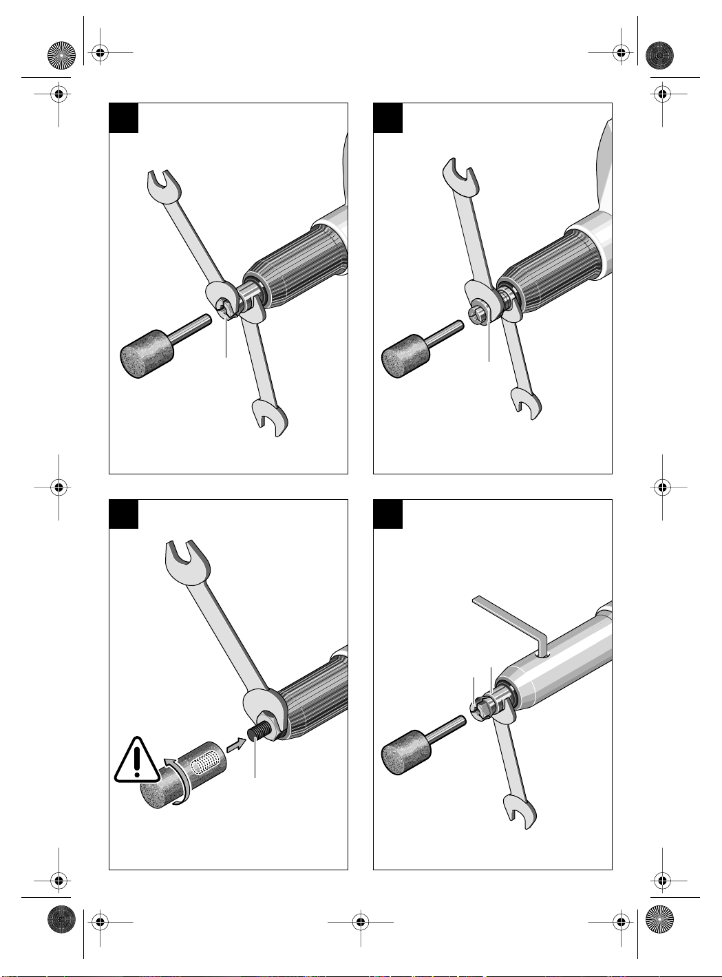
Clean the parts to be mounted. Hold the
☞
grinder spindle 3 on the spanner surfaces
with a 17 mm open-ended spanner.
A B
Loosen the collet chuck 4 or the clamping
nut 5 with a spanner.
Insert the clamping shaft of the grinding tool to the
stop into the collet chuck.
Tighten the collet chuck 4 or the clamping nut 5.
Type 0 602 245 ...
C
Hold the grinding spindle 3 across the flats
using an open-end wrench, size 17 mm. Screw
on grinding accessory and tighten.
The female thread of the grinding tool must be
deeper than the length of the grinding spindle.
The grinding spindle must not run against the bottom of the grinding accessory hole.
English - 2
EURO • Printed in Germany • BA 3 609 929 765 • HF/GGS • GB • OSW 09/00
HF-GGS - Buch Seite 3 Donnerstag, 7. September 2000 9:03 09
Type 0 602 228 361, ...364, ...371, ...374, ...377:
D
To loosen the collet 4, turn the grinding spindle 3 until the slot of the eccentric bolt is visible in
the hole of the spindle housing. Insert the blade of
the offset screwdriver into the slot of the eccentric
bolt and turn in such a manner, that the collet 4 is
pressed out of the grinding spindle 3.
Insert the clamping shaft of the grinding tool to the
stop into the collet chuck.
To clamp the grinding accessory, turn the offset
screwdriver in such a manner, that the collet 4 is
pulled into the grinding spindle 3. Check for tight
seating of the grinding tool bit.
If the grinding accessory can not be clamped
tight, loosen the eccentric tension with the offset
screwdriver, screw the collet 4 somewhat in or out
and retighten the grinding accessory with the offset screwdriver again.
Initial Operation
The voltage and frequency of the power source
must agree with those given on the nameplate of
the machine.
Test run!
☞
Check the grinding tool before use. The
grinding tool must be flawlessly mounted
and be able to rotate freely. Perform a test
run of at least 30 seconds without load. Do
not use damaged, out-of-round or vibrating
grinding tools.
Maintenance and Cleaning
■ Before any work on the machine itself, pull
the mains plug.
For safe and proper working, always keep
☞
the machine and the ventilation slots clean.
If the machine should fail despite the rigorous
manufacturing and testing procedures, repair
should be carried out by an authorised after-sales
service centre for Bosch power tools.
In all correspondence and spare parts orders,
please always include the 10-digit order number
given on the nameplate of the machine.
Guarantee
We guarantee Bosch appliances in accordance
with statutory/country-specific regulations (proof
of purchase by invoice or delivery note).
Damage attributable to normal wear and tear,
overload or improper handling will be excluded
from the guarantee.
In case of complaint please send the machine,
undismantled, to your dealer or the Bosch Service Centre for electric power tools.
Environmental Protection
3 609 929 765 • TMS • 16.08.00
Operating Instructions
■ Wear safety goggles.
Optimum grinding results are achieved when the
grinding tool is moved uniformly back and forth
with light pressure.
Pressure that is too strong reduces the performance capability of the machine and causes the
grinding tool to wear more quickly.
Do not continue to use out-of-round grinding
tools. Dress with a dressing stone (optional accessory) or replace.
English - 3
Recycle raw materials instead of disposing as
waste.
The machine, accessories and packaging should
be sorted for environmental-friendly recycling.
These instructions are printed on recycled paper
manufactured without chlorine.
The plastic components are labelled for categorized recycling.
EURO • Printed in Germany • BA 3 609 929 765 • HF/GGS • GB • OSW 09/00
HF-GGS - Buch Seite 4 Donnerstag, 7. September 2000 9:03 09
Industrial Tool Partner
Great Britain
CC Tools
29 Clophill Road
Maulden
Bedford MK452AA
✆ ............................................................... 15 25 - 84 07 55
............................................................... 15 25 - 84 07 72
Fax
Terratruck
34, 36 Gipsy Lane
Leicester LE4 6RB
✆ .............................................................. 1 16 - 2 66 24 56
...................................................... 1 16 - 5 33 61 03 04
Fax
Rewinds & Windsor
81 Regent Road
Liverpool L59SY
✆ .............................................................. 1 51 - 2 07 20 74
.............................................................. 1 51 - 2 98 14 42
Fax
Air Tools Northern
Millshaw Park Tr. Est.
Elland Road
Leeds LS 11 02X
✆ .............................................................. 1 13 - 2 71 44 20
.............................................................. 1 13 - 2 71 69 04
Fax
Price Tool Sales
50 Summer Lane
3 609 929 765 • TMS • 16.08.00
Birmingham B193TL
✆ .............................................................. 1 21 - 3 59 88 91
.............................................................. 1 21 - 3 59 16 21
Fax
Ireland
Beaver Distribution Ltd.
Greenhills Road
IRL-Tallaght-Dublin 24
✆ ................................................................. (01) 4 51 52 11
................................................................. (01) 4 51 71 27
Fax
USA
Power Tool Service
3718 Polk Avenue
Houston, TX 77003
✆ ........................................................... 7 13 - 2 28 - 01 00
........................................................... 7 13 - 2 28 - 06 19
Fax
Subject to change without notice
Declaration of Conformity
We declare under our sole responsibility that this
product is in conformity with the following standards or standardisation documents: EN 50 144,
HD 400 according to the provisions of the directives 89/336/EEC, 98/37/EC.
Dr. Gerhard Felten Dr. Eckerhard Strötgen
Robert Bosch GmbH, Geschäftsbereich Elektrowerkzeuge
English - 4
EURO • Printed in Germany • BA 3 609 929 765 • HF/GGS • F • OSW 09/00
HF-GGS - Buch Seite 1 Donnerstag, 7. September 2000 9:03 09
Eléments de la machine
1 Interrupteur Marche/Arrêt
2 Collet de broche
3 Broche porte-outil
4 Pince de serrage
5 Ecrou de serrage
Les accessoires reproduits ou décrits ne sont pas
forcément fournis avec la machine.
Utilisation conformément à la
destination de l’appareil
L’appareil est conçu pour les travaux de ponçage
et d’ébarbage des pièces métalliques avec des
abrasifs de corindon.
Bruits et vibrations
Valeurs de mesure obtenues conformément à la
norme européenne 50 144.
La mesure réelle (A) du niveau sonore de l'outil
est de (A) dB (A).
Le niveau sonore en fonctionnement peut dépasser 85 dB (A).
Munissez-vous d’une protection acoustique !
L’accélération réelle mesurée est de (B) m/s
Type (A) (B)
2 207 78 < 2,5
2 208 81 < 2,5
2 209 101, …111 77 < 2,5
2 209 134 77 7,0
2 210 001…004 (200 Hz) 72 < 2,5
2 210 004 (300 Hz) 81 < 2,5
2 211 76 < 2,5
2 211 010 (200 Hz) 79 < 2,5
2 211 010 (300 Hz) 79 3,5
2 225 < 70 3,0
2 226 < 70 4,0
2 227 70 3,0
2 228 201, …202, …207, …211 71 3,0
2 228 204 (300 Hz) 71 4,5
2 228 204 (200 Hz) 71 < 2,5
2 228 361…377 71 5,0
2 229 73 3,0
2 233 < 70 3,0
2 236 < 70 3,0
2 237 72 3,0
2 245 79 < 2,5
2
.
Pour votre sécurité
Pour travailler sans risque avec
cet appareil, lire intégralement au
préalable les instructions d’utilisation et les remarques concernant la sécurité. Respecter scrupuleusement les indications et
les consignes qui y sont données. En plus, il convient de respecter les consignes d’ordre général touchant à la sécurité qui
sont définies dans le cahier cijoint. Avant la première mise en
service, laisser quelqu’un connaissant bien cet appareil vous
indiquer la façon de s’en servir.
Si le câble d’alimentation électrique
est endommagé ou se rompt pendant le travail, ne pas y toucher. Retirer immédiatement la fiche du câble d’alimentation de la prise de
courant. Ne jamais utiliser un appareil dont le cordon d’alimentation est
endommagé.
Porter des lunettes de sécurité et
une protection acoustique.
Si nécessaire, porter également un
tablier.
Porter des gants de protection et
des chaussures solides à semelles
antidérapantes.
Pendant le travail avec cet appareil,
le tenir toujours fermement avec les
deux mains. Adopter une position
stable et sûre.
■ Ne jamais permettre aux enfants d’utiliser cet
appareil.
■ Ne brancher l’appareil que si celui-ci est en position « Arrêt ».
■ Toujours ramener les câbles à l’arrière de l’appareil.
■ Serrer la pièce au cas où elle ne serait pas assez lourde et risquerait de bouger.
■ Ne jamais travailler de matériau contenant de
l’amiante.
■ N’utiliser que des outils de ponçage dont la vitesse admissible est au moins égale à la vitesse de rotation en marche à vide de l’appareil.
3 609 929 765 • TMS • 16.08.00
Français - 1

EURO • Printed in Germany • BA 3 609 929 765 • HF/GGS • F • OSW 09/00
HF-GGS - Buch Seite 2 Donnerstag, 7. September 2000 9:03 09
■ Respecter les instructions du fabricant concernant le montage et l’emploi des outils de ponçage.
■ Protéger les outils de ponçage des chocs mécaniques et de tout les contact avec un corps
gras.
■ Eviter tout contact avec des outils de ponçage
en rotation.
■ Ne pas fixer l’appareil dans un étau.
■ N’appliquer l’appareil contre la pièce à usiner
que lorsque celui-ci est en marche.
■ Observer le sens de rotation de l’outil. Tenir
l’appareil de telle sorte que les étincelles ou la
poussière de meulage soient projetées dans la
direction opposée à celle du corps.
■ La rectification des métaux génère des étincelles. Veiller à ce que personne ne soit exposé à
un danger. En raison du risque d’incendie,
aucune matière inflammable ou combustible
ne doit se trouver dans la zone de projection
des étincelles.
■ Toujours déconnecter l’appareil et le laisser ralentir jusqu’à l’arrêt avant de le déposer.
■ Attention ! Par inertie, les outils de ponçage
continuent de tourner quelques instants après
l’arrêt de l’appareil.
■ Bosch ne peut garantir un fonctionnement impeccable que si les accessoires Bosch d’origine prévus pour cet appareil sont utilisés.
3 609 929 765 • TMS • 16.08.00
Raccordement électrique
■ Tension et fréquence de la source de courant doivent correspondre aux indications
figurant sur la plaque signalétique de la machine.
■ Dans certaines conditions d’exploitation
délicates, pendant l’usinage de métaux, de
la poussière conductrice d’électricité peut
se déposer à l’intérieur de l’appareil et ainsi
en altérer l’isolation de protection. Si tel est
le cas, Bosch recommande l’emploi d’un
dispositif d’aspiration stationnaire, de
souffler fréquemment dans les ouïes de refroidissement et de monter en amont un
disjoncteur différentiel.
■ L’appareil ne doit être branché que sur un
réseau de courant électrique correctement
relié à la terre. La prise de courant ainsi que
la rallonge électrique doivent être munies
d’un conducteur de protection en bon état.
Montage de la fiche
Pour le service des outils électroportatifs HF, un
variateur de fréquence est nécessaire qui produit
un courant triphasé d’une fréquence de 200 ou
300 Hz.
Il existe des variateurs de fréquence de différentes dimensions, avec fréquences, tensions secondaires et puissances nominales différentes.
Le choix du variateur dépend des appareils qu’on
désire brancher dessus.
L’appareil est fourni avec un câble spécial d’une
longueur de quatre mètres sans fiche.
Il faut une fiche CEE avec 4 pôles (16 A admissible) de couleur caractéristique verte. La douille de
contact de mise à terre doit être en position 10 h.
Le montage de la fiche doit être effectué par un
spécialiste conformément à la figure. Les contacts sont disposés conformément à la norme
DIN 49 462/63.
Identification des conducteurs
L1 (R1) brun
L2 (S2) bleu
L3 (T3) noir
PE ( œ) vert-jaune
Détermination du sens de rotation
Le sens de rotation de l’outil doit coïncider avec la
flèche se trouvant sur la tête de l’appareil. Au cas
où l’outil tournerait dans le mauvais sens de rotation lors de sa mise en fonctionnement initiale,
échanger deux conducteurs dans la fiche.
En cas de mauvais sens de rotation,
l’outil se détache de la broche de ponçage.
Montage des outils de ponçage
(accessoires)
■ Avant toute intervention sur l’appareil pro-
prement dit, toujours retirer la fiche du câble d’alimentation de la prise de courant.
■ N’utiliser que des outils de ponçage dont la
vitesse admissible est au moins égale à la
vitesse de rotation en marche à vide de l’appareil.
Nettoyer les pièces à monter. Maintenir la
☞
broche de ponçage 3 sur la face à clé à
l’aide d’une clé à fourche (taille d’ouverture 17).
Français - 2
EURO • Printed in Germany • BA 3 609 929 765 • HF/GGS • F • OSW 09/00
HF-GGS - Buch Seite 3 Donnerstag, 7. September 2000 9:03 09
A B
Desserrer la pince de serrage 4 ou l’écrou
de serrage 5 à l’aide de la clé.
Introduire à fond la tige de la meule dans la pince
de serrage.
Serrer la pince de serrage 4 ou l’écrou de ser-
rage 5.
Type 0 602 245 ...
C
Maintenir la broche de ponçage 3 sur la face
à clé à l’aide d’une clé à fourche (taille d’ouverture 17). Visser l’outil de ponçage et le serrer.
La longueur du filetage intérieur de l’outil de ponçage doit dépasser celle de la broche de ponçage. La broche de ponçage ne doit pas reposer
sur le fond de l’alésage de l’outil de ponçage.
Type 0 602 228 361, ...364, ...371, ...374, ...377:
D
Afin de desserrer la pince de serrage 4, tourner la broche de ponçage 3 jusqu’à ce que la
fente du boulon excentrique soit visible dans l’alésage se trouvant dans le logement de la broche.
Introduire la lame du tournevis angulaire dans la
fente du boulon excentrique et tourner de sorte à
pouvoir extraire à l’aide d’une pression la pince
de serrage 4 de la broche de ponçage 3.
Introduire à fond la tige de la meule dans la pince
de serrage.
Pour serrer l’outil de ponçage, tourner le tournevis angulaire de sorte que la pince de serrage 4
soit insérée dans la broche de ponçage 3. Contrôler que l’outil de ponçage soit bien fixé.
Au cas où l’outil de ponçage ne pourrait pas être
serré, détendre la tension excentrique à l’aide du
tournevis angulaire, visser ou dévisser légèrement la pince de serrage 4 et resserrer l’outil à
l’aide du tournevis angulaire de ponçage.
Mise en service
Tension et fréquence de la source de courant doivent correspondre aux indications figurant sur la
plaque signalétique de la machine.
Essai de marche !
☞
Contrôler les outils de ponçage avant de les
utiliser. L’outil doit être correctement monté
et doit pouvoir tourner librement. Effectuer
un essai de marche en laissant tourner
l’outil sans sollicitation pendant au moins
30 secondes. Ne pas utiliser d’outils de
ponçage endommagées, déséquilibrées ou
générant des vibrations.
Instructions d’utilisation
■ Porter des lunettes de protection.
Vous obtiendrez des résultats de travail optimaux
en guidant l’appareil de façon régulière et en
exerçant une pression modérée.
Une pression trop importante réduit la performance de l’appareil et l’outil de ponçage s’use
plus vite.
Ne plus continuer à utiliser des outils de ponçage
qui ne sont pas ronds: les ajuster à l’aide d’une
pierre à aiguiser (accessoire) ou les échanger.
Nettoyage et entretien
■ Avant toute intervention sur l’appareil pro-
prement dit, toujours retirer la fiche du câble d’alimentation de la prise de courant.
Pour obtenir un travail sûr et satisfaisant,
☞
nettoyer régulièrement l’appareil ainsi que
ses ouïes de refroidissement.
Si, malgré tous les soins apportés à la fabrication
et au contrôle de l’appareil, celui-ci devait avoir un
défaut, la réparation ne doit être confiée qu’à une
station de service après-vente agréée pour
outillage Bosch.
Pour toute demande de renseignements ou commande de pièces de rechange, nous préciser impérativement le numéro de référence à dix chiffres de la machine.
Garantie
Les appareils Bosch sont garantis conformément
aux dispositions légales/nationales (contre
preuve d’achat, facture ou bordereau de livraison). Cette garantie implique le remplacement
gratuit des pièces défectueuses. En tout état de
cause s’applique la garantie légale couvrant toutes les conséquences des défauts ou vices cachés. (Articles 1641 et suivants du Code civil.)
Cette garantie correspond à un emploi normal de
l’outil et exclut les avaries dues à un mauvais
usage, à un entretien défectueux ou à l’usure normale. Le jeu de la garantie ne peut en aucun cas
donner lieu à des dommages et intérêts.
Pour que cette garantie soit valable, il y a lieu de
retourner l’outil non démonté au vendeur ou à
une station de service après-vente Bosch, accompagné de la preuve d’achat mentionnant la
date d’acquisition, le nom de l’utilisateur et le nom
du revendeur.
3 609 929 765 • TMS • 16.08.00
Français - 3
EURO • Printed in Germany • BA 3 609 929 765 • HF/GGS • F • OSW 09/00
HF-GGS - Buch Seite 4 Donnerstag, 7. September 2000 9:03 09
Instructions de protection de
l’environnement
Récupération des matières premières plutôt
qu’élimination des déchets
Les machines, comme d’ailleurs leurs accessoires et emballages, doivent pouvoir suivre chacune une voie de recyclage appropriée.
Ce manuel d’instructions a été fabriqué à partir
d’un papier recyclé blanchi en l’absence de
chlore.
Nos pièces plastiques ont ainsi été marquées en
vue d’un recyclage sélectif des différents matériaux.
Partenaire en outillages
industriels
France
Outils Pneumatiques Globe
143, Av. du General de Gaulle
BP 102
F-92252 La Garenne Colombes
✆ .................................................................. 1 - 47 80 20 81
.................................................................. 1 - 47 80 29 13
Fax
Belgique
CEMAC TECHNAIR
Afrikanlaan 289 A
B-9000 Gent
✆ .................................................................. (09) 2 59 02 62
.................................................................. (09) 2 59 17 87
Fax
Suisse
Kammermann Elektrowerkzeuge
Ziegelfeldstrasse 23-25
CH-4603 Olten
✆ .................................................................. 0 62 - 32 17 77
......................................................................0 62 32 56 34
Fax
3 609 929 765 • TMS • 16.08.00
Déclaration de conformité
Nous déclarons sous notre propre responsabilité
que ce produit est en conformité avec les normes
ou documents normalisés suivants : EN 50 144,
HD 400 conformément aux réglementations
89/336/CEE, 98/37/CE.
Dr. Gerhard Felten Dr. Eckerhard Strötgen
Robert Bosch GmbH, Geschäftsbereich Elektrowerkzeuge
Sous réserve de modifications
Français - 4
EURO • Printed in Germany • BA 3 609 929 765 • HF/GGS • E • OSW 09/00
HF-GGS - Buch Seite 1 Donnerstag, 7. September 2000 9:03 09
Elementos de la máquina
1 Interruptor de conexión/desconexión
2 Cuello del husillo
3 Husillo portamuelas
4 Pinza de fijación
5 Tuerca de fijación
¡Los accesorios descritos e ilustrados no corresponden
en parte al material que se adjunta!
Utilización reglamentaria
El aparato ha sido proyectado para amolar y desbarbar metal con muelas de corindón.
Información sobre ruidos y
vibraciones
Determinación de los valores de medición según
norma EN 50 144.
El nivel de presión de sonido, típico, medido con
un filtro tipo A, es normalmente de (A) dB (A).
El nivel de ruido, con la máquina trabajando, podrá sobrepasar circunstancialmente 85 dB (A).
¡Usar protectores auditivos!
La aceleración se eleva normalmente a (B) m/s
Tipo (A) (B)
2 207 78 < 2,5
2 208 81 < 2,5
2 209 101, …111 77 < 2,5
2 209 134 77 7,0
2 210 001…004 (200 Hz) 72 < 2,5
2 210 004 (300 Hz) 81 < 2,5
2 211 76 < 2,5
2 211 010 (200 Hz) 79 < 2,5
2 211 010 (300 Hz) 79 3,5
2 225 < 70 3,0
2 226 < 70 4,0
2 227 70 3,0
2 228 201, …202, …207, …211 71 3,0
2 228 204 (300 Hz) 71 4,5
2 228 204 (200 Hz) 71 < 2,5
2 228 361…377 71 5,0
2 229 73 3,0
2 233 < 70 3,0
2 236 < 70 3,0
2 237 72 3,0
2 245 79 < 2,5
Para su seguridad
Solamente puede trabajar sin peligro con el aparato si lee íntegramente las instrucciones de manejo y las indicaciones de seguridad, ateniéndose estrictamente a
las recomendaciones allí comprendidas. Adicionalmente debe
atenerse a las indicaciones de
seguridad generales contenidas
en el folleto adjunto. Déjese instruir prácticamente en el manejo
antes de la primera aplicación.
Si llega a dañarse o cortarse el cable de red durante el trabajo, no tocar el cable, sino extraer inmediatamente el enchufe de la red. No usar
jamás el aparato con un cable deteriorado.
Llevar gafas de protección y protectores auditivos.
Si fuese preciso, ponerse además
un mandil.
Llevar guantes de protección y calzado fuerte.
2
.
■ Jamás permita que los niños utilicen el aparato.
■ Conectar la máquina a la red únicamente estando desconectada.
■ Mantener el cable siempre detrás del aparato.
■ Sujetar la pieza de trabajo, a no ser que quede
bien firme por su propio peso.
■ No deben trabajarse materiales que contengan amianto.
■ Emplear solamente útiles de amolar cuyas revoluciones admisibles sean como mínimo
iguales a las revoluciones en vacío del aparato.
■ Atenerse a las instrucciones del fabricante al
montar y aplicar el útil de amolar.
■ Proteger el útil de amolar de los golpes, choques y de la grasa.
■ Mantenga alejadas sus manos de los útiles de
amolar en funcionamiento.
Trabajar siempre con el aparato sujetándolo firmemente con ambas
manos y manteniendo una posición
estable.
3 609 929 765 • TMS • 16.08.00
Español - 1
 Loading...