


OBJ_BUCH-485-002.book Page 1 Wednesday, November 26, 2008 12:24 PM
Robert Bosch GmbH
Power Tools Division
70745 Leinfelden-Echterdingen
Germany
www.bosch-pt.com
1 609 929 S53 (2008.11) T / 200 UNI
GHG 660 LCD Professional
|
|
|
|
|
|
de |
Originalbetriebsanleitung |
el |
Πρωτότυπο οδηγιών χρήσης |
sr |
Originalno uputstvo za rad |
en |
Original instructions |
tr |
Orijinal işletme talimat |
sl |
Izvirna navodila |
fr |
Notice originale |
pl |
Instrukcją oryginalną |
hr |
Originalne upute za rad |
es |
Manual original |
cs |
Původní návod k používání |
et |
Algupärane kasutusjuhend |
pt |
Manual original |
sk |
Pôvodný návod na použitie |
lv |
Instrukcijas oriģinālvalodā |
it |
Istruzioni originali |
hu |
Eredeti használati utasítás |
lt |
Originali instrukcija |
nl |
Oorspronkelijke |
ru |
Оригинальное руководст- |
|
|
|
gebruiksaanwijzing |
|
во по эксплуатации |
|
|
da Original brugsanvisning |
uk Оригінальна інструкція з |
|
|
||
sv |
Bruksanvisning i original |
|
експлуатації |
|
|
no |
Original driftsinstruks |
ro |
Instrucţiuni originale |
|
|
fi |
Alkuperäiset ohjeet |
bg |
Оригинална инструкция |
|
|

OBJ_BUCH-485-002.book Page 2 Wednesday, November 26, 2008 11:54 AM
2 |
Deutsch . . . . . . . . . . . . . . . . . . . . . . . . |
. . . . Seite |
7 |
English . . . . . . . . . . . . . . . . . . . . . . . . . . |
. . . Page |
14 |
Français . . . . . . . . . . . . . . . . . . . . . . . . . |
. . . Page |
21 |
Español. . . . . . . . . . . . . . . . . . . . . . . . . . |
. .Página |
29 |
Português . . . . . . . . . . . . . . . . . . . . . . . . |
. .Página |
37 |
Italiano . . . . . . . . . . . . . . . . . . . . . . . . . . |
. .Pagina |
45 |
Nederlands . . . . . . . . . . . . . . . . . . . . . . . |
. .Pagina |
53 |
Dansk . . . . . . . . . . . . . . . . . . . . . . . . . . . |
. . . Side |
60 |
Svenska . . . . . . . . . . . . . . . . . . . . . . . . . |
. . . Sida |
66 |
Norsk . . . . . . . . . . . . . . . . . . . . . . . . . . . |
. . . Side |
72 |
Suomi . . . . . . . . . . . . . . . . . . . . . . . . . . . |
. . . .Sivu |
78 |
Ελληνικά . . . . . . . . . . . . . . . . . . . . . . . . . |
. . Σελίδα |
84 |
Türkçe . . . . . . . . . . . . . . . . . . . . . . . . . . |
. . . Sayfa |
92 |
Polski . . . . . . . . . . . . . . . . . . . . . . . . . . . |
. .Strona |
99 |
Česky . . . . . . . . . . . . . . . . . . . . . . . . . . . |
. . Strana |
107 |
Slovensky . . . . . . . . . . . . . . . . . . . . . . . . |
. . Strana |
113 |
Magyar . . . . . . . . . . . . . . . . . . . . . . . . . . |
. . . Oldal |
120 |
Русский . . . . . . . . . . . . . . . . . . . . . . . . |
Страница |
128 |
Українська . . . . . . . . . . . . . . . . . . . . . . . |
Сторінка |
136 |
Română . . . . . . . . . . . . . . . . . . . . . . . . . |
. . Pagina |
143 |
Български . . . . . . . . . . . . . . . . . . . . . . |
Страница |
151 |
Srpski . . . . . . . . . . . . . . . . . . . . . . . . . . . |
. . Strana |
159 |
Slovensko . . . . . . . . . . . . . . . . . . . . . . . . |
. . . Stran |
165 |
Hrvatski . . . . . . . . . . . . . . . . . . . . . . . . . |
Stranica |
172 |
Eesti . . . . . . . . . . . . . . . . . . . . . . . . . . . . |
Lehekülg |
179 |
Latviešu . . . . . . . . . . . . . . . . . . . . . . . . . |
Lappuse |
185 |
Lietuviškai . . . . . . . . . . . . . . . . . . . . . . . |
Puslapis |
193 |
|
1 609 929 S53 | (26.11.08) |
|
|
Bosch Power Tools |
|
|
||
|
|
|
|
|
|
|
|
|
|
|
|
|
|
|
|
|
|
|
|
|
|
|
|
|
|
|

OBJ_BUCH-485-002.book Page 3 Wednesday, November 26, 2008 11:54 AM
3 |
 450
450 
 ˚C
˚C
11
75 mm 1 609 390 451
50 mm 1 609 201 795
A
 450
450
 ˚C
˚C
12
75 mm 1 609 390 452
50 mm 1 609 201 796
B
13
|
HDPE |
300 ˚C |
|
|
PVC (hard) |
300 ˚C |
|
|
|
||
|
PVC (soft) |
400 ˚C |
|
|
|
||
|
PP |
260 ˚C |
|
|
|||
|
LDPE |
250 ˚C |
|
|
ABS |
350 ˚C |
|
C |
|
|
32 mm 1 609 390 453 |
|
|
|
|
|
|
|
|
14 |
HDPE |
1 609 201 807 |
HDPE |
300 ˚C |
PVC (hard) 1 609 201 808 |
||
PVC (hard) |
300 ˚C |
|
PVC (soft) 1 609 201 809 |
|
PVC (soft) |
400 ˚C |
|
PP |
1 609 201 810 |
PP |
260 ˚C |
|
LDPE |
1 609 201 811 |
LDPE |
250 ˚C |
|
|
|
|
|
15 |
16 |
1 609 201 797 |
|
|
|
||
|
|
|
|
|
D |
|
|
|
1 609 201 798 |
|
|
|
|
|
1 609 929 S53 | (26.11.08) |
|
|
Bosch Power Tools |
|
OBJ_BUCH-485-002.book Page 4 Wednesday, November 26, 2008 11:54 AM |
||
4 | |
|
|
300 ˚C |
|
|
|
|
Ø 9 mm 1 609 201 797 |
|
16 |
Ø 14 mm 1 609 201 647 |
|
Ø 20 mm 1 609 201 648 |
|
|
|
Ø 2,4–4,8 mm 1 609 201 812 |
|
17 |
Ø 4,8–9,5 mm 1 609 201 813 |
E |
|
32 mm 1 609 390 453 |
FE |
550 ˚C |
|
PVC (hard) |
300 ˚C |
|
|
18 |
80 mm 1 609 201 751 |
F |
|
|
550 ˚C |
|
16 |
|
|
Ø 9 mm 1 609 201 797 |
|
|
Ø 14 mm 1 609 201 647 |
|
|
Ø 20 mm 1 609 201 648 |
|
|
80 mm 1 609 201 751 |
G |
|
32 mm 1 609 390 453 |
1 609 929 S53 | (26.11.08) |
Bosch Power Tools |
|
OBJ_BUCH-485-002.book Page 5 Wednesday, November 26, 2008 11:54 AM |
|
5 | |
|
|
2 |
|
1 |
|
6 |
2 |
7 |
8 |
|
1 |
10 |
|
|
|
9 |
|
3 |
|
1 |
5 |
2 |
4 |
|
|
3 |
|
1 |
1 609 929 S53 | (26.11.08) |
Bosch Power Tools |

OBJ_BUCH-485-002.book Page 6 Wednesday, November 26, 2008 11:54 AM
6 |
|
|
|
|
|
|
|
|
|
|
|
|
|
|
|
|
|
|
|
|
|
|
|
|
|
|
|
|
|
|
|
|
|
|
|
|
|
|
|
|
|
|
|
|
|
|
|
|
|
|
|
|
|
|
|
|
|
|
|
|
|
|
|
|
|
|
|
|
|
|
|
|
|
|
|
|
|
|
|
|
|
|
|
|
|
|
|
|
|
|
|
|
|
|
|
|
|
|
|
|
|
|
|
|
|
|
|
|
|
|
|
|
|
|
|
|
|
|
|
|
|
|
|
|
|
|
|
|
|
|
|
|
|
|
|
|
|
|
|
|
|
|
|
|
|
|
|
|
|
|
|
|
|
|
|
|
|
|
|
|
|
|
|
|
|
|
|
|
|
|
|
|
|
|
|
|
|
|
|
|
|
|
|
|
|
|
|
|
|
|
|
|
|
|
|
|
|
|
|
|
|
|
|
|
|
|
|
|
|
|
|
|
|
|
|
|
|
|
|
|
|
|
|
|
|
|
|
|
|
|
|
|
|
|
|
|
|
|
|
|
|
|
|
|
|
|
|
|
|
|
|
|
|
|
|
|
|
|
|
|
|
|
|
|
|
|
|
|
|
|
|
|
|
|
|
|
|
|
|
|
|
|
|
|
|
|
|
|
|
|
|
|
|
|
|
|
|
|
|
|
|
|
|
|
|
|
|
|
|
|
|
|
|
|
|
|
|
|
|
|
|
|
|
|
|
|
|
|
|
|
|
|
|
|
|
|
|
|
|
|
|
|
|
|
|
|
|
|
|
|
|
|
|
|
|
|
|
|
|
|
|
|
|
|
|
|
|
|
|
|
|
|
|
|
|
|
|
|
|
|
|
|
|
|
|
|
|
|
|
|
|
|
|
1 609 929 S53 | (26.11.08) |
|
|
|
|
|
|
|
|
|
Bosch Power Tools |
|
|
|
|||||||||
|
|
|
|
|
|
|
|
|
|
|
|
|
|
|
|
|
|
|
|
|
|
|
|
|
|
|
|
|
|
|
|
|
|
|
|
|
|
|
|
|
|
|
|
|
|
|
|
|
|
|
|
|
|
|
|
|
|
|
|
|
|
|
|
|
|
|
|
|
|
|
|
|
|
|
|
|
|

OBJ_BUCH-485-002.book Page 7 Wednesday, November 26, 2008 11:54 AM
Sicherheitshinweise
Lesen Sie alle Sicherheitshinweise und Anweisungen. Versäumnisse bei der Einhaltung der Sicherheitshinweise und Anweisungen können elektrischen Schlag, Brand und/oder schwere Verletzungen verursachen.
fGehen Sie sorgsam mit dem Elektrowerkzeug um. Das Elektrowerkzeug erzeugt starke Hitze, die zu erhöhter Brandund Explosionsgefahr führt.
fSeien Sie besonders vorsichtig, wenn Sie in der Nähe brennbarer Materialien arbeiten.
Der heiße Luftstrom bzw. die heiße Düse können Staub oder Gase entzünden.
fArbeiten Sie mit dem Elektrowerkzeug nicht in explosionsgefährdeter Umgebung.
fRichten Sie den heißen Luftstrom nicht für längere Zeit auf ein und dieselbe Stelle.
Leicht entzündliche Gase können z.B. bei der Bearbeitung von Kunststoffen, Farben, Lacken oder ähnlichen Materialien entstehen.
fBeachten Sie, dass Wärme zu verdeckten brennbaren Materialien geleitet werden und diese entzünden kann.
fLegen Sie das Elektrowerkzeug nach Gebrauch sicher ab und lassen Sie es vollständig auskühlen, bevor Sie es wegpacken.
Die heiße Düse kann Schaden anrichten.
fLassen Sie das eingeschaltete Elektrowerkzeug nicht unbeaufsichtigt.
fBewahren Sie unbenutzte Elektrowerkzeuge außerhalb der Reichweite von Kindern auf. Lassen Sie Personen das Elektrowerkzeug nicht benutzen, die mit diesem nicht vertraut sind oder diese Anweisungen nicht gelesen haben. Elektrowerkzeuge sind gefährlich, wenn sie von unerfahrenen Personen benutzt werden.
fHalten Sie das Elektrowerkzeug von Regen oder Nässe fern. Das Eindringen von Wasser in ein Elektrowerkzeug erhöht das Risiko eines elektrischen Schlages.
Deutsch | 7
fZweckentfremden Sie das Kabel nicht, um das Elektrowerkzeug zu tragen, aufzuhängen oder um den Stecker aus der Steckdose zu ziehen. Halten Sie das Kabel fern von Hitze, Öl, scharfen Kanten oder sich bewegenden Geräteteilen. Beschädigte oder verwickelte Kabel erhöhen das Risiko eines elektrischen Schlages.
fTragen Sie immer eine Schutzbrille. Eine Schutzbrille verringert das Risiko von Verletzungen.
fZiehen Sie den Stecker aus der Steckdose, bevor Sie Geräteeinstellungen vornehmen, Zubehörteile wechseln oder das Elektrowerkzeug weglegen. Diese Vorsichtsmaßnahme verhindert den unbeabsichtigten Start des Elektrowerkzeuges.
fÜberprüfen Sie vor jeder Benutzung Elektrowerkzeug, Kabel und Stecker. Benutzen Sie das Elektrowerkzeug nicht, sofern Sie Schäden feststellen. Öffnen Sie das Elektrowerkzeug nicht selbst und lassen Sie es nur von qualifiziertem Fachpersonal und nur mit Original-Ersatzteilen reparieren.
Beschädigte Elektrowerkzeuge, Kabel und Stecker erhöhen das Risiko eines elektrischen Schlages.
Belüften Sie Ihren Arbeitsplatz gut. Beim Arbeiten entstehende Gase und Dämpfe sind häufig gesundheitsschädlich.
fTragen Sie Schutzhandschuhe und berühren Sie die heiße Düse nicht. Es besteht Verbrennungsgefahr.
fRichten Sie den heißen Luftstrom nicht auf Personen oder Tiere.
fVerwenden Sie das Elektrowerkzeug nicht als Haartrockner. Der austretende Luftstrom ist wesentlich heißer als bei einem Haartrockner.
fWenn der Betrieb des Elektrowerkzeugs in feuchter Umgebung nicht vermeidbar ist, verwenden Sie einen Fehlerstromschutzschalter. Der Einsatz eines Fehlerstromschutzschalters vermindert das Risiko eines elektrischen Schlages.
|
|
Bosch Power Tools |
|
|
1 609 929 S53 | (26.11.08) |
|
|
||
|
|
|
|
|
|
|
|
|
|
|
|
|
|
|
|
|
|
|
|
|
|
|
|
|
|
|
|
|
|
OBJ_BUCH-485-002.book Page 8 Wednesday, November 26, 2008 11:54 AM
8 | Deutsch
Funktionsbeschreibung
Bitte klappen Sie die Aufklappseite mit der Darstellung des Elektrowerkzeugs auf, und lassen Sie diese Seite aufgeklappt, während Sie die Betriebsanleitung lesen.
Geräuschinformation
Messwerte ermittelt entsprechend EN 60745.
Der A-bewertete Schalldruckpegel des Elektrowerkzeugs ist typischerweise kleiner als
70 dB(A).
Bestimmungsgemäßer Gebrauch
Das Elektrowerkzeug ist bestimmt zum Verformen und Verschweißen von Kunststoff, Entfernen von Farbanstrichen und zum Erwärmen von Schrumpfschläuchen. Es ist auch geeignet zum Löten und Verzinnen, Lösen von Klebeverbindungen und zum Auftauen von Wasserleitungen.
Benutzen Sie das Elektrowerkzeug nur, wenn Sie alle Funktionen voll einschätzen und ohne Einschränkungen durchführen können oder entsprechende Anweisungen erhalten haben.
Konformitätserklärung
Wir erklären in alleiniger Verantwortung, dass das unter „Technische Daten“ beschriebene Produkt mit den folgenden Normen oder normativen Dokumenten übereinstimmt: EN 60335 gemäß den Bestimmungen der Richtlinien 2006/95/EG, 2004/108/EG.
03 |
|
Dr. Egbert Schneider |
Dr. Eckerhard Strötgen |
Senior Vice President |
Head of Product |
Engineering |
Certification |
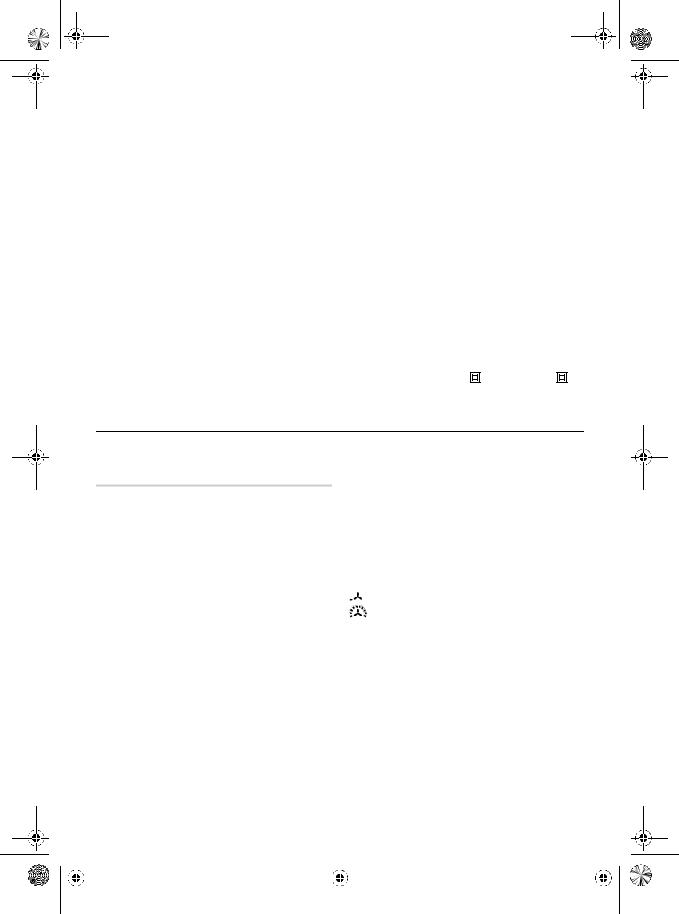
Abgebildete Komponenten
Die Nummerierung der abgebildeten Komponenten bezieht sich auf die Darstellung des Elektrowerkzeuges auf der Grafikseite.
1Ablagefläche
2Abdeckung mit Grobschmutzfilter
3Ein-/Ausschalter mit Stufenwahl
4Düse
5Wärmeschutz
6Programmwahltaste
7Display
8Taste für Luftmengenregulierung
9Taste für Temperaturregulierung
10Speichertaste
11Flächendüse*
12Glasschutzdüse*
13Reflektordüse*
14Schweißdraht*
15Schweißschuh*
16Reduzierdüse*
17Schrumpfschlauch*
18Winkeldüse*
*Abgebildetes oder beschriebenes Zubehör gehört nicht zum Standard-Lieferumfang. Das vollständige Zubehör finden Sie in unserem Zubehörprogramm.
Robert Bosch GmbH, Power Tools Division
D-70745 Leinfelden-Echterdingen
Leinfelden, 05.10.2007
|
|
1 609 929 S53 | (26.11.08) |
|
|
Bosch Power Tools |
|
|
||
|
|
|
|
|
|
|
|
|
|
|
|
|
|
|
|
|
|
|
|
|
|
|
|
|
|
|
|
|
|
OBJ_BUCH-485-002.book Page 9 Wednesday, November 26, 2008 11:54 AM
|
|
|
Deutsch | 9 |
|
|
|
|
Technische Daten |
|
|
|
|
|
|
|
Heißluftgebläse |
|
GHG 660 LCD |
GHG 660 LCD |
|
|
Professional |
Professional |
Sachnummer |
|
0 601 944 7.. |
0 601 944 7.. |
Nennspannung |
V |
220–240 |
110–120 |
Nennaufnahmeleistung |
W |
2300 |
1400 |
Luftmenge |
l/min |
250–500 |
250–500 |
Temperatur am Düsenausgang ca. |
°C |
50–660 |
50–600 |
Temperatur-Messgenauigkeit |
|
±5 % |
±5 % |
– am Düsenausgang |
|
||
– in der Anzeige |
|
±5 % |
±5 % |
Betriebstemperatur Display* |
°C |
–20...+70 |
–20...+70 |
Gewicht entsprechend EPTA-Procedure 01/2003 |
kg |
1,0 |
1,0 |
Schutzklasse |
|
/II |
/II |
|
|
|
|
* Außerhalb der Betriebstemperatur kann das Display schwarz werden.
Bitte beachten Sie die Sachnummer auf dem Typenschild Ihres Elektrowerkzeugs. Die Handelsbezeichnungen einzelner Elektrowerkzeuge können variieren.
Betrieb
Inbetriebnahme
fBeachten Sie die Netzspannung! Die Spannung der Stromquelle muss mit den Angaben auf dem Typenschild des Elektrowerkzeuges übereinstimmen. Mit 230 V gekennzeichnete Elektrowerkzeuge können auch an 220 V betrieben werden.
Ein-/Ausschalten
Zum Einschalten des Elektrowerkzeugs drücken Sie den Ein-/Ausschalter 3 in Stellung  (siehe „Kaltluftstufe“, Seite 10) oder
  (siehe „Heißluftstufe“, Seite 10).
Bei beiden Stellungen startet das Elektrowerkzeug mit den Luftmengenund Temperaturwerten, die vor dem letzten Ausschalten eingestellt waren.
Zum Ausschalten drücken Sie den Ein-/Aus- schalter 3 bis zum Anschlag in Stellung „0“.
Lassen Sie das Elektrowerkzeug nach längerem Arbeiten mit hoher Temperatur vor dem Ausschalten zur Abkühlung kurze Zeit in der Kaltluftstufe  laufen.
Thermoschutzabschaltung: Bei Überhitzung (z.B. durch Luftstau) schaltet das Elektrowerkzeug die Heizung automatisch ab, das Gebläse läuft jedoch weiter. Hat sich das Elektrowerkzeug auf Betriebstemperatur abgekühlt, wird die Heizung automatisch wieder zugeschaltet.
Luftmenge regeln
Mit der Taste 8 können Sie die Luftmenge regeln:
minimale Luftmenge
maximale Luftmenge
Um die Luftmenge zu erhöhen, drücken Sie an der Taste für Luftmengenregulierung 8 auf „+“, um die Luftmenge zu senken, drücken Sie auf „–“.
Kurzes Drücken der Taste 8 erhöht bzw. senkt die Luftmenge um eine Stufe. Längeres Drücken der Taste erhöht bzw. senkt die Luftmenge fortlaufend, bis die Taste losgelassen wird oder die maximale bzw. minimale Luftmenge erreicht ist.
Verringern Sie die Luftmenge z.B. dann, wenn die Umgebung eines Werkstücks nicht übermäßig erhitzt werden soll oder wenn sich ein leichtes Werkstück durch den Luftstrom verschieben könnte.
|
|
Bosch Power Tools |
|
|
1 609 929 S53 | (26.11.08) |
|
|
||
|
|
|
|
|
|
|
|
|
|
|
|
|
|
|
|
|
|
|
|
|
|
|
|
|
|
|
|
|
|
OBJ_BUCH-485-002.book Page 10 Wednesday, November 26, 2008 11:54 AM
10 | Deutsch
Temperatur regeln
Die Temperatur ist nur in der Heißluftstufe  regelbar.
Um die Temperatur zu erhöhen, drücken Sie an der Taste für Temperaturregulierung 9 auf „+“, um die Temperatur zu senken, drücken Sie auf
„–“.
Kurzes Drücken der Taste 9 erhöht bzw. senkt die Temperatur um 10 °C. Längeres Drücken der Taste erhöht bzw. senkt die Temperatur fortlaufend um 10 °C, bis die Taste losgelassen wird oder die maximale bzw. minimale Temperatur erreicht ist.
Bei einer Änderung der Temperatureinstellung benötigt das Elektrowerkzeug kurze Zeit, um den Luftstrom aufzuwärmen bzw. abzukühlen. Die Zieltemperatur wird während dieser Zeit im Display 7 zwischen blinkenden Pfeilen angezeigt. Ist die Zieltemperatur erreicht, erlöschen die Pfeile, und das Display zeigt die aktuelle Temperatur an.
Tastensperre („LOC“) aktivieren/deaktivieren
Um ein versehentliches Ändern von Luftmenge und Temperatur zu verhindern, können Sie in der Heißluftstufe die Funktion der Tasten 6, 8, 9 und 10 sperren. In der Kaltluftstufe
  kann die Luftmenge auch bei aktivierter Tastensperre verändert werden.
Tastensperre aktivieren:
Schalten Sie das Elektrowerkzeug in der Heißluftstufe  ein. Stellen Sie die Werte für Luftmenge und Temperatur ein, mit denen das Elektrowerkzeug gesperrt werden soll.
Schalten Sie das Elektrowerkzeug aus.
Halten Sie die Speichertaste 10 gedrückt und schalten Sie das Elektrowerkzeug wieder ein (Kaltoder Heißluftstufe). Im Display 7 erscheint „OFF“ für die deaktivierte Tastensperre.
Drücken Sie nacheinander (bei weiterhin gedrückter Speichertaste 10):
–„+“ an der Temperaturtaste 9,
–„+“ an der Luftmengentaste 8,
–„–“ an der Temperaturtaste 9,
–„–“ an der Luftmengentaste 8.
Im Display erscheint „ON“. Lassen Sie die Speichertaste 10 los.
Die Tastensperre ist nun aktiviert. In der Heißluftstufe  werden die vorgewählten Werte für Temperatur und Luftmenge angezeigt. Beim Drücken einer beliebigen Taste erscheint „LOC“ im Display, die Werte können nicht verändert werden.
Tastensperre deaktivieren:
Schalten Sie das Elektrowerkzeug aus. Halten Sie die Speichertaste 10 gedrückt und schalten Sie es wieder ein. Im Display erscheint „ON“ für die aktivierte Tastensperre. Drücken Sie die Temperaturtaste 9 und die Luftmengentaste 8 in der Reihenfolge wie beim Aktivieren der Tastensperre. Im Display erscheint „OFF“, die Tastensperre ist deaktiviert.
Betriebsarten
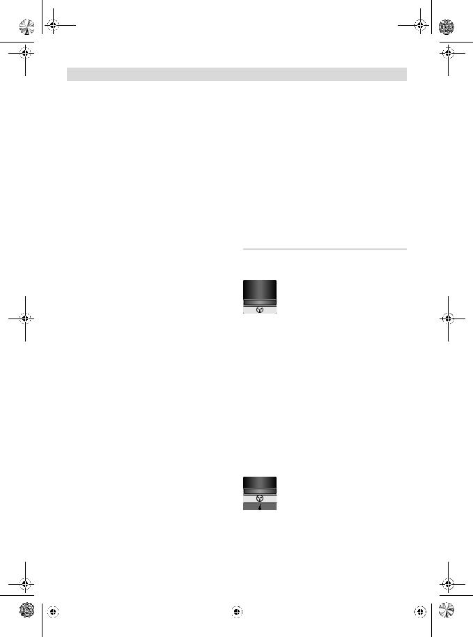
Kaltluftstufe
Luftmenge regelbar, Temperatur festgelegt auf 50 °C (nicht regelbar), kein Programmbetrieb möglich
Die Kaltluftstufe  ist geeignet zum Abkühlen eines erhitzten Werkstücks oder zum Trocknen von Farbe. Sie ist ebenso geeignet, um das Elektrowerkzeug vor dem Abstellen oder dem Wechsel der Aufsatzdüsen abzukühlen.
Beim Wechsel aus der Heißluftstufe  mit höheren Temperaturen dauert es kurze Zeit, bis sich das Elektrowerkzeug auf 50 °C abgekühlt hat.
Während des Abkühlens wird im Display 7 die tatsächliche Temperatur am Düsenausgang angezeigt.
Beim Wechsel aus der Heißluftstufe  zur Kaltluftstufe
  werden die aktuellen Luftmengeneinstellungen übernommen.
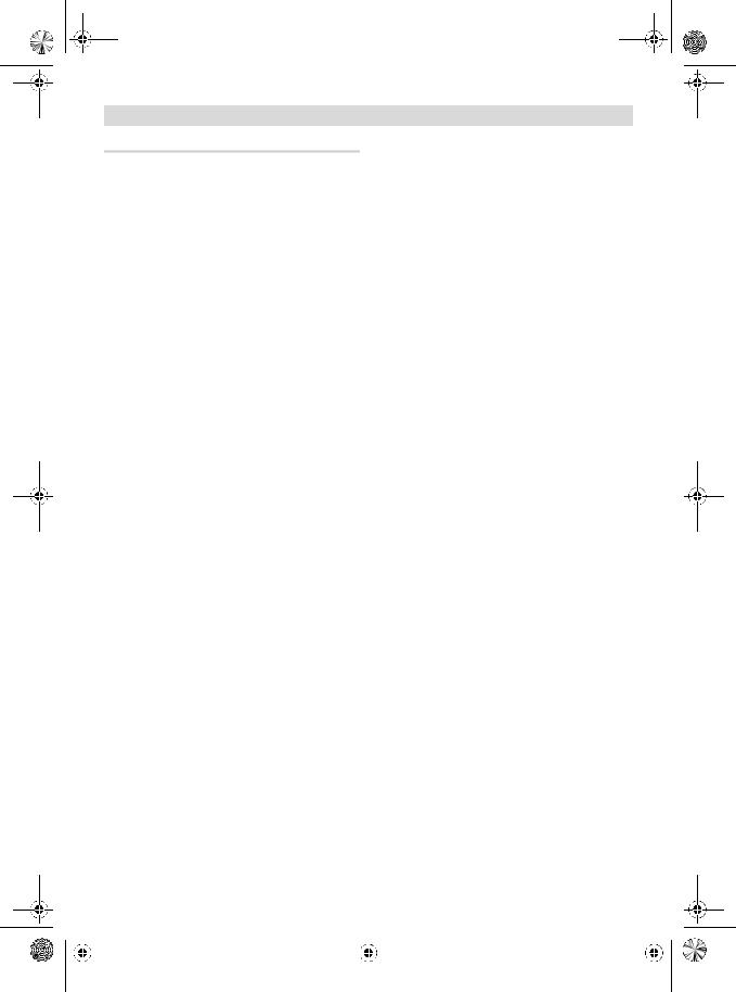
Heißluftstufe
Luftmenge und Temperatur regelbar, Normalund Programmbetrieb möglich
Beim Wechsel von der Kaltluftstufe  zur Heißluftstufe
  werden Luftmenge, Temperatur und gegebenenfalls das Programm automatisch so eingestellt wie beim letzten Betrieb in der Heißluftstufe.
|
|
1 609 929 S53 | (26.11.08) |
|
|
Bosch Power Tools |
|
|
||
|
|
|
|
|
|
|
|
|
|
|
|
|
|
|
|
|
|
|
|
|
|
|
|
|
|
|
|
|
|
OBJ_BUCH-485-002.book Page 11 Wednesday, November 26, 2008 11:54 AM
Programmbetrieb
Im Programmbetrieb können Sie Luftmengenund Temperatureinstellungen dauerhaft in vier Programmen speichern. In jedem Programm sind beliebige Luftmengenund Temperaturkombinationen möglich.
Auch bei Programmbetrieb können Sie Luftmenge und Temperatur jederzeit ändern. Werden die Änderungen nicht gespeichert, gehen sie beim Ausschalten oder beim Wechsel in ein anderes Programm verloren.
Zum Wechsel in den Programmbetrieb drücken Sie die Programmwahltaste 6 so oft, bis die Nummer des gewünschten Programms im Display 7 angezeigt wird.
Bei Auslieferung des Elektrowerkzeugs sind folgende vier Programme voreingestellt:
Programm |
Anwendung |
Temperatur in °C Luftmenge |
|
|
|
1 |
Kunststoffrohre (z.B. LDPE) |
|
|
verformen |
250 |
|
|
|
2 |
Kunststoff (z.B. PVC) ver- |
|
|
schweißen |
350 |
|
|
|
3 |
Lack entfernen/Kleber lösen |
450 |
|
|
|
4 |
Löten |
550 |
|
|
|
Zum Ändern eines vorhandenen Programms wechseln Sie durch Drücken der Programmwahltaste 6 in dieses Programm. Stellen Sie mit den Tasten für Luftmengenregulierung 8 und für Temperaturregulierung 9 die gewünschte Luftmenge und Temperatur ein.
Sobald Sie die Werte eines Programms verändert haben, blinkt links oben im Display das Symbol  . Sind die gewünschte Luftmenge und Temperatur eingestellt, dann drücken Sie die Speichertaste 10 so lange, bis das Zeichen
  im Display erlischt. Die eingestellten Werte sind nun unter der im Display angezeigten Programmnummer gespeichert.
Bosch Power Tools
Deutsch | 11
Normalbetrieb
Zum Wechsel aus dem Programmbetrieb in den Normalbetrieb drücken Sie die Programmwahltaste 6 so oft, bis im Display keine Programmnummer über der Temperatur angezeigt wird.
Luftmenge und Temperatur sind jederzeit mit den Tasten für Luftmengenregulierung 8 und für Temperaturregulierung 9 änderbar.
Die im Normalbetrieb eingestellten Werte für Luftmenge und Temperatur bleiben unter folgenden Bedingungen gespeichert:
–Wechsel in den Programmbetrieb,
–Wechsel in die Kaltluftstufe,
–Ausschalten des Elektrowerkzeugs.
Arbeitshinweise
Hinweis: Bringen Sie die Düse 4 nicht zu nah an das zu bearbeitende Werkstück. Der entstehende Luftstau kann zur Überhitzung des Elektrowerkzeugs führen.
Wärmeschutz abnehmen
Für Arbeiten an besonders engen Stellen können Sie den Wärmeschutz 5 abnehmen.
fVorsicht vor der heißen Düse! Bei Arbeiten ohne Wärmeschutz besteht erhöhte Verbrennungsgefahr.
Zum Abnehmen bzw. Aufsetzen des Wärmeschutzes 5 schalten Sie das Elektrowerkzeug aus und lassen es abkühlen.
Zum schnelleren Abkühlen können Sie das Elektrowerkzeug auch kurz in der Kaltluftstufe laufen lassen.
Schrauben Sie den Wärmeschutz 5 entgegen dem Uhrzeigersinn ab bzw. im Uhrzeigersinn wieder auf.
Elektrowerkzeug abstellen (siehe Bild C)
Stellen Sie das Elektrowerkzeug auf den Ablageflächen 1 ab, um es abkühlen zu lassen oder um beide Hände zum Arbeiten frei zu haben.
fArbeiten Sie mit dem abgestellten Elektrowerkzeug besonders vorsichtig! Sie können sich an der heißen Düse oder am heißen Luftstrom verbrennen.
1 609 929 S53 | (26.11.08)
OBJ_BUCH-485-002.book Page 12 Wednesday, November 26, 2008 11:54 AM
12 | Deutsch
Arbeitsbeispiele
Die Abbildungen der Arbeitsbeispiele finden Sie auf den Ausklappseiten.
Die Temperaturangaben in den Arbeitsbeispielen sind Richtwerte, die je nach Materialbeschaffenheit abweichen können. Der Abstand der Düse richtet sich nach dem zu bearbeitenden Material.
Die optimale Temperatur für die jeweilige Anwendung lässt sich durch praktischen Versuch ermitteln. Beginnen Sie immer mit einer niedrigen Temperaturstufe.
Sie können bei allen Arbeitsbeispielen außer „Lack von Fenstern entfernen“ ohne Zubehör arbeiten. Der Einsatz der vorgeschlagenen Zubehörteile vereinfacht jedoch die Arbeit und erhöht die Qualität des Ergebnisses wesentlich.
fVorsicht beim Düsenwechsel! Berühren Sie die heiße Düse nicht. Lassen Sie das Elektrowerkzeug abkühlen und tragen Sie beim Wechsel Schutzhandschuhe. Sie können sich an der heißen Düse verbrennen.
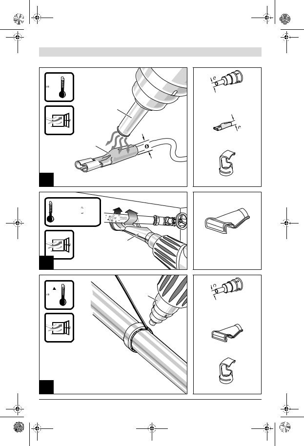
Lack entfernen/Kleber lösen (siehe Bild A)
Setzen Sie die Flächendüse 11 (Zubehör) auf. Weichen Sie den Lack kurz mit Heißluft auf und heben Sie ihn mit einem scharfen, sauberen Spachtel ab. Lange Hitzeeinwirkung verbrennt den Lack und erschwert das Entfernen.
Viele Klebemittel (z.B. Aufkleber) werden durch Wärme weich. Bei erwärmtem Kleber können Sie Verbindungen trennen oder überschüssigen Kleber entfernen.
Lack von Fenstern entfernen (siehe Bild B)
fVerwenden Sie unbedingt die Glasschutzdüse 12 (Zubehör). Es besteht Glasbruchgefahr.
Auf profilierten Flächen können Sie den Lack mit einem passenden Spachtel abheben und mit einer weichen Drahtbürste abbürsten.
Kunststoffrohre verformen (siehe Bild C)
Setzen Sie die Reflektordüse 13 (Zubehör) auf. Füllen Sie Kunststoffrohre mit Sand und verschließen Sie sie auf beiden Seiten, um das Abknicken des Rohres zu verhindern. Erwärmen Sie das Rohr gleichmäßig durch seitliches Hinund Herbewegen.
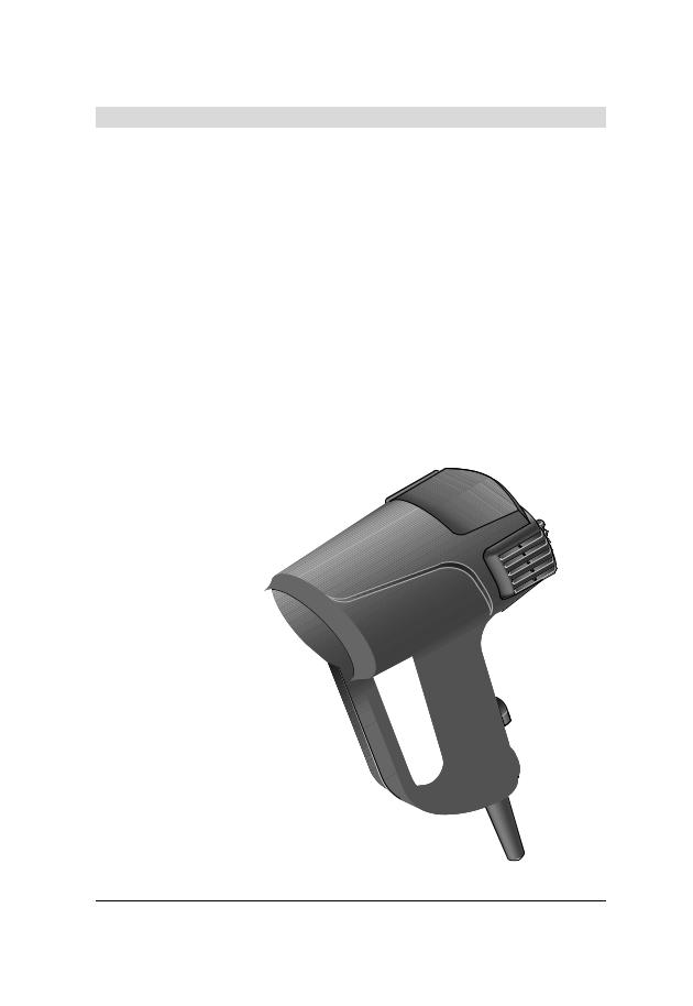
Kunststoff verschweißen (siehe Bild D)
Setzen Sie die Reduzierdüse 16 und den Schweißschuh 15 (beide Zubehör) auf. Die zu verschweißenden Werkstücke und der Schweißdraht 14 (Zubehör) müssen aus dem gleichen Material sein (z.B. beide PVC). Die Naht muss sauber und fettfrei sein.
Erwärmen Sie die Nahtstelle vorsichtig, bis sie teigig wird. Beachten Sie, dass der Temperaturbereich zwischen teigigem und flüssigem Zustand eines Kunststoffes gering ist.
Führen Sie den Schweißdraht 14 zu und lassen Sie ihn in den Spalt einlaufen, sodass eine gleichmäßige Wulst entsteht.
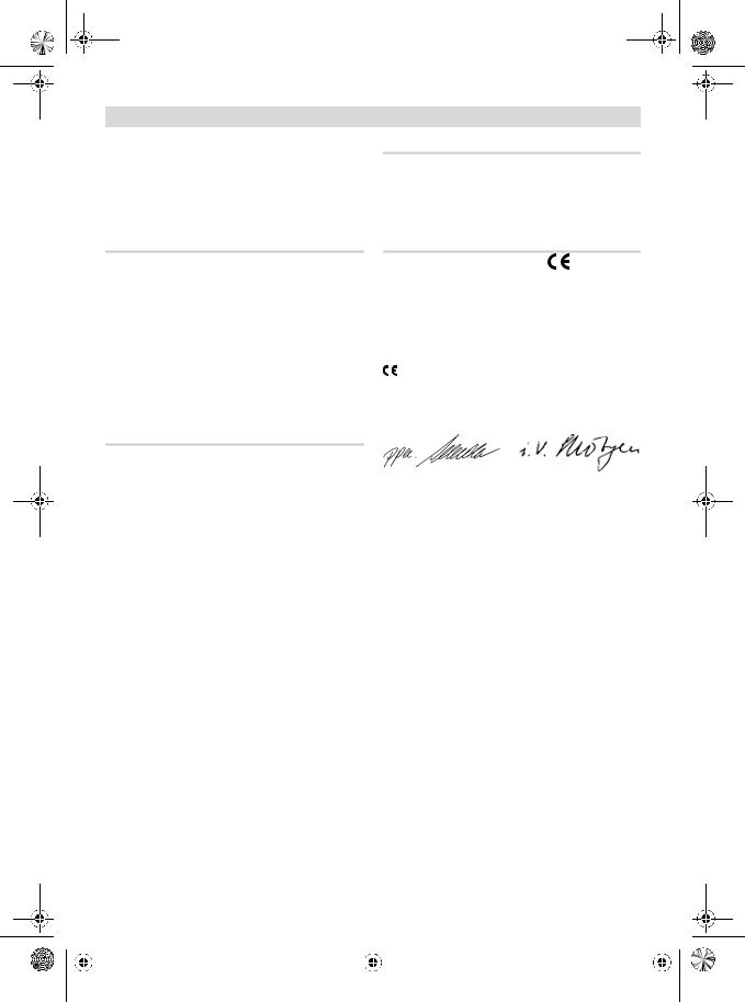
Schrumpfen (siehe Bild E)
Setzen Sie die Reduzierdüse 16 (Zubehör) auf. Wählen Sie den Durchmesser des Schrumpfschlauches 17 (Zubehör) entsprechend dem Werkstück (z.B. Kabelschuh). Erwärmen Sie den Schrumpfschlauch gleichmäßig.
Wasserleitungen auftauen (siehe Bild F)
fPrüfen Sie vor dem Erwärmen, ob es sich tatsächlich um eine Wasserleitung handelt.
Wasserleitungen sind oft äußerlich nicht von Gasleitungen zu unterscheiden. Gasleitungen dürfen keinesfalls erwärmt werden.
Setzen Sie die Winkeldüse 18 (Zubehör) auf. Erwärmen Sie eingefrorene Stellen immer vom Rand zur Mitte.
Erwärmen Sie Kunststoffrohre sowie Verbindungen zwischen Rohrstücken besonders vorsichtig, um Beschädigungen zu vermeiden.
Weichlöten (siehe Bild G)
Setzen Sie für Punktlötungen die Reduzierdüse 16, für das Löten von Rohren die Reflektordüse 13 (beide Zubehör) auf.
Falls Sie Lot ohne Flussmittel verwenden, geben Sie Lötfett oder Lötpaste auf die Lötstelle. Erwärmen Sie die Lötstelle je nach Material ca. 50 bis 120 Sekunden. Geben Sie das Lot zu. Das Lot muss durch die Werkstücktemperatur schmelzen. Entfernen Sie gegebenenfalls nach dem Erkalten der Lotstelle das Flussmittel.
|
|
1 609 929 S53 | (26.11.08) |
|
|
Bosch Power Tools |
|
|
||
|
|
|
|
|
|
|
|
|
|
|
|
|
|
|
|
|
|
|
|
|
|
|
|
|
|
|
|
|
|
 OBJ_BUCH-485-002.book Page 13 Wednesday, November 26, 2008 11:54 AM
Wartung und Service
Wartung und Reinigung
fZiehen Sie vor allen Arbeiten am Elektrowerkzeug den Netzstecker aus der Steckdose.
fHalten Sie das Elektrowerkzeug und die Lüftungsschlitze sauber, um gut und sicher zu arbeiten.
Grobschmutzfilter reinigen
Schieben Sie die Abdeckung 2 mit Grobschmutzfilter nach hinten aus dem Gehäuse. Blasen Sie den Filter aus (z.B. mit Druckluft) oder reinigen Sie ihn mit einer weichen Bürste. Setzen Sie die Abdeckung wieder ein.
Sollte das Elektrowerkzeug trotz sorgfältiger Herstellungsund Prüfverfahren einmal ausfallen, ist die Reparatur von einer autorisierten Kundendienststelle für Bosch-Elektrowerkzeuge ausführen zu lassen.
Geben Sie bei allen Rückfragen und Ersatzteilbestellungen bitte unbedingt die 10-stellige Sachnummer laut Typenschild des Elektrowerkzeuges an.
Deutsch | 13
Deutschland
Robert Bosch GmbH Servicezentrum Elektrowerkzeuge Zur Luhne 2
37589 Kalefeld – Willershausen
Tel. Kundendienst: +49 (1805) 70 74 10 Fax: +49 (1805) 70 74 11
E-Mail: Servicezentrum.Elektrowerkzeuge@de.bosch.com Tel. Kundenberatung: +49 (1803) 33 57 99
Fax: +49 (711) 7 58 19 30
E-Mail: kundenberatung.ew@de.bosch.com
Österreich
ABE Service GmbH Jochen-Rindt-Straße 1 1232 Wien
Tel. Service: +43 (01) 61 03 80 Fax: +43 (01) 61 03 84 91
Tel. Kundenberater: +43 (01) 7 97 22 30 66 E-Mail: abe@abe-service.co.at
Schweiz
Tel.: +41 (044) 8 47 15 11
Fax: +41 (044) 8 47 15 51
Luxemburg
Tel.: +32 (070) 22 55 65
Fax: +32 (070) 22 55 75
E-Mail: outillage.gereedschap@be.bosch.com
Kundendienst und Kundenberatung
Der Kundendienst beantwortet Ihre Fragen zu Reparatur und Wartung Ihres Produkts sowie zu Ersatzteilen. Explosionszeichnungen und Informationen zu Ersatzteilen finden Sie auch unter: www.bosch-pt.com
Das Bosch-Kundenberater-Team hilft Ihnen gerne bei Fragen zu Kauf, Anwendung und Einstellung von Produkten und Zubehören.
www.powertool-portal.de, das Internetportal für Handwerker und Heimwerker. www.ewbc.de, der Informations-Pool für Handwerk und Ausbildung.
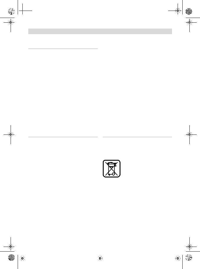
Entsorgung
Elektrowerkzeuge, Zubehör und Verpackungen sollen einer umweltgerechten Wiederverwertung zugeführt werden.
Nur für EU-Länder:
Werfen Sie Elektrowerkzeuge nicht in den Hausmüll!
Gemäß der Europäischen Richtlinie 2002/96/EG über Elektro-
und Elektronik-Altgeräte und ihrer Umsetzung in nationales Recht
müssen nicht mehr gebrauchsfähige Elektrowerkzeuge getrennt gesammelt und einer umweltgerechten Wiederverwertung zugeführt werden.
Änderungen vorbehalten.
|
|
Bosch Power Tools |
|
|
1 609 929 S53 | (26.11.08) |
|
|
||
|
|
|
|
|
|
|
|
|
|
|
|
|
|
|
|
|
|
|
|
|
|
|
|
|
|
|
|
|
|
OBJ_BUCH-485-002.book Page 14 Wednesday, November 26, 2008 1:56 PM
14 | English
Safety Notes
Read all safety warnings and all instructions. Failure to follow the warnings and instructions may result in electric shock, fire and/or serious injury.
fBe careful when working with the power tool. The power tool produces intense heat which can lead to increased danger of fire and explosion.
fExercise special care when working close to inflammable materials. The hot air jet or the hot nozzle can ignite dust or gases.
fDo not operate or work with the power tool in areas where there is danger of explosion.
fNever direct the hot air jet at the same position for longer periods. Easily inflammable gases can develop e.g., when working plastic, paint, varnish or similar materials.
fBe aware that heat can be conducted to hidden covered materials and can ignite them.
fAfter using, place the power tool down in a secure manner and allow it to cool down completely before packing it away. The hot nozzle can cause damage.
fDo not leave the switched-on power tool unattended.
fStore idle power tools out of the reach of children. Do not allow persons unfamiliar with the power tool or these instructions to operate the power tool. Power tools are dangerous in the hands of untrained users.
fDo not expose the power tool to rain or wet conditions. Water entering a power tool will increase the risk of electric shock.
fDo not abuse the cord. Never use the cord for carrying, pulling or unplugging the power tool. Keep cord away from heat, oil, sharp edges or moving parts. Damaged or entangled cords increase the risk of electric shock.
fAlways wear safety goggles. Safety goggles will reduce the risk of injuries.
fDisconnect the plug from the socket outlet before making any adjustments, changing accessories, or placing the power tool aside. This safety measure prevents unintentional starting of the power tool.
fCheck the power tool, cord and plug each time before use. Do not use the power tool if damage is determined. Do not open the power tool yourself and have it serviced only by a qualified repair person using only original spare parts. Damaged power tools, cords and plugs increase the risk of electric shock.
Provide for good ventilation of your working place. Gas and vapour developing during working are often harmful to one’s health.
fWear safety gloves and do not touch the hot nozzle. Danger of burning.
fNever direct the hot air jet against persons or animals.
fDo not use the power tool as a hairdryer.
The hot air being blown out is significantly hotter than that from a hairdryer.
fWhen operating the power tool in damp environments is unavoidable, use a residual current device (RCD). The use of a residual current device (RCD) reduces the risk of an electric shock.
fProducts sold in GB only: Your product is fitted with an approved 13 A (BS 1363/A) electric plug and is protected by a 13 A fuse (ASTA Approved to BS 1362).
If the plug is not suitable for your socket outlets, it should be cut off and an appropriate plug fitted in its place by an authorised customer service agent.
The severed plug must be disposed of to avoid a possible shock hazard and should never be inserted into a 13 A socket elsewhere.
|
|
1 609 929 S53 | (26.11.08) |
|
|
Bosch Power Tools |
|
|
||
|
|
|
|
|
|
|
|
|
|
|
|
|
|
|
|
|
|
|
|
|
|
|
|
|
|
|
|
|
|

OBJ_BUCH-485-002.book Page 15 Wednesday, November 26, 2008 11:54 AM
Functional Description
While reading the operating instructions, unfold the graphics page for the machine and leave it open.
English | 15
Noise Information
Measured values determined according to EN 60745.
Typically the A-weighted sound pressure level of the product is lower than 70 dB(A).
Intended Use
The power tool is intended for the forming and welding of plastic, removal of paint and the warming of heat-shrinkable tubing. It is also suitable for soldering and tinning, loosening of adhesive joints and the defrosting of water lines.
Use the machine only when you can fully assess all functions and handle them without limitation, or after having received appropriate instructions.
Product Features
The numbering of the product features refers to the illustration of the machine on the graphics page.
1Standing surface
2Cover with coarse-debris filter
3On/Off switch with stage selector
4Nozzle
5Heat protection collar
6Program-selection button
7Display
8Button for air-flow control
9Button for temperature control
10Save button
11Wide jet nozzle*
12Glass protection nozzle*
13Reflector nozzle*
14Welding rod*
15Welding shoe*
16Reduction nozzle*
17Heat-shrinkable sleeve*
18Angle nozzle*
*Accessories shown or described are not part of the standard delivery scope of the product. A complete overview of accessories can be found in our accessories program.
Declaration of Conformity
We declare under our sole responsibility that the product described under “Technical Data” is in conformity with the following standards or standardization documents:
EN 60335 according to the provisions of the directives 2006/95/EC, 2004/108/EC.
03 |
|
Dr. Egbert Schneider |
Dr. Eckerhard Strötgen |
Senior Vice President |
Head of Product |
Engineering |
Certification |
Robert Bosch GmbH, Power Tools Division
D-70745 Leinfelden-Echterdingen
Leinfelden, 05.10.2007
|
|
Bosch Power Tools |
|
|
1 609 929 S53 | (26.11.08) |
|
|
||
|
|
|
|
|
|
|
|
|
|
|
|
|
|
|
|
|
|
|
|
|
|
|
|
|
|
|
|
|
|
OBJ_BUCH-485-002.book Page 16 Wednesday, November 26, 2008 11:54 AM
16 | English
Technical Data
Hot Air Gun |
|
GHG 660 LCD |
GHG 660 LCD |
|
|
|
Professional |
Professional |
|
Article number |
|
0 601 944 7.. |
0 601 944 7.. |
|
Rated voltage |
V |
220 |
–240 |
110–120 |
Rated power input |
W |
|
2300 |
1400 |
Air flow |
l/min |
250 |
–500 |
250–500 |
Temperature at the nozzle outlet (approx.) |
°C |
50 |
–660 |
50–600 |
Temperature-measuring accuracy |
|
|
±5 % |
±5 % |
– at the nozzle outlet |
|
|
||
– on the display |
|
|
±5 % |
±5 % |
Display operating temperature* |
°C |
–20...+70 |
–20...+70 |
|
Weight according to EPTA-Procedure 01/2003 |
kg |
|
1.0 |
1.0 |
Protection class |
|
|
/II |
/II |
|
|
|
|
|
* The display can turn black when not within the operating temperature.
Please observe the article number on the type plate of your machine. The trade names of the individual machines may vary.
Operation
Starting Operation
fObserve correct mains voltage! The voltage of the power source must agree with the voltage specified on the nameplate of the machine. Power tools marked with 230 V can also be operated with 220 V.
Switching On and Off
To switch on the power tool, push the On/Off switch 3 to the position (see “Cool-air Stage”, page 17) or
  (see “Hot-air Stage”, page 17).
In both positions, the power tool will start with the previous set air-flow and temperature values.
To switch off, push the On/Off switch 3 to the stop in position “0”.
After working for a longer period at a high temperature, operate the power tool for a short period in the cool-air stage  before switching off.
Thermal-protection shut-off: In case of overheating (e.g. due to air build-up), the power tool automatically shuts off the heating system, but the
blower will continue to run. When the power tool has cooled down to the operating temperature, the heating system is automatically switched on again.
Regulating the Air flow
The air flow can be regulated with the air-flow control button 8:
Minimal air flow
Maximum air flow
To increase the air flow, press on the “+” of the air-flow control button 8, to decrease the air flow, press on the “–”.
Briefly pressing the air-flow control button 8 at the respective position increases or decreases the air flow by one step. Prolonged pressing of the air-flow control button continuously increases or decreases the air flow until the button is released, or the maximum or minimal air flow is reached.
As an example, reduce the air flow when the surrounding area of a workpiece is not to be heated excessively or when a light workpiece could be moved away by the air flow.
|
|
1 609 929 S53 | (26.11.08) |
|
|
Bosch Power Tools |
|
|
||
|
|
|
|
|
|
|
|
|
|
|
|
|
|
|
|
|
|
|
|
|
|
|
|
|
|
|
|
|
|
OBJ_BUCH-485-002.book Page 17 Wednesday, November 26, 2008 11:54 AM
Setting the Temperature
The temperature can only be regulated in the hot-air stage  .
.
To increase the temperature, press on the “+” of the temperature-control button 9, to decrease the temperature, press on the “–”.
Briefly pressing the temperature-control button 9 at the respective position increases or decreases the temperature by 10 °C. Prolonged pressing of the temperature-control button continuously increases or decreases the temperature by 10 °C, until the button is released or the maximum or minimal temperature is reached.
After a change to the temperature setting, the power tool requires a short period to warm up or cool down the air flow. During this period, the target temperature is indicated between the flashing arrows in the display 7. When the target temperature is reached, the arrows go out and the display indicates the actual temperature.
Activating/Deactivating the Button Lock (“LOC”)
To prevent accidental changing of the air flow and temperature  the function of buttons 6, 8, 9 and 10 can be locked when in the hot-air stage. In the cool-air stage
  the air flow can be changed even when the button lock is activated.
Activating the Button Lock:
Switch the power tool on while in the hot-air stage  . Adjust the air-flow and temperature settings to be locked.
Switch the power tool off.
Press and hold the save button 10 and switch the power tool on again (in cool-air or hot-air stage). The display 7 will indicate “OFF” for the deactivated button lock.
With the save button 10 still held, press one after the other:
–“+” on the temperature-control button 9,
–“+” on the air-flow control button 8,
–“–” on the temperature-control button 9,
–“–” on the air-flow control button 8.
The display indicates “ON”. Release the save button 10.
English | 17
The button lock is now activated. The preset values for temperature and air flow are indicated in the hot-air stage  . After pushing any button, “LOC” is indicated in the display and the values cannot be changed.
Deactivating the Button Lock:
Switch the power tool off. Push and hold the save button 10 and switch the power tool on again. The display indicates “ON” for the activated button lock. Push the temperature button 9 and the air-flow control button 8 in the same sequence as when activating the button lock. The display indicates “OFF” for the deactivated button lock.
Operating Modes
Cool-air Stage
The air flow can be regulated, the temperature is set to 50 °C (cannot be regulated), and programming operation is not possible.
The cool-air stage  is suitable for cooling down a heated-up workpiece or for drying paint. It is also suitable for cooling down the power tool before placing it down or changing nozzles.
When changing from the hot-air stage  with higher temperatures, it will take a few moments until the power tool has cooled down to 50 °C. During cooling down, the display 7 indicates the actual temperature at the nozzle outlet.
When changing from the hot-air stage  to the cool-air stage
  , the current air-flow settings are taken over.
Hot-air Stage
The air flow and temperature can be regulated; normal and programming operation are possible.
When changing from the cool-air stage  to the hot-air stage
  , the air flow, temperature and possibly the program are automatically adjusted according to the settings of the last hot-air stage operation.
|
|
Bosch Power Tools |
|
|
1 609 929 S53 | (26.11.08) |
|
|
||
|
|
|
|
|
|
|
|
|
|
|
|
|
|
|
|
|
|
|
|
|
|
|
|
|
|
|
|
|
|
OBJ_BUCH-485-002.book Page 18 Wednesday, November 26, 2008 11:54 AM
18 | English
Programming Operation
In programming operation, it is possible to continuously store the air-flow and temperature adjustments in four programs. Each program allows for different air-flow and temperature combinations.
In progamming operation, it is also possible to change the air flow and temperature any time. When the changes are not saved, they are lost after switching off or changing to a different program.
To change to programming operation, press the program-selection button 6 until the number of the requested program is indicated in the display 7.
The following four programs are preset in the condition of delivery:
Program |
Application |
Temperature in °C Air Flow |
|
|
|
1 |
Deforming plastic tubing |
|
|
(e.g. LDPE) |
250 |
|
|
|
2 |
Welding plastic (e.g. PVC) |
350 |
|
|
|
3 |
Removing Varnish/ |
|
|
Softening Adhesives |
450 |
|
|
|
4 |
Soldering |
550 |
To change a set program, switch to this program by pressing the program-selection button 6. Set the requested air flow and temperature with the air-flow control button 8 and the temperaturecontrol button 9.
As soon as the settings of a program have been changed, the  symbol flashes in the left top of the display. Once the requested air flow and temperature are set, press the save button 10 until the
  symbol in the display goes out. The set values are now stored under the program number indicated in the display.
Normal Operation
To switch from programming operation to normal operation, press the program-selection button 6 as often as required until no program number is indicated above the temperature in the display. The air flow and temperature can be changed anytime with the air-flow control button 8 and the temperature-control button 9.
Under the following conditions, the values for air flow and temperature set in normal operation will remain stored:
–When changing to programming operation,
–When changing to the cool-air stage,
–When switching the power tool off.
Working Advice
Note: Do not apply the nozzle 4 too close to the workpiece being worked. The hot air build-up can lead to overheating of the power tool.
Removing the Heat Protection
The heat protection collar 5 can be removed when working at particularly hard-to-reach locations.
fBe careful of the hot nozzle! Increased danger of burning exists when working without the heat protection collar.
To remove or mount the heat protection collar 5, switch the power tool off and allow it to cool down.
To cool down the power tool more quickly, you can operate it for a few moments in the cool-air stage.
Turn the heat protection collar 5 in anticlockwise direction to remove and in clockwise direction to mount again.
Placing Down the Power Tool (see figure C)
To cool down the power tool or have both hands free, place it down on the standing surface 1.
fBe especially careful when working with the placed down power tool! There is danger of burning oneself on the hot nozzle or on the hot air jet.
|
|
1 609 929 S53 | (26.11.08) |
|
|
Bosch Power Tools |
|
|
||
|
|
|
|
|
|
|
|
|
|
|
|
|
|
|
|
|
|
|
|
|
|
|
|
|
|
|
|
|
|

OBJ_BUCH-485-002.book Page 19 Wednesday, November 26, 2008 11:54 AM
Work Examples
The illustrations of the work examples can be found on the fold-out pages.
The temperature settings in the work examples are reference values that can vary, depending on the material characteristics. The distance between the nozzle and the workpiece depends on the material to be worked.
The optimal temperature for the respective application can be determined by practical testing. Always start with a low temperature setting.
All application examples can be performed without accessories except for “Removing Varnish/ Paint from Windows”. However, the use of recommended accessories simplifies the work and significantly improves the quality of the result.
fBe careful when changing the nozzle! Do not touch the hot nozzle. Allow the power tool to cool down and wear protective gloves while changing the nozzle. Danger of burning oneself on the hot nozzle.
Removing Varnish/Softening Adhesives (see figure A)
Mount the wide jet nozzle 11 (accessory). Briefly soften the varnish applying hot air and remove it using a sharp, clean scraper or putty knife.
Applying heat too long will burn the varnish, making it more difficult to remove.
Many adhesives (e.g. of stickers) become soft when heated. Heated adhesives allow for bonds to be separated or excessive adhesive to be removed.
Removing Varnish/Paint from Windows (see figure B)
fUse of the glass protection nozzle 12 (accessory) is essential. Danger of glass breaking.
On profiled surfaces, varnish can be removed using an appropriately fitting spatula and brushed off with a soft wire brush.
Shaping Plastic Tubing (see figure C)
Mount the reflector nozzle 13 (accessory). To avoid kinking of the tubing, fill the tubing with sand and plug both ends. Heat the tubing evenly by by applying the heat from side to side.
English | 19
Welding Plastics (see figure D)
Mount the reduction nozzle 16 and the welding shoe 15 (both accessories). The workpieces to be welded and the welding rod 14 (accessory) must be of the same material (e.g. both of PVC). The seam must be clean and grease-free.
Carefully heat up the seam location until it becomes doughy. Please note that the temperature difference between the doughy and liquid state of plastic is low.
Feed in the welding rod 14 and allow it to run into the gap so that a uniform bead is produced.
Shrinking (see figure E)
Mount the reduction nozzle 16 (accessory). Select the diameter of the heat-shrinkable sleeve 17 (accessory) according to the workpiece (e.g. a cable lug). Heat the heat-shrinkable sleeve evenly.
Defrosting Water Pipes (see figure F)
fBefore heating pipes, check to make sure that it is actually a water pipe. Water lines often do not differ in appearance from gas lines. Gas lines are not to be heated under any circumstances.
Place on the angle nozzle 18 (accessory). Heat the frozen zone always from the outside to the middle.
Heat up plastic pipes as well as connections between pipe pieces especially careful to prevent damage.
Soft Soldering (see figure G)
For point soldering, place on the reduction nozzle 16, for the soldering of pipes/tubing, place on the reflector nozzle 13 (both accessories).
If solder without flux is used, apply soldering grease or paste to the location to be soldered. Warm the location to be soldered for
50–120 seconds depending on the material. Apply the solder. The solder must melt from the workpiece temperature. After the soldered location has cooled, remove the flux.
|
|
Bosch Power Tools |
|
|
1 609 929 S53 | (26.11.08) |
|
|
||
|
|
|
|
|
|
|
|
|
|
|
|
|
|
|
|
|
|
|
|
|
|
|
|
|
|
|
|
|
|
 OBJ_BUCH-485-002.book Page 20 Wednesday, November 26, 2008 11:54 AM
20 | English
Maintenance and Service
Maintenance and Cleaning
fBefore any work on the machine itself, pull the mains plug.
fFor safe and proper working, always keep the machine and ventilation slots clean.
Cleaning the Coarse-debris Filter
Pull the cover with coarse-debris filter 2 toward the rear out of the housing. Blow out the filter (e.g. with compressed-air) or clean it with a soft brush. Reattach the cover with coarse-debris filter.
If the machine should fail despite the care taken in manufacturing and testing procedures, repair should be carried out by an after-sales service centre for Bosch power tools.
In all correspondence and spare parts order, please always include the 10-digit article number given on the type plate of the machine.
Ireland
Origo Ltd.
Unit 23 Magna Drive
Magna Business Park City West
Dublin 24
Tel. Service: +353 (01) 4 66 67 00 Fax: +353 (01) 4 66 68 88
Australia, New Zealand and Pacific Islands
Robert Bosch Australia Pty. Ltd. Power Tools
Locked Bag 66
Clayton South VIC 3169
Customer Contact Center Inside Australia:
Phone: +61 (01300) 307 044 Fax: +61 (01300) 307 045 Inside New Zealand:
Phone: +64 (0800) 543 353 Fax: +64 (0800) 428 570 Outside AU and NZ: Phone: +61 (03) 9541 5555 www.bosch.com.au
After-sales Service and Customer Assistance
Our after-sales service responds to your questions concerning maintenance and repair of your product as well as spare parts. Exploded views and information on spare parts can also be found under:
www.bosch-pt.com
Our customer consultants answer your questions concerning best buy, application and adjustment of products and accessories.
Great Britain
Robert Bosch Ltd. (B.S.C.)
P.O. Box 98
Broadwater Park
North Orbital Road
Denham
Uxbridge
UB 9 5HJ
Tel. Service: +44 (0844) 736 0109
Fax: +44 (0844) 736 0146
E-Mail: SPT-Technical.de@de.bosch.com
Disposal
The machine, accessories and packaging should be sorted for environmental-friendly recycling.
Only for EC countries:
Do not dispose of power tools into household waste!
According the European Guideline 2002/96/EC for Waste Electrical and Electronic Equipment and its
implementation into national right, power tools that are no longer usable must be collected separately and disposed of in an environmentally correct manner.
Subject to change without notice.
|
|
1 609 929 S53 | (26.11.08) |
|
|
Bosch Power Tools |
|
|
||
|
|
|
|
|
|
|
|
|
|
|
|
|
|
|
|
|
|
|
|
|
|
|
|
|
|
|
|
|
|
OBJ_BUCH-485-002.book Page 21 Wednesday, November 26, 2008 11:54 AM
Consignes de sécurité
Lire tous les avertissements et indications. Le non-respect des avertissements et instructions indiqués ci-après peut entraîner un choc électrique, un incendie et/ou de graves blessures sur les personnes.
fManier avec précaution l’outil électroportatif. L’outil électroportatif génère des températures élevées qui constituent un danger élevé d’incendie et d’explosion.
fEtre extrêmement vigilant lors du travail à proximité de matériaux inflammables. Le courant d’air chaud ou la buse brûlante peuvent enflammer la poussière ou les gaz.
fNe pas utiliser l’outil électroportatif dans un environnement présentant des risques d’explosion.
fNe pas diriger le courant d’air chaud sur le même endroit pendant une période assez longue. Lors du travail de matières plastiques, de peintures, de laques ou d’autres matériaux similaires, des gaz facilement inflammables peuvent être générés.
fFaire attention que la chaleur peut se propager vers des matériaux cachés inflammables et les enflammer.
fAprès son utilisation, poser l’outil électroportatif en toute sécurité et le laisser complètement refroidir avant de le stocker.
La buse brûlante peut causer des dégâts.
fNe pas laisser l’outil électroportatif mis en marche sans surveillance.
fGarder les outils électroportatifs non utilisés hors de portée des enfants. Ne pas permettre l’utilisation de l’outil électroportatif à des personnes qui ne se sont pas familiarisées avec celui-ci ou qui n’ont pas lu ces instructions. Les outils électroportatifs sont dangereux lorsqu’ils sont utilisés par des personnes non initiées.
fNe pas exposer l’outil électroportatif à la pluie ou à l’humidité. La pénétration d’eau dans un outil électroportatif augmente le risque d’un choc électrique.
Français | 21
fNe pas utiliser le câble à d’autres fins que celles prévues, ne pas utiliser le câble pour porter l’outil électroportatif ou pour l’accrocher ou encore pour le débrancher de la prise de courant. Maintenir le câble éloigné des sources de chaleur, des parties grasses, des bords tranchants ou des parties de l’appareil en rotation. Un câble endommagé ou torsadé augmente le risque d’un choc électrique.
fPorter toujours des lunettes de protection.
Des lunettes de protection réduisent le risque de blessures.
fRetirer la fiche de la prise de courant avant d’effectuer des réglages sur l’appareil, de changer les accessoires, ou de ranger l’outil électroportatif. Cette mesure de précaution empêche une mise en fonctionnement de l’outil électroportatif par mégarde.
fAvant toute utilisation, contrôler l’outil électroportatif, la fiche et le câble. Ne pas utiliser l’outil électroportatif si des défauts sont constatés. Ne pas ouvrir l’outil électroportatif soi-même et ne le faire réparer que par une personne qualifiée et seulement avec des pièces de rechange d’origine. Des outils électroportatifs, un câble et/ou une fiche endommagés augmentent le risque d’un choc électrique.
Bien aérer la place de travail.
Les gaz et vapeurs générés lors du travail sont nuisibles à la santé.
fPorter des gants de protection et ne pas toucher la buse chaude. Il y a risque de brûlure !
fNe pas diriger le courant d’air chaud vers des personnes ou des animaux.
fNe pas utiliser l’outil électroportatif comme sèche-cheveux. Le courant d’air qui sort est beaucoup plus chaud que celui d’un sèchecheveux.
fSi l’usage d’un outil électrique dans un emplacement humide est inévitable, utiliser une alimentation protégée par un dispositif à courant différentiel réduit (RCD). L’usage d’un RCD réduit le risque d’un choc électrique.
|
|
Bosch Power Tools |
|
|
1 609 929 S53 | (26.11.08) |
|
|
||
|
|
|
|
|
|
|
|
|
|
|
|
|
|
|
|
|
|
|
|
|
|
|
|
|
|
|
|
|
|

OBJ_BUCH-485-002.book Page 22 Wednesday, November 26, 2008 11:54 AM
22 | Français
Description du fonctionnement
Déplier le volet sur lequel l’appareil est représenté de manière graphique. Laisser le volet déplié pendant la lecture de la présente notice d’utilisation.
Utilisation conforme
L’outil électroportatif est conçu pour les travaux de déformation et de soudage de matières plastiques, d’enlèvement de couches de peinture ainsi que pour le réchauffement de gaines thermorétractables. Il est également approprié pour les travaux de brasage et d’étainage, de détachement de joints collés ainsi que pour la décongélation des conduites d’eau gelées.
N’utilisez l’outil électroportatif que lorsque vous vous rendez compte de toutes ses fonctions et êtes capable de l’utiliser sans réserves ou après avoir reçu des instructions correspondantes.
11Buse large*
12Buse protection du verre*
13Buse réfléchissante*
14Baguette de soudage*
15Aide-soudage*
16Buse réductrice*
17Gaine thermorétractable*
18Buse angulaire*
*Les accessoires décrits ou montrés ne sont pas compris dans l’emballage standard. Vous trouverez les accessoires complets dans notre programme d’accessoires.
Informations concernant les bruits
Valeurs de mesure déterminées conformément à EN 60745.
Le niveau sonore réel de l’outil électroportatif est inférieur à 70 dB(A).
Eléments de l’appareil
La numérotation des éléments de l’appareil se réfère à la représentation de l’outil électroportatif sur la page graphique.
1Support de l’appareil
2Couvercle avec filtre à poussières grossières
3Interrupteur Marche/Arrêt avec réglage de la position
4Buse
5Protection thermique
6Touche de sélection du programme
7Afficheur
8Touche de réglage du débit d’air
9Touche de réglage de la température
10Touche de mémorisation
Déclaration de conformité
Nous déclarons sous notre propre responsabilité que le produit décrit sous « Caractéristiques techniques » est en conformité avec les normes ou documents normatifs suivants : EN 60335 conformément aux termes des réglementations 2006/95/CE, 2004/108/CE.
03 |
|
Dr. Egbert Schneider |
Dr. Eckerhard Strötgen |
Senior Vice President |
Head of Product |
Engineering |
Certification |
Robert Bosch GmbH, Power Tools Division
D-70745 Leinfelden-Echterdingen
Leinfelden, 05.10.2007
|
|
1 609 929 S53 | (26.11.08) |
|
|
Bosch Power Tools |
|
|
||
|
|
|
|
|
|
|
|
|
|
|
|
|
|
|
|
|
|
|
|
|
|
|
|
|
|
|
|
|
|
OBJ_BUCH-485-002.book Page 23 Wednesday, November 26, 2008 11:54 AM
|
|
|
Français | 23 |
|
|
|
|
Caractéristiques techniques |
|
|
|
|
|
|
|
Ventilateur d’air chaud |
|
GHG 660 LCD |
GHG 660 LCD |
|
|
Professional |
Professional |
N° d’article |
|
0 601 944 7.. |
0 601 944 7.. |
Tension nominale |
V |
220–240 |
110–120 |
Puissance absorbée nominale |
W |
2300 |
1400 |
Débit d’air |
l/min |
250–500 |
250–500 |
Température à la sortie de la buse, env. |
°C |
50–660 |
50–600 |
Précision de mesure de la température |
|
±5 % |
±5 % |
– à la sortie de la buse |
|
||
– dans l’affichage |
|
±5 % |
±5 % |
Température de service de l’afficheur* |
°C |
–20...+70 |
–20...+70 |
Poids suivant EPTA-Procédure 01/2003 |
kg |
1,0 |
1,0 |
Classe de protection |
|
/II |
/II |
|
|
|
|
* Il est possible que l’afficheur devienne noir quand il est en dehors de la température de service.
Respectez impérativement le numéro d’article se trouvant sur la plaque signalétique de l’outil électroportatif. Les désignations commerciales des différents outils électroportatifs peuvent varier.
Mise en marche
Mise en service
fTenez compte de la tension du réseau !
La tension de la source de courant doit coïncider avec les indications se trouvant sur la plaque signalétique de l’outil électroportatif. Les outils électroportatifs marqués 230 V peuvent également être mis en service sous 220 V.
Mise en Marche/Arrêt
Pour mettre en marche l’outil électroportatif, poussez l’interrupteur Marche/Arrêt 3 en position  (voir « Air froid », page 25) ou
  (voir
(voir
« Air chaud », page 25).
Dans les deux positions, l’outil électroportatif démarre avec les valeurs du débit d’air et de température réglés avant le dernier arrêt de l’outil électroportatif.
Pour arrêter, poussez l’interrupteur Marche/ Arrêt 3 jusqu’à la butée en position « 0 ».
Après avoir travaillé longtemps à une haute température, faites travailler l’outil électroportatif pendant une courte durée dans la position air froid  pour le laisser refroidir avant de l’arrêter.
Arrêt de sécurité thermique : Dans le cas de surchauffage (par ex. causé par une retenue d’air), l’outil électroportatif arrête automatiquement le chauffage ; le ventilateur, cependant, continue à souffler. Une fois que l’outil électroportatif s’est refroidi et a atteint sa température de service, le chauffage et automatiquement remis en fonction.
|
|
Bosch Power Tools |
|
|
1 609 929 S53 | (26.11.08) |
|
|
||
|
|
|
|
|
|
|
|
|
|
|
|
|
|
|
|
|
|
|
|
|
|
|
|
|
|
|
|
|
|

OBJ_BUCH-485-002.book Page 24 Wednesday, November 26, 2008 11:54 AM
24 | Français
Réglage du débit d’air
La touche 8 permet de régler le débit d’air :
débit d’air minimal débit d’air maximal
Pour augmenter le débit d’air, appuyez sur la touche de réglage du débit d’air 8 sur « + », pour réduire le débit d’air, appuyez sur « – ».
Appuyer brièvement sur la touche 8 augmente ou réduit le débit d’air d’une position. Appuyer plus longtemps sur la touche augmente ou réduit le débit d’air en continu jusqu’à ce que la touche soit relâchée ou que le débit d’air maximal ou minimal soit atteint.
Réduisez le débit d’air par ex. quand l’environnement d’un outil ne doit pas être trop chauffé ou quand un outil léger pourrait être déplacé par le courant d’air.
Régulation de la température
La température ne peut être réglée que dans la position  air chaud.
Pour augmenter la température, appuyez sur la touche de réglage de la température 9 sur « + », pour réduire la température, appuyez sur « – ».
Appuyer brièvement sur la touche 9 augmente ou réduit la température de 10 °C. Appuyer plus longtemps sur la touche augmente ou réduit la température en continu de 10 °C jusqu’à ce que la touche soit relâchée ou que température maximale ou minimale soit atteinte.
Dans le cas d’une modification du réglage de la température, l’outil électroportatif a besoin d’une courte durée pour chauffer ou refroidir le courant d’air. Pendant ce temps, la température cible est affichée dans l’afficheur 7 entre des flèches clignotantes. Une fois la température cible atteinte, les flèches s’éteignent et l’afficheur affiche la température actuelle.
Activer/désactiver le blocage de touche (« LOC »)
Pour éviter une modification par mégarde du débit d’air et de la température, vous pouvez bloquer  la fonction des touches 6, 8, 9 et 10 en position d’air chaud. Dans la position d’air froid
  il est possible de modifier le débit d’air même si le blocage de touche est activé.
Activer le blocage de touche :
Mettez en marche l’outil électroportatif dans la position air chaud  . Réglez les valeurs pour le débit d’air et la température, avec lesquelles l’outil électroportatif doit être bloqué.
Arrêter l’outil électroportatif.
Maintenez appuyé la touche de mémorisation 10 et remettez en marche l’outil électroportatif (position air froid ou air chaud). Dans l’afficheur 7, « OFF » est affiché pour le blocage de touche désactivé.
Appuyez, l’une après l’autre (la touche de mémorisation toujours appuyée 10) sur :
–« + » sur la touche de température 9,
–« + » sur la touche du débit d’air 8,
–« – » sur la touche de température 9,
–« – » sur la touche du débit d’air 8.
« ON » apparaît sur l’afficheur. Relâchez la touche de mémorisation 10.
Le blocage de touche est alors activé. Dans la position air chaud  , les valeurs présélectionnées pour température et débit d’air sont affichées. Lorsqu’on appuye sur une touche quelconque, « LOC » apparaît sur l’écran, il est impossible de modifier les valeurs.
Désactiver le blocage de touche :
Arrêtez l’outil électroportatif. Maintenez appuyé la touche de mémorisation 10 et remettez-le en marche. Dans l’afficheur « ON » est affiché pour le blocage de touche activé. Appuyez sur la touche de température 9 et la touche du débit d’air 8 dans le même ordre que pour activer le blocage de touche. Dans l’afficheur, « OFF » est affiché, le blocage de touche est désactivé.
|
|
1 609 929 S53 | (26.11.08) |
|
|
Bosch Power Tools |
|
|
||
|
|
|
|
|
|
|
|
|
|
|
|
|
|
|
|
|
|
|
|
|
|
|
|
|
|
|
|
|
|
OBJ_BUCH-485-002.book Page 25 Wednesday, November 26, 2008 11:54 AM
Mode opératoire
Air froid
Le débit d’air est réglable, la température est réglée sur 50 °C (pas réglable), le mode programmé n’est pas possible.
La position air froid  est appropriée pour refroidir une pièce chauffée ou pour sécher de la peinture. Elle est également appropriée pour refroidir l’outil électroportatif avant de l’arrêter ou avant de changer les buses.
Lors du changement de la position d’air chaud avec des températures élevées il ne faut que peu de temps jusqu’à ce que l’outil électroportatif se refroidisse à 50 °C. Durant le refroidissement, la température actuelle à la sortie de la buse est affichée dans l’afficheur 7.
Lors du changement de la position d’air chaud à la position d’air froid
  , les réglages actuelles du débit d’air sont repris.
Air chaud
Le débit d’air et la température sont réglables, le mode normal et le mode programmé sont possibles.
Lors du changement de la position air froid  à la position d’air chaud
  , le débit d’air, la température et, le cas échéant, le programme sont automatiquement réglés comme lors de la dernière mise en service en position d’air chaud.
Mode programmé
En mode programmé, vous pouvez mémoriser de manière permanente les réglages du débit d’air et de la température en quatre programmes. Dans chaque programme, toutes les combinaisons de débit d’air et de température sont possibles.
Dans le mode programmé, il est également possible de modifier à tout temps le débit d’air et la température. Si les modifications ne sont pas mémorisées, elles se perdent lors de l’arrêt ou du changement dans un autre programme.
Pour changer dans le mode programmé, appuyez sur la touche de sélection du programme 6 jusqu’à ce que le numéro du programme souhaité soit affiché dans l’afficheur 7.
Français | 25
Lors de la livraison de l’outil électroportatif, les quatre programmes suivants sont préréglés :
Programme |
Utilisation |
Température en °C Débit d’air |
|
|
|
1 |
Déformation de tuyaux |
|
|
en matière plastique |
|
|
(par ex. LD-PE) |
250 |
|
|
|
2 |
Soudage de matières |
|
|
plastiques (par ex. PVC) |
350 |
|
|
|
3 |
Elimination de vernis/ |
|
|
sde colle |
450 |
|
|
|
4 |
Brasage |
550 |
|
|
|
Pour modifier un programme réglé, passez dans ce programme en appuyant sur la touche de sélection du programme 6. A l’aide des touches de réglage du débit d’air 8 et de la température 9, réglez le débit d’air et la température souhaités.
Dès que vous avez modifié les valeurs d’un programme, dans l’afficheur, en haut à gauche, clignote le symbole  . Une fois le débit d’air et la température souhaités réglés, appuyez sur la touche de mémorisation 10 jusqu’à ce que le symbole
  s’éteigne dans l’afficheur. Les valeurs réglées sont alors mémorisées sous le numéro du programme indiqué dans l’afficheur.
Mode normal
Pour changer du mode programmé au mode normal, appuyez la touche de sélection du programme 6 jusqu’à ce que l’afficheur n’affiche plus de numéro de programme au-dessus de la température. A l’aide des touches de réglage du débit d’air 8 et de la température 9, il est à tout temps possible de régler le débit d’air et la température.
Les valeurs du débit d’air et de température réglées en mode normal, restent mémorisées dans les conditions suivantes :
–changement en mode normal,
–changement en position d’air froid,
–arrêt de l’outil électroportatif.
|
|
Bosch Power Tools |
|
|
1 609 929 S53 | (26.11.08) |
|
|
||
|
|
|
|
|
|
|
|
|
|
|
|
|
|
|
|
|
|
|
|
|
|
|
|
|
|
|
|
|
|
OBJ_BUCH-485-002.book Page 26 Wednesday, November 26, 2008 11:54 AM
26 | Français
Instructions d’utilisation
Note : Ne pas trop approcher la buse 4 de la pièce à travailler. La retenue d’air qui en résulte risque de surchauffer l’outil électroportatif.
Enlever la protection thermique
Pour effectuer des travaux dans des endroits d’accès difficile, il est possible d’enlever la protection thermique 5.
fAttention à la buse chaude ! Il y a risque élevé de brûlures pendant les travaux sans protection thermique.
Pour enlever ou monter la protection thermique 5, arrêter l’outil électroportatif et le laisser refroidir.
Pour refroidir l’outil électroportatif plus rapidement, vous pouvez le laisser fonctionner en position d’air froid pour une courte durée.
Dévisser la protection thermique 5 dans le sens inverse des aiguilles d’une montre et la revisser dans le sens des aiguilles d’une montre.
Déposer l’outil électroportatif (voir figure C)
Déposez l’outil électroportatif sur les supports 1 pour le laisser refroidir ou pour avoir les deux mains libres pour travailler.
fEtre extrêmement prudent lors du travail avec l’outil électroportatif déposé ! Il y a risque de se brûler à la buse brûlante ou avec le courant d’air chaud.
Exemples d’utilisation
Vous trouverez les figures avec les exemples d’utilisation sur les volets dépliants.
Les indications de température dans les exemples d’utilisation sont des valeurs à titre indicatif qui peuvent différer suivant la nature du matériau utilisé. La distance de la buse dépend du matériau à travailler.
La température optimale pour chaque utilisation peut être déterminée par des essais pratiques. Commencer toujours à une valeur de température basse.
Il est possible de travailler sans accessoires pour toutes les utilisations, à l’exception de
« Enlever le vernis des fenêtres ». Le fait d’utiliser les accessoires recommandés simplifie cependant le travail et augmente dans une large mesure la qualité du résultat.
fAttention lors du remplacement de la buse ! Ne pas toucher la buse brûlante. Laisser l’outil électroportatif se refroidir et porter des gants de protection pendant le remplacement. Il y a risque de se brûler à la buse brûlante.
Elimination de vernis/sde colle (voir figure A)
Monter la buse large 11 (accessoire). Ramollir le vernis brièvement avec de l’air chaud et le soulever à l’aide d’un grattoir propre et tranchant. Une longue exposition à la chaleur brûle le vernis et rend difficile son élimination.
Beaucoup de colles (par ex. autocollants) s’assouplissent sous l’influence de la chaleur. Lorsque la colle et chauffée, il est possible de séparer des connexions ou d’éliminer l’excédent de colle.
Enlever le vernis des fenêtres (voir figure B)
fUtiliser impérativement la buse protection du verre 12 (accessoire). Le verre risque de se casser.
Sur les surfaces profilées, il est possible de soulever le vernis au moyen d’une spatule appropriée et de l’enlever au moyen d’une brosse métallique souple.
Déformation des tuyaux en plastique (voir figure C)
Monter la buse réfléchissante 13 (accessoire). Remplir les tuyaux en plastique de sable et les fermer des deux côtés pour éviter que le tuyau ne se plie en deux. Chauffer le tuyau de façon homogène par un mouvement de va et vient.
|
|
1 609 929 S53 | (26.11.08) |
|
|
Bosch Power Tools |
|
|
||
|
|
|
|
|
|
|
|
|
|
|
|
|
|
|
|
|
|
|
|
|
|
|
|
|
|
|
|
|
|
OBJ_BUCH-485-002.book Page 27 Wednesday, November 26, 2008 11:54 AM
Soudage de matières plastiques (voir figure D)
Monter la buse réductrice 16 et l’aide-soudage 15 (accessoires). Les pièces à souder et la baguette de soudage 14 doivent être du même matériau (par ex. toutes les deux en PVC). La soudure doit être propre et exempte de gras.
Chauffer avec précaution la soudure jusqu’à ce qu’elle devienne molle. Tenir compte du fait que la plage de température entre l’état mou et l’état liquide des matières plastiques est faible.
Amener la baguette de soudage 14 et la faire couler dans la fente de sorte qu’un cordon régulier se forme.
Retirer (voir figure E)
Monter la buse réductrice 16 (accessoire). Choisir le diamètre de la gaine thermorétractable 17 (accessoire) en fonction de la pièce à travailler (par ex. cosse de câble). Chauffer la gaine thermorétractable régulièrement.
Dégeler les conduites d’eau (voir figure F)
fAvant de chauffer une conduite d’eau, s’assurer que c’est bien une conduite d’eau. Vue de l’extérieur, il est souvent de distinguer les conduites d’eau des conduites de gaz. Il est strictement interdit de chauffer une conduite de gaz.
Montez la buse angulaire 18 (accessoire). Réchauffez toujours un endroit gelé en allant du bord vers le milieu.
Chauffer avec une extrême prudence les tuyaux en plastiques ainsi que les connexions entre les bouts de tuyau afin d’éviter tout dommage.
Brasage tendre (voir figure G)
Pour le brasage par points, montez la buse réductrice 16, pour le brasage de tuyaux, montez la buse réfléchissante 13 (accessoires tous les deux).
Si vous utilisez un métal d’apport non couvert de fondant, enduisez l’endroit à braser de graisse décapante ou de pâte à braser. En fonction du matériau, chauffez l’endroit à braser de 50 à 120 secondes env. Ajoutez le métal d’apport. La température de la pièce à travailler doit fondre le métal d’apport. Le cas échéant, enlevez le fondant une fois l’endroit à braser refroidi.
Français | 27
Entretien et service après-vente
Nettoyage et entretien
fAvant d’effectuer des travaux sur l’outil électroportatif, retirez la fiche de la prise de courant.
fTenez toujours propres l’outil électroportatif ainsi que les ouïes de ventilation afin d’obtenir un travail impeccable et sûr.
Nettoyage du filtre à poussières grossières
Sortez le couvercle 2 avec le filtre à poussières grossières vers l’arrière du carter. Soufflez le filtre (par ex. avec de l’air comprimé) ou nettoyezle à l’aide d’une brosse souple. Remettez en place le couvercle.
Si, malgré tous les soins apportés à la fabrication et au contrôle de l’appareil, celui-ci devait avoir un défaut, la réparation ne doit être confiée qu’à une station de service après-vente agréée pour outillage Bosch.
Pour toute demande de renseignement ou commande de pièces de rechange, préciseznous impérativement le numéro d’article à dix chiffres de l’outil électroportatif indiqué sur la plaque signalétique.
|
|
Bosch Power Tools |
|
|
1 609 929 S53 | (26.11.08) |
|
|
||
|
|
|
|
|
|
|
|
|
|
|
|
|
|
|
|
|
|
|
|
|
|
|
|
|
|
|
|
|
|
 OBJ_BUCH-485-002.book Page 28 Wednesday, November 26, 2008 11:54 AM
28 | Français
Service après-vente et assistance des clients
Notre service après-vente répond à vos questions concernant la réparation et l’entretien de votre produit et les pièces de rechange. Vous trouverez des vues éclatées ainsi que des informations concernant les pièces de rechange également sous :
www.bosch-pt.com
Les conseillers techniques Bosch sont à votre disposition pour répondre à vos questions concernant l’achat, l’utilisation et le réglage de vos produits et leurs accessoires.
France
Robert Bosch (France) S.A.S. Service Après-Vente Electroportatif 126, rue de Stalingrad
93705 DRANCY Cédex Tel. : +33 (0143) 11 90 06 Fax : +33 (0143) 11 90 33 E-Mail :
sav.outillage-electroportatif@fr.bosch.com N° Vert : +33 (0800) 05 50 51 www.bosch.fr
Belgique, Luxembourg
Tel. : +32 (070) 22 55 65
Fax : +32 (070) 22 55 75
E-Mail : outillage.gereedschap@be.bosch.com
Suisse
Tel. : +41 (044) 8 47 15 12
Fax : +41 (044) 8 47 15 52
Elimination des déchets
Les outils électroportatifs, ainsi que leurs accessoires et emballages, doivent pouvoir suivre chacun une voie de recyclage appropriée.
Seulement pour les pays de l’Union Européenne :
Ne jetez pas votre appareil électroportatif avec les ordures
ménagères !
Conformément à la directive européenne 2002/96/CE relative aux
déchets d’équipements électriques et électroniques et sa réalisation dans les lois nationales, les outils électroportatifs dont on ne peut plus se servir doivent être séparés et suivre une voie de recyclage appropriée.
Sous réserve de modifications.
|
|
1 609 929 S53 | (26.11.08) |
|
|
Bosch Power Tools |
|
|
||
|
|
|
|
|
|
|
|
|
|
|
|
|
|
|
|
|
|
|
|
|
|
|
|
|
|
|
|
|
|
OBJ_BUCH-485-002.book Page 29 Wednesday, November 26, 2008 11:54 AM
Instrucciones de seguridad
Lea íntegramente estas advertencias de peligro e instrucciones. En caso de no atenerse a las advertencias de peligro e instrucciones siguientes, ello puede ocasionar una descarga eléctrica, un incendio y/o lesión grave.
fTrate con cuidado su herramienta eléctrica.
La herramienta eléctrica se pone muy caliente, lo cual supone un mayor riesgo de incendio y explosión.
fProceda con especial cautela al trabajar cerca de materiales combustibles. El aire o boquilla caliente pueden llegar a inflamar polvo o gases.
fNo trabaje con la herramienta eléctrica en un entorno con peligro de explosión.
fNo dirija prolongadamente el chorro de aire caliente a un mismo punto. Es probable que se produzcan gases inflamables al tratar, p.ej., plásticos, pinturas, barnices o materiales similares.
fTenga en cuenta que el calor puede ser dirigido contra materiales combustibles ocultos y hacer que éstos se incendien.
fDespués de su uso, deposite la herramienta eléctrica cuidando que quede en una posición estable, y déjela que se enfríe totalmente antes de guardarla. Una boquilla caliente puede causar daños.
fNo deje desatendida la herramienta eléctrica conectada.
fGuarde las herramientas eléctricas fuera del alcance de los niños. No permita la utilización de la herramienta eléctrica a aquellas personas que no estén familiarizadas con su uso o que no hayan leído estas instrucciones.
Puede resultar peligrosa la utilización de herramientas eléctricas por personas inexpertas.
fNo exponga la herramienta eléctrica a la lluvia y evite que penetren líquidos en su interior. Existe el peligro de recibir una descarga eléctrica si penetran ciertos líquidos en la herramienta eléctrica.
Español | 29
fNo utilice el cable de red para transportar o colgar la herramienta eléctrica, ni tire de él para sacar el enchufe de la toma de corriente. Mantenga el cable de red alejado del calor, aceite, esquinas cortantes o piezas móviles. Los cables de red dañados o enredados pueden provocar una descarga eléctrica.
fSiempre utilice unas gafas de protección.
Unas gafas de protección reducen el riesgo de lesión.
fSaque el enchufe de la red antes de realizar un ajuste, cambiar de accesorio, o guardar la herramienta eléctrica. Esta medida preventiva reduce el riesgo a conectar accidentalmente la herramienta eléctrica.
fAntes de cada uso compruebe el estado de la herramienta eléctrica, del cable y del enchufe. No utilice la herramienta eléctrica en caso de detectar un daño. No abra la herramienta eléctrica por su propia cuenta, y solamente déjela reparar por un profesional, empleando piezas de repuesto originales. Las herramientas eléctricas, cables, o enchufe dañados comportan un mayor riesgo de electrocución.
Ventile bien su puesto de trabajo. Frecuentemente, los gases y vapores producidos al trabajar son nocivos para la salud.
fColóquese guantes de protección y no toque la boquilla caliente. Existe el peligro de quemadura.
fJamás dirija el chorro de aire caliente contra personas o animales.
fNo emplee la herramienta eléctrica como secador de pelo. El aire expulsado es mucho más caliente que el aire de un secador de pelo.
fSi fuese imprescindible utilizar la herramienta eléctrica en un entorno húmedo, es necesario conectarla a través de un fusible diferencial. La aplicación de un fusible diferencial reduce el riesgo a exponerse a una descarga eléctrica.
|
|
Bosch Power Tools |
|
|
1 609 929 S53 | (26.11.08) |
|
|
||
|
|
|
|
|
|
|
|
|
|
|
|
|
|
|
|
|
|
|
|
|
|
|
|
|
|
|
|
|
|
OBJ_BUCH-485-002.book Page 30 Wednesday, November 26, 2008 11:54 AM
30 | Español
Descripción del funcionamiento
Despliegue y mantenga abierta la solapa con la imagen del aparato mientras lee las instrucciones de manejo.
Utilización reglamentaria
La herramienta eléctrica ha sido diseñada para conformar y soldar plástico, decapar pintura y para calentar macarrones termoretráctiles. Es adecuada también para soldar y estañar, para despegar uniones y descongelar tuberías.
Únicamente utilice la herramienta eléctrica si conoce y domina todas sus funciones, o si ha sido instruido al respecto.
Componentes principales
La numeración de los componentes está referida a la imagen de la herramienta eléctrica en la página ilustrada.
1Superficie de apoyo
2Tapa con filtro
3Interruptor de conexión/desconexión con selector de modos de operación
4Boquilla
5Protección térmica
6Selector de programa
7Display
8Tecla de ajuste del caudal
9Tecla de ajuste de temperatura
10Tecla de memoria
11Boquilla plana*
12Boquilla para protección de vidrios*
13Boquilla reflectora*
14Varilla de soldar*
15Zapata de soldar*
16Boquilla reductora*
17Macarrón termoretráctil*
18Boquilla angular*
*Los accesorios descritos e ilustrados no corresponden al material que se adjunta de serie. La gama completa de accesorios opcionales se detalla en nuestro programa de accesorios.
Información sobre el ruido
Determinación de los valores de medición según EN 60745.
El nivel de presión sonora típico de la herramienta eléctrica, medido con un filtro tipo A, es menor de 70 dB(A).
Declaración de conformidad
Declaramos bajo nuestra responsabilidad, que el producto descrito bajo “Datos técnicos” está en conformidad con las normas o documentos normalizados siguientes: EN 60335 de acuerdo con las regulaciones 2006/95/CEE, 2004/108/CE.
03 |
|
Dr. Egbert Schneider |
Dr. Eckerhard Strötgen |
Senior Vice President |
Head of Product |
Engineering |
Certification |
Robert Bosch GmbH, Power Tools Division
D-70745 Leinfelden-Echterdingen
Leinfelden, 05.10.2007
|
|
1 609 929 S53 | (26.11.08) |
|
|
Bosch Power Tools |
|
|
||
|
|
|
|
|
|
|
|
|
|
|
|
|
|
|
|
|
|
|
|
|
|
|
|
|
|
|
|
|
|
 Loading...