


OBJ_DOKU-7132-002.fm Page 1 Tuesday, March 17, 2009 6:39 PM
Robert Bosch GmbH
Power Tools Division
70745 Leinfelden-Echterdingen
Germany
www.bosch-pt.com
1 619 P07 179 (2009.03) T / 251 UNI
GBH Professional
2-18 E | 2-18 RE
|
|
|
|
|
|
|
|
|
|
|
|
|
|
|
|
|
de |
Originalbetriebsanleitung |
el |
Πρωτότυπο οδηγιών χρήσης |
sr |
Originalno uputstvo za rad |
|
|
|||||
|
|
en |
Original instructions |
tr |
Orijinal işletme talimat |
sl |
Izvirna navodila |
|
|
|||||
|
|
fr |
Notice originale |
pl |
Instrukcja oryginalna |
hr |
Originalne upute za rad |
|
|
|||||
|
|
es |
Manual original |
cs |
Původní návod k používání |
et |
Algupärane kasutusjuhend |
|
|
|||||
|
|
pt |
Manual original |
sk |
Pôvodný návod na použitie |
lv |
Instrukcijas oriģinālvalodā |
|
|
|||||
|
|
it |
Istruzioni originali |
hu |
Eredeti használati utasítás |
lt |
Originali instrukcija |
|
|
|||||
|
|
nl |
Oorspronkelijke |
ru |
Оригинальное руководст- |
|
|
|
|
|
|
|
|
|
|
|
|
gebruiksaanwijzing |
|
во по эксплуатации |
|
|
|
|
|
|
|
|
|
|
|
da Original brugsanvisning |
uk Оригінальна інструкція з |
|
|
|
|
|
|
|
|
|
||
|
|
sv |
Bruksanvisning i original |
|
експлуатації |
|
|
|
|
|
|
|
|
|
|
|
no |
Original driftsinstruks |
ro |
Instrucţiuni originale |
|
|
|
|
|
|
|
|
|
|
|
fi |
Alkuperäiset ohjeet |
bg |
Оригинална инструкция |
|
|
|
|
|
|
|
|
|
|
|
|
|
|
|
|
|
|
|
|
|
|
|
|
|
|
|
|
|
|
|
|
|
|
|
|
|
|
|
|
|
|
|
|
|
|
|
|
|
|
|
|
|
|
|
|
|
|
|
|
|
|
|
|
|
|
|
|
|
|
|
|
|
|
|
|
|
|
|
|
|
|
|
|
|
|
|
|
|
|
|
|
|
|
|
|
|
|
|
|
|
|
|
|
|
|
|
|
|
|
|
|
|
|

OBJ_BUCH-427-002.book Page 2 Tuesday, March 17, 2009 6:40 PM
2 |
Deutsch . . . . . . . . . . . . . . . . . . . . . . . . |
. . . . Seite |
6 |
English . . . . . . . . . . . . . . . . . . . . . . . . . . |
. . . Page |
15 |
Français . . . . . . . . . . . . . . . . . . . . . . . . . |
. . . Page |
24 |
Español. . . . . . . . . . . . . . . . . . . . . . . . . . |
. .Página |
34 |
Português . . . . . . . . . . . . . . . . . . . . . . . . |
. .Página |
44 |
Italiano . . . . . . . . . . . . . . . . . . . . . . . . . . |
. .Pagina |
54 |
Nederlands . . . . . . . . . . . . . . . . . . . . . . . |
. .Pagina |
64 |
Dansk . . . . . . . . . . . . . . . . . . . . . . . . . . . |
. . . Side |
73 |
Svenska . . . . . . . . . . . . . . . . . . . . . . . . . |
. . . Sida |
81 |
Norsk . . . . . . . . . . . . . . . . . . . . . . . . . . . |
. . . Side |
89 |
Suomi . . . . . . . . . . . . . . . . . . . . . . . . . . . |
. . . .Sivu |
97 |
Ελληνικά . . . . . . . . . . . . . . . . . . . . . . . . . |
. . Σελίδα |
105 |
Türkçe . . . . . . . . . . . . . . . . . . . . . . . . . . |
. . . Sayfa |
115 |
Polski . . . . . . . . . . . . . . . . . . . . . . . . . . . |
. .Strona |
124 |
Česky . . . . . . . . . . . . . . . . . . . . . . . . . . . |
. . Strana |
134 |
Slovensky . . . . . . . . . . . . . . . . . . . . . . . . |
. . Strana |
142 |
Magyar . . . . . . . . . . . . . . . . . . . . . . . . . . |
. . . Oldal |
151 |
Русский . . . . . . . . . . . . . . . . . . . . . . . . |
Страница |
160 |
Українська . . . . . . . . . . . . . . . . . . . . . . . |
Сторінка |
171 |
Română . . . . . . . . . . . . . . . . . . . . . . . . . |
. . Pagina |
180 |
Български . . . . . . . . . . . . . . . . . . . . . . |
Страница |
190 |
Srpski . . . . . . . . . . . . . . . . . . . . . . . . . . . |
. . Strana |
201 |
Slovensko . . . . . . . . . . . . . . . . . . . . . . . . |
. . .Stran |
209 |
Hrvatski . . . . . . . . . . . . . . . . . . . . . . . . . |
Stranica |
217 |
Eesti . . . . . . . . . . . . . . . . . . . . . . . . . . . . |
Lehekülg |
225 |
Latviešu . . . . . . . . . . . . . . . . . . . . . . . . . |
Lappuse |
233 |
Lietuviškai . . . . . . . . . . . . . . . . . . . . . . . |
Puslapis |
242 |
|
1 619 P07 179 | (17.3.09) |
|
|
Bosch Power Tools |
|
|
||
|
|
|
|
|
|
|
|
|
|
|
|
|
|
|
|
|
|
|
|
|
|
|
|
|
|
|
OBJ_BUCH-427-002.book Page 3 Tuesday, March 17, 2009 6:40 PM |
|
|
3 | |
|
|
|
3 |
|
1 |
2 |
|
|
|
4 |
|
|
5 |
|
|
6 |
|
7 |
|
|
8 |
|
|
9 |
|
|
10 |
|
|
|
GBH 2-18 RE |
|
11 |
Professional |
1 619 P07 179 | (17.3.09) |
Bosch Power Tools |
|
OBJ_BUCH-427-002.book Page 4 Tuesday, March 17, 2009 6:40 PM |
|
|
|
4 | |
|
|
|
A |
B |
|
|
|
9 |
|
|
|
1 |
|
|
|
10 |
X |
8 |
|
|
11 |
|
|
|
|
|
|
|
|
10 |
C |
D |
|
3 |
|
|
|
|
|
14 |
|
|
|
13 |
|
|
|
13 |
|
|
12 |
|
|
|
E |
F |
3 |
1 619 P07 179 | (17.3.09) |
|
Bosch Power Tools |

OBJ_BUCH-427-002.book Page 5 Tuesday, March 17, 2009 6:40 PM
5 |
G
8
10
15
I
6
H
X
16 |
17 |
18 |
19 |
20 |
J |
|
|
3 |
|
|
|
|
|
|
|
|
21 |
|
|
|
|
1 619 P07 179 | (17.3.09) |
|
|
Bosch Power Tools |
|
|
||
|
|
|
|
|
|
|
|
|
|
|
|
|
|
|
|
|
|
|
|
|
|
|
|
|
|
|
|
|
|
OBJ_BUCH-427-002.book Page 6 Tuesday, March 17, 2009 6:40 PM
6 | Deutsch
Sicherheitshinweise
Allgemeine Sicherheitshinweise für Elektrowerkzeuge
|
Lesen Sie alle Sicherheitshin- |
WARNUNG |
|
|
weise und Anweisungen. Ver- |
säumnisse bei der Einhaltung der Sicherheitshinweise und Anweisungen können elektrischen Schlag, Brand und/oder schwere Verletzungen verursachen.
Bewahren Sie alle Sicherheitshinweise und Anweisungen für die Zukunft auf.
Der in den Sicherheitshinweisen verwendete Begriff „Elektrowerkzeug“ bezieht sich auf netzbetriebene Elektrowerkzeuge (mit Netzkabel) und auf akkubetriebene Elektrowerkzeuge (ohne Netzkabel).
1)Arbeitsplatzsicherheit
a)Halten Sie Ihren Arbeitsbereich sauber und gut beleuchtet. Unordnung oder unbeleuchtete Arbeitsbereiche können zu Unfällen führen.
b)Arbeiten Sie mit dem Elektrowerkzeug nicht in explosionsgefährdeter Umgebung, in der sich brennbare Flüssigkeiten, Gase oder Stäube befinden. Elektrowerkzeuge erzeugen Funken, die den Staub oder die Dämpfe entzünden können.
c)Halten Sie Kinder und andere Personen während der Benutzung des Elektrowerkzeugs fern. Bei Ablenkung können Sie die Kontrolle über das Gerät verlieren.
2)Elektrische Sicherheit
a)Der Anschlussstecker des Elektrowerkzeuges muss in die Steckdose passen. Der Stecker darf in keiner Weise verändert werden. Verwenden Sie keine Adapterstecker gemeinsam mit schutzgeerdeten Elektrowerkzeugen. Unveränderte Stecker und passende Steckdosen verringern das Risiko eines elektrischen Schlages.
b)Vermeiden Sie Körperkontakt mit geerdeten Oberflächen wie von Rohren, Heizungen, Herden und Kühlschränken.
Es besteht ein erhöhtes Risiko durch elektrischen Schlag, wenn Ihr Körper geerdet ist.
c)Halten Sie Elektrowerkzeuge von Regen oder Nässe fern. Das Eindringen von Wasser in ein Elektrowerkzeug erhöht das Risiko eines elektrischen Schlages.
d)Zweckentfremden Sie das Kabel nicht, um das Elektrowerkzeug zu tragen, aufzuhängen oder um den Stecker aus der Steckdose zu ziehen. Halten Sie das Kabel fern von Hitze, Öl, scharfen Kanten oder sich bewegenden Geräteteilen. Beschädigte oder verwickelte Kabel erhöhen das Risiko eines elektrischen Schlages.
e)Wenn Sie mit einem Elektrowerkzeug im Freien arbeiten, verwenden Sie nur Verlängerungskabel, die auch für den Außenbereich geeignet sind. Die Anwendung eines für den Außenbereich geeigneten Verlängerungskabels verringert das Risiko eines elektrischen Schlages.
f)Wenn der Betrieb des Elektrowerkzeuges in feuchter Umgebung nicht vermeidbar ist, verwenden Sie einen Fehlerstromschutzschalter. Der Einsatz eines Fehlerstromschutzschalters vermindert das Risiko eines elektrischen Schlages.
3)Sicherheit von Personen
a)Seien Sie aufmerksam, achten Sie darauf, was Sie tun, und gehen Sie mit Vernunft an die Arbeit mit einem Elektrowerkzeug. Benutzen Sie kein Elektrowerkzeug, wenn Sie müde sind oder unter dem Einfluss von Drogen, Alkohol oder Medikamenten stehen. Ein Moment der Unachtsamkeit beim Gebrauch des Elektrowerkzeuges kann zu ernsthaften Verletzungen führen.
|
|
1 619 P07 179 | (17.3.09) |
|
|
Bosch Power Tools |
|
|
||
|
|
|
|
|
|
|
|
|
|
|
|
|
|
|
|
|
|
|
|
|
|
|
|
|
|
|
|
|
|
OBJ_BUCH-427-002.book Page 7 Tuesday, March 17, 2009 6:40 PM
b)Tragen Sie persönliche Schutzausrüstung und immer eine Schutzbrille. Das Tragen persönlicher Schutzausrüstung, wie Staubmaske, rutschfeste Sicherheitsschuhe, Schutzhelm oder Gehörschutz, je nach Art und Einsatz des Elektrowerkzeuges, verringert das Risiko von Verletzungen.
c)Vermeiden Sie eine unbeabsichtigte Inbetriebnahme. Vergewissern Sie sich, dass das Elektrowerkzeug ausgeschaltet ist, bevor Sie es an die Stromversorgung und/oder den Akku anschließen, es aufnehmen oder tragen. Wenn Sie beim Tragen des Elektrowerkzeuges den Finger am Schalter haben oder das Gerät eingeschaltet an die Stromversorgung anschließen, kann dies zu Unfällen führen.
d)Entfernen Sie Einstellwerkzeuge oder Schraubenschlüssel, bevor Sie das Elektrowerkzeug einschalten. Ein Werkzeug oder Schlüssel, der sich in einem drehenden Geräteteil befindet, kann zu Verletzungen führen.
e)Vermeiden Sie eine abnormale Körperhaltung. Sorgen Sie für einen sicheren Stand und halten Sie jederzeit das Gleichgewicht. Dadurch können Sie das Elektrowerkzeug in unerwarteten Situationen besser kontrollieren.
f)Tragen Sie geeignete Kleidung. Tragen Sie keine weite Kleidung oder Schmuck. Halten Sie Haare, Kleidung und Handschuhe fern von sich bewegenden Teilen. Lockere Kleidung, Schmuck oder lange Haare können von sich bewegenden Teilen erfasst werden.
g)Wenn Staubabsaugund -auffangein- richtungen montiert werden können, vergewissern Sie sich, dass diese angeschlossen sind und richtig verwendet werden. Verwendung einer Staubabsaugung kann Gefährdungen durch Staub verringern.
Deutsch | 7
4)Verwendung und Behandlung des Elektrowerkzeuges
a)Überlasten Sie das Gerät nicht. Verwenden Sie für Ihre Arbeit das dafür bestimmte Elektrowerkzeug. Mit dem passenden Elektrowerkzeug arbeiten Sie besser und sicherer im angegebenen Leistungsbereich.
b)Benutzen Sie kein Elektrowerkzeug, dessen Schalter defekt ist. Ein Elektrowerkzeug, das sich nicht mehr einoder ausschalten lässt, ist gefährlich und muss repariert werden.
c)Ziehen Sie den Stecker aus der Steckdose und/oder entfernen Sie den Akku, bevor Sie Geräteeinstellungen vornehmen, Zubehörteile wechseln oder das Gerät weglegen. Diese Vorsichtsmaßnahme verhindert den unbeabsichtigten Start des Elektrowerkzeuges.
d)Bewahren Sie unbenutzte Elektrowerkzeuge außerhalb der Reichweite von Kindern auf. Lassen Sie Personen das Gerät nicht benutzen, die mit diesem nicht vertraut sind oder diese Anweisungen nicht gelesen haben. Elektrowerkzeuge sind gefährlich, wenn sie von unerfahrenen Personen benutzt werden.
e)Pflegen Sie Elektrowerkzeuge mit Sorgfalt. Kontrollieren Sie, ob bewegliche Teile einwandfrei funktionieren und nicht klemmen, ob Teile gebrochen oder so beschädigt sind, dass die Funktion des Elektrowerkzeuges beeinträchtigt ist. Lassen Sie beschädigte Teile vor dem Einsatz des Gerätes reparieren. Viele Unfälle haben ihre Ursache in schlecht gewarteten Elektrowerkzeugen.
f)Halten Sie Schneidwerkzeuge scharf und sauber. Sorgfältig gepflegte Schneidwerkzeuge mit scharfen Schneidkanten verklemmen sich weniger und sind leichter zu führen.
|
|
Bosch Power Tools |
|
|
1 619 P07 179 | (17.3.09) |
|
|
||
|
|
|
|
|
|
|
|
|
|
|
|
|
|
|
|
|
|
|
|
|
|
|
|
|
|
|
|
|
|
OBJ_BUCH-427-002.book Page 8 Tuesday, March 17, 2009 6:40 PM
8 | Deutsch
g)Verwenden Sie Elektrowerkzeug, Zubehör, Einsatzwerkzeuge usw. entsprechend diesen Anweisungen. Berücksichtigen Sie dabei die Arbeitsbedingungen und die auszuführende Tätigkeit. Der Gebrauch von Elektrowerkzeugen für andere als die vorgesehenen Anwendungen kann zu gefährlichen Situationen führen.
5)Service
a)Lassen Sie Ihr Elektrowerkzeug nur von qualifiziertem Fachpersonal und nur mit Original-Ersatzteilen reparieren. Damit wird sichergestellt, dass die Sicherheit des Elektrowerkzeuges erhalten bleibt.
Sicherheitshinweise für Hämmer
fTragen Sie Gehörschutz. Die Einwirkung von Lärm kann Gehörverlust bewirken.
fBenutzen Sie mit dem Gerät gelieferte Zusatzhandgriffe. Der Verlust der Kontrolle kann zu Verletzungen führen.
fHalten Sie das Gerät an den isolierten Griffflächen, wenn Sie Arbeiten ausführen, bei denen das Einsatzwerkzeug verborgene Stromleitungen oder das eigene Netzkabel treffen kann. Der Kontakt mit einer spannungsführenden Leitung kann auch metallene Geräteteile unter Spannung setzen und zu einem elektrischen Schlag führen.
fVerwenden Sie geeignete Suchgeräte, um verborgene Versorgungsleitungen aufzuspüren, oder ziehen Sie die örtliche Versorgungsgesellschaft hinzu. Kontakt mit Elektroleitungen kann zu Feuer und elektrischem Schlag führen. Beschädigung einer Gasleitung kann zur Explosion führen. Eindringen in eine Wasserleitung verursacht Sachbeschädigung oder kann einen elektrischen Schlag verursachen.
fHalten Sie das Elektrowerkzeug beim Arbeiten fest mit beiden Händen und sorgen Sie für einen sicheren Stand. Das Elektrowerkzeug wird mit zwei Händen sicherer geführt.
fSichern Sie das Werkstück. Ein mit Spannvorrichtungen oder Schraubstock festgehaltenes Werkstück ist sicherer gehalten als mit Ihrer Hand.
fHalten Sie Ihren Arbeitsplatz sauber. Materialmischungen sind besonders gefährlich. Leichtmetallstaub kann brennen oder explodieren.
fWarten Sie, bis das Elektrowerkzeug zum Stillstand gekommen ist, bevor Sie es ablegen. Das Einsatzwerkzeug kann sich verhaken und zum Verlust der Kontrolle über das Elektrowerkzeug führen.
fBenutzen Sie das Elektrowerkzeug nicht mit beschädigtem Kabel. Berühren Sie das beschädigte Kabel nicht und ziehen Sie den Netzstecker, wenn das Kabel während des Arbeitens beschädigt wird. Beschädigte Kabel erhöhen das Risiko eines elektrischen Schlages.
Funktionsbeschreibung
Lesen Sie alle Sicherheitshinweise und Anweisungen. Versäumnisse bei
der Einhaltung der Sicherheitshin-
weise und Anweisungen können elektrischen Schlag, Brand und/oder schwere Verletzungen verursachen.
Bitte klappen Sie die Aufklappseite mit der Darstellung des Elektrowerkzeugs auf, und lassen Sie diese Seite aufgeklappt, während Sie die Betriebsanleitung lesen.
Bestimmungsgemäßer Gebrauch
Das Elektrowerkzeug ist bestimmt zum Hammerbohren in Beton, Ziegel und Gestein. Es ist ebenso geeignet zum Bohren ohne Schlag in Holz, Metall, Keramik und Kunststoff. Elektrowerkzeuge mit elektronischer Regelung und Rechts-/Linkslauf sind auch geeignet zum Schrauben.
|
|
1 619 P07 179 | (17.3.09) |
|
|
Bosch Power Tools |
|
|
||
|
|
|
|
|
|
|
|
|
|
|
|
|
|
|
|
|
|
|
|
|
|
|
|
|
|
|
|
|
|
OBJ_BUCH-427-002.book Page 9 Tuesday, March 17, 2009 6:40 PM
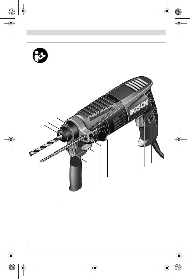
Abgebildete Komponenten
Die Nummerierung der abgebildeten Komponenten bezieht sich auf die Darstellung des Elektrowerkzeuges auf der Grafikseite.
1Werkzeugaufnahme SDS-plus
2Staubschutzkappe
3Verriegelungshülse
4Feststelltaste für Ein-/Ausschalter
5Ein-/Ausschalter
6Drehrichtungsumschalter (GBH 2-18 RE)
7Umschalter „Bohren/Hammerbohren“
8Taste für Tiefenanschlageinstellung
9Flügelschraube für Zusatzgriffverstellung
10Zusatzgriff
11Tiefenanschlag
Deutsch | 9
12Sicherungsschraube für Zahnkranzbohrfutter*
13Zahnkranzbohrfutter*
14SDS-plus-Aufnahmeschaft für Bohrfutter*
15Absaugöffnung Saugfix*
16Klemmschraube Saugfix*
17Tiefenanschlag Saugfix*
18Teleskoprohr Saugfix*
19Flügelschraube Saugfix*
20Führungsrohr Saugfix*
21Universalhalter mit SDS-plus- Aufnahmeschaft*
*Abgebildetes oder beschriebenes Zubehör gehört nicht zum Standard-Lieferumfang. Das vollständige Zubehör finden Sie in unserem Zubehörprogramm.
Technische Daten
Bohrhammer |
|
GBH 2-18 E |
GBH 2-18 RE |
|
|
Professional |
Professional |
Sachnummer |
|
3 611 B58 2.. |
3 611 B58 3.. |
Drehzahlsteuerung |
|
z |
z |
Rechts-/Linkslauf |
|
– |
z |
Nennaufnahmeleistung |
W |
550 |
550 |
Schlagzahl bei Nenndrehzahl |
min-1 |
0–3960 |
0–3960 |
Einzelschlagstärke |
J |
0–1,7 |
0–1,7 |
Nenndrehzahl |
min-1 |
|
|
– Rechtslauf |
450–1550 |
450–1550 |
|
– Linkslauf |
min-1 |
– |
450–930 |
Werkzeugaufnahme |
|
SDS-plus |
SDS-plus |
Durchmesser Spindelhals |
mm |
43 (Euro-Norm) |
43 (Euro-Norm) |
Bohrdurchmesser max.: |
|
|
|
– Beton |
mm |
18 |
18 |
– Stahl |
mm |
13 |
13 |
– Holz |
mm |
30 |
30 |
Gewicht entsprechend EPTA-Procedure 01/2003 |
kg |
2,0 |
2,0 |
Schutzklasse |
|
/ II |
/ II |
|
|
|
|
Angaben gelten für Nennspannungen [U] 230/240 V. Bei niedrigeren Spannungen und in länderspezifischen Ausführungen können diese Angaben variieren.
Bitte beachten Sie die Sachnummer auf dem Typenschild Ihres Elektrowerkzeugs. Die Handelsbezeichnungen einzelner Elektrowerkzeuge können variieren.
|
|
Bosch Power Tools |
|
|
1 619 P07 179 | (17.3.09) |
|
|
||
|
|
|
|
|
|
|
|
|
|
|
|
|
|
|
|
|
|
|
|
|
|
|
|
|
|
|
|
|
|
OBJ_BUCH-427-002.book Page 10 Tuesday, March 17, 2009 6:40 PM
10 | Deutsch
Geräusch-/Vibrationsinformation
Messwerte ermittelt entsprechend EN 60745.
Der A-bewertete Geräuschpegel des Elektrowerkzeugs beträgt typischerweise: Schalldruckpegel 88 dB(A); Schallleistungspegel 99 dB(A). Unsicherheit K=3 dB.
Gehörschutz tragen!
Schwingungsgesamtwerte (Vektorsumme dreier Richtungen) ermittelt entsprechend EN 60745: Hammerbohren in Beton: Schwingungsemissionswert ah =15 m/s2, Unsicherheit K=1,5 m/s2,
Bohren in Metall: Schwingungsemissionswert ah <2,5 m/s2, Unsicherheit K=1,5 m/s2, Schrauben: Schwingungsemissionswert
ah <2,5 m/s2, Unsicherheit K=1,5 m/s2.
Der in diesen Anweisungen angegebene Schwingungspegel ist entsprechend einem in EN 60745 genormten Messverfahren gemessen worden und kann für den Vergleich von Elektrowerkzeugen miteinander verwendet werden. Er eignet sich auch für eine vorläufige Einschätzung der Schwingungsbelastung.
Der angegebene Schwingungspegel repräsentiert die hauptsächlichen Anwendungen des Elektrowerkzeugs. Wenn allerdings das Elektrowerkzeug für andere Anwendungen, mit abweichenden Einsatzwerkzeugen oder ungenügender Wartung eingesetzt wird, kann der Schwingungspegel abweichen. Dies kann die Schwingungsbelastung über den gesamten Arbeitszeitraum deutlich erhöhen.
Für eine genaue Abschätzung der Schwingungsbelastung sollten auch die Zeiten berücksichtigt werden, in denen das Gerät abgeschaltet ist oder zwar läuft, aber nicht tatsächlich im Einsatz ist. Dies kann die Schwingungsbelastung über den gesamten Arbeitszeitraum deutlich reduzieren.
Legen Sie zusätzliche Sicherheitsmaßnahmen zum Schutz des Bedieners vor der Wirkung von Schwingungen fest wie zum Beispiel: Wartung von Elektrowerkzeug und Einsatzwerkzeugen, Warmhalten der Hände, Organisation der Arbeitsabläufe.
Konformitätserklärung
Wir erklären in alleiniger Verantwortung, dass das unter „Technische Daten“ beschriebene Produkt mit den folgenden Normen oder normativen Dokumenten übereinstimmt: EN 60745 gemäß den Bestimmungen der Richtlinien 2004/108/EG, 98/37/EG (bis 28.12.2009), 2006/42/EG (ab 29.12.2009).
Technische Unterlagen bei: Robert Bosch GmbH, PT/ESC, D-70745 Leinfelden-Echterdingen
Dr. Egbert Schneider |
Dr. Eckerhard Strötgen |
Senior Vice President |
Head of Product |
Engineering |
Certification |
Robert Bosch GmbH, Power Tools Division
D-70745 Leinfelden-Echterdingen
Leinfelden, 23.07.2007
Montage
fZiehen Sie vor allen Arbeiten am Elektrowerkzeug den Netzstecker aus der Steckdose.
Zusatzgriff
fVerwenden Sie Ihr Elektrowerkzeug nur mit dem Zusatzgriff 10.
Zusatzgriff schwenken (siehe Bild A)
Sie können den Zusatzgriff 10 beliebig schwenken, um eine sichere und ermüdungsarme Arbeitshaltung zu erreichen.
Drehen Sie die Flügelschraube für die Zusatzgriffverstellung 9 entgegen dem Uhrzeigersinn und schwenken Sie den Zusatzgriff 10 in die gewünschte Position. Danach drehen Sie die Flügelschraube 9 im Uhrzeigersinn wieder fest.
Bohrtiefe einstellen (siehe Bild B)
Mit dem Tiefenanschlag 11 kann die gewünschte Bohrtiefe X festgelegt werden.
Drücken Sie die Taste für die Tiefenanschlageinstellung 8 und setzen Sie den Tiefenanschlag in den Zusatzgriff 10 ein.
|
|
1 619 P07 179 | (17.3.09) |
|
|
Bosch Power Tools |
|
|
||
|
|
|
|
|
|
|
|
|
|
|
|
|
|
|
|
|
|
|
|
|
|
|
|
|
|
|
|
|
|
OBJ_BUCH-427-002.book Page 11 Tuesday, March 17, 2009 6:40 PM
Die Riffelung am Tiefenanschlag 11 muss nach unten zeigen.
Schieben Sie das SDS-plus-Einsatzwerkzeug bis zum Anschlag in die Werkzeugaufnahme SDSplus 1. Die Beweglichkeit des SDS-plus-Werk- zeugs kann sonst zu einer falschen Einstellung der Bohrtiefe führen.
Ziehen Sie den Tiefenanschlag so weit heraus, dass der Abstand zwischen der Spitze des Bohrers und der Spitze des Tiefenanschlags der gewünschten Bohrtiefe X entspricht.
Bohrfutter und Werkzeuge auswählen
Zum Hammerbohren benötigen Sie SDS-plus- Werkzeuge, die in das SDS-plus-Bohrfutter eingesetzt werden.
Zum Bohren ohne Schlag in Holz, Metall, Keramik und Kunststoff sowie zum Schrauben werden Werkzeuge ohne SDS-plus (z.B. Bohrer mit zylindrischem Schaft) verwendet. Für diese Werkzeuge benötigen Sie ein Schnellspannbohrfutter bzw. Zahnkranzbohrfutter.
Zahnkranzbohrfutter wechseln
Um mit Werkzeugen ohne SDS-plus (z.B. Bohrer mit zylindrischem Schaft) arbeiten zu können, müssen Sie ein geeignetes Bohrfutter montieren (Zahnkranzoder Schnellspannbohrfutter, Zubehör).
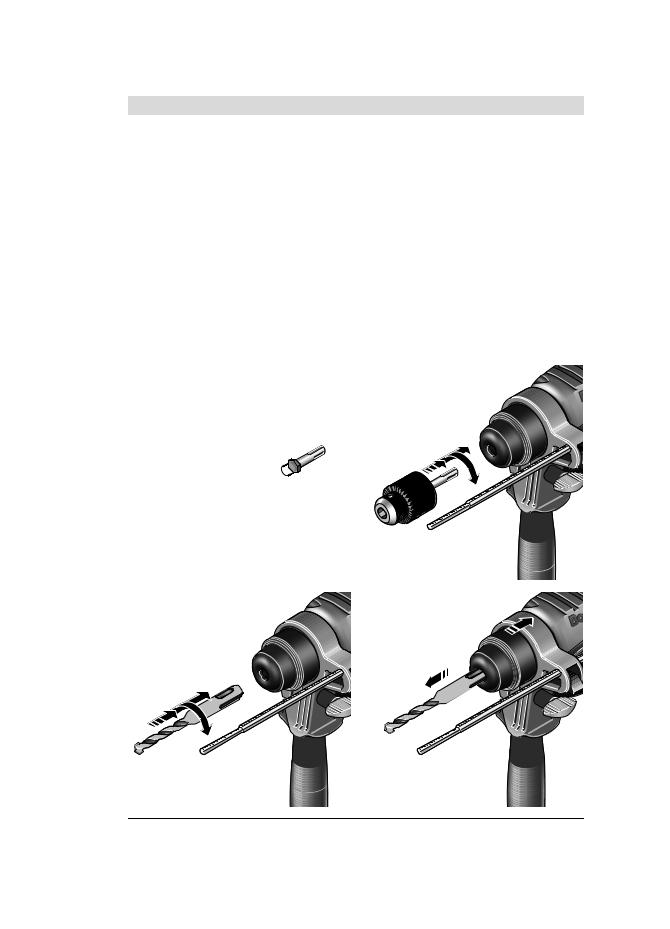
Zahnkranzbohrfutter montieren (siehe Bild C)
Schrauben Sie den SDS-plus-Aufnahmeschaft 14 in ein Zahnkranzbohrfutter 13. Sichern Sie das Zahnkranzbohrfutter 13 mit der Sicherungsschraube 12. Beachten Sie, dass die Sicherungsschraube ein Linksgewinde hat.
Zahnkranzbohrfutter einsetzen (siehe Bild D)
Reinigen Sie das Einsteckende des Aufnahmeschaftes und fetten Sie es leicht ein.
Setzen Sie das Zahnkranzbohrfutter mit dem Aufnahmeschaft drehend in die Werkzeugaufnahme ein, bis es selbsttätig verriegelt wird.
Prüfen Sie die Verriegelung durch Ziehen am Zahnkranzbohrfutter.
Zahnkranzbohrfutter entnehmen
Schieben Sie die Verriegelungshülse 3 nach hinten und nehmen Sie das Zahnkranzbohrfutter 13 ab.
Deutsch | 11
Werkzeugwechsel
Die Staubschutzkappe 2 verhindert weitgehend das Eindringen von Bohrstaub in die Werkzeugaufnahme während des Betriebes. Achten Sie beim Einsetzen des Werkzeuges darauf, dass die Staubschutzkappe 2 nicht beschädigt wird.
fEine beschädigte Staubschutzkappe ist sofort zu ersetzen. Es wird empfohlen, dies von einem Kundendienst vornehmen zu lassen.
SDS-plus-Einsatzwerkzeug einsetzen (siehe Bild E)
Mit dem SDS-plus-Bohrfutter können Sie das Einsatzwerkzeug einfach und bequem ohne Verwendung zusätzlicher Werkzeuge wechseln.
Reinigen Sie das Einsteckende des Einsatzwerkzeuges und fetten Sie es leicht ein.
Setzen Sie das Einsatzwerkzeug drehend in die Werkzeugaufnahme ein, bis es selbsttätig verriegelt wird.
Überprüfen Sie die Verriegelung durch Ziehen am Werkzeug.
Das SDS-plus-Einsatzwerkzeug ist systembedingt frei beweglich. Dadurch entsteht beim Leerlauf eine Rundlaufabweichung. Dies hat keine Auswirkungen auf die Genauigkeit des Bohrlochs, da sich der Bohrer beim Bohren selbst zentriert.
SDS-plus-Einsatzwerkzeug entnehmen (siehe Bild F)
Schieben Sie die Verriegelungshülse 3 nach hinten und entnehmen Sie das Einsatzwerkzeug.
Einsatzwerkzeuge ohne SDS-plus einsetzen
Hinweis: Verwenden Sie Werkzeuge ohne SDSplus nicht zum Hammerbohren! Werkzeuge ohne SDS-plus und ihr Bohrfutter werden beim Hammerbohren beschädigt.
Setzen Sie ein Zahnkranzbohrfutter 13 ein (siehe „Zahnkranzbohrfutter wechseln“, Seite 11).
Öffnen Sie das Zahnkranzbohrfutter 13 durch Drehen, bis das Werkzeug eingesetzt werden kann. Setzen Sie das Werkzeug ein.
|
|
Bosch Power Tools |
|
|
1 619 P07 179 | (17.3.09) |
|
|
||
|
|
|
|
|
|
|
|
|
|
|
|
|
|
|
|
|
|
|
|
|
|
|
|
|
|
|
|
|
|
OBJ_BUCH-427-002.book Page 12 Tuesday, March 17, 2009 6:40 PM
12 | Deutsch
Stecken Sie den Bohrfutterschlüssel in die entsprechenden Bohrungen des Zahnkranzbohrfutters 13 und spannen Sie das Werkzeug gleichmäßig fest.
Stellen Sie den Umschalter 7 auf das Symbol „Bohren“.
Einsatzwerkzeuge ohne SDS-plus entnehmen
Drehen Sie die Hülse des Zahnkranzbohrfutters 13 mit Hilfe des Bohrfutterschlüssels entgegen dem Uhrzeigersinn, bis das Einsatzwerkzeug entnommen werden kann.
Staubabsaugung mit Saugfix (Zubehör)
fStäube von Materialien wie bleihaltigem Anstrich, einigen Holzarten, Mineralien und Metall können gesundheitsschädlich sein. Berühren oder Einatmen der Stäube können allergische Reaktionen und/oder Atemwegserkrankungen des Benutzers oder in der Nähe befindlicher Personen hervorrufen. Bestimmte Stäube wie Eichenoder Buchenstaub gelten als krebserzeugend, besonders in Verbindung mit Zusatzstoffen zur Holzbehandlung (Chromat, Holzschutzmittel). Asbesthaltiges Material darf nur von Fachleuten bearbeitet werden.
–Benutzen Sie möglichst eine Staubabsaugung.
–Sorgen Sie für gute Belüftung des Arbeitsplatzes.
–Es wird empfohlen, eine Atemschutzmaske mit Filterklasse P2 zu tragen.
Beachten Sie in Ihrem Land gültige Vorschriften für die zu bearbeitenden Materialien.
Saugfix montieren (siehe Bild G)
Für die Staubabsaugung wird ein Saugfix (Zubehör) benötigt. Beim Bohren federt der Saugfix zurück, sodass der Saugfix-Kopf immer dicht am Untergrund gehalten wird.
Drücken Sie die Taste für die Tiefenanschlageinstellung 8 und entnehmen Sie den Tiefenanschlag 11. Drücken Sie die Taste 8 erneut und setzen Sie den Saugfix von vorn in den Zusatzgriff 10 ein.
Schließen Sie einen Absaugschlauch (Durchmesser 19 mm, Zubehör) an die Absaugöffnung 15 des Saugfix an.
Der Staubsauger muss für den zu bearbeitenden Werkstoff geeignet sein.
Verwenden Sie beim Absaugen von besonders gesundheitsgefährdenden, krebserzeugenden oder trockenen Stäuben einen Spezialsauger.
In Deutschland werden für Holzstäube auf Grund TRGS 553 geprüfte Absaugeinrichtungen gefordert, die Eigenabsaugung darf im gewerblichen Bereich nicht verwendet werden. Für andere Materialien muss der gewerbliche Betreiber die speziellen Anforderungen mit der zuständigen Berufsgenossenschaft klären.
Bohrtiefe am Saugfix einstellen (siehe Bild H)
Sie können die gewünschte Bohrtiefe X auch bei montiertem Saugfix festlegen.
Schieben Sie das SDS-plus-Einsatzwerkzeug bis zum Anschlag in die Werkzeugaufnahme SDSplus 1. Die Beweglichkeit des SDS-plus-Werk- zeugs kann sonst zu einer falschen Einstellung der Bohrtiefe führen.
Lösen Sie die Flügelschraube 19 am Saugfix.
Setzen Sie das Elektrowerkzeug ohne es einzuschalten fest auf die zu bohrende Stelle auf. Das SDS-plus-Einsatzwerkzeug muss dabei auf der Fläche aufsetzen.
Verschieben Sie das Führungsrohr 20 des Saugfix so in seiner Halterung, dass der Saugfix-Kopf auf der zu bohrenden Fläche aufliegt. Schieben Sie das Führungsrohr 20 nicht weiter über das Teleskoprohr 18 als nötig, sodass ein möglichst großer Teil der Skala auf dem Teleskoprohr 18 sichtbar bleibt.
Ziehen Sie die Flügelschraube 19 wieder fest. Lösen Sie die Klemmschraube 16 am Tiefenanschlag des Saugfix.
Verschieben Sie den Tiefenanschlag 17 so auf dem Teleskoprohr 18, dass der im Bild gezeigte Abstand X Ihrer gewünschten Bohrtiefe entspricht.
Ziehen Sie die Klemmschraube 16 in dieser Position fest.
|
|
1 619 P07 179 | (17.3.09) |
|
|
Bosch Power Tools |
|
|
||
|
|
|
|
|
|
|
|
|
|
|
|
|
|
|
|
|
|
|
|
|
|
|
|
|
|
|
|
|
|
OBJ_BUCH-427-002.book Page 13 Tuesday, March 17, 2009 6:40 PM
Betrieb
Inbetriebnahme
fBeachten Sie die Netzspannung! Die Spannung der Stromquelle muss mit den Angaben auf dem Typenschild des Elektrowerkzeuges übereinstimmen. Mit 230 V gekennzeichnete Elektrowerkzeuge können auch an 220 V betrieben werden.
Betriebsart einstellen
Mit dem Umschalter „Bohren/Hammerbohren“ 7 wählen Sie die Betriebsart des Elektrowerkzeugs.
Hinweis: Ändern Sie die Betriebsart nur bei ausgeschaltetem Elektrowerkzeug! Das Elektrowerkzeug kann sonst beschädigt werden.
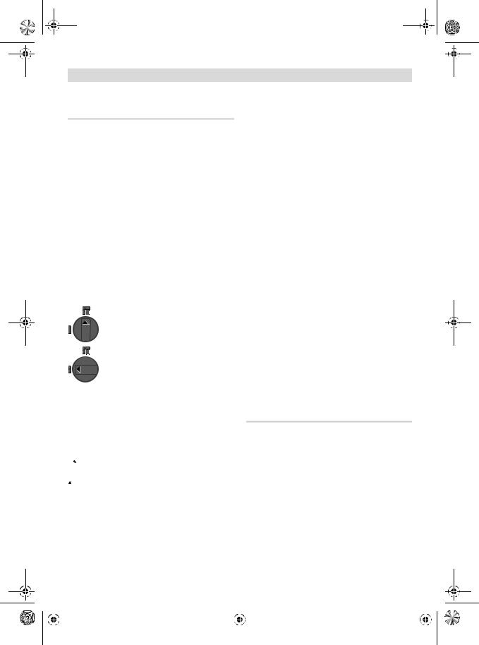
Drehen Sie zum Wechsel der Betriebsart den Umschalter „Bohren/Hammerbohren“ 7 in die gewünschte Position.
Position zum Hammerbohren in
Beton oder Stein
Position zum Bohren ohne Schlag in Holz, Metall, Keramik und Kunststoff sowie zum Schrauben
Drehrichtung einstellen (GBH 2-18 RE) (siehe Bild I)
Mit dem Drehrichtungsumschalter 6 können Sie die Drehrichtung des Elektrowerkzeuges ändern. Bei gedrücktem Ein-/Ausschalter 5 ist dies jedoch nicht möglich.
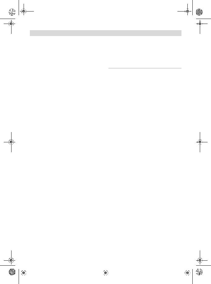
 Rechtslauf: Drücken Sie den Drehrichtungsumschalter 6 bis zum Anschlag nach rechts.
 Linkslauf: Drücken Sie den Drehrichtungsumschalter 6 bis zum Anschlag nach links.
Stellen Sie die Drehrichtung zum Hammerbohren und Bohren immer auf Rechtslauf.
Deutsch | 13
Ein-/Ausschalten
Zum Einschalten des Elektrowerkzeugs drücken Sie den Ein-/Ausschalter 5.
Zum Arretieren des Ein-/Ausschalters halten Sie diesen gedrückt und drücken zusätzlich die Feststelltaste 4.
Zum Ausschalten des Elektrowerkzeugs lassen Sie den Ein-/Ausschalter 5 los. Bei arretiertem Ein-/Ausschalter 5 drücken Sie diesen zuerst und lassen ihn danach los.
Drehzahl/Schlagzahl einstellen
Sie können die Drehzahl/Schlagzahl des eingeschalteten Elektrowerkzeugs stufenlos regulieren, je nachdem, wie weit Sie den Ein-/Aus- schalter 5 eindrücken.
Leichter Druck auf den Ein-/Ausschalter 5 bewirkt eine niedrige Drehzahl/Schlagzahl. Mit zunehmendem Druck erhöht sich die Drehzahl/ Schlagzahl.
Überlastkupplung
fKlemmt oder hakt das Einsatzwerkzeug, wird der Antrieb zur Bohrspindel unterbrochen. Halten Sie, wegen der dabei auftretenden Kräfte, das Elektrowerkzeug immer mit beiden Händen gut fest und nehmen Sie einen festen Stand ein.
fSchalten Sie das Elektrowerkzeug aus und lösen Sie das Einsatzwerkzeug, wenn das Elektrowerkzeug blockiert. Beim Einschalten mit einem blockierten Bohrwerkzeug entstehen hohe Reaktionsmomente.
Arbeitshinweise
Schrauberbits einsetzen (siehe Bild J)
fSetzen Sie das Elektrowerkzeug nur ausgeschaltet auf die Mutter/Schraube auf.
Sich drehende Einsatzwerkzeuge können abrutschen.
Zur Verwendung von Schrauberbits benötigen Sie einen Universalhalter 21 mit SDS-plus-Auf- nahmeschaft (Zubehör).
Reinigen Sie das Einsteckende des Aufnahmeschaftes und fetten Sie es leicht ein.
Setzen Sie den Universalhalter drehend in die Werkzeugaufnahme ein, bis er selbsttätig verriegelt wird.
|
|
Bosch Power Tools |
|
|
1 619 P07 179 | (17.3.09) |
|
|
||
|
|
|
|
|
|
|
|
|
|
|
|
|
|
|
|
|
|
|
|
|
|
|
|
|
|
|
|
|
|
 OBJ_BUCH-427-002.book Page 14 Tuesday, March 17, 2009 6:40 PM
14 | Deutsch
Prüfen Sie die Verriegelung durch Ziehen am Universalhalter.
Setzen Sie einen Schrauberbit in den Universalhalter. Verwenden Sie nur zum Schraubenkopf passende Schrauberbits.
Zum Entnehmen des Universalhalters schieben Sie die Verriegelungshülse 3 nach hinten und entnehmen den Universalhalter 21 aus der Werkzeugaufnahme.
Wartung und Service
Wartung und Reinigung
fZiehen Sie vor allen Arbeiten am Elektrowerkzeug den Netzstecker aus der Steckdose.
fHalten Sie das Elektrowerkzeug und die Lüftungsschlitze sauber, um gut und sicher zu arbeiten.
fEine beschädigte Staubschutzkappe ist sofort zu ersetzen. Es wird empfohlen, dies von einem Kundendienst vornehmen zu lassen.
Säubern Sie die Werkzeugaufnahme 1 nach jedem Gebrauch.
Sollte das Elektrowerkzeug trotz sorgfältiger Herstellungsund Prüfverfahren einmal ausfallen, ist die Reparatur von einer autorisierten Kundendienststelle für Bosch-Elektrowerkzeuge ausführen zu lassen.
Geben Sie bei allen Rückfragen und Ersatzteilbestellungen bitte unbedingt die 10-stellige Sachnummer laut Typenschild des Elektrowerkzeuges an.
Kundendienst und Kundenberatung
Der Kundendienst beantwortet Ihre Fragen zu Reparatur und Wartung Ihres Produkts sowie zu Ersatzteilen. Explosionszeichnungen und Informationen zu Ersatzteilen finden Sie auch unter: www.bosch-pt.com
Das Bosch-Kundenberater-Team hilft Ihnen gerne bei Fragen zu Kauf, Anwendung und Einstellung von Produkten und Zubehören.
www.powertool-portal.de, das Internetportal für Handwerker und Heimwerker. www.ewbc.de, der Informations-Pool für Handwerk und Ausbildung.
Deutschland
Robert Bosch GmbH Servicezentrum Elektrowerkzeuge Zur Luhne 2
37589 Kalefeld – Willershausen
Tel. Kundendienst: +49 (1805) 70 74 10 Fax: +49 (1805) 70 74 11
E-Mail: Servicezentrum.Elektrowerkzeuge@de.bosch.com Tel. Kundenberatung: +49 (1803) 33 57 99 Fax: +49 (711) 7 58 19 30
E-Mail: kundenberatung.ew@de.bosch.com
Österreich
Tel.: +43 (01) 7 97 22 20 10
Fax: +43 (01) 7 97 22 20 11
E-Mail: service.elektrowerkzeuge@at.bosch.com
Schweiz
Tel.: +41 (044) 8 47 15 11
Fax: +41 (044) 8 47 15 51
Luxemburg
Tel.: +32 (070) 22 55 65
Fax: +32 (070) 22 55 75
E-Mail: outillage.gereedschap@be.bosch.com
Entsorgung
Elektrowerkzeuge, Zubehör und Verpackungen sollen einer umweltgerechten Wiederverwertung zugeführt werden.
Nur für EU-Länder:
Werfen Sie Elektrowerkzeuge nicht in den Hausmüll!
Gemäß der Europäischen Richtlinie 2002/96/EG über Elektro-
und Elektronik-Altgeräte und ihrer Umsetzung in nationales Recht
müssen nicht mehr gebrauchsfähige Elektrowerkzeuge getrennt gesammelt und einer umweltgerechten Wiederverwertung zugeführt werden.
Änderungen vorbehalten.
|
|
1 619 P07 179 | (17.3.09) |
|
|
Bosch Power Tools |
|
|
||
|
|
|
|
|
|
|
|
|
|
|
|
|
|
|
|
|
|
|
|
|
|
|
|
|
|
|
|
|
|

OBJ_BUCH-427-002.book Page 15 Tuesday, March 17, 2009 6:40 PM
Safety Notes
General Power Tool Safety Warnings
|
Read all safety warnings and all |
WARNING |
|
|
instructions. Failure to follow |
the warnings and instructions may result in electric shock, fire and/or serious injury.
Save all warnings and instructions for future reference.
The term “power tool” in the warnings refers to your mains-operated (corded) power tool or battery-operated (cordless) power tool.
1)Work area safety
a)Keep work area clean and well lit. Cluttered or dark areas invite accidents.
b)Do not operate power tools in explosive atmospheres, such as in the presence of flammable liquids, gases or dust. Power tools create sparks which may ignite the dust or fumes.
c)Keep children and bystanders away while operating a power tool. Distractions can cause you to lose control.
2)Electrical safety
a)Power tool plugs must match the outlet. Never modify the plug in any way. Do not use any adapter plugs with earthed (grounded) power tools. Unmodified plugs and matching outlets will reduce risk of electric shock.
b)Avoid body contact with earthed or grounded surfaces, such as pipes, radiators, ranges and refrigerators. There is an increased risk of electric shock if your body is earthed or grounded.
c)Do not expose power tools to rain or wet conditions. Water entering a power tool will increase the risk of electric shock.
d)Do not abuse the cord. Never use the cord for carrying, pulling or unplugging the power tool. Keep cord away from heat, oil, sharp edges and moving parts.
Damaged or entangled cords increase the risk of electric shock.
English | 15
e)When operating a power tool outdoors, use an extension cord suitable for outdoor use. Use of a cord suitable for outdoor use reduces the risk of electric shock.
f)If operating a power tool in a damp location is unavoidable, use a residual current device (RCD) protected supply. Use of an RCD reduces the risk of electric shock.
3)Personal safety
a)Stay alert, watch what you are doing and use common sense when operating a power tool. Do not use a power tool while you are tired or under the influence of drugs, alcohol or medication. A moment of inattention while operating power tools may result in serious personal injury.
b)Use personal protective equipment. Always wear eye protection. Protective equipment such as dust mask, non-skid safety shoes, hard hat, or hearing protection used for appropriate conditions will reduce personal injuries.
c)Prevent unintentional starting. Ensure the switch is in the off-position before connecting to power source and/or battery pack, picking up or carrying the tool.
Carrying power tools with your finger on the switch or energising power tools that have the switch on invites accidents.
d)Remove any adjusting key or wrench before turning the power tool on. A wrench or a key left attached to a rotating part of the power tool may result in personal injury.
e)Do not overreach. Keep proper footing and balance at all times. This enables better control of the power tool in unexpected situations.
f)Dress properly. Do not wear loose clothing or jewellery. Keep your hair, clothing and gloves away from moving parts.
Loose clothes, jewellery or long hair can be caught in moving parts.
g)If devices are provided for the connection of dust extraction and collection facilities, ensure these are connected and properly used. Use of dust collection can reduce dust-related hazards.
|
|
Bosch Power Tools |
|
|
1 619 P07 179 | (17.3.09) |
|
|
||
|
|
|
|
|
|
|
|
|
|
|
|
|
|
|
|
|
|
|
|
|
|
|
|
|
|
|
|
|
|
OBJ_BUCH-427-002.book Page 16 Tuesday, March 17, 2009 6:40 PM
16 | English
4)Power tool use and care
a)Do not force the power tool. Use the correct power tool for your application. The correct power tool will do the job better and safer at the rate for which it was designed.
b)Do not use the power tool if the switch does not turn it on and off. Any power tool that cannot be controlled with the switch is dangerous and must be repaired.
c)Disconnect the plug from the power source and/or the battery pack from the power tool before making any adjustments, changing accessories, or storing power tools. Such preventive safety measures reduce the risk of starting the power tool accidentally.
d)Store idle power tools out of the reach of children and do not allow persons unfamiliar with the power tool or these instructions to operate the power tool.
Power tools are dangerous in the hands of untrained users.
e)Maintain power tools. Check for misalignment or binding of moving parts, breakage of parts and any other condition that may affect the power tool’s operation. If damaged, have the power tool repaired before use. Many accidents are caused by poorly maintained power tools.
f)Keep cutting tools sharp and clean. Properly maintained cutting tools with sharp cutting edges are less likely to bind and are easier to control.
g)Use the power tool, accessories and tool bits etc. in accordance with these instructions, taking into account the working conditions and the work to be performed. Use of the power tool for operations different from those intended could result in a hazardous situation.
5)Service
a)Have your power tool serviced by a qualified repair person using only identical replacement parts. This will ensure that the safety of the power tool is maintained.
Hammer Safety Warnings
fWear ear protectors. Exposure to noise can cause hearing loss.
fUse auxiliary handle(s), if supplied with the tool. Loss of control can cause personal injury.
fHold power tool by insulated gripping surfaces, when performing an operation where the cutting accessory may contact hidden wiring or its own cord. Cutting accessory contacting a “live” wire may make exposed metal parts of the power tool “live” and could give the operator an electric shock.
fUse suitable detectors to determine if utility lines are hidden in the work area or call the local utility company for assistance.
Contact with electric lines can lead to fire and electric shock. Damaging a gas line can lead to explosion. Penetrating a water line causes property damage or may cause an electric shock.
fWhen working with the machine, always hold it firmly with both hands and provide for a secure stance. The power tool is guided more secure with both hands.
fSecure the workpiece. A workpiece clamped with clamping devices or in a vice is held more secure than by hand.
fKeep your workplace clean. Blends of materials are particularly dangerous. Dust from light alloys can burn or explode.
fAlways wait until the machine has come to a complete stop before placing it down. The tool insert can jam and lead to loss of control over the power tool.
fNever use the machine with a damaged cable. Do not touch the damaged cable and pull the mains plug when the cable is damaged while working. Damaged cables increase the risk of an electric shock.
|
|
1 619 P07 179 | (17.3.09) |
|
|
Bosch Power Tools |
|
|
||
|
|
|
|
|
|
|
|
|
|
|
|
|
|
|
|
|
|
|
|
|
|
|
|
|
|
|
|
|
|

OBJ_BUCH-427-002.book Page 17 Tuesday, March 17, 2009 6:40 PM
fProducts sold in GB only: Your product is fitted with an BS 1363/A approved electric plug with internal fuse (ASTA approved to BS 1362).
If the plug is not suitable for your socket outlets, it should be cut off and an appropriate plug fitted in its place by an authorised customer service agent. The replacement plug should have the same fuse rating as the original plug.
The severed plug must be disposed of to avoid a possible shock hazard and should never be
inserted into a mains socket elsewhere.
Products sold in AUS and NZ only: Use a residual current device (RCD) with a rated residual current of 30 mA or less.
Functional Description
Read all safety warnings and all instructions. Failure to follow the
warnings and instructions may re-
sult in electric shock, fire and/or serious injury.
While reading the operating instructions, unfold the graphics page for the machine and leave it open.
Intended Use
The machine is intended for hammer drilling in concrete, brick and stone. It is also suitable for drilling without impact in wood, metal, ceramic and plastic. Machines with electronic control and right/left rotation are also suitable for screwdriving.
English | 17
Product Features
The numbering of the product features refers to the illustration of the machine on the graphics page.
1SDS-plus tool holder
2Dust protection cap
3Locking sleeve
4Lock-on button for On/Off switch
5On/Off switch
6Rotational direction switch (GBH 2-18 RE)
7Selector switch for drilling/hammer drilling
8Button for depth stop adjustment
9Wing bolt for adjustment of auxiliary handle
10Auxiliary handle
11Depth stop
12Securing screw for key type drill chuck*
13Key type drill chuck*
14SDS-plus adapter shank for drill chuck*
15Extraction sleeve of the dust extraction attachment*
16Clamping screw for the dust extraction attachment*
17Depth stop of the dust extraction attachment*
18Telescopic pipe of the dust extraction attachment*
19Wing bolt of the dust extraction attachment*
20Guide pipe of the dust extraction attachment*
21Universal bit holder with SDS-plus shank*
*Accessories shown or described are not part of the standard delivery scope of the product. A complete overview of accessories can be found in our accessories program.
|
|
Bosch Power Tools |
|
|
1 619 P07 179 | (17.3.09) |
|
|
||
|
|
|
|
|
|
|
|
|
|
|
|
|
|
|
|
|
|
|
|
|
|
|
|
|
|
|
|
|
|

OBJ_BUCH-427-002.book Page 18 Tuesday, March 17, 2009 6:40 PM
18 | English
Technical Data
Rotary Hammer |
|
GBH 2-18 E |
GBH 2-18 RE |
|
|
Professional |
Professional |
Article number |
|
3 611 B58 2.. |
3 611 B58 3.. |
Speed control |
|
z |
z |
Right/left rotation |
|
– |
z |
Rated power input |
W |
550 |
550 |
Impact frequency at rated speed |
min-1 |
0–3960 |
0–3960 |
Impact energy per stroke |
J |
0–1.7 |
0–1.7 |
Rated speed |
min-1 |
|
|
– Right rotation |
450–1550 |
450–1550 |
|
– Left rotation |
min-1 |
– |
450–930 |
Tool holder |
|
SDS-plus |
SDS-plus |
Spindle collar diameter |
mm |
43 (Euro-Norm) |
43 (Euro-Norm) |
Drilling diameter, max.: |
|
|
|
– Concrete |
mm |
18 |
18 |
– Steel |
mm |
13 |
13 |
– Wood |
mm |
30 |
30 |
Weight according to EPTA-Procedure 01/2003 |
kg |
2.0 |
2.0 |
Protection class |
|
/ II |
/ II |
|
|
|
|
The values given are valid for nominal voltages [U] of 230/240 V. For lower voltage and models for specific countries, these values can vary.
Please observe the article number on the type plate of your machine. The trade names of the individual machines may vary.
Noise/Vibration Information
Measured values determined according to EN 60745.
Typically the A-weighted noise levels of the product are: Sound pressure level 88 dB(A); Sound power level 99 dB(A). Uncertainty
K =3 dB.
Wear hearing protection!
Vibration total values (triax vector sum) determined according to EN 60745:
Hammer drilling into concrete: Vibrational emission value ah =15 m/s2, uncertainty K=1.5 m/s2, Drilling in metal: Vibrational emission value
ah <2.5 m/s2, uncertainty K=1.5 m/s2, Screwdriving without impact: Vibrational emission value ah <2.5 m/s2, uncertainty K=1.5 m/s2.
The vibration emission level given in this information sheet has been measured in accordance with a standardised test given in EN 60745 and may be used to compare one tool with another. It may be used for a preliminary assessment of exposure.
The declared vibration emission level represents the main applications of the tool. However if the tool is used for different applications, with different accessories or poorly maintained, the vibration emission may differ. This may significantly increase the exposure level over the total working period.
|
|
1 619 P07 179 | (17.3.09) |
|
|
Bosch Power Tools |
|
|
||
|
|
|
|
|
|
|
|
|
|
|
|
|
|
|
|
|
|
|
|
|
|
|
|
|
|
|
|
|
|
OBJ_BUCH-427-002.book Page 19 Tuesday, March 17, 2009 6:40 PM
An estimation of the level of exposure to vibration should also take into account the times when the tool is switched off or when it is running but not actually doing the job. This may significantly reduce the exposure level over the total working period.
Identify additional safety measures to protect the operator from the effects of vibration such as: maintain the tool and the accessories, keep the hands warm, organisation of work patterns.
Declaration of Conformity
We declare under our sole responsibility that the product described under “Technical Data” is in conformity with the following standards or standardization documents: EN 60745 according to the provisions of the directives 2004/108/EC, 98/37/EC (until 28 Dec 2009), 2006/42/EC (from 29 Dec 2009).
Technical file at:
Robert Bosch GmbH, PT/ESC, D-70745 Leinfelden-Echterdingen
Dr. Egbert Schneider |
Dr. Eckerhard Strötgen |
Senior Vice President |
Head of Product |
Engineering |
Certification |
Robert Bosch GmbH, Power Tools Division
D-70745 Leinfelden-Echterdingen
Leinfelden, 23.07.2007
English | 19
Assembly
fBefore any work on the machine itself, pull the mains plug.
Auxiliary Handle
fOperate your machine only with the auxiliary handle 10.
Rotating the Auxiliary Handle (see figure A)
The auxiliary handle 10 can be set to any position for a secure and low-fatigue working posture.
Turn the wing bolt for adjustment of the auxiliary handle 9 in anticlockwise direction and set the auxiliary handle 10 to the required position. Then tighten the wing bolt 9 again in clockwise direction.
Adjusting the Drilling Depth (see figure B)
The required drilling depth X can be set with the depth stop 11.
Press the button for the depth stop adjustment 8 and insert the depth stop into the auxiliary handle 10.
The knurled surface of the depth stop 11 must face downward.
Insert the SDS-plus drilling tool to the stop into the SDS-plus tool holder 1. Otherwise, the movability of the SDS-plus drilling tool can lead to incorrect adjustment of the drilling depth.
Pull out the depth stop until the distance between the tip of the drill bit and the tip of the depth stop correspond with the desired drilling depth X.
|
|
Bosch Power Tools |
|
|
1 619 P07 179 | (17.3.09) |
|
|
||
|
|
|
|
|
|
|
|
|
|
|
|
|
|
|
|
|
|
|
|
|
|
|
|
|
|
|
|
|
|

OBJ_BUCH-427-002.book Page 20 Tuesday, March 17, 2009 6:40 PM
20 | English
Selecting Drill Chucks and Tools
For hammer drilling, SDS-plus tools are required that are inserted in the SDS-plus drill chuck.
For drilling without impact in wood, metal, ceramic and plastic as well as for screwdriving, tools without SDS-plus are used (e.g., drills with cylindrical shank). For these tools, a keyless chuck or a key type drill chuck are required.
Changing the Key Type Drill Chuck
To work with tools without SDS-plus (e.g., drills with cylindrical shank), a suitable drill chuck must be mounted (key type drill chuck or keyless chuck, accessories).
Mounting the Key Type Drill Chuck (see figure C)
Screw the SDS-plus adapter shank 14 into a key type drill chuck 13. Secure the key type drill chuck 13 with the securing screw 12. Please observe that the securing screw has a left-hand thread.
Inserting the Key Type Drill Chuck (see figure D)
Clean the shank end of the adapter shank and apply a light coat of grease.
Insert the key type drill chuck with the adapter shank into the tool holder with a turning motion until it automatically locks.
Check the locking effect by pulling the key type drill chuck.
Removing the Key Type Drill Chuck
Push the locking sleeve 3 toward the rear and pull out the key type drill chuck 13.
Inserting SDS-plus Drilling Tools (see figure E)
The SDS-plus drill chuck allows for simple and convenient changing of drilling tools without the use of additional tools.
Clean and lightly grease the shank end of the tool.
Insert the tool in a twisting manner into the tool holder until it latches itself.
Check the latching by pulling the tool.
As a requirement of the system, the SDS-plus drilling tool can move freely. This causes a certain radial run-out at no-load, which has no effect on the accuracy of the drill hole, as the drill bit centres itself upon drilling.
Removing SDS-plus Drilling Tools (see figure F)
Push back the locking sleeve 3 and remove the tool.
Inserting Drilling Tools without SDS-plus
Note: Do not use tools without SDS-plus for hammer drilling! Tools without SDS-plus and their drill chucks are damaged by hammer drilling.
Insert a key type drill chuck 13 (see “Changing the Key Type Drill Chuck”, page 20).
Open the key type drill chuck 13 by turning until the tool can be inserted. Insert the tool.
Insert the chuck key into the corresponding holes of the key type drill chuck 13 and clamp the tool uniformly.
Set the selector switch 7 to the “Drilling” symbol.
Removing Drilling Tools without SDS-plus
Turn the sleeve of the key type drill chuck 13 with the drill chuck key in anticlockwise direction until the drilling tool can be removed.
Changing the Tool
The dust protection cap 2 largely prevents the entry of drilling dust into the tool holder during operation. When inserting the tool, take care that the dust protection cap 2 is not damaged.
fA damaged dust protection cap should be changed immediately. We recommend having this carried out by an after-sales service.
Dust Extraction with the Dust Extraction Attachment (Accessory)
fDusts from materials such as lead-containing coatings, some wood types, minerals and metal can be harmful to one’s health. Touching or breathing-in the dusts can cause allergic reactions and/or lead to respiratory infections of the user or bystanders.
|
|
1 619 P07 179 | (17.3.09) |
|
|
Bosch Power Tools |
|
|
||
|
|
|
|
|
|
|
|
|
|
|
|
|
|
|
|
|
|
|
|
|
|
|
|
|
|
|
|
|
|
OBJ_BUCH-427-002.book Page 21 Tuesday, March 17, 2009 6:40 PM
Certain dusts, such as oak or beech dust, are considered as carcinogenic, especially in connection with wood-treatment additives (chromate, wood preservative). Materials containing asbestos may only be worked by specialists.
–Use dust extraction whenever possible.
–Provide for good ventilation of the working place.
–It is recommended to wear a P2 filterclass respirator.
Observe the relevant regulations in your country for the materials to be worked.
Mounting the Dust Extraction Attachment (see figure G)
For dust extraction, the dust extraction attachment (accessory) is required. When drilling, the dust extraction attachment retracts so that the attachment head is always close to the surface at the drill hole.
Press the button for depth stop adjustment 8 and remove the depth stop 11. Press button 8 again and insert the dust extraction attachment into the auxiliary handle 10 from the front.
Connect an extraction hose (diameter 19 mm, accessory) to the extraction sleeve 15 of the dust extraction attachment.
The vacuum cleaner must be suitable for the material being worked.
When vacuuming dry dust that is especially detrimental to health or carcinogenic, use a special vacuum cleaner.
Adjusting the Drilling Depth on the Dust Extraction Attachment (see figure H)
The required drilling depth X can also be adjusted when the dust extraction attachment is mounted.
Insert the SDS-plus drilling tool to the stop into the SDS-plus tool holder 1. Otherwise, the movability of the SDS-plus drilling tool can lead to incorrect adjustment of the drilling depth.
Loosen the wing bolt 19 on the dust extraction attachment.
Without switching the power tool on, apply it firmly to the drilling location. The SDS-plus drilling tool must face against the surface.
English | 21
Position the the guide pipe 20 of the dust extraction attachment in its holding fixture in such a manner that the head of the dust extraction attachment faces against the surface to be drilled. Do not slide the guide pipe 20 further over the telescopic pipe 18 of the dust extraction attachment than required, so that as much as possible of the scale 18 on the telescopic pipe remains visible.
Retighten the wing bolt 19 again. Loosen the clamping screw 16 on the depth stop of the dust extraction attachment.
Move the depth stop 17 on the telescopic pipe 18 in such a manner that the clearance X shown in the figure corresponds with the required drilling depth.
Tighten the clamping screw 16 in this position.
Operation
Starting Operation
fObserve correct mains voltage! The voltage of the power source must agree with the voltage specified on the nameplate of the machine. Power tools marked with 230 V can also be operated with 220 V.
Setting the Operating Mode
With the selector switch for drilling/hammer drilling 7, the operating mode of the machine is selected.
Note: Change the operating mode only when the machine is switched off! Otherwise, the machine can be damaged.
To change the operating mode, turn the selector switch for “drilling/hammer drilling” 7 to the requested position.
Position for hammer drilling in concrete or stone
Position for drilling without impact in wood, metal, ceramic and plastic as well as for screwdriving
|
|
Bosch Power Tools |
|
|
1 619 P07 179 | (17.3.09) |
|
|
||
|
|
|
|
|
|
|
|
|
|
|
|
|
|
|
|
|
|
|
|
|
|
|
|
|
|
|
|
|
|
OBJ_BUCH-427-002.book Page 22 Tuesday, March 17, 2009 6:40 PM
22 | English
Reversing the Rotational Direction (GBH 2-18 RE) (see figure I)
The rotational direction switch 6 is used to reverse the rotational direction of the machine. However, this is not possible with the On/Off switch 5 actuated.
 Right rotation: Push the rotational direction switch 6 rightward to the stop.
 Left rotation: Push the rotational direction switch 6 leftward to the stop.
For hammer drilling and drilling, always set the direction of rotation to right rotation.
Switching On and Off
To start the machine, press the On/Off switch 5.
To lock the On/Off switch, keep it pressed and additionally push the lock-on button 4.
To switch off the machine, release the On/Off switch 5. When the On/Off switch 5 is locked, press it first and then release it.
Setting the Speed/Impact Rate
The speed/impact rate of the switched on power tool can be variably adjusted, depending on how far the On/Off switch 5 is pressed.
Light pressure on the On/Off switch 5 results in low speed/impact rate. Further pressure on the switch increases the speed/impact rate.
Safety Clutch
fIf the tool insert becomes caught or jammed, the drive to the drill spindle is interrupted. Because of the forces that occur, always hold the power tool firmly with both hands and provide for a secure stance.
fIf the power tool jams, switch the machine off and loosen the tool insert. When switching the machine on with the drilling tool jammed, high reaction torques can occur.
Working Advice
Inserting Screwdriver Bits (see figure J)
fApply the power tool to the screw/nut only when it is switched off. Rotating tool inserts can slip off.
To work with screwdriver bits, a universal bit holder 21 with SDS-plus shank (accessory) is required.
Clean the shank end of the adapter shank and apply a light coat of grease.
Insert the universal bit holder with a turning motion into the tool holder until it automatically locks.
Check the locking effect by pulling the universal bit holder.
Insert a screwdriver bit into the universal bit holder. Use only screwdriver bits that match the screw head.
To remove the universal bit holder, pull the locking sleeve 3 toward the rear and remove the universal bit holder 21 out of the tool holder.
Maintenance and Service
Maintenance and Cleaning
fBefore any work on the machine itself, pull the mains plug.
fFor safe and proper working, always keep the machine and ventilation slots clean.
fA damaged dust protection cap should be changed immediately. We recommend having this carried out by an after-sales service.
Clean the tool holder 1 each time after using.
If the machine should fail despite the care taken in manufacturing and testing procedures, repair should be carried out by an after-sales service centre for Bosch power tools.
In all correspondence and spare parts order, please always include the 10-digit article number given on the type plate of the machine.
|
|
1 619 P07 179 | (17.3.09) |
|
|
Bosch Power Tools |
|
|
||
|
|
|
|
|
|
|
|
|
|
|
|
|
|
|
|
|
|
|
|
|
|
|
|
|
|
|
|
|
|
 OBJ_BUCH-427-002.book Page 23 Tuesday, March 17, 2009 6:40 PM
After-sales Service and Customer Assistance
Our after-sales service responds to your questions concerning maintenance and repair of your product as well as spare parts. Exploded views and information on spare parts can also be found under:
www.bosch-pt.com
Our customer consultants answer your questions concerning best buy, application and adjustment of products and accessories.
Great Britain
Robert Bosch Ltd. (B.S.C.)
P.O. Box 98
Broadwater Park
North Orbital Road
Denham
Uxbridge
UB 9 5HJ
Tel. Service: +44 (0844) 736 0109
Fax: +44 (0844) 736 0146
E-Mail: SPT-Technical.de@de.bosch.com
Ireland
Origo Ltd.
Unit 23 Magna Drive
Magna Business Park
City West
Dublin 24
Tel. Service: +353 (01) 4 66 67 00
Fax: +353 (01) 4 66 68 88
Australia, New Zealand and Pacific Islands
Robert Bosch Australia Pty. Ltd. Power Tools
Locked Bag 66
Clayton South VIC 3169
Customer Contact Center Inside Australia:
Phone: +61 (01300) 307 044 Fax: +61 (01300) 307 045 Inside New Zealand:
Phone: +64 (0800) 543 353 Fax: +64 (0800) 428 570 Outside AU and NZ: Phone: +61 (03) 9541 5555 www.bosch.com.au
English | 23
Disposal
The machine, accessories and packaging should be sorted for environmental-friendly recycling.
Only for EC countries:
Do not dispose of power tools into household waste!
According the European Guideline 2002/96/EC for Waste Electrical
and Electronic Equipment and its implementation into national
right, power tools that are no longer usable must be collected separately and disposed of in an environmentally correct manner.
Subject to change without notice.
|
|
Bosch Power Tools |
|
|
1 619 P07 179 | (17.3.09) |
|
|
||
|
|
|
|
|
|
|
|
|
|
|
|
|
|
|
|
|
|
|
|
|
|
|
|
|
|
|
|
|
|
OBJ_BUCH-427-002.book Page 24 Tuesday, March 17, 2009 6:40 PM
24 | Français
Consignes de sécurité
Avertissements de sécurité généraux pour l’outil
 AVERTISSEMENT Lire tous les avertisse- ments de sécurité et
toutes les instructions. Ne pas suivre les avertissements et instructions peut donner lieu à un choc électrique, un incendie et/ou une blessure sérieuse.
Conserver tous les avertissements et toutes les instructions pour pouvoir s’y reporter ultérieurement.
Le terme « outil » dans les avertissements fait référence à votre outil électrique alimenté par le secteur (avec cordon d’alimentation) ou votre outil fonctionnant sur batterie (sans cordon d’alimentation).
1)Sécurité de la zone de travail
a)Conserver la zone de travail propre et bien éclairée. Les zones en désordre ou sombres sont propices aux accidents.
b)Ne pas faire fonctionner les outils électriques en atmosphère explosive, par exemple en présence de liquides inflammables, de gaz ou de poussières. Les outils électriques produisent des étincelles qui peuvent enflammer les poussières ou les fumées.
c)Maintenir les enfants et les personnes présentes à l’écart pendant l’utilisation de l’outil. Les distractions peuvent vous faire perdre le contrôle de l’outil.
2)Sécurité électrique
a)ll faut que les fiches de l’outil électrique soient adaptées au socle. Ne jamais modifier la fiche de quelque façon que ce soit. Ne pas utiliser d’adaptateurs avec des outils à branchement de terre. Des fiches non modifiées et des socles adaptés réduiront le risque de choc électrique.
b)Eviter tout contact du corps avec des surfaces reliées à la terre telles que les tuyaux, les radiateurs, les cuisinières et les réfrigérateurs. Il existe un risque accru de choc électrique si votre corps est relié à la terre.
c)Ne pas exposer les outils à la pluie ou à des conditions humides. La pénétration d’eau à l’intérieur d’un outil augmentera le risque de choc électrique.
d)Ne pas maltraiter le cordon. Ne jamais utiliser le cordon pour porter, tirer ou débrancher l’outil. Maintenir le cordon
àl’écart de la chaleur, du lubrifiant, des arêtes ou des parties en mouvement.
Les cordons endommagés ou emmêlés augmentent le risque de choc électrique.
e)Lorsqu’on utilise un outil à l’extérieur, utiliser un prolongateur adapté à l’utilisation extérieure. L’utilisation d’un cordon adapté à l’utilisation extérieure réduit le risque de choc électrique.
f)Si l’usage d’un outil dans un emplacement humide est inévitable, utiliser une alimentation protégée par un dispositif
àcourant différentiel résiduel (RCD).
L’usage d’un RCD réduit le risque de choc électrique.
3)Sécurité des personnes
a)Rester vigilant, regarder ce que vous êtes en train de faire et faire preuve de bon sens dans votre utilisation de l’outil. Ne pas utiliser un outil lorsque vous êtes fatigué ou sous l’emprise de drogues, d’alcool ou de médicaments. Un moment d’inattention en cours d’utilisation d’un outil peut entraîner des blessures graves des personnes.
b)Utiliser un équipement de sécurité. Toujours porter une protection pour les yeux.
Les équipements de sécurité tels que les masques contre les poussières, les chaussures de sécurité antidérapantes, les casques ou les protections acoustiques utilisés pour les conditions appropriées réduiront les blessures de personnes.
c)Eviter tout démarrage intempestif. S’assurer que l’interrupteur est en position arrêt avant de brancher l’outil au secteur et/ou au bloc de batteries, de le ramasser ou de le porter. Porter les outils en ayant le doigt sur l’interrupteur ou brancher des outils dont l’interrupteur est en position marche est source d’accidents.
|
|
1 619 P07 179 | (17.3.09) |
|
|
Bosch Power Tools |
|
|
||
|
|
|
|
|
|
|
|
|
|
|
|
|
|
|
|
|
|
|
|
|
|
|
|
|
|
|
|
|
|

OBJ_BUCH-427-002.book Page 25 Tuesday, March 17, 2009 6:40 PM
d)Retirer toute clé de réglage avant de mettre l’outil en marche. Une clé laissée fixée sur une partie tournante de l’outil peut donner lieu à des blessures de personnes.
e)Ne pas se précipiter. Garder une position et un équilibre adaptés à tout moment. Cela permet un meilleur contrôle de l’outil dans des situations inattendues.
f)S’habiller de manière adaptée. Ne pas porter de vêtements amples ou de bijoux. Garder les cheveux, les vêtements et les gants à distance des parties en mouvement. Des vêtements amples, des bijoux ou les cheveux longs peuvent être pris dans des parties en mouvement.
g)Si des dispositifs sont fournis pour le raccordement d’équipements pour l’extraction et la récupération des poussières, s’assurer qu’ils sont connectés et correctement utilisés. Utiliser des collecteurs de poussière peut réduire les risques dus aux poussières.
4)Utilisation et entretien de l’outil
a)Ne pas forcer l’outil. Utiliser l’outil adapté à votre application. L’outil adapté réalisera mieux le travail et de manière plus sûre au régime pour lequel il a été construit.
b)Ne pas utiliser l’outil si l’interrupteur ne permet pas de passer de l’état de marche à arrêt et vice versa. Tout outil qui ne peut pas être commandé par l’interrupteur est dangereux et il faut le réparer.
c)Débrancher la fiche de la source d’alimentation en courant et/ou le bloc de batteries de l’outil avant tout réglage, changement d’accessoires ou avant de ranger l’outil. De telles mesures de sécurité préventives réduisent le risque de démarrage accidentel de l’outil.
d)Conserver les outils à l’arrêt hors de la portée des enfants et ne pas permettre à des personnes ne connaissant pas l’outil ou les présentes instructions de le faire fonctionner. Les outils sont dangereux entre les mains d’utilisateurs novices.
Français | 25
e)Observer la maintenance de l’outil. Vérifier qu’il n’y a pas de mauvais alignement ou de blocage des parties mobiles, des pièces cassées ou toute autre condition pouvant affecter le fonctionnement de l’outil. En cas de dommages, faire réparer l’outil avant de l’utiliser. De nombreux accidents sont dus à des outils mal entretenus.
f)Garder affûtés et propres les outils permettant de couper. Des outils destinés à couper correctement entretenus avec des pièces coupantes tranchantes sont moins susceptibles de bloquer et sont plus faciles à contrôler.
g)Utiliser l’outil, les accessoires et les lames etc., conformément à ces instructions, en tenant compte des conditions de travail et du travail à réaliser. L’utilisation de l’outil pour des opérations différentes de celles prévues pourrait donner lieu à des situations dangereuses.
5)Maintenance et entretien
a)Faire entretenir l’outil par un réparateur qualifié utilisant uniquement des pièces de rechange identiques. Cela assurera que la sécurité de l’outil est maintenue.
Avertissements de sécurité pour les marteaux
fPorter des protections auditives. L’exposition aux bruits peut provoquer une perte de l’audition.
fUtiliser la(les) poignée(s) auxiliaire(s) fournie(s) avec l'outil. La perte de contrôle peut provoquer des blessures.
fTenir l’outil par les surfaces de préhension isolées, lors de la réalisation d’une opération au cours de laquelle l’organe de coupe peut entrer en contact avec un câblage non apparent ou son propre cordon d’alimentation. Le contact avec un fil « sous tension » peut également mettre « sous tension » les parties métalliques exposées de l’outil électrique et provoquer un choc électrique sur l’opérateur.
|
|
Bosch Power Tools |
|
|
1 619 P07 179 | (17.3.09) |
|
|
||
|
|
|
|
|
|
|
|
|
|
|
|
|
|
|
|
|
|
|
|
|
|
|
|
|
|
|
|
|
|
OBJ_BUCH-427-002.book Page 26 Tuesday, March 17, 2009 6:40 PM
26 | Français
fUtiliser des détecteurs appropriés afin de déceler des conduites cachées ou consulter les entreprises d’approvisionnement locales. Un contact avec des lignes électriques peut provoquer un incendie ou un choc électrique. Un endommagement d’une conduite de gaz peut provoquer une explosion. La perforation d’une conduite d’eau provoque des dégâts matériels et peut provoquer un choc électrique.
fToujours bien tenir l’outil électroportatif des deux mains et veiller à toujours garder une position de travail stable. Avec les deux mains, l’outil électroportatif est guidé de manière plus sûre.
fBloquer la pièce à travailler. Une pièce à travailler serrée par des dispositifs de serrage ou dans un étau est fixée de manière plus sûre que tenue dans les mains.
fTenir propre la place de travail. Les mélanges de matériaux sont particulièrement dangereux. Les poussières de métaux légers peuvent être explosives ou inflammables.
fAvant de déposer l’outil électroportatif, attendre que celui-ci soit complètement à l’arrêt.
L’outil risque de se coincer, ce qui entraîne une perte de contrôle de l’outil électroportatif.
fNe jamais utiliser un outil électroportatif dont le câble est endommagé. Ne pas toucher à un câble endommagé et retirer la fiche du câble d’alimentation de la prise du courant, au cas où le câble serait endommagé lors du travail. Un câble endommagé augmente le risque d’un choc électrique.
Description du fonctionnement
Lire tous les avertissements et indications. Le non-respect des avertissements et instructions indiqués
ci-après peut entraîner un choc électrique, un incendie et/ou de graves blessures sur les personnes.
Déplier le volet sur lequel l’appareil est représenté de manière graphique. Laisser le volet déplié pendant la lecture de la présente notice d’utilisation.
Utilisation conforme
Cet outil électroportatif est destiné au perçage en frappe dans le béton, la brique et dans la pierre naturelle. Il est également tout à fait approprié au perçage sans frappe du bois, du métal, de la céramique ou de matières plastiques. Les outils électroportatifs avec réglage électronique et rotation à droite/à gauche sont également appropriés pour le vissage.
Eléments de l’appareil
La numérotation des éléments de l’appareil se réfère à la représentation de l’outil électroportatif sur la page graphique.
1Porte-outil SDS-plus
2Capuchon anti-poussière
3Douille de verrouillage
4Bouton de blocage pour l’interrupteur Marche/Arrêt
5Interrupteur Marche/Arrêt
6Commutateur du sens de rotation (GBH 2-18 RE)
7Commutateur « Perçage/perçage en frappe »
8Touche pour réglage de la butée de profondeur
9Vis papillon pour déplacer la poignée supplémentaire
10Poignée supplémentaire
11Butée de profondeur
12Vis de blocage du mandrin à couronne dentée*
13Mandrin à couronne dentée*
14Dispositif de fixation SDS-plus pour mandrin porte-foret*
15Ouverture d’aspiration Saugfix*
16Borne à vis Saugfix*
17Butée de profondeur Saugfix*
18Tube télescopique Saugfix*
19Vis papillon Saugfix*
20Tuyau de guidage Saugfix*
21Porte-outil universel avec dispositif de fixation SDS-plus*
*Les accessoires décrits ou montrés ne sont pas compris dans l’emballage standard. Vous trouverez les accessoires complets dans notre programme d’accessoires.
|
|
1 619 P07 179 | (17.3.09) |
|
|
Bosch Power Tools |
|
|
||
|
|
|
|
|
|
|
|
|
|
|
|
|
|
|
|
|
|
|
|
|
|
|
|
|
|
|
|
|
|
OBJ_BUCH-427-002.book Page 27 Tuesday, March 17, 2009 6:40 PM
|
|
|
Français | 27 |
|
|
|
|
Caractéristiques techniques |
|
|
|
|
|
|
|
Marteau perforateur |
|
GBH 2-18 E |
GBH 2-18 RE |
|
|
Professional |
Professional |
N° d’article |
|
3 611 B58 2.. |
3 611 B58 3.. |
Réglage de la vitesse de rotation |
|
z |
z |
Rotation à droite/à gauche |
|
– |
z |
Puissance absorbée nominale |
W |
550 |
550 |
Fréquence de frappe à la vitesse de rotation |
|
|
|
nominale |
tr/min |
0–3960 |
0–3960 |
Puissance de frappe individuelle |
J |
0–1,7 |
0–1,7 |
Vitesse de rotation nominale |
|
|
|
– Rotation à droite |
tr/min |
450–1550 |
450–1550 |
– Rotation à gauche |
tr/min |
– |
450–930 |
Porte-outil |
|
SDS-plus |
SDS-plus |
Diamètre du col de la broche |
mm |
43 (norme Euro) |
43 (norme Euro) |
Diamètre max. de perçage : |
|
|
|
– Béton |
mm |
18 |
18 |
– Acier |
mm |
13 |
13 |
– Bois |
mm |
30 |
30 |
Poids suivant EPTA-Procédure 01/2003 |
kg |
2,0 |
2,0 |
Classe de protection |
|
/ II |
/ II |
|
|
|
|
Ces indications sont valables pour des tensions nominales de [U] 230/240 V. Ces indications peuvent varier pour des tensions plus basses ainsi que pour des versions spécifiques à certains pays.
Respectez impérativement le numéro d’article se trouvant sur la plaque signalétique de l’outil électroportatif. Les désignations commerciales des différents outils électroportatifs peuvent varier.
Bruits et vibrations
Valeurs de mesure déterminées conformément à EN 60745.
Les mesures réelles (A) des niveaux sonores de l’appareil sont : Niveau de pression acoustique 88 dB(A) ; niveau d’intensité acoustique
99 dB(A). Incertitude K=3 dB.
Porter une protection acoustique !
Valeurs totales des vibrations (somme vectorielle de trois sens) relevée conformément à
EN 60745 :
Perçage à percussion du béton : Valeur d’émission vibratoire ah =15 m/s2, Incertitude
K=1,5 m/s2,
Perçage du métal : Valeur d’émission vibratoire ah <2,5 m/s2, Incertitude K=1,5 m/s2,
Visser : Valeur d’émission vibratoire ah <2,5 m/s2, Incertitude K=1,5 m/s2.
L’amplitude d’oscillation indiquée dans ces instructions d’utilisation a été mesurée conformément à la norme EN 60745 et peut être utilisée pour une comparaison d’outils électroportatifs. Elle est également appropriée pour une estimation préliminaire de la sollicitation vibratoire.
|
|
Bosch Power Tools |
|
|
1 619 P07 179 | (17.3.09) |
|
|
||
|
|
|
|
|
|
|
|
|
|
|
|
|
|
|
|
|
|
|
|
|
|
|
|
|
|
|
|
|
|
OBJ_BUCH-427-002.book Page 28 Tuesday, March 17, 2009 6:40 PM
28 | Français
L’amplitude d’oscillation représente les utilisations principales de l’outil électroportatif. Si l’outil électroportatif est cependant utilisé pour d’autres applications, avec d’autres outils de travail ou avec un entretien non approprié, l’amplitude d’oscillation peut être différente. Ceci peut augmenter considérablement la sollicitation vibratoire pendant toute la durée de travail. Pour une estimation précise de la sollicitation vibratoire, il est recommandé de prendre aussi en considération les espaces de temps pendant lesquels l’appareil est éteint ou en fonctionnement, mais pas vraiment utilisé. Ceci peut réduire considérablement la sollicitation vibratoire pendant toute la durée de travail.
Déterminez des mesures de protection supplémentaires pour protéger l’utilisateur des effets de vibrations, telles que par exemple : Entretien de l’outil électroportatif et des outils de travail, maintenir les mains chaudes, organisation des opérations de travail.
Déclaration de conformité
Nous déclarons sous notre propre responsabilité que le produit décrit sous « Caractéristiques techniques » est en conformité avec les normes ou documents normatifs suivants : EN 60745 conformément aux termes des réglementations 2004/108/CE, 98/37/CE (jusqu’au 28.12.2009), 2006/42/CE (à partir du 29.12.2009).
Dossier technique auprès de : Robert Bosch GmbH, PT/ESC, D-70745 Leinfelden-Echterdingen
Dr. Egbert Schneider |
Dr. Eckerhard Strötgen |
Senior Vice President |
Head of Product |
Engineering |
Certification |
Robert Bosch GmbH, Power Tools Division
D-70745 Leinfelden-Echterdingen
Leinfelden, 23.07.2007
Montage
fAvant d’effectuer des travaux sur l’outil électroportatif, retirez la fiche de la prise de courant.
Poignée supplémentaire
fN’utilisez l’outil électroportatif qu’avec la poignée supplémentaire 10.
Faire basculer la poignée supplémentaire (voir figure A)
La poignée supplémentaire 10 peut être basculée dans n’importe quelle position, afin d’obtenir une position de travail sure et peu fatigante.
Pour régler la poignée supplémentaire, tournez la vis papillon 9 dans le sens inverse des aiguilles d’une montre et faites tourner la poignée supplémentaire 10 dans la position souhaitée. Ensuite, resserrez la vis papillon 9 dans le sens des aiguilles d’une montre.
Réglage de la profondeur de perçage (voir figure B)
Avec la butée de profondeur 11 la profondeur de percage souhaitée X peut être déterminée.
Appuyez sur la touche pour le réglage de la butée de profondeur 8 et placez la butée de profondeur dans la poignée supplémentaire 10.
Le striage de la butée de profondeur 11 doit être orienté vers le bas.
Poussez à fond l’outil de travail SDS-plus dans le porte-outil SDS-plus 1. Sinon, la mobilité de l’outil SDS-plus pourrait conduire à un réglage erroné de la profondeur de perçage.
Sortez la butée de profondeur jusqu’à ce que la distance entre la pointe du foret et la pointe de la butée de profondeur corresponde à la profondeur de perçage souhaitée X.
|
|
1 619 P07 179 | (17.3.09) |
|
|
Bosch Power Tools |
|
|
||
|
|
|
|
|
|
|
|
|
|
|
|
|
|
|
|
|
|
|
|
|
|
|
|
|
|
|
|
|
|
OBJ_BUCH-427-002.book Page 29 Tuesday, March 17, 2009 6:40 PM
Choisir mandrin porte-foret et outils
Pour le perçage en frappe, des outils SDS-plus sont nécessaires qui sont mis en place dans le mandrin SDS-plus.
Pour le perçage sans frappe du bois, du métal, de la céramique ou de matières plastiques ainsi que pour le vissage, des outils sans SDS-plus (par ex. forets à queue cylindrique) sont utilisés. Pour ce type d’outil, vous avez besoin d’un mandrin à serrage rapide ou d’un mandrin à couronne dentée.
Changer de mandrin à couronne dentée
Afin de pouvoir travailler avec des outils sans SDS-plus (par ex. mèches à queue cylindrique), vous devez monter un mandrin porte-foret approprié (mandrin à couronne dentée ou de serrage rapide, accessoires).
Monter un mandrin à couronne dentée (voir figure C)
Vissez le dispositif de fixation SDS-plus 14 dans un mandrin à couronne dentée 13. Fixez le mandrin à couronne dentée 13 au moyen de la vis de fixation 12. Attention, la vis de fixation a un filet à gauche.
Insérer un mandrin à couronne dentée (voir figure D)
Nettoyez l’emmanchement du dispositif de fixation et graissez-le légèrement.
Enfoncez le mandrin à couronne dentée par le dispositif de fixation en le tournant dans le por- te-outil jusqu’à ce qu’il verrouille automatiquement.
Contrôlez qu’il est bien verrouillé en tirant sur le mandrin à couronne dentée.
Retirer un mandrin à couronne dentée
Poussez la douille de verrouillage 3 vers l’arrière et retirez le mandrin à couronne dentée 13.
Français | 29
Changement de l’outil
Le capuchon anti-poussière 2 empêche dans une large mesure la poussière d’entrer dans le porte-outil pendant le service de l’appareil. Lors du montage de l’outil, veillez à ne pas endommager le capuchon anti-poussière 2.
fRemplacez immédiatement un capuchon anti-poussière endommagé. Il est recommandé de faire effectuer ce travail par un service après-vente.
Mettre un outil de travail SDS-plus en place (voir figure E)
Grâce au mandrin de perçage SDS-plus, il est possible de remplacer l’outil de travail facilement et confortablement sans avoir à utiliser d’outil supplémentaire.
Nettoyez l’extrémité de l’outil, et graissez-le légèrement.
Introduisez l’outil de travail dans le porte-outil en le tournant jusqu’à ce qu’il s’encliquette automatiquement.
Contrôlez que l’outil soit bien encliqueté en tirant sur l’outil.
Les outils de travail SDS-plus utilisés dans ce système ne sont pas rigidement fixés, ils peuvent être librement bougés. Ceci provoque un faux-rond au fonctionnement à vide qui n’a cependant aucun effet sur l’exactitude du perçage puisque le foret se centre automatiquement pendant le perçage.
Retirer un outil de travail SDS-plus (voir figure F)
Poussez la douille de verrouillage 3 vers l’arrière et sortir l’outil de travail.
|
|
Bosch Power Tools |
|
|
1 619 P07 179 | (17.3.09) |
|
|
||
|
|
|
|
|
|
|
|
|
|
|
|
|
|
|
|
|
|
|
|
|
|
|
|
|
|
|
|
|
|
OBJ_BUCH-427-002.book Page 30 Tuesday, March 17, 2009 6:40 PM
30 | Français
Mettre un outil de travail sans SDS-plus en place
Note : N’utilisez pas d’outils sans SDS-plus pour le perçage en frappe ! Les outils sans SDS-plus ainsi que leur mandrin de perçage sont endommagés s’ils sont utilisés pour les travaux de perçage en frappe.
Mettez un mandrin à couronne dentée 13 en place (voir « Changer de mandrin à couronne dentée », page 29).
Ouvrez le mandrin à couronne dentée 13 par un mouvement de rotation jusqu’à ce que l’outil puisse être monté. Montez l’outil.
Enfoncez la clé de mandrin dans les alésages correspondants du mandrin à couronne dentée 13 et serrez fermement l’outil de manière régulière.
Positionnez le commutateur 7 sur le symbole « Percer ».
Retirer un outil de travail sans SDS-plus
Tournez la douille du mandrin à couronne dentée 13 à l’aide de la clé de mandrin dans le sens des aiguilles d’une montre jusqu’à ce que l’outil de travail puisse être retiré.
Aspiration des poussières avec Saugfix (accessoire)
fLes poussières de matériaux tels que peintures contenant du plomb, certains bois, minéraux ou métaux, peuvent être nuisibles à la santé. Toucher ou aspirer les poussières peut entraîner des réactions allergiques et/ou des maladies respiratoires auprès de l’utilisateur ou de personnes se trouvant à proximité.
Certaines poussières telles que les poussières de chêne ou de hêtre sont considérées cancérigènes, surtout en connexion avec des additifs pour le traitement de bois (chromate, lazure). Les matériaux contenant de l’amiante ne doivent être travaillés que par des personnes qualifiées.
–Si possible, utilisez une aspiration des poussières.
–Veillez à bien aérer la zone de travail.
–Il est recommandé de porter un masque respiratoire de la classe de filtre P2.
Respectez les règlements en vigueur dans votre pays spécifiques aux matériaux à traiter.
Monter le Saugfix (voir figure G)
Pour l’aspiration des poussières, un Saugfix (accessoire) est nécessaire. Pendant le perçage, le Saugfix s’écarte automatiquement de manière à ce que la tête du Saugfix soit toujours très près de la surface usinée.
Appuyez sur la touche de réglage de la butée de profondeur 8 et retirez la butée de profondeur 11. Appuyez à nouveau sur la touche 8 et positionnez le Saugfix par devant sur la poignée supplémentaire 10.
Branchez un tuyau d’aspiration (diamètre
19 mm, accessoire) à la bouche d’aspiration 15 du Saugfix.
L’aspirateur doit être approprié au matériau à travailler.
Pour l’aspiration de poussières particulièrement nuisibles à la santé, cancérigènes ou sèches, utilisez des aspirateurs spéciaux.
Régler la profondeur de perçage sur le Saugfix (voir figure H)
Vous pouvez aussi régler la profondeur de perçage X quand le Saugfix est déjà monté.
Poussez à fond l’outil de travail SDS-plus dans le porte-outil SDS-plus 1. Sinon, la mobilité de l’outil SDS-plus pourrait conduire à un réglage erroné de la profondeur de perçage.
Dévissez la vis papillon 19 du Saugfix.
Appuyez fermement l’outil électroportatif éteint sur le point à percer. L’outil de travail SDS-plus doit toucher la surface.
Poussez le tuyau de guidage 20 du Saugfix dans sa fixation de manière à ce que la tête du Saugfix soit posée sur la surface à percer. Ne poussez pas le tuyau de guidage 20 plus que nécessaire par dessus le tube télescopique 18, de manière à ce que la plus grande partie possible de la graduation sur le tube télescopique 18 reste visible.
Resserrez fermement la vis papillon 19. Dévissez la borne à vis 16 de la butée de profondeur du Saugfix.
Poussez la butée de profondeur 17 sur le tube télescopique 18 de manière à ce que l’écart X montré sur la figure corresponde à la profondeur de perçage souhaitée.
Resserrez fermement la borne à vis 16 dans cette position.
|
|
1 619 P07 179 | (17.3.09) |
|
|
Bosch Power Tools |
|
|
||
|
|
|
|
|
|
|
|
|
|
|
|
|
|
|
|
|
|
|
|
|
|
|
|
|
|
|
|
|
|
 Loading...