


GBH 3-28 E PROFESSIONAL
Bedienungsanleitung
Operating instructions
Instructions d’emploi
Instrucciones de servicio
Manual de instruções
Istruzioni d’uso
Gebruiksaanwijzing
Betjeningsvejledning
Bruksanvisning
Brukerveiledningen
Käyttöohje
Kullan m k lavuzu
Instrukcja obsługi
Návod k obsluze
Návod na používanie
Használati utasítás
Руководство по
эксплуатации
Інструкція з
експлуатації
Instrucţiuni de folosire
Ръководство за
експлоатация
Uputstvo za opsluživanje
Navodilo za uporabo
Upute za uporabu
Kasutusjuhend
Lietošanas pamācība
Naudojimo instrukcija
GBH 3-28 E
GBH 3-28 FE
PROFESSIONAL

1 619 929 719 • 13.9.063
D
CB
A
x
41
98 5
10
11
12
3
GBH 3-28 EGBH 3-28 FE
1 619 929 719 • 13.9.064
HG
F
RELEASE, AUF
GRIP, ZU
E
GBH 3-28 FE
3
14
13
15
5
17 18 19 20 21
X
16

1 619 929 719 • 13.9.065
GBH 3-28 FE
PROFESSIONAL
7
2
1
3
98
4
5
6

14 | English 1 619 929 719 • 13.9.06
General Power Tool Safety
Warnings
Read all safety warnings and all
instructions. Failure to follow the
warnings and instructions may result in electric shock,
fire and/or serious injury.
Save all warnings and instructions for future
reference.
The term “power tool” in the warnings refers to your
mains-operated (corded) power tool or battery-operated (cordless) power tool.
1) Work area safety
a) Keep work area clean and well lit. Clut-
tered or dark areas invite accidents.
b) Do not operate power tools in explosive
atmospheres, such as in the presence of
flammable liquids, gases or dust. Power
tools create sparks which may ignite the dust
or fumes.
c) Keep children and bystanders away while
operating a power tool. Distractions can
cause you to lose control.
2) Electrical safety
a) Power tool plugs must match the outlet.
Never modify the plug in any way. Do not
use any adapter plugs with earthed
(grounded) power tools. Unmodified plugs
and matching outlets will reduce risk of electric
shock.
b) Avoid body contact with earthed or
grounded surfaces, such as pipes, radiators, ranges and refrigerators. There is an
increased risk of electric shock if your body is
earthed or grounded.
c) Do not expose power tools to rain or wet
conditions. Water entering a power tool will
increase the risk of electric shock.
d) Do not abuse the cord. Never use the cord
for carrying, pulling or unplugging the
power tool. Keep cord away from heat, oil,
sharp edges and moving parts. Damaged
or entangled cords increase the risk of electric
shock.
e) When operating a power tool outdoors,
use an extension cord suitable for outdoor use. Use of a cord suitable for outdoor
use reduces the risk of electric shock.
f) If operating a power tool in a damp loca-
tion is unavoidable, use a residual current
device (RCD) protected supply. Use of an
RCD reduces the risk of electric shock.
3) Personal safety
a) Stay alert, watch what you are doing and
use common sense when operating a
power tool. Do not use a power tool while
you are tired or under the influence of
drugs, alcohol or medication. A moment of
inattention while operating power tools may
result in serious personal injury.
b) Use personal protective equipment.
Always wear eye protection. Protective
equipment such as dust mask, non-skid safety
shoes, hard hat, or hearing protection used for
appropriate conditions will reduce personal
injuries.
c) Prevent unintentional starting. Ensure
the switch is in the off-position before
connecting to power source and/or battery pack, picking up or carrying the tool.
Carrying power tools with your finger on the
switch or energising power tools that have the
switch on invites accidents.
d) Remove any adjusting key or wrench
before turning the power tool on. A wrench
or a key left attached to a rotating part of the
power tool may result in personal injury.
e) Do not overreach. Keep proper footing
and balance at all times. This enables better
control of the power tool in unexpected situations.
f) Dress properly. Do not wear loose cloth-
ing or jewellery. Keep your hair, clothing
and gloves away from moving parts. Loose
clothes, jewellery or long hair can be caught in
moving parts.
g) If devices are provided for the connection
of dust extraction and collection facilities,
ensure these are connected and properly
used. Use of dust collection can reduce dust-
related hazards.
4) Power tool use and care
a) Do not force the power tool. Use the cor-
rect power tool for your application. The
correct power tool will do the job better and
safer at the rate for which it was designed.
b) Do not use the power tool if the switch
does not turn it on and off. Any power tool
that cannot be controlled with the switch is
dangerous and must be repaired.
c) Disconnect the plug from the power
source and/or the battery pack from the
power tool before making any adjustments, changing accessories, or storing
power tools. Such preventive safety meas-
ures reduce the risk of starting the power tool
accidentally.
WARNING

English | 151 619 929 719 • 13.9.06
d) Store idle power tools out of the reach of
children and do not allow persons unfamiliar with the power tool or these
instructions to operate the power tool.
Power tools are dangerous in the hands of
untrained users.
e) Maintain power tools. Check for misalign-
ment or binding of moving parts, breakage of parts and any other condition that
may affect the power tool’s operation. If
damaged, have the power tool repaired
before use. Many accidents are caused by
poorly maintained power tools.
f) Keep cutting tools sharp and clean. Prop-
erly maintained cutting tools with sharp cutting
edges are less likely to bind and are easier to
control.
g) Use the power tool, accessories and tool
bits etc. in accordance with these instructions, taking into account the working
conditions and the work to be performed.
Use of the power tool for operations different
from those intended could result in a hazardous
situation.
5) Service
a) Have your power tool serviced by a quali-
fied repair person using only identical
replacement parts. This will ensure that the
safety of the power tool is maintained.
Machine-specific
Safety Warnings
f Wear hearing protection. Exposure to noise
can cause hearing loss.
f Always use the auxiliary handle supplied
with the machine. Loss of control can cause per-
sonal injury.
f Use suitable detectors to determine if utility
lines are hidden in the work area or call the
local utility company for assistance. Contact
with electric lines can lead to fire and electric
shock. Damaging a gas line can lead to explosion.
Penetrating a water line causes property damage
or may cause an electric shock.
f Hold the power tool only by the insulated
gripping surfaces when performing an operation where the cutting tool may contact hidden wiring or its own power cord. Contact with
a “live” wire will also make exposed metal parts of
the power tool “live” and shock the operator.
f When working with the machine, always
hold it firmly with both hands and provide for
a secure stance. The power tool is guided more
secure with both hands.
f Secure the workpiece. A workpiece clamped
with clamping devices or in a vice is held more
secure than by hand.
f Do not work materials containing asbestos.
Asbestos is considered carcinogenic.
f Take protective measures when dust can
develop during working that is harmful to
one’s health, combustible or explosive.
Example: Some dusts are regarded as carcinogenic. Wear a dust mask and work with dust/chip
extraction when connectable.
f Keep your workplace clean. Blends of materi-
als are particularly dangerous. Dust from light
alloys can burn or explode.
f Always wait until the machine has come to a
complete stop before placing it down. The
tool insert can jam and lead to loss of control over
the power tool.
f Never use the machine with a damaged
cable. Do not touch the damaged cable and
pull the mains plug when the cable is damaged while working. Damaged cables increase
the risk of an electric shock.
Functional Description
Read all safety warnings and all
instructions. Failure to follow the
warnings and instructions may result in
electric shock, fire and/or serious injury.
While reading the operating instructions, unfold the
graphics page for the machine and leave it open.
Intended Use
The machine is intended for hammer drilling in concrete, brick and stone. It is also suitable for drilling
without impact in wood, metal, ceramic and plastic.
16 | English 1 619 929 719 • 13.9.06
Technical Data
Noise/Vibration Information
Measured values determined according to
EN 60745.
Typically the A-weighted noise level of the machine is:
sound pressure level 87 dB(A); sound power level
98 dB(A). Uncertainty K=3 dB.
Wear hearing protection!
Overall vibrational value (vector sum of three directions) determined according to EN 60745:
Hammer drilling in concrete: Vibrational emission
value a
h
=16 m/s2, uncertainty K=2 m/s2.
The vibration emission level given in
this information sheet has been
measured in accordance with a standardised test
given in EN 60745 and may be used to compare one
tool with another.
The vibration emission level will vary because of the
ways in which a power tool can be used and may
increase above the level given in this information
sheet. This could lead to a significant underestimate
of exposure when the tool is used regularly in such a
way.
Note: To be accurate, an estimation of the level of
exposure to vibration experienced during a given
period of work should also take into account the times
when the tool is switched off and when it is running
but not actually doing the job. This may significantly
reduce the exposure level over the total working
period.
Product Features
The numbering of the product features refers to the
illustration of the machine on the graphics page.
1 SDS-plus tool holder
2 Dust protection cap
3 Locking sleeve
4 Lock ring of the tool holder (GBH 3-28 FE)
5 Button for depth stop adjustment
6 Selector switch for drilling/hammer drilling
7 On/Off switch
8 Auxiliary handle
9 Depth stop
10 Securing screw for key type drill chuck*
11 Key type drill chuck*
12 SDS-plus adapter shank for drill chuck*
13 Keyless replacement chuck (GBH 3-28 FE)
14 Front sleeve of the keyless replacement chuck
(GBH 3-28 FE)
15 Retaining ring of the keyless replacement chuck
(GBH 3-28 FE)
16 Extraction sleeve of the dust extraction attach-
ment*
17 Clamping screw for the dust extraction attach-
ment*
18 Depth stop of the dust extraction attachment*
19 Telescopic pipe of the dust extraction
attachment*
20 Wing bolt of the dust extraction attachment*
21 Guide pipe of the dust extraction attachment*
*The accessories illustrated or described are not
included as standard delivery.
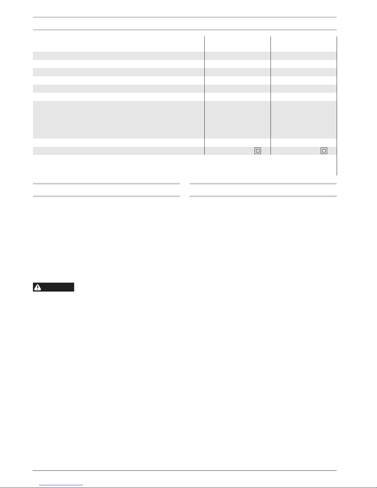
Rotary Hammer GBH 3-28 E
PROFESSIONAL
GBH 3-28 FE
PROFESSIONAL
Article number 0 611 239 7.. 0 611 249 7..
Rated power input W 720 720
Rated speed rpm 0–800 0–800
Impact rate bpm 0–4000 0–4000
Impact energy per stroke J 3.3 3.3
Tool holder SDS-plus SDS-plus
Max. drilling dia.
– Concrete (with twist drill)
– Brickwork (with core bit)
–Steel
– Wood
mm
mm
mm
mm
28
80
13
30
28
80
13
30
Weight according to EPTA-Procedure 01/2003 kg 3.3 3.4
Protection class /II /II
The values given are valid for nominal voltages [U] of 230/240 V. For lower voltage and models for specific countries, these
values can vary.
Please observe the article number on the type plate of your machine. The trade names of the individual machines may vary.
WARNING
English | 171 619 929 719 • 13.9.06
Declaration of Conformity
We declare under our sole responsibility that this
product is in conformity with the following standards
or standardization documents: EN 60745 according
to the provisions of the directives 89/336/EEC,
98/37/EC.
01.09.2006, Robert Bosch GmbH, Power Tools Division
D-70145 Leinfelden-Echterdingen
Assembly
f Before any work on the machine itself, pull
the mains plug.
Auxiliary Handle
f Operate your machine only with the auxiliary
handle 8.
The auxiliary handle 8 can be set to any position for a
secure and low-fatigue working posture.
Turn the bottom part of the auxiliary handle 8 in counterclockwise direction and swivel the auxiliary handle
8 to the desired position. Then retighten the bottom
part of the auxiliary handle 8 by turning in clockwise
direction.
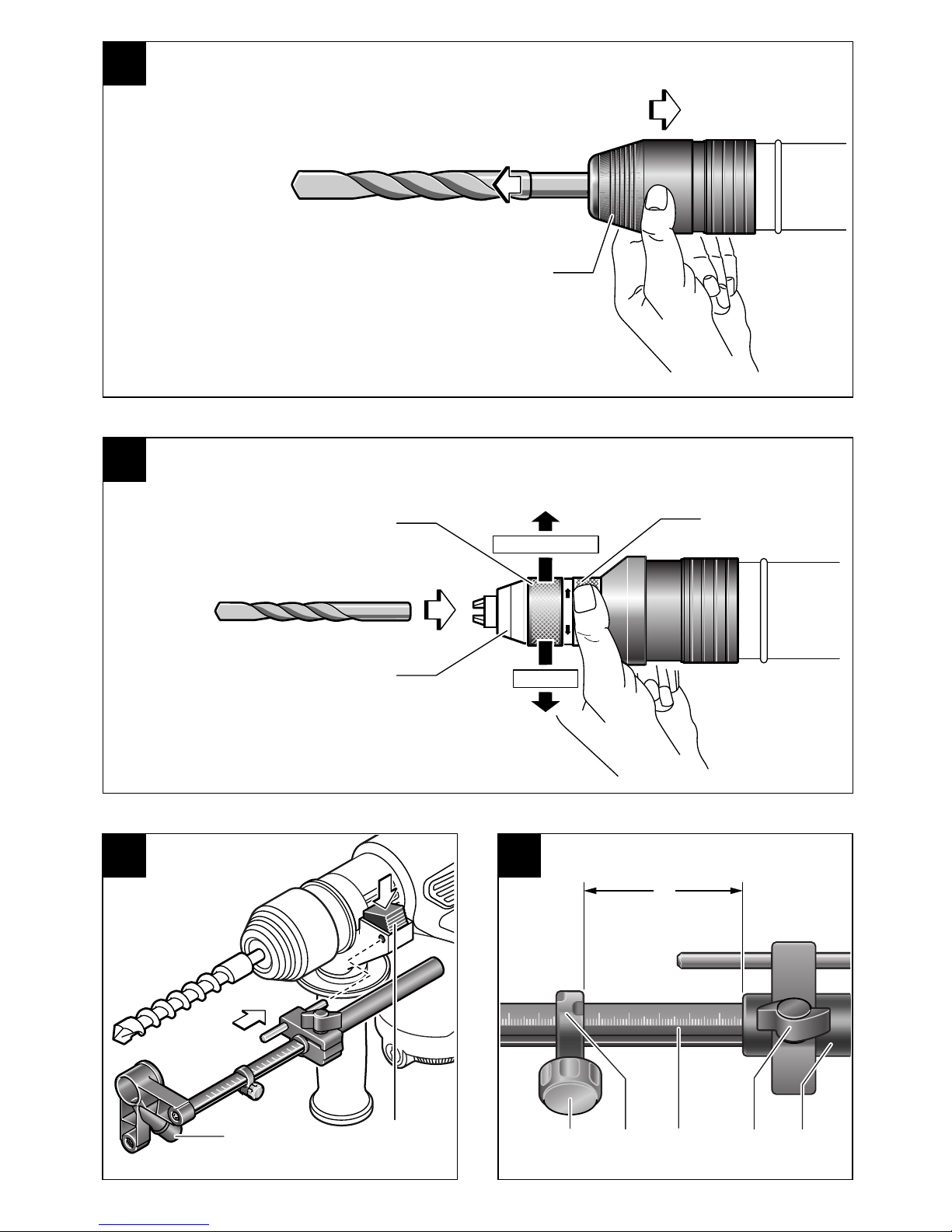
Adjusting the Drilling Depth (see figure A)
The required drilling depth X can be set with the
depth stop 9.
Press the button for the depth stop adjustment 5 and
insert the depth stop into the auxiliary handle 8.
Insert the SDS-plus drilling tool to the stop into the
SDS-plus tool holder. Otherwise, the movability of the
SDS-plus drilling tool can lead to incorrect adjustment
of the drilling depth.
Pull out the depth stop until the distance between the
tip of the drill bit and the tip of the depth stop correspond with the desired drilling depth X.
The knurled surface of the depth stop 9 must face
upward.
Selecting the Tool Holder
For hammer drilling, SDS-plus drilling tools that can
be inserted into the SDS-plus tool holder 1 are
required.
For drilling without impact in wood, metal, ceramic
and plastic, use non-SDS-plus drilling tools (e. g. drill
bits with cylindrical shank). A keyless or a key type drill
chuck is required for such drilling tools.
Note: Do not use drilling tools without SDS-plus for
hammer drilling! Drilling tools without SDS-plus as
well as the tool holder are damaged when used for
hammer drilling.
GBH 3-28 FE: The SDS-plus tool holder 1 can easily
be exchanged against the keyless replacement
chuck 13 provided.
Changing the Tool Holder
Dismounting the SDS-plus Tool Holder or the
Keyless Replacement Chuck (see figure B)
Pull the lock ring of the tool holder 4 firmly in the direction of the arrow, hold it in this position and pull off the
tool holder 1 or the keyless replacement chuck 13
toward the front.
After removing, protect the tool holder 1 or the keyless
replacement chuck 13 against contamination. Lightly
lubricate the engaging grooves, if required.
Mounting the SDS-plus Tool Holder or the Keyless Replacement Chuck
Grasp the tool holder 1 or the keyless replacement
chuck 13 completely with your hand. Slide the tool
holder 1 or the keyless replacement chuck 13 with a
turning motion onto the drill chuck mounting until a
distinct latching noice is heard.
The tool holder 1 or the keyless replacement chuck 13
is automatically locked. Check the locking effect by
pulling the tool holder.
Changing the Key Type Drill Chuck
(GBH 3-28 E) (see figure C)
Mounting the Key Type Drill Chuck
Screw the SDS-plus adapter shank 12 into a key type
drill chuck 11. Secure the key type drill chuck 11 with
the securing screw 10. Please observe that the
securing screw has a left-hand thread.
Clean the shank end of the adapter shank and apply a
light coat of grease.
Insert the key type drill chuck with the adapter shank
into the tool holder with a turning motion until it automatically locks.
Check the locking effect by pulling the key type drill
chuck.
Dismounting the Key Type Drill Chuck
Push the locking sleeve 3 toward the rear and pull out
the key type drill chuck 11.
Dr. Egbert Schneider
Senior Vice President
Engineering
Dr. Eckerhard Strötgen
Head of Product
Certification

18 | English 1 619 929 719 • 13.9.06
Changing the Tool
With the SDS-plus tool holder, simple and convenient
tool changing is possible without additional aids.
As a requirement of the system, the SDS-plus drilling
tool can move freely. This causes a certain radial runout at no-load, which has no effect on the accuracy of
the drill hole, as the drill bit centres itself upon drilling.
The dust protection cap 2 largely prevents the entry of
drilling dust into the tool holder during operation.
When inserting the tool, take care that the dust protection cap 2 is not damaged.
f A damaged dust protection cap should be
changed immediately. We recommend having this carried out by an after-sales service.
Inserting SDS-plus Drilling Tools (see figure D)
Clean and lightly grease the shank end of the tool.
Insert the tool in a twisting manner into the tool holder
until it latches itself.
Check the latching by pulling the tool.
Removing SDS-plus Drilling Tools
(see figure E)
Push back the locking sleeve 3 and remove the tool.
Inserting Drilling Tools without SDS-plus
(GBH 3-28 FE) (see figure F)
Note: Do not use drilling tools without SDS-plus for
hammer drilling! Drilling tools without SDS-plus as
well as the tool holder are damaged when used for
hammer drilling.
Insert the keyless replacement chuck 13.
Firmly hold the retaining ring of the keyless replace-
ment chuck 13. Open the keyless replacement chuck
by turning the front sleeve in the direction of the symbol “ ”.
Insert the drilling tool into the keyless replacement
chuck 13. Firmly hold the retaining ring of the keyless
replacement chuck 13 and turn the front sleeve in the
direction of the symbol “ ”.
Set the selector switch 6 to the “Drilling” symbol.
Removing Drilling Tools without SDS-plus
(GBH 3-28 FE) (see figure F)
Firmly hold the retaining ring of the keyless replacement chuck 13. Open the keyless replacement chuck
by turning the front sleeve in the direction of the symbol “ ”.
Remove the drilling tool.
Inserting Drilling Tools without SDS-plus
(GBH 3-28 E)
Note: Do not use drilling tools without SDS-plus for
hammer drilling! Drilling tools without SDS-plus as
well as the tool holder are damaged when used for
hammer drilling.
Insert the key type drill chuck 11.
Open the key type drill chuck 11 by turning until the
tool can be inserted. Insert the tool.
Insert the chuck key into the corresponding holes of
the key type drill chuck 11 and clamp the tool uniformly.
Set the selector switch 6 to the “Drilling” symbol.
Removing Drilling Tools without SDS-plus
(GBH 3-28 E)
Turn the sleeve of the key type drill chuck 11 with the
drill chuck key in anticlockwise direction until the drilling tool can be removed.
Dust Extraction with the Dust Extraction Attachment (Accessory)
Mounting the Dust Extraction Attachment
(see figure G)
For dust extraction, the dust extraction attachment
(accessory) is required. When drilling, the dust extraction attachment retracts so that the attachment head
is always close to the surface at the drill hole.
Press the button for depth stop adjustment 5 and
remove the depth stop 9. Press button 5 again and
insert the dust extraction attachment into the auxiliary
handle 8 from the front.
Connect an extraction hose (diameter 19 mm, accessory) to the extraction sleeve 16 of the dust extraction
attachment.
The vacuum cleaner must be suitable for the material
being worked.
When vacuuming dry dust that is especially detrimental to health or carcinogenic, use a special vacuum
cleaner.
Adjusting the Drilling Depth on the Dust Extraction Attachment (see figure H)
The required drilling depth X can also be adjusted
when the dust extraction attachment is mounted.
Insert the SDS-plus drilling tool to the stop into the
SDS-plus tool holder. Otherwise, the movability of the
SDS-plus drilling tool can lead to incorrect adjustment
of the drilling depth.
Loosen the wing bolt 20 on the dust extraction attachment.
Without switching the power tool on, apply it firmly to
the drilling location. The SDS-plus drilling tool must
face against the surface.
 Loading...