


 OBJ_BUCH-316-001.book Page 1 Tuesday, February 20, 2007 9:52 AM
GBH 2-26 E
GBH 2-26 RE
GBH 2-26 DE
GBH 2-26 DRE
GBH 2-26 DFR
Professional
Operating Instructions
Petunjuk-Petunjuk untuk Penggunaan
Hõëng dÿn s¥ dông
Instructions d’emploi
ÁU~²Ýœ ÈULM¼«—
OBJ_BUCH-316-001.book Page 2 Tuesday, February 20, 2007 9:52 AM
English . . . . . . . . . . . . . . . . . . . . . . . . . . |
. . . Page |
6 |
. . . . . . . . . . . . . . . . . . . . . . . . . . . . . |
. . . . . 14 |
|
. . . . . . . . . . . . . . . . . . . . . . . . . . . . . |
. . . . . 21 |
|
. . . . . . . . . . . . . . . . . . . . . . . . . . . . |
. . . . . |
27 |
. . . . . . . . . . . . . . . . . . . . . . . . . . |
. . . . |
34 |
Bahasa Indonesia . . . . . . . . . . . . . . . . . |
Halaman |
41 |
Tiøng Vi·t . . . . . . . . . . . . . . . . . . . . . . . . |
. .Trang |
50 |
Français . . . . . . . . . . . . . . . . . . . . . . . . . . |
. . Page |
57 |
. . . . . . . . . . . . . . . . . . . . . . . . . . . . . |
. . ΔΤϔλ |
65 |
vÝ—U . . . . . . . . . . . . . . . . . . . . . . . . . . . |
. . ϪΤϔλ |
72 |
2 |
|
|
|
1 619 929 728 • 20.2.07 |
|||
|
|
|
|
|
|
|
|
|
|
|
|
|
|
|
|
|
|
|
|
|
|
|
|

OBJ_BUCH-316-001.book Page 3 Tuesday, February 20, 2007 9:52 AM
A
|
14 |
C |
17 |
|
16 |
15 |
|
E |
|
18
3
B
13
3
X |
12 |
|
|
D |
|
6 |
|
F |
1 619 929 728 • 20.2.07 |
OBJ_BUCH-316-001.book Page 4 Tuesday, February 20, 2007 9:52 AM |
||||
G |
|
5 |
|
H |
|
|
|
|
|
|
|
|
|
20 |
|
|
|
|
19 |
I |
|
|
|
J |
|
19 |
20 |
|
|
|
|
|
|
|
|
|
|
|
12 |
|
|
|
|
14 |
|
|
|
|
21 |
K |
|
X |
|
L |
22 |
23 |
24 |
25 |
27 |
26 |
||||
4 |
|
|
|
1 619 929 728 • 20.2.07 |
OBJ_BUCH-316-001.book Page 5 Tuesday, February 20, 2007 9:52 AM |
|
||
1 |
|
GBH 2-26 DFR |
|
|
Professional |
|
|
|
|
|
|
|
|
|
7 |
2 |
6 |
|
|
|
|
|
|
5 |
|
|
8 |
4 |
|
|
|
3 |
|
|
9 |
|
|
|
|
|
|
10 |
|
|
|
11 |
|
|
|
12 |
|
|
|
13 |
|
|
|
14 |
|
|
|
GBH 2-26 E |
|
|
|
GBH 2-26 RE |
|
GBH 2-26 E |
|
Professional |
|
|
|
|
|
GBH 2-26 RE |
|
|
|
GBH 2-26 DE |
|
|
|
GBH 2-26 DRE |
|
|
|
Professional |
|
|
|
5 |
|
|
1 619 929 728 • 20.2.07 |
OBJ_BUCH-316-001.book Page 6 Tuesday, February 20, 2007 9:52 AM
General Power Tool
Safety Warnings
WARNING |
Read all safety warnings and all |
|
instructions. Failure to follow the |
||
|
warnings and instructions may result in electric shock, fire and/or serious injury.
Save all warnings and instructions for future reference.
The term “power tool” in the warnings refers to your mains-operated (corded) power tool or battery-oper- ated (cordless) power tool.
1)Work area safety
a)Keep work area clean and well lit. Cluttered or dark areas invite accidents.
b)Do not operate power tools in explosive atmospheres, such as in the presence of flammable liquids, gases, or dust. Power tools create sparks which may ignite the dust or fumes.
c)Keep children and bystanders away while operating a power tool. Distractions can cause you to lose control.
2)Electrical safety
a)Power tool plugs must match the outlet. Never modify the plug in any way. Do not use any adapter plugs with earthed (grounded) power tools. Unmodified plugs and matching outlets will reduce the risk of electric shock.
b)Avoid body contact with earthed or grounded surfaces, such as pipes, radiators, ranges and refrigerators. There is an increased risk of electric shock if your body is earthed or grounded.
c)Do not expose power tools to rain or wet conditions. Water entering a power tool will increase the risk of electric shock.
d)Do not abuse the cord. Never use the cord for carrying, pulling or unplugging the power tool. Keep cord away from heat, oil, sharp edges or moving parts. Damaged or entangled cords increase the risk of electric shock.
e)When operating a power tool outdoors, use an extension cord suitable for outdoor use.
Use of a cord suitable for outdoor use reduces the risk of electric shock.
f)If operating a power tool in a damp location is unavoidable, use a ground fault circuit interrupter (GFCI) or an earth leakage circuit breaker (ELCB). Use of a GFCI or an ELCB reduces the risk of electric shock.
3)Personal safety
a)Stay alert, watch what you are doing and use common sense when operating a power tool. Do not use a power tool while you are tired or under the influence of drugs, alcohol, or medication. A moment of inattention while operating power tools may result in serious personal injury.
b)Use personal protective equipment. Always wear eye protection. Protective equipment such as dusk mask, non-skid safety shoes, hard hat or hearing protection used for appropriate conditions will reduce personal injuries.
c)Prevent unintentional starting. Ensure the switch is in the off position before connecting to power source and/or battery pack, picking up or carrying the tool. Carrying power tools with your finger on the switch or energizing power tools that have the switch on invites accidents.
d)Remove any adjusting key or wrench before turning the power tool on. A wrench or a key that is left attached to a rotating part of the power tool may result in personal injury.
e)Do not overreach. Keep proper footing and balance at all times. This enables better control of the power tool in unexpected situations.
f)Dress properly. Do not wear loose clothing or jewelry. Keep your hair, clothing, and gloves away from moving parts. Loose clothes, jewelry, or long hair can be caught in moving parts.
g)If devices are provided for the connection of dust extraction and collection facilities, ensure these are connected and properly used. Use of dust collection can reduce dustrelated hazards.
4)Power tool use and care
a)Do not force the power tool. Use the correct power tool for your application. The correct power tool will do the job better and safer at the rate for which it is designed.
b)Do not use the power tool if the switch does not turn it on or off. Any power tool that cannot be controlled with the switch is dangerous and must be repaired.
c)Disconnect the plug from the power source and/or the battery pack from the power tool before making any adjustments, changing accessories, or storing power tools. Such preventive safety measures reduce the risk of starting the power tool accidentally.
|
6 | English |
|
|
1 619 929 728 • 20.2.07 |
|||
|
|
|
|
|
|
|
|
|
|
|
|
|
|
|
|
|
|
|
|
|
|
|
|
 OBJ_BUCH-316-001.book Page 7 Tuesday, February 20, 2007 9:52 AM
d)Store idle power tools out of the reach of children and do not allow persons unfamiliar with the power tool or these instructions to operate the power tool. Power tools are dangerous in the hands of untrained users.
e)Maintain power tools. Check for misalignment or binding of moving parts, breakage of parts and any other condition that may affect the power tool’s operation. If damaged, have the power tool repaired before use. Many accidents are caused by poorly maintained power tools.
f)Keep cutting tools sharp and clean. Properly maintained cutting tools with sharp cutting edges are less likely to bind and are easier to control.
g)Use the power tool, accessories, tool bits etc. in accordance with these instructions, taking into account the working conditions and the work to be performed. Use of the power tool for operations different from those intended could result in a hazardous situation.
5)Service
a)Have your power tool serviced by a qualified repair person using only identical replacement parts. This will ensure that the safety of the power tool is maintained.
Power Tool-specific
Safety Warnings
fWear hearing protection. Exposure to noise can cause hearing loss.
fUse the auxiliary handle supplied with the power tool. Loss of control over the power tool can cause personal injury.
fUse suitable detectors to determine if utility lines are hidden in the work area or call the local utility company for assistance. Contact with electric lines can lead to fire and electric shock. Damaging a gas line can lead to explosion. Penetrating a water line causes property damage or may cause an electric shock.
fWhen working with the power tool, always hold it firmly with both hands and provide for a secure stance. The power tool is guided more secure with both hands.
fSecure the workpiece. A workpiece clamped with clamping devices or in a vice is held more secure than by hand.
f Do not work materials containing asbestos.
Asbestos is considered carcinogenic.
f Take protective measures when dust can develop during working that is harmful to one’s health, combustible or explosive. Example: Some dusts are regarded as carcinogenic. Wear a dust mask and work with dust/chip extraction when connectable.
fKeep your workplace clean. Blends of materials are particularly dangerous. Dust from light alloys can burn or explode.
fAlways wait until the power tool has come to a complete stop before placing it down. The tool insert can jam and lead to loss of control over the power tool.
fDo not use the power tool with a damaged cord. Do not touch the damaged cord and pull the plug from the outlet when the cord is damaged while working. Damaged cords increase the risk of an electric shock.
Functional Description
Read all safety warnings and all instructions. Failure to follow the warnings and instructions may result in electric shock, fire and/or serious injury.
While reading the operating instructions, unfold the graphics page for the tool and leave it open.
Intended Use
GBH 2-26 E/RE
The machine is intended for hammer drilling in concrete, brick and stone. It is also suitable for drilling without impact in wood, metal, ceramic and plastic. Machines with electronic control and right/left rotation are also suitable for screwdriving and thread cutting.
GBH 2-26 DE/DRE/DFR
The machine is intended for hammer drilling in concrete, brick and stone, as well as for light chiseling work. It is also suitable for drilling without impact in wood, metal, ceramic and plastic. Machines with electronic control and right/left rotation are also suitable for screwdriving and thread cutting.
|
1 619 929 728 • 20.2.07 |
|
|
English | 7 |
|||
|
|
|
|
|
|
|
|
|
|
|
|
|
|
|
|
|
|
|
|
|
|
|
|
OBJ_BUCH-316-001.book Page 8 Tuesday, February 20, 2007 9:52 AM
Technical Data
Rotary Hammer GBH ... |
|
2-26 E |
2-26 RE |
2-26 DE |
2-26 DRE |
2-26 DFR |
Professional |
|
|
|
|
|
|
Article number |
|
0 611 251 6.. |
0 611 251 7.. |
0 611 253 6.. |
0 611 253 7.. |
0 611 254 7.. |
Speed control |
|
z |
z |
z |
z |
z |
Stop rotation |
|
– |
– |
z |
z |
z |
Right/left rotation |
|
– |
z |
– |
z |
z |
Quick change chuck |
|
– |
– |
– |
– |
z |
Rated power input |
W |
800 |
800 |
800 |
800 |
800 |
Impact frequency at rated |
|
|
|
|
|
|
speed |
bpm |
0 – 4000 |
0 – 4000 |
0 – 4000 |
0 – 4000 |
0 – 4000 |
Impact energy per stroke |
J |
0 –3.0 |
0 –3.0 |
0– 3.0 |
0– 3.0 |
0– 3.0 |
Rated speed |
rpm |
0 – 900 |
0– 900 |
0– 900 |
0 – 900 |
0 – 900 |
Tool holder |
|
SDS-plus |
SDS-plus |
SDS-plus |
SDS-plus |
SDS-plus |
Spindle collar diameter |
mm |
50 |
50 |
50 |
50 |
50 |
Drilling diameter, max.: |
mm |
26 |
26 |
26 |
26 |
26 |
– Concrete |
||||||
– Brickwork (with core bit) |
mm |
68 |
68 |
68 |
68 |
68 |
– Steel |
mm |
13 |
13 |
13 |
13 |
13 |
– Wood |
mm |
30 |
30 |
30 |
30 |
30 |
Weight according to |
|
|
|
|
|
|
EPTA-Procedure 01/2003 |
kg |
2.7 |
2.7 |
2.7 |
2.7 |
2.9 |
Protection class |
|
/ II |
/ II |
/ II |
/ II |
/ II |
The values given are valid for nominal voltages [U] of 230/240 V. For lower voltages and models for specific countries, these values can vary.
Please observe the article number on the type plate of your power tool. The trade names of individual tools may vary.
Product Features
The numbering of the product features refers to the illustration of the power tool on the graphics page.
1 Quick change keyless chuck (GBH 2-26 DFR)
2 SDS-plus quick change chuck (GBH 2-26 DFR)
3 SDS-plus tool holder
4 Dust protection cap
5 Locking sleeve
6Lock ring for rapid-change chuck (GBH 2-26 DFR)
7Rotational direction switch (GBH 2-26 RE/DRE/DFR)
8 Lock-on button for On/Off switch
9 On/Off switch
10Release button for mode selector switch
11Mode selector switch
12Button for depth stop adjustment
13Depth stop
14Auxiliary handle
15Securing screw for key type drill chuck*
16Key-type drill chuck*
17SDS-plus adapter shank for drill chuck*
18Drill chuck mounting (GBH 2-26 DFR)
19Front sleeve of the quick change keyless chuck (GBH 2-26 DFR)
20Retaining ring of the quick change keyless chuck (GBH 2-26 DFR)
21Extraction sleeve of the dust extraction attachment*
22Clamping screw for the dust extraction attachment*
23Depth stop of the dust extraction attachment*
24Telescopic pipe of the dust extraction attachment*
25Wing bolt of the dust extraction attachment*
26Guide pipe of the dust extraction attachment*
27Universal bit holder with SDS-plus shank*
*The accessories illustrated or described are not included as standard delivery.
|
8 | English |
|
|
1 619 929 728 • 20.2.07 |
|||
|
|
|
|
|
|
|
|
|
|
|
|
|
|
|
|
|
|
|
|
|
|
|
|

OBJ_BUCH-316-001.book Page 9 Tuesday, February 20, 2007 9:52 AM
Assembly
fBefore any work on the power tool itself, pull the mains plug.
Auxiliary Handle
fOperate your power tool only with the auxiliary handle 14.
Rotating the Auxiliary Handle (see figure A)
The auxiliary handle 14 can be set to any position for a secure and low-fatigue working posture.
Turn the bottom part of the auxiliary handle 14 in counterclockwise direction and swivel the auxiliary handle 14 to the desired position. Then retighten the bottom part of the auxiliary handle 14 by turning in clockwise direction.
Pay attention that the clamping band of the auxiliary handle is positioned in the groove on the housing as intended for.
Adjusting the Drilling Depth (see figure B)
The required drilling depth X can be set with the depth stop 13.
Press the button for the depth stop adjustment 12 and insert the depth stop into the auxiliary handle 14.
The knurled surface of the depth stop 13 must face downward.
Insert the SDS-plus drilling tool to the stop into the SDS-plus tool holder 3. Otherwise, the movability of the SDS-plus drilling tool can lead to incorrect adjustment of the drilling depth.
Pull out the depth stop until the distance between the tip of the drill bit and the tip of the depth stop correspond with the desired drilling depth X.
Selecting Drill Chucks and Tools
For hammer drilling and chiseling, SDS-plus tools are required that are inserted in the SDS-plus drill chuck.
For drilling without impact in wood, metal, ceramic and plastic as well as for screwdriving and thread cutting, tools without SDS-plus are used (e.g., drills with cylindrical shank). For these tools, a keyless chuck or a key type drill chuck are required.
Note: Do not use tools without SDS-plus for hammer drilling or chiseling! Tools without SDS-plus and their drill chucks are damaged by hammer drilling or chiseling.
GBH 2-26 DFR: The SDS-plus quick change chuck 2 can easily be replaced against the quick change keyless chuck 1 provided.
Changing the Key Type Drill Chuck
(GBH 2-26 E/RE/DE/DRE)
To work with tools without SDS-plus (e. g., drills with cylindrical shank), a suitable drill chuck must be mounted (key type drill chuck or keyless chuck, accessories).
Mounting the Key Type Drill Chuck (see figure C)
Screw the SDS-plus adapter shank 17 into a key type drill chuck 16. Secure the key type drill chuck 16 with the securing screw 15. Please observe that the securing screw has a left-hand thread.
Inserting the Key Type Drill Chuck (see figure C)
Clean the shank end of the adapter shank and apply a light coat of grease.
Insert the key type drill chuck with the adapter shank into the tool holder with a turning motion until it automatically locks.
Check the locking effect by pulling the key type drill chuck.
Removing the Key Type Drill Chuck
Push the locking sleeve 5 toward the rear and pull out the key type drill chuck 16.
Removing/Inserting the Quick Change
Chuck (GBH 2-26 DFR)
Removing the Quick Change Chuck (see figure D)
Pull the lock ring for the quick change chuck 6 toward the rear, hold it in this position and pull off the SDS-plus quick change chuck 2 or the quick change keyless chuck 1 toward the front.
After removing, protect the replacement chuck against contamination.
Inserting the Quick Change Chuck (see figure E)
Before inserting, clean the quick change chuck and apply a light coat of grease to the shank end.
Grasp the SDS-plus quick change chuck 2 or the quick change keyless chuck 1 completely with your hand. Slide the quick change chuck with a turning motion onto the drill chuck mounting 18 until a distinct latching noise is heard.
The quick change chuck is automatically locked. Check the locking effect by pulling the quick change chuck.
|
1 619 929 728 • 20.2.07 |
|
|
English | 9 |
|||
|
|
|
|
|
|
|
|
|
|
|
|
|
|
|
|
|
|
|
|
|
|
|
|
OBJ_BUCH-316-001.book Page 10 Tuesday, February 20, 2007 9:52 AM
Changing the Tool
The dust protection cap 4 largely prevents the entry of drilling dust into the tool holder during operation. When inserting the tool, take care that the dust protection cap 4 is not damaged.
f A damaged dust protection cap should be changed immediately. We recommend having this carried out by an after-sales service.
Inserting SDS-plus Drilling Tools (see figure F)
The SDS-plus drill chuck allows for simple and convenient changing of drilling tools without the use of additional tools.
GBH 2-26 DFR: Insert the SDS-plus quick change chuck 2.
Clean and lightly grease the shank end of the tool.
Insert the tool in a twisting manner into the tool holder until it latches itself.
Check the latching by pulling the tool.
As a requirement of the system, the SDS-plus drilling tool can move freely. This causes a certain radial runout at no-load, which has no effect on the accuracy of the drill hole, as the drill bit centers itself upon drilling.
Removing SDS-plus Drilling Tools (see figure G)
Push back the locking sleeve 5 and remove the tool.
Inserting Drilling Tools without SDS-plus (GBH 2-26 E/RE/DE/DRE)
Note: Do not use tools without SDS-plus for hammer drilling or chiseling! Tools without SDS-plus and their drill chucks are damaged by hammer drilling or chiseling.
Insert a key type drill chuck 16 (see “Changing the Key Type Drill Chuck”, page 9).
Open the key-type drill chuck 16 by turning until the tool can be inserted. Insert the tool.
Insert the chuck key into the corresponding holes of the key type drill chuck 16 and clamp the tool uniformly.
Turn the mode selector switch 11 to the “Drilling” position.
Removing Drilling Tools without SDS-plus (GBH 2-26 E/RE/DE/DRE)
Turn the sleeve of the key type drill chuck 16 with the drill chuck key in anticlockwise direction until the drilling tool can be removed.
Inserting Drilling Tools without SDS-plus (GBH 2-26 DFR) (see figure H)
Note: Do not use tools without SDS-plus for hammer drilling or chiseling! Tools without SDS-plus and their drill chucks are damaged by hammer drilling or chiseling.
Insert the quick change keyless chuck 1.
Firmly hold the retaining ring 20 of the quick change chuck. Open the tool holder by turning the front sleeve 19 until the tool can be inserted. Tightly hold the retaining ring 20 and firmly turn the front sleeve 19 in the direction of the arrow until a distinct latching noise can be heard.
Check the tight seating by pulling the tool.
Note: If the tool holder was opened to the stop, then the latching noise possibly may be heard while closing the tool holder and the tool holder will not close.
In this case, turn the front sleeve 19 once in the opposite direction of the arrow. Afterwards, the tool holder can be closed (tightened) again.
Turn the mode selector switch 11 to the “Drilling” position.
Removing Drilling Tools without SDS-plus (GBH 2-26 DFR) (see figure I)
Firmly hold the retaining ring 20 of the quick change chuck. Open the tool holder by turning the front sleeve 19 in the direction of the arrow until the tool can be removed.
Dust Extraction with the Dust Extraction Attachment (Accessory)
Mounting the Dust Extraction Attachment (see figure J)
For dust extraction, the dust extraction attachment (accessory) is required. When drilling, the dust extraction attachment retracts so that the attachment head is always close to the surface at the drill hole.
Press the button for depth stop adjustment 12 and remove the depth stop 13. Press button 12 again and insert the dust extraction attachment into the auxiliary handle 14 from the front.
Connect an extraction hose (diameter 19 mm, accessory) to the extraction sleeve 21 of the dust extraction attachment.
The vacuum cleaner must be suitable for the material being worked.
When vacuuming dry dust that is especially detrimental to health or carcinogenic, use a special vacuum cleaner.
|
10 | English |
|
|
1 619 929 728 • 20.2.07 |
|||
|
|
|
|
|
|
|
|
|
|
|
|
|
|
|
|
|
|
|
|
|
|
|
|
OBJ_BUCH-316-001.book Page 11 Tuesday, February 20, 2007 9:52 AM
Adjusting the Drilling Depth on the Dust Extraction Attachment (see figure K)
The required drilling depth X can also be adjusted when the dust extraction attachment is mounted.
Insert the SDS-plus drilling tool to the stop into the SDS-plus tool holder 3. Otherwise, the movability of the SDS-plus drilling tool can lead to incorrect adjustment of the drilling depth.
Loosen the wing bolt 25 on the dust extraction attachment.
Without switching the power tool on, apply it firmly to the drilling location. The SDS-plus drilling tool must face against the surface.
Position the the guide pipe 26 of the dust extraction attachment in its holding fixture in such a manner that the head of the dust extraction attachment faces against the surface to be drilled. Do not slide the guide pipe 26 further over the telescopic pipe 24 of the dust extraction attachment than required, so that as much as possible of the scale 24 on the telescopic pipe remains visible.
Retighten the wing bolt 25 again. Loosen the clamping screw 22 on the depth stop of the dust extraction attachment.
Move the depth stop 23 on the telescopic pipe 24 in such a manner that the clearance X shown in the figure corresponds with the required drilling depth.
Tighten the clamping screw 22 in this position.
Operation
Starting Operation
fObserve correct mains voltage! The voltage of the power source must agree with the voltage specified on the type plate of the power tool.
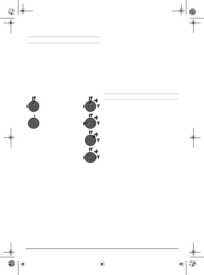
Setting the Operating Mode
The operating mode of the power tool is selected with the mode selector switch 11.
Note: Change the operating mode only when the machine is switched off! Otherwise, the machine can be damaged.
To change the operating mode, push the release button 10 and turn the mode selector switch 11 to the requested position until it can be heard to latch.
GBH 2-26 E/RE |
GBH 2-26 DE/ |
|
DRE/DFR |
Position for hammer drilling in concrete or stone
Position for drilling without impact in wood, metal, ceramic and plastic as well as for screwdriving and thread cutting
Vario-Lock position for adjustment of the chiseling position
The mode selector switch 11 does not latch in this position.
Position for chiseling
Reversing the Rotational Direction (GBH 2-26 RE/DRE/DFR)
The rotational direction switch 7 is used to reverse the rotational direction of the machine. However, this is not possible with the On/Off switch 9 actuated.

 Right rotation: Turn the selector switch for drilling/hammer drilling 7 on both sides to the stop in the position
  .
.

 Left rotation: Turn the selector switch for drilling/hammer drilling 7 on both sides to the stop in the position
  .
.
Set the direction of rotation for hammer drilling, drilling and chiseling always to right rotation.
Switching On and Off
To start the machine, press the On/Off switch 9.
To lock the On/Off switch, keep it pressed and additionally push the lock-on button 8.
To switch off the machine, release the On/Off switch 9. When the On/Off switch 9 is locked, press it first and then release it.
Setting the Speed/Impact Rate
The speed/impact rate of the switched on power tool can be variably adjusted, depending on how far the On/Off switch 9 is pressed.
Light pressure on the On/Off switch 9 results in low speed/impact rate. Further pressure on the switch increases the speed/impact rate.
|
1 619 929 728 • 20.2.07 |
|
|
English | 11 |
|||
|
|
|
|
|
|
|
|
|
|
|
|
|
|
|
|
|
|
|
|
|
|
|
|
OBJ_BUCH-316-001.book Page 12 Tuesday, February 20, 2007 9:52 AM
Overload Clutch
fIf the tool insert becomes caught or jammed, the drive to the drill spindle is interrupted. Because of the forces that occur, always hold the power tool firmly with both hands and provide for a secure stance.
fIf the power tool jams, switch the machine off and loosen the tool insert. When switching the power tool on with the drilling tool jammed, high reaction torques can occur.
Working Instructions
Changing the Chiselling Position (Vario-Lock) (GBH 2-26 DE/DRE/DFR)
The chisel can be locked in 36 positions. In this manner, the optimum working position can be set for each application.
Insert the chisel into the tool holder.
Turn the mode selector switch 11 to the “Vario-Lock” position (see “Setting the Operating Mode”, page 11).
Turn the tool holder to the desired chiselling position.
Turn the mode selector switch 11 to the chiseling position. The tool holder is now locked.
For chiseling, set the rotation direction to right rotation.
Inserting Screwdriver Bits (see figure L)
f Apply the power tool to the screw/nut only when it is switched off. Rotating tool inserts can slip off.
To work with screwdriver bits, a universal bit holder 27 with SDS-plus shank (accessory) is required.
Clean the shank end of the adapter shank and apply a light coat of grease.
Insert the universal bit holder with a turning motion into the tool holder until it automatically locks.
Check the locking effect by pulling the universal bit holder.
Insert a screwdriver bit into the universal bit holder. Use only screwdriver bits that match the screw head.
To remove the universal bit holder, pull the locking sleeve 5 toward the rear and remove the universal bit holder 27 out of the tool holder.
Maintenance and Service
Maintenance and Cleaning
fBefore any work on the power tool itself, pull the mains plug.
fFor safe and proper working, always keep the power tool and the ventilation slots clean.
fA damaged dust protection cap should be changed immediately. We recommend having this carried out by an after-sales service.
Clean the tool holder 3 each time after using.
If the power tool should fail despite the care taken in manufacturing and testing procedures, repair should be carried out by an after-sales service center for Bosch power tools.
In all correspondence and spare parts orders, please always include the 10-digit article number given on the type plate of the power tool.
Service and Customer Assistance
Exploded views and information on spare parts can be found under:
www.bosch-pt.com
In case of a claim, repair or purchase of replacement parts or in case of queries or other problems, please contact your local dealer or Bosch representative.
People’s Republic of China
Website: www.bosch-pt.com.cn
China Mainland
Bosch Power Tools (China) Co., Ltd. 567, Bin Kang Road
Bin Jiang District 310052 Hangzhou, P.R.China
Service Hotline: . . . . . . . . . . . . . . . . . . 800 8 20 84 84. . . . . . . . . . . . . . . . . . . . . . . . +86 571 87 77 43 38 Fax . . . . . . . . . . . . . . . . . . . . . . . . +86 571 87 77 45 02
HK and Macau Special Administrative Regions
Melchers (H.K.) Ltd, Room 1210 Shun Tak Centre, West-Tower
168 – 200 Connaught Road, Central Hong Kong Customer Service Hotline: . . . . . . . +852 25 89 15 61 Fax . . . . . . . . . . . . . . . . . . . . . . . . . . . +852 25 48 79 14 E-Mail: bosch@melchers.com.hk
|
12 | English |
|
|
1 619 929 728 • 20.2.07 |
|||
|
|
|
|
|
|
|
|
|
|
|
|
|
|
|
|
|
|
|
|
|
|
|
|
OBJ_BUCH-316-001.book Page 13 Tuesday, February 20, 2007 9:52 AM
Indonesia
P. T. Multi Tehaka
Karang Anyar Permai Block B-24 Jl. Karang Anyar No. 55
Jakarta Pusat 10740 Indonesia
. . . . . . . . . . . . . . . . . . . +62 21 6 59 52 22 (5 lines) Fax. . . . . . . . . . . . . . . . . . . . . . . +62 21 6 59 52 52 – 3 sales@bosch.co.id
www.bosch.co.id
Phillippines
Robert Bosch, Inc. Zuellig Building
Sen. Gil Puyat Avenue
Makati City 1200, Metro Manila Philippines
. . . . . . . . . . . . . . . . . . . . . . . . . . . +63 2 8 17 32 31 www.bosch.com.ph
Malaysia
Robert Bosch (SEA.) Pte. Ltd. No. 8a, Jalan 13/6
Selangor Darul Ehsan
Petaling Jaya 46200 Malaysia
. . . . . . . . . . . . . . . . . . . . . . . . . . +60 3 79 58 30 00 Fax (EW Dept.) . . . . . . . . . . . . . . . +60 3 79 58 38 38 www.bosch.com.sg
Thailand
Robert Bosch Ltd. Liberty Square Building No. 287, 11 Floor Silom Road, Bangrak Bangkok 10500
. . . . . . . . . . . . +66 2 6 31 18 79 – 18 88 (10 lines) Fax. . . . . . . . . . . . . . . . . . . . . . . . . . . +66 2 2 38 47 83 Robert Bosch Ltd., P. O. Box 2054
Bangkok 10501, Thailand
Bosch Service – Training Centre 2869-2869/1 Soi Ban Kluay
Rama IV Road (near old Paknam Railway) Prakanong District
10110 Bangkok Thailand
. . . . . . . . . . . . . . . . . . . . . . . . +66 26 71 78 00 – 4 Fax . . . . . . . . . . . . . . . . . . . . . . . . . . +66 2 2 49 42 96 Fax . . . . . . . . . . . . . . . . . . . . . . . . . . +66 2 2 49 52 99
Singapore
Robert Bosch (SEA.) Pte. Ltd. 38 C Jalan Pemimpin Singapore 915701
Republic of Singapore
. . . . . . . . . . . . . . . . . . . . . . . . . . . . . +65 3 50 54 94 Fax . . . . . . . . . . . . . . . . . . . . . . . . . . . . . +65 3 50 53 27 www.bosch.com.sg
Vietnam
Saigon Trade Center
37 Ton Duc Thang St Ben Nghe Ward
Dist 1
HCMC
Vietnam
. . . . . . . . . . . . . . . . +84 8 9 11 13 74 – 9 11 13 75 Fax . . . . . . . . . . . . . . . . . . . . . . . . . . . +84 8 9 11 13 76
Australia and New Zealand
Robert Bosch Australia Pty. Ltd. RBAU/SPT
1555 Centre Road P.O. Box 66
3168 Clayton/Victoria
. . . . . . . . . . . . . . . . . . . . . +61 (0)1 / 3 00 30 70 44 Fax . . . . . . . . . . . . . . . . . . . . . +61 (0)1 / 3 00 30 70 45 www.bosch.com.au
Disposal
Power tools, accessories and packaging should be sorted for environmental-friendly recycling.
Subject to change without notice.
|
1 619 929 728 • 20.2.07 |
|
|
English | 13 |
|||
|
|
|
|
|
|
|
|
|
|
|
|
|
|
|
|
|
|
|
|
|
|
|
|
OBJ_BUCH-316-001.book Page 14 Tuesday, February 20, 2007 9:52 AM
/
" "
a) 昏暗的工作场所容易导致意外。
易引燃尘埃或易燃蒸汽。
b) 害的发生机率。
c)/
d) 整工具/ ,
e) 助您在突发状况下及时控制住电动工具。
f) 首饰容易被捲入转动的机件中。
b) 容易遭受电击。
高操作者遭受电击的危险。
e) 低操作者遭受电击的危险。
f) 流保护开关可以预防遭受电击。
a) 用电动工具时只要稍微分心便可能发生后果严重 的意外。
b) 将故障的机器送修。
c) 必须先从插座上拔出插头并且/
d) 动工具容易发生意外。
e) 彻底执行机器的维护工作容易导致工作意外。
f) 操作。
|
14 | |
|
|
1 619 929 728 • 20.2.07 |
|||
|
|
|
|
|
|
|
|
|
|
|
|
|
|
|
|
|
|
|
|
|
|
|
|

 OBJ_BUCH-316-001.book Page 15 Tuesday, February 20, 2007 9:52 AM
a) 器的安全性能。
並且/
f 动工具容易造成伤害。
f 固。
f 用手持握工件更牢固。
f 起爆炸。
f 具。
f 头。
GBH 2-26 E/RE
正/ /
GBH 2-26 DE/DRE/DFR
的正常钻。配备电子调节装置和正//
|
1 619 929 728 • 20.2.07 |
|
|
| 15 |
|||
|
|
|
|
|
|
|
|
|
|
|
|
|
|
|
|
|
|
|
|
|
|
|
|
OBJ_BUCH-316-001.book Page 16 Tuesday, February 20, 2007 9:52 AM
GBH ... |
|
2-26 E |
|
2-26 RE |
2-26 DE |
2-26 DRE |
2-26 DFR |
||
Professional |
|
|
|
|
|
|
|
|
|
|
|
0 611 251 6.. |
0 611 251 7.. |
0 611 253 6.. |
0 611 253 7.. |
0 611 254 7.. |
|||
|
|
z |
|
|
z |
z |
z |
z |
|
|
|
– |
|
|
– |
z |
z |
z |
|
/ |
|
– |
|
|
z |
– |
z |
z |
|
|
|
– |
|
|
– |
– |
– |
z |
|
|
|
800 |
|
|
800 |
800 |
800 |
800 |
|
|
/ |
0–4000 |
|
0–4000 |
0–4000 |
0–4000 |
0–4000 |
||
|
|
0–3,0 |
|
0–3,0 |
0–3,0 |
0–3,0 |
0–3,0 |
||
|
/ |
0–900 |
|
0 –900 |
0 –900 |
0 –900 |
0 –900 |
||
|
|
SDS-plus |
|
SDS-plus |
SDS-plus |
SDS-plus |
SDS-plus |
||
|
|
50 |
|
|
50 |
50 |
50 |
50 |
|
|
|
|
|
|
|
|
|
|
|
– |
|
26 |
|
|
26 |
26 |
26 |
26 |
|
– |
|
68 |
|
|
68 |
68 |
68 |
68 |
|
– |
|
13 |
|
|
13 |
13 |
13 |
13 |
|
– |
|
30 |
|
|
30 |
30 |
30 |
30 |
|
|
|
|
|
|
|
|
|
|
|
EPTA-Procedure 01/2003 |
|
2,7 |
|
|
2,7 |
2,7 |
2,7 |
2,9 |
|
|
|
/ II |
|
|
/ II |
/ II |
/ II |
/ II |
|
230/240 V |
|
|
|||||||
|
|
|
|||||||
|
|
|
|
|
14 |
|
|
||
|
|
|
|
|
|
||||
|
|
|
15 |
* |
|
||||
|
|
|
|||||||
16 |
* |
|
|
||||||
1 |
(GBH 2-26 DFR) |
|
17 |
SDS-plus * |
|
||||
|
|
|
|
|
|||||
2 |
SDS-plus- (GBH 2-26 DFR) |
|
18 |
(GBH 2-26 DFR) |
|
||||
|
|
|
|
|
|||||
3 |
SDS-plus |
|
|
19 |
(GBH 2-26 DFR) |
|
|||
|
|
|
|
|
|||||
4 |
|
|
|
20 |
(GBH 2-26 DFR) |
|
|||
|
|
|
|
|
|||||
5 |
|
|
|
21 |
Saugfix * |
|
|||
6 |
(GBH 2-26 DFR) |
|
|
||||||
|
22 |
Saugfix * |
|
||||||
7 |
(GBH 2-26 RE/DRE/DFR) |
|
|||||||
23 |
Saugfix * |
|
|||||||
8 |
|
|
|
|
|||||
|
|
24 |
Saugfix * |
|
|||||
9 |
|
|
|
|
|||||
|
|
|
25 Saugfix * |
|
|||||
10 |
/ |
|
|
||||||
|
26 Saugfix * |
|
|||||||
11 |
/ |
|
|
|
|
||||
|
|
|
|
|
|
|
|
||
12 |
|
|
|
27 |
SDS-plus * |
|
|||
|
|
|
|
|
|
|
|
||
13 |
|
|
|
|
* |
||||
|
16 | |
|
|
1 619 929 728 • 20.2.07 |
|||
|
|
|
|
|
|
|
|
|
|
|
|
|
|
|
|
|
|
|
|
|
|
|
|

OBJ_BUCH-316-001.book Page 17 Tuesday, February 20, 2007 9:52 AM
f 拔出插头。
f 14.
A
14
14 14 14
专属凹槽中。
B13 X
12
14
13
SDS-plus SDS-plus 3
和需要的钻深X
SDS-plus-
SDS-plus-
SDS-plus
SDS-plus! SDS-plus
GBH 2-26 DFR: 1SDS-plus 2
(GBH 2-26 E/RE/DE/DRE)
SDS-plus
C
SDS-plus 17 1615 16
C
自动锁定为止。
向后抽拉锁定套筒5 16
/ (GBH 2-26 DFR)
D
6SDS-plus 2 1
E
油脂。
SDS-plus 2 1 18
|
1 619 929 728 • 20.2.07 |
|
|
| 17 |
|||
|
|
|
|
|
|
|
|
|
|
|
|
|
|
|
|
|
|
|
|
|
|
|
|
OBJ_BUCH-316-001.book Page 18 Tuesday, February 20, 2007 9:52 AM
4 4
f 顾客服务处换装。
SDS-plus F
SDS-plus
GBH 2-26 DFR: SDS-plus 2
SDS-plus
SDS-plus G
5
SDS-plus (GBH 2-26 E/RE/DE/DRE)
SDS-plus! SDS-plus
16 " " 17
16
16
/ 11 " "
SDS-plus (GBH 2-26 E/RE/DE/DRE)
16
SDS-plus (GBH 2-26 DFR)
H
SDS-plus! SDS-plus
1
20 1920 19
可能发生只听到棘轮的磨擦声却无法关闭夹头的情况。 此时必须朝著箭头的相反方向转动前套筒19
/ 11 " "
SDS-plus (GBH 2-26 DFR)
I
2019
Saugfix
Saugfix J
Saugfix
12 1312 14
21 19
必使用特殊的吸尘装置。
KX
SDS-plus SDS-plus 3
25
SDS-plus-
26 26 24 24
25
22
24 23X
22
|
18 | |
|
|
1 619 929 728 • 20.2.07 |
|||
|
|
|
|
|
|
|
|
|
|
|
|
|
|
|
|
|
|
|
|
|
|
|
|
OBJ_BUCH-316-001.book Page 19 Tuesday, February 20, 2007 9:52 AM
f 标示的电压一致。
使用冲击/ 11
否则会损坏电动工具。
10 /11
GBH 2-26 E/RE |
GBH 2-26 DE/ |
|
DRE/DFR |
时的设定方式


Vario-Lock
/  11
11
(GBH 2-26 RE/DRE/DFR)
79

 7
7

 : 7
: 7
转。
/ 9
8
9 9
/
9/
9 / /
f,
Vario-Lock
(GBH 2-26 DE/DRE/DFR)
36
/ 11 "Vario-Lock"" " 19
/ 11 " "
( L)
f/
SDS-plus27
527
|
1 619 929 728 • 20.2.07 |
|
|
| 19 |
|||
|
|
|
|
|
|
|
|
|
|
|
|
|
|
|
|
|
|
|
|
|
|
|
|
OBJ_BUCH-316-001.book Page 20 Tuesday, February 20, 2007 9:52 AM
f 拔出插头。
f 高工作品质和安全性。
f 顾客服务处换装。
3
的顾客服务处修理。
10
www.bosch-pt.com
询。
www.bosch-pt.com.cn
567
310052 . . . . . . . . . . . . . . . . . . . . . . 800 8 20 84 84
. . . . . . . . . . . . . . . . . . . . . . . . +86 571 87 77 43 38. . . . . . . . . . . . . . . . . . . . . . . . +86 571 87 77 45 02
香港上环干诺道中168 – 2001210
. . . . . . . . . . . . . . . . . . . +852 25 89 15 61. . . . . . . . . . . . . . . . . . . . . . . . . . . +852 25 48 79 14bosch@melchers.com.hk
和废弃的包装材料。
|
20 | |
|
|
1 619 929 728 • 20.2.07 |
|||
|
|
|
|
|
|
|
|
|
|
|
|
|
|
|
|
|
|
|
|
|
|
|
|
OBJ_BUCH-316-001.book Page 21 Tuesday, February 20, 2007 9:52 AM
/
" "
a) 用電動工具時只要稍微分心便可能發生後果嚴重 的意外。
b) 害的發生機率。
a) 昏暗的工作場所容易導致意外。
c)/
合適的插座可以降低遭受電擊的危險。
b) 容易遭受電擊。
高操作者遭受電擊的危險。
e) 低操作者遭受電擊的危險。
f) 流保護開關可以預防遭受電擊。
d) 整工具/ ,
e) 助您在突發狀況下及時控制住電動工具。
f) 首飾容易被捲入轉動的機件中。
g) 體。
b) 將故障的機器送修。
c) 必須先從插座上拔出插頭并且/
|
1 619 929 728 • 20.2.07 |
|
|
| 21 |
|||
|
|
|
|
|
|
|
|
|
|
|
|
|
|
|
|
|
|
|
|
|
|
|
|
 OBJ_BUCH-316-001.book Page 22 Tuesday, February 20, 2007 9:52 AM
d)f
|
|
e)f
徹底執行機器的維護工作容易導致工作意外。
f) 操作。
f 具。
a) 器的安全性能。
f 動工具容易造成傷害。
f 固。
f 比用手持握工件更牢固。
並且/
作指南時必須翻開折疊
GBH 2-26 E/RE
正/ /
GBH 2-26 DE/DRE/DFR
的正常鑽。配備電子調節裝置和正//
|
22 | |
|
|
1 619 929 728 • 20.2.07 |
|||
|
|
|
|
|
|
|
|
|
|
|
|
|
|
|
|
|
|
|
|
|
|
|
|

OBJ_BUCH-316-001.book Page 23 Tuesday, February 20, 2007 9:52 AM
GBH ... |
|
2-26 E |
|
2-26 RE |
2-26 DE |
2-26 DRE |
2-26 DFR |
||
Professional |
|
|
|
|
|
|
|
|
|
|
|
0 611 251 6.. |
0 611 251 7.. |
0 611 253 6.. |
0 611 253 7.. |
0 611 254 7.. |
|||
|
|
z |
|
|
z |
z |
z |
z |
|
|
|
– |
|
|
– |
z |
z |
z |
|
/ |
|
– |
|
|
z |
– |
z |
z |
|
|
|
– |
|
|
– |
– |
– |
z |
|
|
|
800 |
|
|
800 |
800 |
800 |
800 |
|
|
/ |
0–4000 |
|
0–4000 |
0–4000 |
0–4000 |
0–4000 |
||
|
|
0–3,0 |
|
0–3,0 |
0–3,0 |
0–3,0 |
0–3,0 |
||
|
/ |
0–900 |
|
0 –900 |
0 –900 |
0 –900 |
0 –900 |
||
|
|
SDS-plus |
|
SDS-plus |
SDS-plus |
SDS-plus |
SDS-plus |
||
|
|
50 |
|
|
50 |
50 |
50 |
50 |
|
: |
|
|
|
|
|
|
|
|
|
– |
|
26 |
|
|
26 |
26 |
26 |
26 |
|
– |
|
68 |
|
|
68 |
68 |
68 |
68 |
|
– |
|
13 |
|
|
13 |
13 |
13 |
13 |
|
– |
|
30 |
|
|
30 |
30 |
30 |
30 |
|
|
|
|
|
|
|
|
|
|
|
EPTA-Procedure 01/2003 |
|
2,7 |
|
|
2,7 |
2,7 |
2,7 |
2,9 |
|
|
|
/ II |
|
|
/ II |
/ II |
/ II |
/ II |
|
230/240 V |
|
|
|||||||
|
|
|
|||||||
|
|
|
|
|
14 |
|
|
|
|
|
|
|
|
|
|
||||
|
|
|
15 |
* |
|
||||
|
|
|
|||||||
16 |
* |
|
|
||||||
1 |
(GBH 2-26 DFR) |
|
17 |
SDS-plus * |
|
||||
|
|
|
|
|
|||||
2 |
SDS-plus- (GBH 2-26 DFR) |
|
18 |
(GBH 2-26 DFR) |
|
||||
|
|
|
|
|
|||||
3 |
SDS-plus |
|
|
19 |
(GBH 2-26 DFR) |
|
|||
|
|
|
|
|
|||||
4 |
|
|
|
20 |
(GBH 2-26 DFR) |
|
|||
5 |
|
|
|
|
|||||
|
|
|
21 |
Saugfix * |
|
||||
6 |
(GBH 2-26 DFR) |
|
|
||||||
|
22 |
Saugfix * |
|
||||||
7 |
(GBH 2-26 RE/DRE/DFR) |
|
|||||||
23 |
Saugfix * |
|
|||||||
8 |
|
|
|
|
|||||
|
|
24 |
Saugfix * |
|
|||||
9 |
|
|
|
|
|||||
|
|
25 |
Saugfix * |
|
|||||
10 |
/ |
|
|||||||
|
|
|
|
|
|
||||
11 |
/ |
|
|
26 |
Saugfix * |
|
|||
|
|
|
|
|
|
|
|
||
12 |
|
|
|
27 |
SDS-plus * |
|
|||
|
|
|
|
|
|
|
|
||
13 |
|
|
|
|
* |
||||
|
1 619 929 728 • 20.2.07 |
|
|
| 23 |
|||
|
|
|
|
|
|
|
|
|
|
|
|
|
|
|
|
|
|
|
|
|
|
|
|
OBJ_BUCH-316-001.book Page 24 Tuesday, February 20, 2007 9:52 AM
f 拔出插頭。
f 14.
A
14
14 14 14
專屬凹槽中。
B
13 X
12
14
13
SDS-plus SDS-plus 3
和需要的鑽深X
SDS-plus-
SDS-plus-
SDS-plus
SDS-plus! SDS-plus
GBH 2-26 DFR: 1SDS-plus 2
(GBH 2-26 E/RE/DE/DRE)
SDS-plus
C
SDS-plus 17 1615 16
C
自動鎖定為止。
5 16
/ (GBH 2-26 DFR)
D
6SDS-plus 2 1
E
油脂。
SDS-plus 2 1 18
4 4
f 顧客服務處換裝。
SDS-plus F
SDS-plus
GBH 2-26 DFR: SDS-plus 2
SDS-plus
SDS-plus G
5
|
24 | |
|
|
1 619 929 728 • 20.2.07 |
|||
|
|
|
|
|
|
|
|
|
|
|
|
|
|
|
|
|
|
|
|
|
|
|
|
 Loading...