


GBH 2-20 S
GBH 2-20 SE
GBH 2-20 SRE * Des idées en action.
PROFESSIONAL
Bedienungsanleitung Operating instructions Instructions d’utilisation Instrucciones de servicio Manual de instruções Istruzioni d’uso Gebruiksaanwijzing Betjeningsvejledning Bruksanvisning Brukerveiledningen Käyttöohje
δηγία ειρισµ ύ
Kullan∂m k∂lavuzu
A |
|
|
B |
|
|
|
|
|
|
C |
|
|
D |
|
|
|
|
|
|
E
F |
|
|
G |
|
|
|
|
|
|
H |
|
|
I |
|
|
|
|
|
|

K |
|
|
L |
a |
|
M |
|
|
|
|
|
|
|
|
|
|
|
|
|
b |
|
|
|
|
|
|
|
|
|
11 |
|
|
1 |
|
|
3 |
|
10 |
|
|
|
|
|
|
|||
|
|
|
|
|
|
|
|
|
|
|
|
|
|
|
|
N |
|
|
O |
|
|
|
|
|
|
1
12
P |
13 |
|
Q |
|
|
|
|||
|
|
|
|
|
|
|
|
|
|
|
|
|
|
|
14
5
t 4
R
8
1 2 3
4 |
5 |
6 |
7 |
8 |
9 |
GBH 2-20 SRE
PROFESSIONAL
S |
|
|
T |
|
|
U |
|
|
|
|
|
|
|
|
|

Gerätekennwerte
Bohrhammer |
|
GBH 2-20 S |
GBH 2-20 SE |
GBH 2-20 SRE |
||||||
|
|
PROFESSIONAL |
PROFESSIONAL |
PROFESSIONAL |
||||||
|
|
|
|
|
|
|
|
|
|
|
Bestellnummer |
|
0 611 234 0.. |
0 611 234 6.. |
0 611 234 7.. |
||||||
Drehzahlsteuerung |
|
– |
● |
● |
||||||
|
|
|
|
|
|
|
|
|
|
|
Rechts-/Linkslauf |
|
– |
– |
● |
||||||
Nennaufnahmeleistung |
[W] |
500 |
500 |
500 |
||||||
|
|
|
|
|
|
|
|
|
|
|
Abgabeleistung |
[W] |
300 |
300 |
300 |
||||||
Schlagzahl |
[min-1] |
3900 |
0 … 3900 |
0 … 3900 |
||||||
Einzelschlagstärke |
[J] |
1,5 |
1,5 |
1,5 |
||||||
Nenndrehzahl |
[min-1] |
850 |
0 … 850 |
0 … 850 |
||||||
Werkzeugaufnahme SDS-plus |
|
● |
● |
● |
||||||
Ø Spindelhals |
[mm] |
43 (Euro-Norm) |
43 (Euro-Norm) |
43 (Euro-Norm) |
||||||
|
|
|
|
|
|
|
|
|
|
|
Bohrdurchmesser (max.): |
|
|
|
|
|
|
|
|
|
|
Beton |
[mm] |
20 |
20 |
20 |
||||||
Holz |
[mm] |
30 |
30 |
30 |
||||||
Stahl |
[mm] |
13 |
13 |
13 |
||||||
Gewicht (ohne Zubehör) ca. |
[kg] |
2,3 |
2,3 |
2,3 |
||||||
|
|
|
|
|
|
|
|
|
|
|
Schutzklasse |
|
|
|
/ II |
|
|
/ II |
|
|
/ II |
|
|
|
|
|
||||||
|
|
|
|
|
|
|
|
|
|
|
Angaben gelten für Nennspannungen [U] 230/240 V. Bei niedrigeren Spannungen und in länderspezifischen Ausführungen können diese Angaben variieren.
Bitte beachten Sie die Bestellnummer Ihres Gerätes, die Handelsbezeichnungen einzelner Geräte können variieren.
Geräusch-/Vibrationsinformation
Messwerte ermittelt entsprechend EN 50 144.
Der A-bewertete Geräuschpegel des Gerätes beträgt typischerweise:
Schalldruckpegel 88 dB(A); Schallleistungspegel 101 dB(A).
Gehörschutz tragen!
Die bewertete Beschleunigung beträgt typischerweise 11 m/s2.
Bestimmungsgemäßer Gebrauch
Das Gerät ist bestimmt zum Hammerbohren in Beton, Ziegel und Gestein. Es ist ebenso geeignet zum Bohren ohne Schlag in Holz, Metall, Keramik und Kunststoff.
Geräte mit elektronischer Regelung und Rechts-/ Linkslauf sind auch geeignet zum Schrauben und Gewindeschneiden.
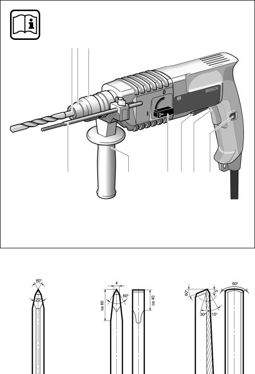
Geräteelemente
Bitte klappen Sie die Ausklappseite mit der Darstellung des Gerätes auf, und lassen Sie diese Seite aufgeklappt, während Sie die Bedienungsanleitung lesen.
Die Nummerierung der Geräteelemente bezieht sich auf die Darstellung des Gerätes auf der Grafikseite.
1Werkzeugaufnahme (SDS-plus)
2Staubschutzkappe
3Verriegelungshülse
4Tiefenanschlag
5Zusatzgriff
6Betriebsarten-Wahlschalter
7Rechts-Linkslauf-Schalter (GBH 2-20 SRE)
8Ein-Aus-Schalter
9Feststellknopf
10Zahnkranz-Bohrfutter*
11SDS-plus-Bohrfutterschaft*
12SDS-plus-Adapter*
13Flügelschraube Zusatzgriff
14Flügelschraube Tiefenanschlag
*Abgebildetes oder beschriebenes Zubehör gehört teilweise nicht zum Lieferumfang.
1 619 929 348 • (03.12) T |
Deutsch–1 |

Zu Ihrer Sicherheit
Gefahrloses Arbeiten mit dem Gerät ist nur möglich, wenn Sie die Bedienungsanleitung und die Sicherheitshinweise vollständig lesen und die darin enthaltenen Anweisungen strikt befolgen.
Zusätzlich müssen die allgemeinen Sicherheitshinweise im beigefügten Heft befolgt werden.
Lassen Sie sich vor dem ersten Gebrauch praktisch einweisen.
Zur Vermeidung von Gehörschäden ist ein Gehörschutz zu tragen.
Schutzbrille tragen.
Bei langen Haaren Haarschutz tragen. Nur mit eng anliegender Kleidung arbeiten.
■Wird bei der Arbeit das Netzkabel beschädigt oder durchtrennt, Kabel nicht berühren und sofort den Netzstecker ziehen. Gerät niemals mit beschädigtem Kabel benutzen.
■Geräte, die im Freien verwendet werden, über einen Fehlerstrom(FI)-Schutzschalter mit maximal 30 mA Auslösestrom anschließen. Das Gerät nicht bei Regen oder Nässe verwenden.
■Kabel immer nach hinten vom Gerät wegführen.
■Verwenden Sie geeignete Suchgeräte, um verborgene Versorgungsleitungen aufzuspüren, oder ziehen Sie die örtliche Versorgungsgesellschaft hinzu. Kontakt mit Elektroleitungen kann zu Feuer und elektrischem Schlag führen. Beschädigung einer Gasleitung kann zur Explosion führen. Eindringen in eine Wasserleitung verursacht Sachbeschädigung oder kann einen elektrischen Schlag verursachen.
■Verwenden Sie Ihr Gerät nur mit dem Zusatzgriff 5.
■Sichern Sie das Werkstück. Ein mit Spannvorrichtungen oder Schraubstock festgehaltenes Werkstück ist sicherer gehalten als mit Ihrer Hand.
■Gerät nur ausgeschaltet auf die Mutter/Schraube aufsetzen.
■Vorsicht beim Eindrehen langer Schrauben, Abrutschgefahr.
■Beim Arbeiten das Gerät immer fest mit beiden Händen halten und für einen sicheren Stand sorgen.
■Das Gerät vor dem Ablegen immer ausschalten und warten, bis das Gerät zum Stillstand gekommen ist.
■Niemals Kindern die Benutzung des Gerätes gestatten.
■Bosch kann nur dann eine einwandfreie Funktion des Gerätes zusichern, wenn das für dieses Gerät vorgesehene Original-Zubehör verwendet wird.
Werkzeug wechseln (Bild K–O)
Beim Wechseln der Werkzeuge darauf achten, dass die Staubschutzkappe 2 nicht beschädigt wird.
SDS-plus-Werkzeuge
Das SDS-plus-Werkzeug ist systembedingt frei beweglich. Dadurch entsteht beim Leerlauf eine Rundlaufabweichung, die sich beim Bohren selbsttätig zentriert. Dies hat keine Auswirkungen auf die Genauigkeit des Bohrlochs.
Einsetzen (Bild K )
Werkzeug vor dem Einsetzen reinigen und leicht fetten.
Das staubfreie Werkzeug in die Werkzeugaufnahme 1 drehend bis zum Einrasten einschieben.
Das Werkzeug verriegelt sich selbsttätig. Verriegelung durch Ziehen am Werkzeug prüfen.
Entnehmen (Bild L )
Verriegelungshülse 3 nach hinten ziehen (a), halten, und das Werkzeug entnehmen (b).
Werkzeuge ohne SDS-plus
Werkzeuge ohne SDS-plus nicht zum Hammerbohren oder Meißeln verwenden!
Um mit Werkzeugen ohne SDS-plus (z.B. Bohrer mit zylindrischem Schaft) arbeiten zu können, muss ein Bohrfutter 10 mit SDS-plus-Bohrfutterschaft 11 (Zubehör) in die Werkzeugaufnahme eingesetzt werden
(Bild M ).
Das staubfrei zusammengebaute Bohrfutter in die Werkzeugaufnahme 1 drehend bis zum Einrasten einschieben (Bild N ).
Das Werkzeug verriegelt sich selbsttätig. Verriegelung durch Ziehen am Werkzeug prüfen.
Schrauberbits (Bild O )
Für Schrauberbits SDS-plus-Adapter 12 (Zubehör) verwenden.
System-Zubehör
Zugehörige Einsatzwerkzeuge siehe Bosch-Katalog. Eine Zubehörauflistung finden Sie am Ende dieser Anleitung.
Inbetriebnahme
Netzspannung beachten!
Die Spannung der Stromquelle muss mit den Angaben auf dem Typenschild des Gerätes übereinstimmen. Mit 230 V gekennzeichnete Geräte können auch an 220 V betrieben werden.
Zur Inbetriebnahme des Gerätes den Ein-Aus- Schalter 8 drücken.
Zum Feststellen den Ein-Aus-Schalter 8 in gedrücktem Zustand mit dem Feststellknopf 9 arretieren.
Zum Ausschalten des Gerätes den Ein-Aus-Schalter 8 loslassen bzw. drücken und loslassen.
1 619 929 348 • (03.12) T |
Deutsch–2 |

Arbeitshinweise (Bild P–R)
Zusatzgriff (Bild P )
■Das Gerät darf aus Sicherheitsgründen nur mit dem Zusatzgriff 5 verwendet werden.
Durch Schwenken des Zusatzgriffes 5 wird eine ermüdungsfreiere und dadurch sichere Körperhaltung erreicht.
Flügelschraube 13 am Zusatzgriff 5 lockern. Griff schwenken. Flügelschraube wieder festziehen.
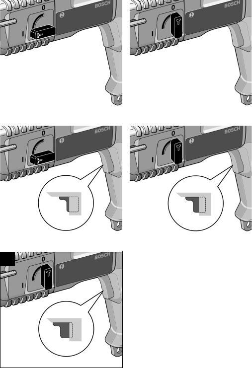
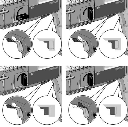
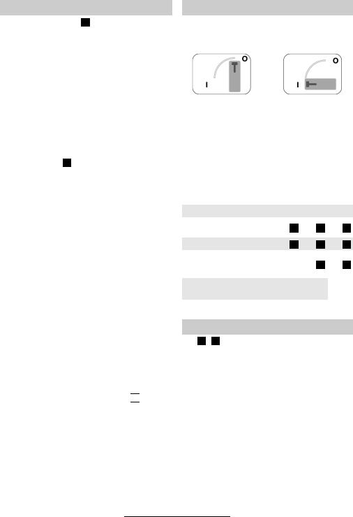
Betriebsarten (Bild A–I)
Am Betriebsarten-Wahlschalter 6 wird der Getriebezustand für den jeweiligen Anwendungsfall eingestellt:
Bohren |
Hammerbohren |
Überlastkupplung
Klemmt oder hakt das Bohrwerkzeug, wird der Antrieb zur Bohrspindel unterbrochen. Wegen der dabei auftretenden Kräfte das Gerät immer mit beiden Händen sicher halten und einen festen Stand einnehmen.
Tiefenanschlag (Bild Q )
Flügelschraube 14 am Zusatzgriff 5 lockern. Bohrtiefe t am Tiefenanschlag 4 einstellen. Flügelschraube wieder festziehen.
Staubabsaugung/Saugfix
■Beim Arbeiten entstehende Stäube können gesundheitsschädlich, brennbar oder explosiv sein. Geeignete Schutzmaßnahmen sind erforderlich.
Zum Beispiel: Manche Stäube gelten als Krebs erregend. Geeignete Staub-/Späneabsaugung verwenden und Staubschutzmaske tragen.
■Leichtmetallstaub kann brennen oder explodieren. Arbeitsplatz stets sauber halten, weil Materialmischungen besonders gefährlich sind.
Das Gerät kann direkt an der Steckdose eines Bosch Allzwecksaugers mit Fernstarteinrichtung angeschlossen werden. Dieser wird beim Einschalten des Gerätes automatisch gestartet.
Saugfix (Zubehör) montieren und Staubsauger anschließen.
Bis zur vorbestimmten Bohrtiefe federt der Saugfix zurück. Dadurch wird der Saugfix-Kopf immer dicht an der Oberfläche gehalten.
Drehzahl einstellen
(GBH 2-20 SE/GBH 2-20 SRE) (Bild  )
)
Durch zuoder abnehmenden Druck auf den Ein-Aus- Schalter 8 kann die Drehzahl während des Betriebs stufenlos gesteuert werden.
Vorteile:
–langsames Anbohren, z.B. auf glatten Flächen wie Fliesen,
–kein Abrutschen des Bohrers beim Anbohren,
–kein Aussplittern des Bohrlochs.
Die Drehzahl muss je nach Betriebsart, zu bearbeitendem Material und entsprechend dem Bohrdurchmesser ausgewählt werden.
Richtwerte dazu siehe Betriebsarten.
Der Betriebsarten-Wahlschalter darf nur im Stillstand betätigt werden.
Werkzeuge ohne SDS-plus nicht zum Hammerbohren oder Meißeln verwenden!
Die folgende Tabelle zeigt, wie der BetriebsartenWahlschalter 6, der Rechts-Linkslauf-Schalter 7 (GBH 2-20 SRE) sowie der Ein-Aus-Schalter 8 zur Regelung der Drehzahl (GBH 2-20 SE/GBH 2-20 SRE) für die verschiedenen Betriebsarten einzustellen sind (Bilder siehe Klappseite):
Betriebsart |
|
Typ GBH 2-20 |
||||||
|
S |
SE |
SRE |
|||||
Hammerbohren |
Bild |
|
Bild |
|
|
Bild |
|
|
A |
C |
|
F |
|
||||
in Beton oder Stein |
|
|
||||||
|
|
|
|
|
|
|
|
|
Bohren in Stahl oder Holz |
Bild |
B |
|
Schrauben |
|
|
|
Rechtslauf |
– |
||
Linkslauf |
– |
||
Meißeln |
Bild |
|
|
A |
|||
nur mit MV 200 (Zubehör) |
|||
|
|
||
Bild D Bild G
Bild E Bild H
–Bild I
Bild C Bild F
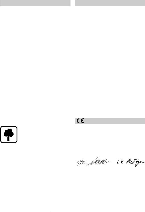
Schärfen der Meißelwerkzeuge
(Bild S – U )
Mit scharfen Einsatzwerkzeugen erzielt man gute Arbeitsleistungen und hohe Standzeiten. Deshalb Meißel rechtzeitig schärfen.
Werkzeuge an Schleifscheiben (z.B. Edelkorund) unter gleichbleibender Wasserzufuhr schleifen.
Darauf achten, dass sich an den Schneiden keine Anlassfarben zeigen, da sonst die Härte der Einsatzwerkzeuge beeinträchtigt wird.
1 619 929 348 • (03.12) T |
Deutsch–3 |
Wartung und Reinigung
■Vor allen Arbeiten am Gerät Netzstecker ziehen.
■Gerät und Lüftungsschlitze stets sauber halten, um gut und sicher zu arbeiten.
Werkzeugaufnahme täglich säubern.
Staubschutzkappe auswechseln
Beschädigte Staubschutzkappe rechtzeitig auswechseln, da Staub, der in die Werkzeugaufnahme eindringt, zu Funktionsstörungen führt.
Es wird empfohlen, dies von einem Kundendienst vornehmen zu lassen.
Sollte das Gerät trotz sorgfältiger Herstellund Prüfverfahren einmal ausfallen, ist die Reparatur von einer autorisierten Kundendienststelle für Bosch-Elektro- werkzeuge ausführen zu lassen.
Bei allen Rückfragen und Ersatzteilbestellungen bitte unbedingt die 10-stellige Bestellnummer laut Typenschild des Gerätes angeben.
Service und Kundenberater
Explosionszeichnungen und Informationen zu Ersatzteilen finden Sie unter: www.bosch-pt.com.
www.powertool-portal.de, das Internetportal für Handwerker und Heimwerker
www.ewbc.de, der Informationspool für Handwerk und Ausbildung
Deutschland
Robert Bosch GmbH
Servicezentrum Elektrowerkzeuge
Zur Luhne 2
37589 Kalefeld
Service:. . . . . . . . . . . . . . . . . . . 01 80/3 35 54 99
Fax . . . . . . . . . . . . . . . . . . . + 49 (0) 55 53/20 22 37
Kundenberater: . . . . . . . . . . . . . 01 80/3 33 57 99
Österreich
ABE Service GmbH Jochen-Rindt-Straße 1 1232 Wien
Service:. . . . . . . . . . . . . . . . . . +43 (0)1/61 03 80 Fax . . . . . . . . . . . . . . . . . . . . . +43 (0)1/61 03 84 91Kundenberater: . . . . . . . . +43 (0)1/7 97 22 30 66 E-Mail: abe@abe-service.co.at
Schweiz
Service:. . . . . . . . . . . . . . . . . +41 (0)1/847 16 16
Fax . . . . . . . . . . . . . . . . . . . . . . +41 (0)1/847 16 57
Kundenberater . . . . . . . . . . . . . . 0 800 55 11 55
Umweltschutz |
Konformitätserklärung |
|
|
Rohstoffrückgewinnung statt Müllentsorgung
Gerät, Zubehör und Verpackung sollten einer umweltgerechten Wiederverwertung zugeführt werden.
Diese Anleitung ist aus chlorfrei gefertigtem RecyclingPapier hergestellt.
Zum sortenreinen Recycling sind Kunststoffteile gekennzeichnet.
In Deutschland können nicht mehr gebrauchsfähige Geräte zum Recycling beim Handel abgegeben oder (ausreichend frankiert) direkt eingeschickt werden an:
Recyclingzentrum Elektrowerkzeuge
Osteroder Landstr. 3
37589 Kalefeld
Wir erklären in alleiniger Verantwortung, dass dieses Produkt mit den folgenden Normen oder normativen Dokumenten übereinstimmt:
EN 50 144 gemäß den Bestimmungen der Richtlinien 89/336/EWG, 98/37/EG.
Dr. Egbert Schneider |
Dr. Eckerhard Strötgen |
Senior Vice President |
Head of Product |
Engineering |
Certification |
Robert Bosch GmbH, Geschäftsbereich Elektrowerkzeuge
Änderungen vorbehalten
1 619 929 348 • (03.12) T |
Deutsch–4 |

Product Specifications
Rotary Hammer |
|
GBH 2-20 S |
GBH 2-20 SE |
GBH 2-20 SRE |
||||||
|
|
PROFESSIONAL |
PROFESSIONAL |
PROFESSIONAL |
||||||
|
|
|
|
|
|
|
|
|
|
|
Order number |
|
0 611 234 0.. |
0 611 234 6.. |
0 611 234 7.. |
||||||
Speed control |
|
– |
● |
● |
||||||
|
|
|
|
|
|
|
|
|
|
|
Right/Left rotation |
|
– |
– |
● |
||||||
Rated input power |
[W] |
500 |
500 |
500 |
||||||
|
|
|
|
|
|
|
|
|
|
|
Power output |
[W] |
300 |
300 |
300 |
||||||
Impact rate |
[per min] |
3900 |
0 … 3900 |
0 … 3900 |
||||||
|
|
|
|
|
|
|
|
|
|
|
Impact energy per stroke |
[J] |
1.5 |
1.5 |
1.5 |
||||||
Nominal speed |
[RPM] |
850 |
0 … 850 |
0 … 850 |
||||||
|
|
|
|
|
|
|
|
|
|
|
Tool holder SDS-plus |
|
● |
● |
● |
||||||
Spindle collar diameter |
[mm] |
43 (Euro-Standard) 43 (Euro-Standard) 43 (Euro-Standard) |
||||||||
|
|
|
|
|
|
|
|
|
|
|
Maximum drill diameter: |
|
|
|
|
|
|
|
|
|
|
Concrete |
[mm] |
20 |
20 |
20 |
||||||
Wood |
[mm] |
30 |
30 |
30 |
||||||
Steel |
[mm] |
13 |
13 |
13 |
||||||
Weight (without accessories) approx. |
[kg] |
2.3 |
2.3 |
2.3 |
||||||
|
|
|
|
|
|
|
|
|
|
|
Degree of protection |
|
|
|
/ II |
|
|
/ II |
|
|
/ II |
|
|
|
|
|
||||||
|
|
|
|
|
|
|
|
|
|
|
The specifications apply for the rated voltage of [U] 230/240 V. For lower voltages and with models for specific countries, the specifications can vary.
Please take note of the order number of your machine since the trade name of the individual machines can vary.
Noise/Vibration Information
Measured values determined according to EN 50 144.
Typically, the A-weighted noise levels of the tool are: Sound pressure level: 88 dB(A)
Sound power level: 101 dB(A)
Wear ear protection!
The typically weighted acceleration is 11 m/s2.
Intended Use
The machine is intended for hammer drilling in concrete, brick and stone. It is also suitable for drilling without impact in wood, metal, ceramic and plastic.
Machines with electronic control and right/left rotation are also suitable for screw driving and thread cutting.
Product Elements
Please open the foldout page with the illustration of the tool and leave it open while you read these operating instructions.
The numbering of the machine elements refers to the illustration of the machine on the graphic page.
1Tool holder (SDS-plus)
2Dust protection cap
3Locking sleeve
4Depth stop
5Auxiliary handle
6Operational mode selection switch
7Right/Left rotation switch (GBH 2-20 SRE)
8On/off switch
9Locking button
10Ring gear drill chuck*
11SDS-plus drill chuck shaft*
12SDS-plus adapter*
13Winged screw, auxiliary handle
14Winged screw, depth stop
*Not all the accessories illustrated or described are included in standard delivery.
1 619 929 348 • (03.12) T |
English–1 |
|
|
For Your Safety |
|
Tool Changing (Fig. K–O) |
|
|
|
|
|
Working safely with this machine is possible only when the operating and safety information are read completely and the instructions contained therein are strictly followed.
In addition, the general safety notes in the enclosed booklet must be observed.
Before using for the first time, ask for a practical demonstration.
Wear ear protection to prevent damage to your hearing.
Wear safety glasses.
For long hair, wear hair protection.
Work only with close-fitting clothes.
■If the cable is damaged or cut through while working, do not touch the cable but immediately pull the mains plug. Never use the machine with a damaged cable.
■Connect machines that are used in the open via a residual current device (RCD) with an actuating current of 30 mA maximum. Do not operate the machine in rain or moisture.
■Always direct the cable to the rear away from the machine.
■Use suitable detectors to find hidden utility lines or call the local utility company for assistance. Contact with electric lines can lead to fire or electrical shock. Damaging a gas line can result in an explosion. Penetrating a water pipe will cause property damage or an electrical shock.
■Operate the machine only with the auxiliary handle
5.
■Secure the workpiece. A workpiece clamped with clamping devices or in a vice is held more secure than by hand.
■Place the machine on the nut/screw only when switched off.
■Be careful when screwing in long screws; danger of sliding off.
■When working with the machine, always hold it firmly with both hands and provide for a secure stance.
■Always switch the machine off and wait until it has come to a standstill before placing it down.
■Never allow children to use the machine.
■Bosch is able to ensure flawless functioning of the machine only if the original accessories intended for it are used.
Take care that the dust protection cap 2 is not damaged when changing tools.
SDS-plus Tools
The SDS-plus tool is designed to be freely movable. This causes eccentricity when the machine is off-load. However, the drill automatically centres itself during operation. This does not affect drilling precision.
Inserting (Fig. K )
Clean and lightly oil the tool before inserting.
Insert the dust-free tool into the tool holder 1 with twisting until it latches.
The tool locks itself. Check the locking by pulling on the tool.
Removing (Fig. L )
Pull the locking sleeve 3 to the rear (a) and hold while removing the tool (b).
Tools without SDS-plus
Do not use tools without SDS-plus for hammer drilling or chiselling!
To work with tools without SDS-plus (e.g., drills with cylindrical shafts), a drill chuck 10 with a SDS-plus chuck shaft 11 (optional accessory) must be inserted into the tool holder (Fig. M ).
Insert the dust-free, assembled chuck into the tool holder 1 with twisting until it latches (Fig. N ).
The chuck locks itself. Check the locking by pulling on the chuck.
Srewdriver Bits (Fig. O )
For screwdriver bits, use the SDS-plus adapter 12 (optional accessory).
System Accessories
Refer to the Bosch Catalogue for insertion tools.
A list of accessories can be found at the end of these instructions.
Putting into Operation
Ensure that the mains voltage is correct!
The voltage of the power source must agree with the value given on the nameplate of the machine. Machines designated for 230 V can also be operated with 220 V.
To switch on the machine, press the on/off switch 8.
Lock the depressed on/off switch 8 by pressing the lock-on button 9.
To switch off the machine, release the on/off switch 8 or push and then release it.
1 619 929 348 • (03.12) T |
English–2 |
Working Instructions (Fig. P–R)
Auxiliary Handle (Fig. P )
■For safety reasons, the machine should be used only with the auxiliary handle 5.
By rotating the auxiliary handle 5 to a comfortable position, a fatigue-free and therefore safe working position can be achieved.
Loosen the winged screw 13 on the auxiliary handle 5. Swing the grip to a new position. Retighten the winged screw.
Overload Clutch
If the drill bit becomes jammed or caught, the drive to the drill spindle is interrupted. Because of the forces that occur as a result, always hold the machine securely with both hands and take a firm stance.
Depth Stop (Fig. Q )
Loosen the winged screw 14 on the auxiliary handle 5. Adjust the drilling depth t on the depth stop 4. Retighten the winged screw.
Dust Vacuuming/Vacuuming Attachment
■Dust produced while working can be detrimental to health, inflammable or explosive. Suitable protection measures are required.
Examples: Some dusts are considered to be carcinogenic. Use suitable dust/chip extraction and wear a dust protection mask.
■Light metal dust can burn or explode. Always keep the work place clean since material mixtures are especially dangerous.
The machine can be connected directly to the socket of a Bosch all-purpose vacuum cleaner with remote starting. The vacuum cleaner starts automatically when the machine is switched on.
Mount the vacuuming attachment (optional accessory) and connect the vacuum cleaner.
The vacuuming attachment is spring loaded up to the preselected drilling depth. In this manner, the vacuuming attachment head is always held close to the surface.
Setting the Speed
(GBH 2-20 SE/GBH 2-20 SRE) (Fig.  )
)
By increasing or decreasing the pressure on the on/off switch 8, the speed can be continuously controlled during operation.
Advantages:
–Slow starting of holes, e.g., on smooth surfaces or tiles
–No sliding off of the drill when stating the hole
–No splintering of the hole.
The speed must be selected according to the operating mode, the material to be worked and the diameter of the drill.
See Operating Modes for recommended values.
Operating Modes (Fig. A–I)
The operation of the gearbox for each application is set with the mode selection switch 6:
Drilling |
Hammer Drilling |
The operating mode selector switch may be actuated only at a standstill.
Do not use tools without SDS-plus for hammer drilling or chiselling!
The following table shows how the mode selection switch 6, and the right/left rotation switch 7 (GBH 2-20 SRE) as well as the on/off switch 8 for regulation the speed (GBH 2-20 SE/GBH 2-20 SRE) are to be set for the various operating modes (see illustrations on the fold-out page):
Operating Mode
Hammer drilling in concrete or stone
Drilling in steel or wood
Screw driving
Right rotation
Left rotation
Chiselling only with MV 200 (optional accessory)
Type GBH 2-20
S SE SRE
Fig. A Fig. C Fig. F
Fig. B Fig. D Fig. G
–Fig. E Fig. H
– |
– |
Fig. |
I |
|
|||
|
|
|
|
|
|
|
|
Fig. |
|
Fig. |
|
|
Fig. |
|
|
A |
C |
F |
|||||
|
|
|
|
|
|
|
|
Sharpening the Chiselling Tools
(Fig. S – U )
With sharpened insertion tools, one achieves good working performance and long service life. Therefore, sharpen the chisel regularly.
Sharpen the tool on a grinding wheel (e.g. alumina oxide) with constant water supply.
Take care that the cutting edge does not show signs of coloration since this affects the hardness of the tool.
1 619 929 348 • (03.12) T |
English–3 |
Maintenance and Cleaning
■Before any work on the machine itself, pull the mains plug.
■For safe and efficient working, always keep the machine and the ventilation slots clean.
Clean the tool holder daily.
Replacing the Dust Protection Cap
Damaged dust protection caps should be replaced as soon as possible since dust that enters the tool holder can cause malfunctions.
It is recommended that this be performed by customer service.
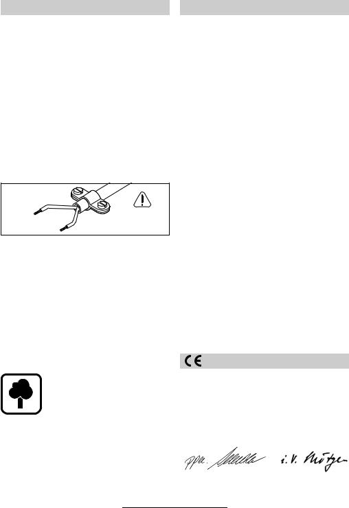
WARNING
Important instructions for connecting a new 3- pin plug to the 2-wire cable.
The wires in the cable are coloured according to the following code:
Strain relief
Live = brown
|
To be fitted |
|
by qualified |
Neutral = blue |
professionals only |
|
Do not connect the blue or brown wire to the earth terminal of the plug.
Important: If the plug on the cable of this machine must be replaced, dispose of the old plug to prevent misuse.
If the machine should fail despite the care taken in manufacture and testing, repair should be carried out by an authorised customer services agent for Bosch power-tools.
For all correspondence and spare parts orders, always include the 10-digit order number of the machine.
Service and Customer Advice
Exploded views and information on spare parts can be found under: www.bosch-pt.com.
Great Britain
Robert Bosch Ltd. (B.S.C.) P.O. Box 98
Broadwater Park
North Orbital Road
Denham-Uxbridge Middlesex UB 9 5HJ
Service . . . . . . . . . . . . . . +44 (0) 18 95/83 87 82Advice line. . . . . . . . . . . . +44 (0) 18 95/83 87 91 Fax . . . . . . . . . . . . . . . . . . . +44 (0) 18 95/83 87 89
Ireland
Beaver Distribution Ltd.
Greenhills Road
Tallaght-Dublin 24
Service . . . . . . . . . . . . . . . . + 353 (0)1/414 9400
Fax . . . . . . . . . . . . . . . . . . . . . + 353 (0)1/459 8030
Australia
Robert Bosch Australia L.t.d. RBAU/SBT2
1555 Centre Road
P.O. Box 66 Clayton
3168 Clayton/Victoria
. . . . . . . . . . . . . . . . . . . . . +61 (0)1/800 804 777 Fax . . . . . . . . . . . . . . . . . . . . +61 (0)1/800 819 520 www.bosch.com.au
E-Mail: CustomerSupportSPT@au.bosch.com
New Zealand
Robert Bosch Limited 14-16 Constellation Drive Mairangi Bay
Auckland New Zealand
. . . . . . . . . . . . . . . . . . . . . . . +64 (0)9/47 86 158 Fax . . . . . . . . . . . . . . . . . . . . . . +64 (0)9/47 82 914
Environmental Protection |
Declaration of Conformity |
|
|
Recycle raw materials instead of disposing as waste.
The machine, accessories and packaging should be submitted for environment-friendly recycling.
These instructions are printed on recycled paper manufactured without chlorine.
The plastic components are labelled for categorised recycling.
We declare under our sole responsibility that this product is in conformity with the following standards or standardization documents:
EN 50 144 according to the provisions of the directives 89/336/EEC, 98/37/EC.
Dr. Egbert Schneider |
Dr. Eckerhard Strötgen |
Senior Vice President |
Head of Product |
Engineering |
Certification |
Robert Bosch GmbH, Geschäftsbereich Elektrowerkzeuge
Specifications subject to change without notice
1 619 929 348 • (03.12) T |
English–4 |

Caractéristiques techniques
Marteau perforateur |
|
GBH 2-20 S |
GBH 2-20 SE |
GBH 2-20 SRE |
||||||
|
|
PROFESSIONAL |
PROFESSIONAL |
PROFESSIONAL |
||||||
|
|
|
|
|
|
|
|
|
|
|
Référence |
|
0 611 234 0.. |
0 611 234 6.. |
0 611 234 7.. |
||||||
Régulation de la vitesse |
|
– |
● |
● |
||||||
|
|
|
|
|
|
|
|
|
|
|
Inversion du sens de rotation |
|
– |
– |
● |
||||||
Puissance absorbée |
[W] |
500 |
500 |
500 |
||||||
|
|
|
|
|
|
|
|
|
|
|
Puissance débitée |
[W] |
300 |
300 |
300 |
||||||
Fréquence de frappe |
[min-1] |
3900 |
0 … 3900 |
0 … 3900 |
||||||
Travail par coup |
[J] |
1,5 |
1,5 |
1,5 |
||||||
Vitesse nominale |
[min-1] |
850 |
0 … 850 |
0 … 850 |
||||||
Fixation de l’outil SDS-plus |
|
● |
● |
● |
||||||
Ø Collet de broche |
[mm] |
43 (euronorme) |
43 (euronorme) |
43 (euronorme) |
||||||
|
|
|
|
|
|
|
|
|
|
|
Diamètre (max.): |
|
|
|
|
|
|
|
|
|
|
Béton |
[mm] |
20 |
20 |
20 |
||||||
Bois |
[mm] |
30 |
30 |
30 |
||||||
Acier |
[mm] |
13 |
13 |
13 |
||||||
Poids (sans accessoires) env. |
[kg] |
2,3 |
2,3 |
2,3 |
||||||
|
|
|
|
|
|
|
|
|
|
|
Classe de protection |
|
|
|
/ II |
|
|
/ II |
|
|
/ II |
|
|
|
|
|
||||||
|
|
|
|
|
|
|
|
|
|
|
Ces indications sont valables pour des tensions nominales de [U] 230/240 V. Ces indications peuvent varier pour des tensions plus basses ainsi que pour des versions spécifiques à certains pays.
Vouloir tenir compte du numéro de commande de l’appareil électroportatif. Les désignations commerciales peuvent varier selon les modèles.
Bruits et vibrations |
|
Eléments de l’appareil |
|
|
|
Valeurs de mesures obtenues conformément à la norme européenne 50 144.
Les mesures réelles (A) des niveaux acoustiques de la machine sont :
Intensité de bruit 88 dB(A). Niveau de bruit 101 dB(A).
Se munir d’une protection acoustique !
L’accélération réelle mesurée est 11 m/s2.
Utilisation conforme
L’appareil est conçu pour les travaux de perçage en frappe dans le béton, la brique ou la pierre. Il est également approprié pour le perçage sans frappe dans le bois, le métal, la céramique et les matières plastiques. Les appareils avec réglage électronique et rotation à droite/à gauche sont également appropriés pour le vissage et le filetage.
Dépliez le volet sur lequel l’appareil est représenté de manière graphique. Laissez le volet déplié pendant la lecture de la présente notice d’instructions.
La numérotation des éléments de l’appareil se rapporte aux figures représentant l’appareil sur la page des graphiques.
1Fixation de l’outil (SDS-plus)
2Capuchon anti-poussières
3Douille de verrouillage
4Butée de profondeur
5Poignée supplémentaire
6Sélecteur de mode de fonctionnement
7Commutateur de sens de rotation droite/gauche (GBH 2-20 SRE)
8Interrupteur Marche/Arrêt
9Bouton de marche permanente
10Mandrin-à clé*
11Queue pour mandrin SDS-plus*
12Adaptateur SDS-plus*
13Vis à ailettes de la poignée supplémentaire
14Vis à ailettes de la butée de profondeur
*Les accessoires reproduits ou décrits ne sont pas tous compris dans les fournitures.
1 619 929 348 • (03.12) T |
Français–1 |
Pour votre sécurité
Pour travailler sans risque avec cet appareil, lire intégralement au préalable les instructions de service et les remarques concernant la sécurité. Respecter scrupuleusement les indications et les consignes qui y sont données.
Respecter en plus les indications générales de sécurité se trouvant dans le cahier ci-joint.
Avant la première mise en service, laisser quelqu’un connaissant bien cet appareil vous instruire de la manière de s’en servir.
Pour prévenir toute atteinte à l’ouïe, porter une protection acoustique.
Porter des lunettes de protection.
Les personnes portant les cheveux longs, doivent se munir d’un protègecheveux. Ne travailler qu’avec des vêtements près du corps.
■Si le câble d’alimentation électrique est endommagé ou rompu pendant le travail, ne pas y toucher. Retirer immédiatement la fiche du câble d’alimentation de la prise électrique. Ne jamais utiliser un appareil dont le câble d’alimentation est endommagé.
■Brancher les appareils qui sont utilisés à l’extérieur sur un disjoncteur différentiel avec un courant de déclenchement maximal de 30 mA. Ne pas utiliser l’appareil par temps de pluie ni dans un endroit humide.
■Toujours ramener les câbles à l’arrière de l’appareil.
■Utiliser des détecteurs de métaux appropriés afin de localiser la présence de conduites électriques ou bien s’adresser à la société locale de distribution. Un contact avec des lignes électriques peut provoquer un incendie et une décharge électrique. Le fait d’endommager une conduite de gaz peut entraîner une explosion. Le fait d’endommager une conduite d’eau peut entraîner des dégâts matériels ou causer une décharge électrique.
■N’utiliser l’appareil qu’avec la poignée supplémentaire 5.
■Bloquer la pièce à travailler. Une pièce à travailler serrée par des dispositifs de serrage ou dans un étau est fixée de manière plus sûre que lorsqu’elle est immobilisée à la main.
■N’appliquer l’appareil sur un écrou ou une vis que lorsqu’il est à l’arrêt.
■Attention lors de la pose des vis un peu longues : elles peuvent glisser.
■Pendant le travail avec cet appareil, le tenir toujours fermement et à deux mains. Adopter une position stable et sûre.
■Avant de déposer l’appareil, toujours le mettre hors fonctionnement et attendre l’arrêt total de l’appareil.
■Ne jamais laisser des enfants utiliser cet appareil.
■Bosch ne peut garantir un fonctionnement impeccable que si les accessoires Bosch d’origine prévus pour cet appareil sont utilisés.
Changement d’outil (Fig. K–O)
En changeant d’outil, prendre garde à ne pas endommager le capuchon anti-poussières 2.
Outils SDS-plus
Une fois correctement mis en place, un outil SDS-plus peut encore librement bouger. Ceci est une caractéristique du système SDS-plus. Il en résulte un fauxrond en marche à vide qui se corrige de lui-même lors du perçage et n’affecte en rien la précision du travail.
Mise en place (Fig. K )
Avant de mettre un outil en place, le nettoyer et le graisser légèrement.
En lui imprimant un léger mouvement de rotation sur son axe, engager l’outil exempt de poussière dans la fixation d’outil 1, jusqu’à ce qu’il enclenche.
Le verrouillage de l’outil s’effectue de manière automatique. Contrôler qu’il est bien verrouillé en position de travail en tirant dessus.
Enlèvement de l’outil (Fig. L )
Tirer la douille de verrouillage 3 vers l’arrière (a), la maintenir dans cette position et retirer l’outil (b).
Outils sans SDS-plus
Pour perforer ou buriner, ne jamais utiliser d’outils sans SDS-plus !
Pour travailler avec des outils sans système de fixation SDS-plus (forets à queue cylindrique, par exemple), il faut mettre en place sur la fixation d’outil un mandrin 10 via une queue de fixation SDS-plus pour mandrin 11 (accessoire) (Fig. M ).
En lui imprimant un léger mouvement de rotation sur son axe, engager le mandrin monté sur la queue de fixation SDS-plus (l’ensemble étant exempt de poussières) dans la fixation d’outil 1, jusqu’à ce qu’il enclenche (Fig. N ).
Le verrouillage de l’outil s’effectue de manière automatique. Contrôler qu’il est bien verrouillé en position de travail en tirant dessus.
Embouts de vissage (Fig. O )
Pour utiliser des embouts de tournevis, avoir recours à l’adaptateur SDS-plus 12 (accessoire).
Accessoires compatibles
Pour plus de détails sur les outils utilisables avec cet appareil : cf. le catalogue Bosch.
Une liste des accessoires figure à la fin du présent manuel d’instructions.
1 619 929 348 • (03.12) T |
Français–2 |

Mise en service
Tenir compte de la tension du secteur !
La tension de la source de courant doit correspondre aux indications figurant sur la plaque signalétique de l’appareil. Les appareils fonctionnant sous 230 V peuvent également être utilisés sous 220 V.
Afin de mettre l’appareil en fonctionnement, appuyer sur l’interrupteur Marche/Arrêt 8.
Afin de bloquer l’interrupteur Marche/Arrêt 8 en position « Marche », appuyer sur le bouton de marche permanente 9.
Afin d’arrêter l’appareil, relâcher l’interrupteur Marche/Arrêt 8 ou appuyer sur l’interrupteur et le relâcher.
Conseils pratiques (Fig. P–R)
Poignée supplémentaire (Fig. P )
■Pour des raisons de sécurité, l’appareil ne doit être mis en oeuvre qu’avec la poignée supplémentaire 5.
Le pivotement de la poignée supplémentaire 5 favorise le cas échéant une position de travail moins fatiguante pour le corps, donc plus sûre.
Débloquer la vis à ailettes 13 au niveau de la poignée supplémentaire 5. Faire pivoter la poignée. Rebloquer les vis à ailettes.
Dispositif anti-surcharge à crabot
Si l’outil grippe ou bloque, l’entraînement de la broche est interrompu. En raison des forces importantes qui sont déployées lors de son utilisation, toujours tenir l’appareil électroportatif à deux mains et adopter une position de travail stable.
Butée de profondeur (Fig. Q )
Débloquer la vis à ailettes 14 au niveau de la poignée supplémentaire 5. Régler la profondeur de perçage t au niveau de la butée de profondeur 4. Rebloquer les vis à ailettes.
Aspiration de poussières/Set d’aspiration
■Les poussières produites pendant le travail peuvent être nocives, inflammables ou explosives. Prendre les mesures de protection qui s’imposent. Exemple : certaines poussières sont réputées cancérigènes. Utiliser un dispositif approprié d’aspiration des poussières et des copeaux et porter un masque anti-poussières.
■Les poussières de métaux légers peuvent brûler ou exploser. Toujours maintenir propre le poste de travail, les mélanges de matériaux étant particulièrement dangereux.
L’appareil peut être raccordé directement à la prise électrique d’un aspirateur universel Bosch équipé d’un dispositif de démarrage à distance. Ce dispositif lance automatiquement l’aspirateur à chaque fois que l’appareil qui lui est raccordé est mis en marche.
Monter le set d’aspiration avec tuyau souple (accessoire) sur l’appareil et raccorder l’aspirateur.
Montée sur ressort, la tête du set d’aspiration recule progressivement avec l’avance de l’outil dans la paroi, jusqu’à la profondeur de perçage préalablement définie. Elle reste ainsi toujours au plus près de la surface.
Réglage de la vitesse de rotation (GBH 2-20 SE/GBH 2-20 SRE) (Fig.  )
)
Le fait d’exercer une pression plus ou moins forte sur l’interrupteur Marche/Arrêt 8 permet d’ajuster en continu pendant le travail la vitesse de rotation de l’outil.
Avantages :
–Amorces de perçage plus lentes et donc mieux contrôlées (sur surfaces lisses : carrelages, par exemple).
–Pas de dérapage du foret lors des amorces de trous.
–Pas de fissuration ou d’éclatement du trous de perçage.
La vitesse de rotation doit être choisie en fonction du mode de fonctionnement sélectionné, du matériau travaillé et du diamètre de l’outil.
Pour quelques valeurs indicatives, cf. chapitre mode de fonctionnement.
Modes de fonctionnement (Fig. A–I)
Le sélecteur de mode de fonctionnement 6 permet de sélectionner la configuration de l’entraînement convenant le mieux à l’application couramment envisagée :
Perçage |
Rotation vers la gauche |
Le sélecteur de mode de fonctionnement ne doit être activé que lorsque l’outillage est hors marche.
Pour perforer ou buriner, ne jamais utiliser d’outils sans SDS-plus !
1 619 929 348 • (03.12) T |
Français–3 |

Le tableau suivant précise la manière dont le sélecteur de modes de fonctionnement 6, le commutateur de sens de rotation 7 (GBH 2-20 SRE) et l’interrupteur Marche/Arrêt 8 doivent être mis en oeuvre, en fonction des différents modes de fonctionnement, pour faire varier la vitesse de rotation des modèles GBH 2-20 SE/GBH 2-20 SRE (cf. les figures du volet rabattant):
Mode de fonctionnement Modèle GBH 2-20
|
S |
|
|
SE |
SRE |
|||
Perforation |
Fig. |
|
|
Fig. |
|
Fig. |
|
|
A |
|
C |
F |
|
||||
du béton et de la pierre |
|
|
||||||
|
|
|
|
|
|
|
|
|
|
|
|
|
|
|
|
|
|
Perçage dans l’acier |
Fig. |
|
|
Fig. |
|
Fig. |
|
|
B |
|
D |
G |
|
||||
ou le bois |
|
|
||||||
|
|
|
|
|
|
|
|
|
Vissage |
|
|
|
|
|
|
|
|
Rotation vers la droite |
– |
|
|
Fig. |
E |
Fig. |
H |
|
Rotation vers la gauche |
– |
|
|
– |
|
Fig. |
|
|
|
|
|
I |
|
||||
|
|
|
|
|
|
|
|
|
Burinage : seulement |
Fig. |
|
|
Fig. |
|
Fig. |
|
|
A |
|
C |
F |
|
||||
avec MV 200 (accessoire) |
|
|
||||||
|
|
|
|
|
|
|
|
|
|
|
|
|
|
|
|
|
|
Affûtage des outils de burinage
(Fig. S – U )
Les meilleures performances et les meilleures durées de vie s’obtiennent avec des outils parfaitement affûtés. Il convient donc de réaffûter ses burins à temps.
Meuler l’outil sur un tour en veillant à ce qu’un filet d’eau régulier refroidisse l’ensemble.
Veiller à ce qu’aucune couleur n’apparaisse au niveau des tranchants. Cela signifierait que la dureté de l’outil est entamée.
Maintenance et nettoyage
■Avant toute intervention sur l’appareil, toujours retirer la fiche du câble d’alimentation de la prise électrique.
■Pour obtenir un travail satisfaisant et sûr, nettoyer régulièrement l’appareil ainsi que ses ouïes de refroidissement.
Nettoyer quotidiennement la fixation de l’outil.
Remplacement du capuchon anti-poussières
Un capuchon anti-poussières endommagé doit être remplacé à temps afin que la poussière ne puisse pénétrer dans la fixation d’outil et ainsi menacer le bon fonctionnement de l’appareil.
Il est recommandé de confier cette intervention à un centre de service agréé.
Si, malgré tous les soins apportés à la fabrication et au contrôle de l’appareil, celui-ci devait avoir un défaut, la réparation ne doit être confiée qu’à une station de service après-vente pour outillage Bosch agréée.
Pour toute demande de renseignement ou commande de pièces de rechange, nous préciser impérativement le numéro de référence à dix chiffres de la machine.
Instructions de protection de l’environnement
Récupération des matières premières plutôt qu’élimination des déchets
Les machines, comme d’ailleurs leurs accessoires et emballages, doivent pouvoir suivre chacun une voie de recyclage appropriée.
Ce manuel d’instructions a été fabriqué à partir d’un papier recyclé blanchi en l’absence de chlore.
De même, nos pièces plastiques ont été marquées en vue d’un recyclage sélectif des différents matériaux.
Service Après-Vente
Vous trouverez des vues éclatées ainsi que des informations concernant les pièces de rechange sous : www.bosch-pt.com.
France
Information par Minitel 11
Nom : Bosch Outillage
Localité : Saint Ouen
Département : 93
Robert Bosch France S.A.
Service Après-vente Outillage
B.P. 67-50, Rue Ardoin
93402 St. Ouen Cedex
Service conseil client . . . . . . . . . . . 0143 11 90 02 Numéro Vert . . . . . . . . . . . . . . . . . 0800 05 50 51
Belgique
. . . . . . . . . . . . . . . . . . . . . . . +32 (0)2/525 51 43 Fax . . . . . . . . . . . . . . . . . . . . . . +32 (0)2/525 54 20 E-mail: Outillage.Gereedschappen@be.bosch.com
Suisse
. . . . . . . . . . . . . . . . . . . . . . . +41 (0)1/847 16 16 Fax . . . . . . . . . . . . . . . . . . . . . . +41 (0)1/847 16 57
Service conseil client . . . . . . . . . . 0 800 55 11 55
Déclaration de conformité
Nous déclarons sous notre propre responsabilité que ce produit est en conformité avec les normes ou documents normalisés :
EN 50 144 conformément aux termes des réglementations 89/336/CEE, 98/37/CE.
Dr. Egbert Schneider |
Dr. Eckerhard Strötgen |
Senior Vice President |
Head of Product |
Engineering |
Certification |
Robert Bosch GmbH, Geschäftsbereich Elektrowerkzeuge
Sous réserve de modifications
1 619 929 348 • (03.12) T |
Français–4 |

Características técnicas
Martillo perforador |
|
GBH 2-20 S |
GBH 2-20 SE |
GBH 2-20 SRE |
||||||
|
|
PROFESSIONAL |
PROFESSIONAL |
PROFESSIONAL |
||||||
|
|
|
|
|
|
|
|
|
|
|
Número de pedido |
|
0 611 234 0.. |
0 611 234 6.. |
0 611 234 7.. |
||||||
Control de revoluciones |
|
– |
● |
● |
||||||
|
|
|
|
|
|
|
|
|
|
|
Giro derecha/izq. |
|
– |
– |
● |
||||||
Potencia absorbida nominal |
[W] |
500 |
500 |
500 |
||||||
|
|
|
|
|
|
|
|
|
|
|
Potencia útil |
[W] |
300 |
300 |
300 |
||||||
Número de percusiones |
[min-1] |
3900 |
0 … 3900 |
0 … 3900 |
||||||
Energía por percusión |
[J] |
1,5 |
1,5 |
1,5 |
||||||
Revoluciones nominales |
[min-1] |
850 |
0 … 850 |
0 … 850 |
||||||
Porta útiles SDS-plus |
|
● |
● |
● |
||||||
Ø Cuello del husillo |
[mm] |
43 (Norma Euro) |
43 (Norma Euro) |
43 (Norma Euro) |
||||||
|
|
|
|
|
|
|
|
|
|
|
Diámetro de taladro máx. en: |
|
|
|
|
|
|
|
|
|
|
Hormigón |
[mm] |
20 |
20 |
20 |
||||||
Madera |
[mm] |
30 |
30 |
30 |
||||||
Acero |
[mm] |
13 |
13 |
13 |
||||||
Peso (sin acc.) aprox. |
[kg] |
2,3 |
2,3 |
2,3 |
||||||
|
|
|
|
|
|
|
|
|
|
|
Clase de protección |
|
|
|
/ II |
|
|
/ II |
|
|
/ II |
|
|
|
|
|
||||||
|
|
|
|
|
|
|
|
|
|
|
Estos datos son válidos para tensiones nominales de [U] 230/240 V. Los valores pueden variar si la tensión fuese inferior, y en las ejecuciones específicas para ciertos países.
Preste atención al nº de pedido de su aparato, ya que las denominaciones comerciales de algunos aparatos pueden variar.
Información sobre ruido y vibraciones
Determinación de los valores de medición según norma EN 50 144.
El nivel de ruido típico del aparato determinado con un filtro A corresponde a:
Nivel de presión de sonido 88 dB(A). Nivel de potencia acústica 101 dB(A).
¡Usar protectores auditivos!
La aceleración típica corresponde a 11 m/s2.
Utilización reglamentaria
El aparato ha sido proyectado para taladrar con percusión en hormigón, ladrillo y piedra. Además es adecuado también para taladrar sin percutir en madera, metal, cerámica y materiales sintéticos.
Los aparatos regulados electrónicamente, con inversión del sentido de giro, son adecuados además para atornillar y para tallar roscas.
Elementos del aparato
Despliegue la solapa con la representación del aparato y manténgala abierta mientras lee estas instrucciones de manejo.
La numeración de los elementos del aparato está referida a su imagen en la página ilustrada.
1Portaútiles (SDS-plus)
2Caperuza antipolvo
3Casquillo de enclavamiento
4Tope de profundidad
5Empuñadura adicional
6Selector del modo de operación
7Conmutador de inversión de giro (GBH 2-20 SRE)
8Interruptor de conexión/desconexión
9Botón de enclavamiento
10Portabrocas de corona dentada*
11Vástago de portabrocas SDS-plus*
12Adaptador SDS-plus*
13Tornillo de mariposa para empuñadura adicional
14Tornillo de mariposa para tope de profundidad
*Los accesorios ilustrados o descritos pueden no corresponder al material suministrado de serie con el aparato.
1 619 929 348 • (03.12) T |
Español–1 |
|
|
Para su seguridad |
|
Cambio del útil (fig. K–O) |
|
|
|
|
|
Vd. solamente puede trabajar sin peligro con el aparato si lee íntegramente las instrucciones de manejo y las indicaciones de seguridad, ateniéndose estrictamente a las indicaciones allí comprendidas. Adicionalmente deberán respetarse las instrucciones de seguridad generales comprendidas en el folleto adjunto.
Déjese instruir prácticamente en el manejo antes de su primer empleo.
Para evitar daños auditivos debe utilizarse un protector de oídos.
Llevar gafas de protección.
Si lleva el pelo largo, recójaselo bajo una protección adecuada. Trabajar únicamente con vestimenta ceñida al cuerpo.
■Si llega a dañarse o cortarse el cable de red durante el trabajo, no tocar el cable, sino extraer inmediatamente el enchufe de red. No usar jamás el aparato con un cable deteriorado.
■Conectar los aparatos utilizados en la intemperie a través de un fusible diferencial con una corriente de disparo máxima de 30 mA. No exponer el aparato a la lluvia o humedad.
■Mantener el cable siempre detrás del aparato.
■Utilice unos aparatos de exploración adecuados para detectar posibles conductores o tuberías ocultas, o consulte a sus compañías abastecedoras locales. El contacto con conductores eléctricos puede provocar una descarga eléctrica e incluso un incendio. Al dañar una tubería de gas puede producirse una explosión. La perforación de una tubería de agua pueden causar daños materiales o una descarga eléctrica.
■Solamente emplee el aparato con la empuñadura adicional 5.
■Asegure la pieza de trabajo. Una pieza de trabajo fijada con unos dispositivos de sujeción, o en un tornillo de banco, se mantiene sujeta de forma mucho más segura que con la mano.
■Aplicar solamente el aparato desconectado sobre la tuerca/tornillo.
■Cuidado al enroscar tornillos largos por existir peligro de resbalar.
■Trabajar con el aparato sujetándolo siempre fuertemente con ambas manos y manteniendo una posición estable.
■Siempre desconectar y esperar a que se detenga el aparato, antes de depositarlo.
■Jamás permita que niños utilicen el aparato.
■Bosch solamente puede garantizar el funcionamiento correcto del aparato si se utilizan los accesorios originales previstos.
Al cambiar de útil, cuidar de no dañar la caperuza antipolvo 2.
Utiles SDS-plus
Condicionado por el sistema, el útil SDS-plus se mueve libremente. Por ello, al funcionar en vacío, el útil puede girar con cierta excentricidad, la cual se elimina al taladrar, gracias a su efecto autocentrante. Esto no afecta en absoluto a la exactitud de la perforación.
Inserción (fig. K )
Limpiar y engrasar ligeramente el útil antes de su inserción.
Introducir girando el útil libre de polvo en el portaútiles 1 y empujarlo hasta que engatille. El útil queda enclavado automáticamente.
Comprobar su correcta sujeción tirando del útil.
Extracción (fig. L )
Desplazar el casquillo de enclavamiento 3 hacia atrás
(a), mantenerlo en esa posición y extraer el útil (b).
Utiles sin SDS-plus
¡No emplear útiles sin SDS-plus para taladrar con percusión o cincelar!
Para poder trabajar con útiles sin SDS-plus (p.ej. brocas de vástago cilíndrico) debe montarse en el portaútiles un portabrocas 10 junto con un adaptador SDSplus para portabrocas 11 (accesorio) (fig. M ).
Insertar el portabrocas completado y libre de polvo girándolo en el portaútiles 1 y empujarlo hasta quedar enclavado (fig. N ).
El útil se bloquea por sí mismo. Verificar su enclavamiento tirando del útil.
Láminas de destornillador (fig. O )
Para montar láminas de destornillador se requiere el adaptador SDS-plus 12 (accesorio especial).
Sistema de accesorios
Los útiles adaptables correspondientes se detallan en el catálogo Bosch.
Una lista de accesorios la encuentra al final de estas instrucciones.
Puesta en funcionamiento
¡Cerciorarse de que la tensión de la red sea correcta!
La tensión de la fuente de energía debe coincidir con las indicaciones en la placa de características del aparato. Los aparatos marcados con 230 V pueden funcionar también a 220 V.
Para la puesta en marcha del aparato presionar el interruptor de conexión/desconexión 8.
Para enclavar el interruptor de conexión/desconexión 8 mantenerlo apretado, y presionar el botón de enclavamiento 9.
Para desconectar el aparato soltar, o presionar y soltar si estuviese enclavado, el interruptor de conexión/ desconexión 8.
1 619 929 348 • (03.12) T |
Español–2 |
 Loading...