


 Loading...
Bosch FAH-440, FAP-440-D, FAP-440-DT, FAP-440-DTC, FAP-440 Installation Manual
...Analog Detectors and Bases
FAP-440/FAH-440 Detector Series | FAA-440 Base Series
|
|
|
|
|
|
|
|
|
|
|
|
|
|
|
en |
Installation Guide |
pt |
Manual de Instalação |
|
es |
Manual de instalación |
th |
|
|

FAP-440/FAH-440 Detector Series | FAA-440 Base Series |
3 |
|
|
en |
Installation Guide |
5 |
|
|
|
es |
Manual de instalación |
13 |
|
|
|
pt |
Manual de Instalação |
22 |
th |
|
|
|
31 |
Bosch Security Systems, Inc. |
F.01U.123.589 | 5.0 | 2012.02 |

4 |
FAP-440/FAH-440 Detector Series | FAA-440 Base Series |
|
|
F.01U.123.589 | 5.0 | 2012.02 |
Bosch Security Systems, Inc. |

Analog Detectors and Bases |
Table of Contents | en |
5 |
|
|
|
Table of Contents
1 |
Notes |
6 |
|
|
|
2 |
Product Types |
6 |
|
|
|
3 |
Mounting |
7 |
3.1 |
Mounting the Detector |
7 |
3.2 |
Locking and Releasing the Detector |
7 |
|
|
|
4 |
Wiring and Addressing Information |
8 |
4.1 |
Wiring Information |
8 |
4.2 |
Addressing Information |
10 |
|
|
|
5 |
Testing the Installation |
10 |
5.1 |
Magnet Switch Test |
10 |
5.2 |
Functional Testing |
11 |
|
|
|
6 |
Specifications |
12 |
Bosch Security Systems, Inc. |
Installation Guide |
F.01U.123.589 | 5.0 | 2012.02 |
6 en | Notes Analog Detectors and Bases
1 Notes
This document covers mounting and wiring for the FAP-440 Series bases and detector heads.
For proper installation, read and understand NFPA-72, The National Fire Alarm Code before installation.
|
NOTICE! |
|
Any information on operation and maintenance of the devices is described in the Operation |
|
Guide F.01U.173.498, which is available for download at www.boschsecurity.us. |
|
|
|
|
|
NOTICE! |
|
Install the device according to this Installation Guide, NFPA 72, Local Codes and the Authority |
|
Having Jurisdiction (AHJ). Failure to follow these procedures may cause the device to not |
|
function properly. Bosch Security Systems is not responsible for any devices that are |
|
improperly installed. |
|
|
|
|
|
CAUTION! |
|
Do not paint the detectors. Paint or other foreign matter can prohibit detection. |
|
|
|
|
|
CAUTION! |
|
Do not remove the dust cap until all onsite construction work has been completed and the fire |
|
panel network has been commissioned. |
|
|
2 |
Product Types |
|
|
Product Type |
Description |
FAP-440 |
Analog Photoelectric Detector |
FAP-440-D |
Analog Dual-Photoelectric Detector |
FAP-440-T |
Analog Multisensor Detector Photo/Heat |
FAP-440-DT |
Analog Multisensor Detector Dual-Photo/Heat |
FAP-440-TC |
Analog Multicriteria Detector Photo/Heat/CO |
FAP-440-DTC |
Analog Multicriteria Detector Dual-Photo/Heat/CO |
FAH-440 |
Analog Heat Detector, configurable fixed temperature/rate-of-rise |
FAA-440-B4 |
Analog Standard Base 4 inches |
FAA-440-B6 |
Analog Standard Base 6 inches |
FAA-440-B4-ISO |
Analog Isolator Base 4 inches |
FAA-440-B6-ISO |
Analog Isolator Base 6 inches |
Table 2.1 List of Products
NOTICE!
The CO sensor detects carbon monoxide as a by-product of combustion. It has not been evaluated for its ability to detect hazardous CO gas. Do not use the FAP-440-TC and FAP-440-DTC as stand-alone CO detector.
WARNING!
The FAH-440 heat detectors are not life safety devices.
F.01U.123.589 | 5.0 | 2012.02 |
Installation Guide |
Bosch Security Systems, Inc. |
Analog Detectors and Bases Mounting | en 7
3 Mounting
NOTICE!
Smoke detectors are not to be used with detector guards unless the combination has been evaluated and found suitable for that purpose.
–Follow NFPA-72 guidelines for mounting locations. For commercial and industrial installations, 30 ft. (9 m) spacing between smoke detectors is recommended.
–The electrical boxes must be large enough to accommodate the number and size of conductors as specified by the National Electrical Code or the local Authorities Having Jurisdiction (AHJ).
3.1 |
Mounting the Detector |
|
|
|
3 |
4
|
2 |
|
|
|
|
|
|
3 |
|
|
1 |
1 |
|
|
|
|
|
|
|
|
3 |
1 |
1 |
|
|
|
|
||
|
|
|
3 |
|
|
|
|
|
|
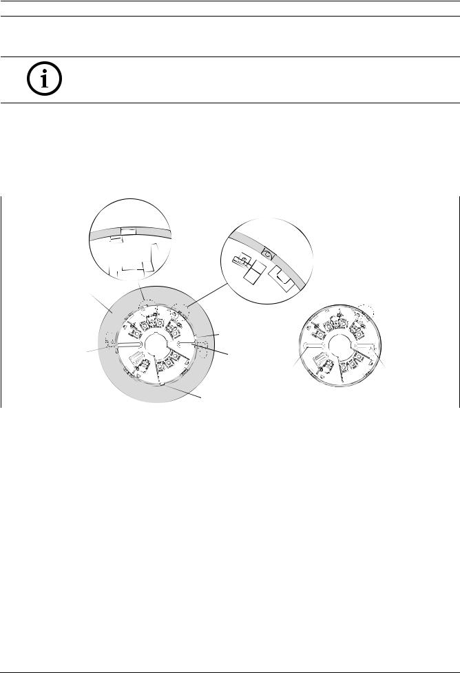
Figure 3.1 |
6-inch and 4-inch Mounting Bases |
|
|
|
|
|
|
|
|
Position |
|
Description |
|
|
1 |
|
Mounting holes |
|
|
2 |
|
Base skirt |
|
|
3 |
|
Release tabs |
|
|
4 |
|
Semicircle notch |
|
|
1.Mount the base using the two oblong mounting holes (see Figure 3.1, Position 1).
If you mount the detector with a 6-inch base, first remove the base skirt (2) from the mounting base using a screwdriver to release the 4 tabs (3).
2.Tighten the base to the mounting surface. Do not over tighten. If you use a 6-inch base, fit the base skirt onto the mounting base.
3.Turn clockwise until the detector head locks into place and aligns with the semi-circle notch (4).
3.2 |
Locking and Releasing the Detector |
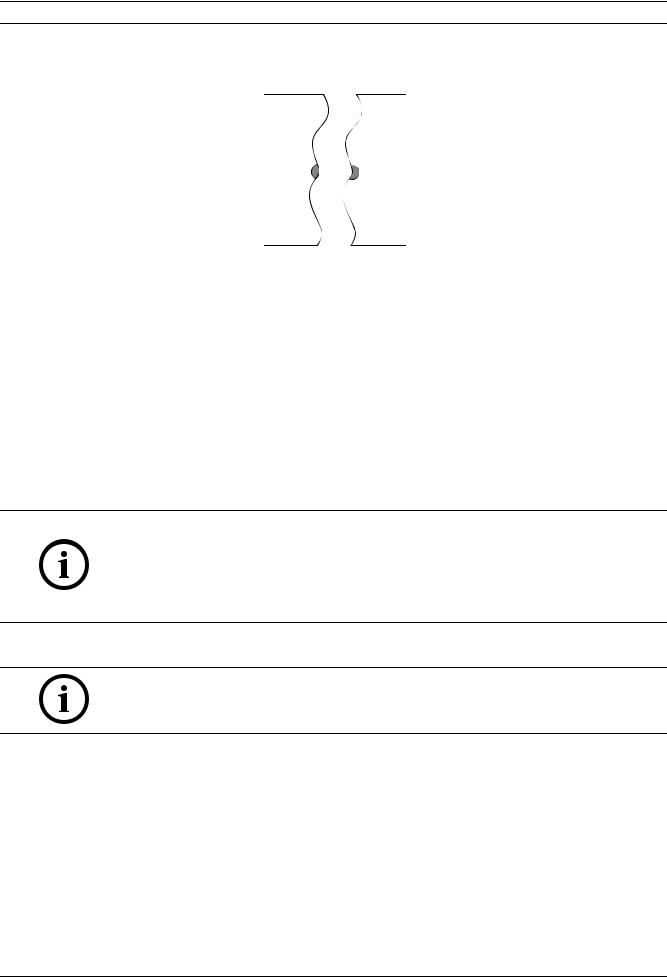
The detector bases are supplied with a snap-off locking bar (X) as part of the base moulding to prevent malicious removal of the detector. The locking mechanism is selectable and is activated by shifting the U-shaped locking bar
(X) into the position as shown in Figure 3.2.
1.Remove the U-shaped locking bar by breaking it from its holder.
2.Tuck it into the opening next to it by pushing hard.
Bosch Security Systems, Inc. |
Installation Guide |
F.01U.123.589 | 5.0 | 2012.02 |

8 |
en | Wiring and Addressing Information |
Analog Detectors and Bases |
|
|
|
3.Insert the detector head into the base.
X  X
X
Figure 3.2 Activating the Locking Mechanism
Release the locked detector head by pushing hard through the dimple (O) on the detector’s outer rim with a screwdriver (see Figure 3.3) and at the same time, turning the detector head to the left.
O
|
O |
||||
|
|
|
|
|
|
Figure 3.3 |
Releasing the Detector |
||||
4 |
Wiring and Addressing Information |
||||
4.1 |
Wiring Information |
||||
|
|
|
|
|
|
|
WARNING! |
||||
|
Do not twist or loop the wires around the terminals. In and out wires for terminal connection |
||||
|
must be cut, stripped, and inserted as individual ends. |
||||
|
|
|
|
|
|
|
|
|
|
|
|
|
|
|
|
|
|
The following wire gauges and maximum line lengths are tested and approved.
–18 AWG (0.8 mm2) -> 4000 ft (1200m)
–16 AWG (1.3 mm2) -> 6225 ft (1900m)
–14 AWG (2.1 mm2) -> 7200 ft (2200m)
–12 AWG (3.3 mm2) -> 9850 ft (3000m)
Standard non-twisted, non-shielded wiring (plain old wire) for the SLCs is recommended.
NOTICE!
Voltage drop calculations along with anticipated wire distance should be considered to ensure a voltage supply of at least 24 V at every detector.
F.01U.123.589 | 5.0 | 2012.02 |
Installation Guide |
Bosch Security Systems, Inc. |

Analog Detectors and Bases Wiring and Addressing Information | en 9
Terminal Lettering |
Terminal Function |
SC |
SLC bus - IN/OUT |
S |
SLC bus + IN/OUT |
Sin |
SLC bus + IN |
Sout |
SLC bus + OUT |
C |
Remote output |
|
|
S |
S |
|
SC |
SC |
SC |
|
S |
|
|
|
+ |
|
|
|
S |
|
|
|
C |
|
|
|
|
SC |
|
|
+ |
S |
|
|
|
|
|
Figure 4.1 |
FAA-440-B6/-B4 Standard Base Class B Wiring (Class A Wiring Indicated by Dashed Wire) |
|
|
|
|
Sout -> Sin |
Sout |
|
SC |
SC |
SC |
|
Sin |
|
|
|
+ |
|
|
n |
|
i |
|
S |
+ |
|
|
S |
|
out |
|
|
S |
+ |
C |
|
|
|
Sout |
in |
SC |
S |
|
C |
|
|
Sout |
in |
SC |
S |
|
C |
|
SC
Sout
+
Figure 4.2 FAA-440-B6-ISO/-B4-ISO Isolator Base Class B Wiring (Class A Wiring Indicated by Dashed Wire)
Bosch Security Systems, Inc. |
Installation Guide |
F.01U.123.589 | 5.0 | 2012.02 |
10 en | Testing the Installation Analog Detectors and Bases
|
|
DRA-5 |
|
|
|
DRA-12/24 |
|
|
S |
|
|
i |
out |
S |
|
S |
|
||
n |
C |
|
S |
S |
|
||
|
Sin |
S |
C |
|
|
||
|
C |
C |
|
|
|
|
|
C |
|
C |
|
|
|
|
Figure 4.3 Optional Remote Annunciator Wiring, Isolator Base (Left) and Standard Base (Right); Sin and S = red wire, C = white wire
4.2 |
Addressing Information |
The detector’s address is set by positioning three rotary switches located on the back of the device (see Table 4.1). Use a flat-bladed screwdriver to position each switch. The switches will click when turned. The valid address range is 1 to 254.
Hundreds |
|
|
|
|
Tens |
|
|
|
|
|
Ones |
|||||||||||||||||||||
|
|
|
|
|
|
|
|
|
|
|
|
|
|
|
|
|
|
|
|
|
|
|
|
|
|
|
|
|
|
|
|
|
|
|
|
|
|
|
|
|
|
|
|
|
|
|
|
|
|
|
|
|
|
|
|
|
|
|
|
|
|
|
|
|
|
|
|
|
|
|
|
|
|
|
|
|
|
|
|
|
|
|
|
|
|
|
|
|
|
|
|
|
|
|
|
|
|
|
|
|
|
|
|
|
|
|
|
|
|
|
|
|
|
|
|
|
|
|
|
|
|
|
|
|
|
|
|
|
|
|
|
|
|
|
|
|
|
|
|
|
|
|
|
|
|
|
|
|
|
|
|
|
|
|
|
|
|
|
|
|
|
|
|
|
|
|
|
|
|
|
|
|
|
|
|
|
|
|
|
|
|
|
|
|
|
|
|
|
|
|
|
|
|
|
|
|
|
|
|
|
|
|
|
|
|
|
|
|
|
|
|
|
|
|
|
|
|
|
|
|
|
|
|
|
|
|
|
|
|
|
|
|
|
|
|
|
|
|
|
|
|
|
|
|
|
|
|
|
|
|
|
|
|
|
|
|
|
|
|
|
|
|
|
|
|
|
|
|
|
|
|
|
|
|
|
|
|
|
|
|
|
|
|
|
|
|
|
|
|
|
|
|
|
|
|
|
Table 4.1 Rotary Switches (e.g. address is 131)
NOTICE!
Detectors that have no valid address will not be found during the auto-learn. After the auto-learn, perform a functional testing for each detector to ensure that all detectors operate properly.
If the rotary switch address does not match the internal address, please see the panels IOG for the matching procedure.
5 |
Testing the Installation |
NOTICE!
Notify all concerned parties before any maintenance or testing of the fire alarm system, and after completion of these activities.
1.Check the wiring from the control panel to each detector for proper polarity and continuity.
2.Apply power to the system. Check for alarms and troubles.
3.When the system is alarm free, check each detector to ensure that the LED indicator flashes green. This verifies the detector is receiving power and operating properly. Depending on the number of detectors connected, the time between two flashes may be up to 8 seconds.
5.1 |
Magnet Switch Test |
Holding a magnet at the test point centered over the semicircle notch on the head (see Figure 3.1, Page 7, Position 4) will cause the LED to flash red. If the magnet is held at the indicated location for more than 6 seconds, the unit will send an alarm signal to the panel and the LED will change to steady red until the unit is reset by the panel. If the
F.01U.123.589 | 5.0 | 2012.02 |
Installation Guide |
Bosch Security Systems, Inc. |
Analog Detectors and Bases |
Testing the Installation | en 11 |
|
|
magnet is removed before the period of 6 seconds is over, the unit will return to the state it was in and no alarm signals will be sent. Otherwise, you have to reset the unit.
5.2 |
Functional Testing |
1.Set detectors in walk test mode at the fire panel before testing.
2.Test each detector to ensure it causes a control panel test alarm. After each test, the alarm is cleared automatically by the control panel within a few seconds, and you can proceed to the next detector.
NOTICE!
As soon as the walk test mode is started, a detector test must occur within 25 minutes of the last test. Otherwise the control panel resets to normal operation.
In walk test mode, the alarm is triggered quicker than during normal operation, allowing for a faster and more efficient testing.
There are the following options of functional testing:
–either alarm the detector by holding the magnet continuously at the indicated location for three red flashes (see Chapter 5.1 ), or
–carry out the test procedure(s) depending on the detector type:
Test procedure |
(Dual-)Photo |
Heat |
|
(Dual-)Photo/Heat |
(Dual-)Photo/Heat/CO |
|
Aerosol test |
|
X |
|
|
X |
X |
Heat source test |
|
|
X |
|
X |
X |
CO gas test |
|
|
|
|
|
X |
Table 5.1 Suitable Test Procedures Depending on Sensors |
|
|
||||
|
|
|
|
|
|
|
Testing Equipment |
|
|
|
|
|
|
TRUTEST801 |
|
Sensitivity Tester for Analog Smoke Detectors |
|
|||
SMOKE400 |
|
Smoke Aerosol for TRUTEST801 Sensitivity Tester |
|
|||
SOLO330 |
|
Smoke Detector Tester |
|
|
||
SOLOAEROSOLA4 |
|
Smoke Aerosol for SOLO330 Smoke Detector Tester |
|
|||
SOLO461 |
|
Cordless Heat Detector Tester |
|
|
||
SOLOCOTESTGAS |
|
Spray with CO Testing Gas for Multicriteria Detectors with CO Sensor |
||||
FME-TESTIFIRE |
|
Multicriteria Detector Tester for Smoke, Heat and CO Testing |
||||
Table 5.2 List of Testing Equipment
Aerosol Test
Use a UL Listed aerosol smoke detector tester to simulate an alarm. Follow the instructions provided with the aerosol smoke detector tester.
Heat SourceTest
Expose the thermistor to a heat source such as a hair dryer or a shielded heat lamp. Expose the thermistor until the detector alarms and the alarm LED lights.
CO Gas Test
Only when in walk test mode, if over 35 ppm CO is applied to the detector the detector will alarm.
NOTICE!
If any of the sensors fails the functional testing, the detector should be replaced.
Sensitivity Testing
Test the sensitivity of the smoke sensors using the TRUTEST801 Sensitivity Tester for Smoke Detectors and SMOKE400 Smoke Aerosol.
Bosch Security Systems, Inc. |
Installation Guide |
F.01U.123.589 | 5.0 | 2012.02 |

12 en | Specifications Analog Detectors and Bases
6 Specifications
These ratings apply to alarm and standby conditions.
NOTICE!
For the proper calculation of the total current consumption, you have to add both the general current consumption of the head and of the isolator base, if used in the circuit.
Operating voltage (SLC loop) |
24 V DC to 41 V DC |
|
Maximum current consumption detector head at |
|
|
77 °F (25 °C) and 39 V bus voltage |
|
|
– |
Standby |
170 μA |
– |
Alarm |
5 mA |
– |
When polled |
22 mA ± 20% |
|
|
|
Maximum allowable line resistance |
50 Ω |
|
Maximum airflow |
4000 ft/min (20m/s) |
|
Maximum current consumption isolator base at |
|
|
77 °F (25 °C) and 39 V bus voltage |
|
|
– |
Standby |
70 μA |
– |
Triggered |
10 mA |
Sensitivity |
|
|
– |
Smoke sensor |
1.25%/ft to 3.5%/ft |
– Heat sensor (FAP-440 detectors) |
+135 °F (+57 °C) + RoR |
|
– Heat sensor (FAH-440 heat detectors) |
+135 °F to +194 °F (+57 °C to +90 °C), programmable +RoR |
|
|
|
|
Installation temperature |
+32 °F to +100 °F (0 °C to +38 °C) |
|
|
|
If the sensitivity temperature is programmed within a range |
|
|
of +175 °F to +249 °F (+79.4 °C to +120.6 °C), the maximum |
|
|
installation temperature is 150 °F (+66 °C). |
Storage temperature |
|
|
– |
Without CO sensor |
-13 °F to +176 °F (-25 °C to +80 °C) |
– |
With CO sensor |
+14 °F to +122 °F (-10 °C to +50 °C) |
|
|
|
Humidity |
< 95% (non-condensing) |
|
Protection category |
IP 42 |
|
Mounting locations and heights in general |
Refer to NFPA-72 |
|
Maximum spacing between detectors |
|
|
– |
Smoke detector |
30 ft. |
– |
Heat detector |
50 ft. |
|
|
|
Minimum mounting distance to magnets |
11.8 in. (30 cm) |
|
(e.g. loudspeaker) |
|
|
|
|
|
Maximum wiring length to C point |
9.8 ft. (3 m) |
|
Dimensions (diameter x height) |
|
|
– |
Detector |
4.4 in. x 2.0 in. (11.2 cm x 5.1 cm) |
– Detector with 4-inch base |
5.0 in. x 2.5 in. (12.7 cm x 6.4 cm) |
|
– Detector with 6-inch base |
7.0 in. x 2.5 in. (17.8 cm x 6.4 cm) |
|
Housing material |
Cycoloy/ABS |
|
Table 6.1 Technical Specifications
F.01U.123.589 | 5.0 | 2012.02 |
Installation Guide |
Bosch Security Systems, Inc. |
Loading...