


de Gebrauchsund Montageanleitung
en Operating and installation instructions
fr Mode d’emploi et notice de montage
nl Gebruiksaanwijzing en montagevoorschrift
it Istruzioni d’uso
e per il montaggio
es Instrucciones de uso y de montaje
pt Instruções de serviçio e de montagem
ru Instrukciä po qkspluatacii
Rukovodstvo po montaøu vytäønogo kolpaka
Internet: http://www.bosch-hausgeraete.de
Bosch Info-Team: de Tel. 01 80/5 30 40 50 (E 0,12/Min. DTAG)
a

|
|
|
|
|
.be |
|
|
|
|
de |
|
|
.vandenborre |
it |
|
|
|
|
Seite |
|
03 – 13 |
pagina |
47 – 57 |
|||
|
en |
page |
|
14 – 24 |
es |
página |
58 – 68 |
|
|
fr |
|
www |
|
pt |
|
|
|
|
page |
|
25 – 35 |
página |
69 – 79 |
|||
|
nl |
from |
|
|
|
ru |
|
|
|
pagina |
|
36 – 46 |
stranica |
80 – 91 |
|||
|
|
|
|
|
|
|
|
|
Downloaded |
|
|
|
|
|
|
|
|
|
Abb. 1 |
|
|
|
|
|
|
|
2
|
|
|
.be |
Gebrauchsanweisung |
|||
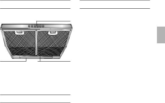
Gerätebeschreibung |
|||
|
|
.vandenborreSchalter |
|
|
|
www |
Licht/Lüfter |
|
from |
|
|
Downloaded |
|
|
|
|
|
Filtergitter |
|
Beleuchtung |
|
||
Betriebsarten
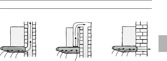
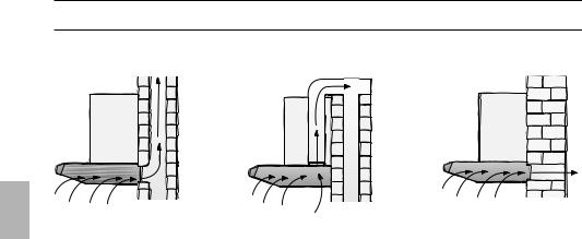
Abluftbetrieb:
Der Lüfter der Dunstabzugshaube saugt den Küchendunst an und
leitet ihn durch den Fettfilter ins Freie.
Der Fettfilter nimmt die fettigen Bestandteile des Küchendunstes auf.
Die Küche bleibt weitgehend frei von Fett und Geruch.
DBei Abluftbetrieb der Dunstabzugshaube und gleichzeitigem Betrieb schornsteinabhängiger Feuerungen
(wie z. B. Gas-, Öloder Kohleheizgeräte, Durchlauferhitzer, Warmwasserbereiter) muss für ausreichend Zuluft gesorgt werden, die von der Feuerstätte zur Verbrennung benötigt wird.
Ein gefahrloser Betrieb ist möglich, wenn der Unterdruck im Aufstellraum der Feuerstätte von 4 Pa (0,04 mbar) nicht überschritten wird.
Betriebsarten
Dies kann erreicht werden, wenn durch nicht verschließbare Öffnungen, z. B. in Türen, Fenstern und in Verbindung mit Zuluft-/Abluftmauerkasten oder durch andere techn. Maßnahmen, wie gegenseitige Verriegelung o. ä., die Verbrennungsluft nachströmen kann.
Bei nicht ausreichender Zuluft besteht Vergiftungsgefahr durch zurückgesaugte Verbrennungsgase.
Ein Zuluft-/Abluftmauerkasten allein stellt die Einhaltung des Grenzwertes nicht sicher.
Anmerkung: Bei der Beurteilung muss immer der gesamte Lüftungsverbund der Wohnung beachtet werden. Bei Betrieb von Kochgeräten, z. B. Kochmulde und Gasherd wird diese Regel nicht angewendet.
Wenn die Dunstabzugshaube im Umluftbetrieb – mit Aktivkohlefilter – verwendet wird, ist der Betrieb ohne Einschränkung möglich.
Umluftbetrieb:
Hierzu muss ein Aktivkohlefilter eingebaut werden (siehe Filter und Wartung). Der Aktivkohlefilter kann als Sonderzubehör BEIM FACHHANDEL erworben werden.
Die entsprechenden Zubehör-Nummern finden Sie am Ende dieser Gebrauchsanweisung.
Der Lüfter der Dunstabzugshaube saugt den Küchendunst an und leitet ihn durch den Fettund Aktivkohlefilter gereinigt in die Küche zurück.
Der Fettfilter nimmt die fettigen Bestandteile des Küchendunstes auf.
Der Aktivkohlefilter bindet die Geruchsstoffe.
Wird kein Aktivkohlefilter eingebaut, können keine Geruchsstoffe des Küchendunstes gebunden werden.
Falls die Dunstabzugshaube von Abluftbetrieb auf Umluftbetrieb umgestellt wird, muss die Abluftöffnung verschlossen werden um eine Gefährdung zu
vermeiden.
3

|
|
.be |
|
|
|
|
|
|
|
.vandenborre |
|
|
Vor dem ersten Benutzen |
|
|
|
Wichtige Hinweise: |
|
|
|
Diese Gebrauchsanweisung gilt für |
Bevor Sie das neue Gerät benutzen, |
|
|
|
www |
lesen Sie bitte sorgfältig die |
|
mehrere Geräte-Ausführungen. |
||
|
Es ist möglich, dass einzelne |
Gebrauchsanweisung. |
|
|
Ausstattungsmerkmale beschrieben |
Sie enthält wichtige Informationen für Ihre |
|
|
from |
|
Sicherheit sowie zum Gebrauch und zur |
|
sind, die nicht auf Ihr Gerät zutreffen. |
||
|
Diese Dunstabzugshaube entspricht den |
Pflege des Gerätes. |
|
|
Bewahren Sie die Gebrauchsund |
||
DownloadedBenutzer entstehen. |
|||
|
einschlägigen Sicherheitsbestimmungen. |
||
Reparaturen dürfen nur von Fachkräften |
Montageanweisung ggf. für einen |
|
Nachbesitzer gut auf. |
||
durchgeführt werden. |
||
|
||
Durch unsachgemäße Reparaturen |
|
|
können erhebliche Gefahren für den |
|
Ist das Gerät beschädigt, dürfen Sie es nicht in Betrieb nehmen.
Anschluss und Inbetriebnahme dürfen nur von einem Fachmann durchgeführt werden.
Wenn die Anschlussleitung dieses Gerätes beschädigt wird, muss sie durch den Hersteller oder seinen Kundendienst oder eine ähnlich qualifizierte Person ersetzt werden, um Gefährdung zu
vermeiden.
Verpackungsmaterial ordnungsgemäß entsorgen (siehe Montageanweisung).
Dunstabzugshaube nur mit eingesetzten Lampen betreiben.
Defekte Lampen sollten sofort ersetzt werden, um Überlastung der restlichen Lampen zu vermeiden.
Dunstabzugshaube nie ohne Fettfilter betreiben.
Überhitzte Fette oder Öle können sich leicht entzünden.
Darum Speisen mit Fetten oder Ölen, z. B. Pommes frites, nur unter Aufsicht zubereiten.
Unter der Dunstabzugshaube nicht flambieren.
!Brandgefahr am Fettfilter durch aufsteigende Flammen.
Über einer Feuerstätte für feste Brennstoffe (Kohle, Holz und dgl.) ist der Betrieb der Dunstabzugshaube nur bedingt gestattet (siehe Montageanweisung).
Gas-Kochmulden / Gas-Herde
Gas-Kochstellen immer sachgemäß benutzen.
Wichtig:
Die Flammen der Gas-Kochstellen müssen immer mit Kochgeschirr abgedeckt sein.
Durch die starke Hitzeentwicklung
!der offenen Gasflammen könnte die Dunstabzugshaube beschädigt werden.
4

Der Küchendunst wird am wirkungsvollsten beseitigt durch:
.be Bedienen der Dunstabzugshaubevandenborre .
Einschalten der Dunstabzugshaube
bei Kochbeginn. |
|
|
|
Ausschaltenwwwder Dunstabzugshaube |
|||
|
from |
|
|
erst einige Minuten nach Kochende. |
|
||
Downloaded |
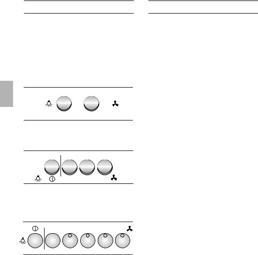
Lüfterstufen |
||
Beleuchtung |
|||
Aus |
0 |
1 |
Schwach |
Ein |
|
0 |
Aus |
|
2 |
Stark |
|
Beleuchtung Lüfterstufen
Aus 0 0
Ein |
1 |
2 |
3 |
|
Beleuchtung |
Lüfterstufen |
|
||
Ein / Aus |
|
|
Intensivstufe |
|
0 |
1 |
2 |
3 |
4 |
Filter und Wartung
Fettfilter:
Zur Aufnahme der fettigen Bestandteile des Küchendunstes sind MetallFettfilter eingesetzt.
Die Filtermatten bestehen aus unbrennbarem Metall.
Achtung:
Bei zunehmender Sättigung mit fetthaltigen Rückständen erhöht sich die Entflammbarkeit und die Funktion der Dunstabzugshaube kann beeinträchtigt werden.
Wichtig:
Durch rechtzeitiges Reinigen der MetallFettfilter wird der Brandgefahr vorgebeugt, die durch Hitzestau beim Frittieren oder Braten entstehen kann.
Reinigen der Metall-Fettfilter:
Bei normalem Betrieb (täglich 1 bis 2 Stunden) müssen die Metall-Fettfilter nach 8 bis 10 Wochen gereinigt werden.
Das Reinigen kann in der Geschirrspülmaschine erfolgen. Dabei ist eine leichte Verfärbung möglich.
Der Filter muss locker in der Geschirrspülmaschine liegen.
Er darf nicht eingeklemmt sein.
Wichtig:
Stark gesättigte Metall-Fettfilter nicht zusammen mit Geschirr reinigen.
Beim Reinigen von Hand, die Fettfilter in heißer Spüllauge einweichen.
Danach abbürsten, gut ausspülen und abtropfen lassen.
5
.be Filter und Wartungvandenborre
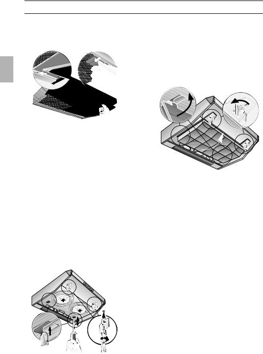
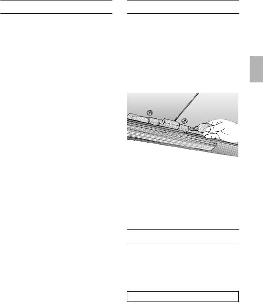
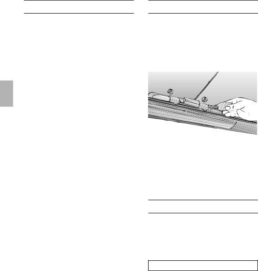
Ausund Einbauen der Metall-Fettfilter:
1. Drücken Sie die Raste an den Fettfiltern . in Pfeilrichtungwwwein und klappen Sie die
Fettfilter ab. Downloaded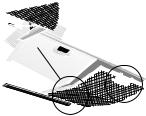


2.Reinigen Sie die Fettfilter.
3.Setzen Sie die gereinigten Fettfilter wieder ein.
Aktivkohlefilter:
Zum Binden der Geruchsstoffe beim Umluftbetrieb.
Bauen Sie die Fettfilter aus (siehe Ausund Einbauen der Metall-Fettfilter).
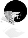
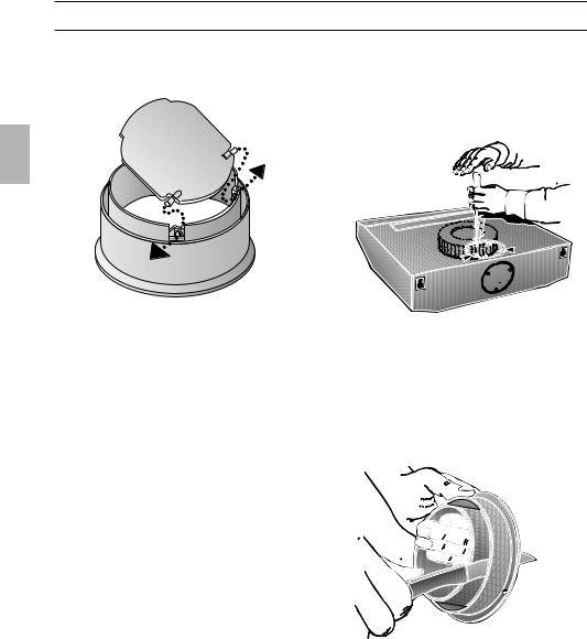
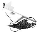
1.Stecken Sie die Schrauben durch die Flügelmuttern und die Hülsen und drehen Sie die Schrauben links und rechts in den Zwischenboden ein (nur beim ersten Einbau erforderlich).
– Schrauben, Flügelmuttern und Hülsen liegen dem Aktivkohlefilter bei –.
2.Drücken Sie mit einem Schraubendreher oder ähnlichem die beiden Laschen am Gehäuse nach innen ein (nur beim ersten Einbau erforderlich).
3.Setzen Sie den Aktivkohlefilter hinten ein, klappen ihn hoch und verriegeln ihn links
und rechts mit den Flügelmuttern.
Die Laschen links uns rechts am Aktivkohlefilter sind für die 50 cm breite Dunstabzugshaube eingeklappt.
Sie müssen für die 60 cm und 90 cm breite Dunstabzugshaube hochgeklappt werden.
Wechsel des Aktivkohlefilters:
Bei normalem Betrieb (täglich 1 bis 2 Stunden) muss der Aktivkohlefilter ungefähr 1 x im Jahr ausgetauscht werden.
Der Aktivkohlefilter ist im FACHHANDEL erhältlich. (Siehe Sonderzubehör).
Nur Originalfilter verwenden.
Dadurch wird eine optimale Funktion gewährleistet.
Entsorgung des alten Aktivkohlefilters:
Aktivkohlefilter enthalten keine Schadstoffe. Sie können z. B. als Restmüll entsorgt werden.
6
.be Reinigen und Pflegenvandenborre
Dunstabzugshaube durch Ziehen des Netzsteckers bzw. Ausschalten der Sicherung stromlos.machen.
Beim Reinigenwwwder Fettfilter die zugänglichen Gehäuseteile von abgelagertemfrom Fett reinigen.
Dadurch wird der Brandgefahr
vorgebeugt und die optimale Funktion Downloadedbleibt erhalten.
Zum Reinigen der Dunstabzugshaube heiße Spüllauge oder mildes Fensterputzmittel verwenden.
Kratzen Sie angetrocknete Verschmutzung nicht ab, sondern weichen Sie diese mit einem feuchten Tuch auf.
Keine scheuernden Mittel oder kratzende Schwämme verwenden.
Hinweis: Alkohol (Spiritus) nicht auf Kunststoffflächen anwenden, es könnten matte Stellen entstehen.
Vorsicht! Küche ausreichend belüften, keine offene Flamme.
Die Bedientasten nur mit milder Spüllauge und einem weichen, feuchten Tuch reinigen.
Keinen Edelstahlreiniger für die Bedientasten verwenden.
Edelstahloberflächen:
Verwenden Sie einen milden nicht scheuernden Edelstahlreiniger.
Reinigen Sie nur in Schliffrichtung.
Edelstahloberflächen nicht mit kratzenden Schwämmen und nicht mit sand-, soda-, säureoder chloridhaltigen Putzmitteln reinigen!
Aluminium-, Lackund Kunststoffoberflächen:
Verwenden Sie ein weiches, fusselfreies Fensteroder Microfasertuch.
Keine trockenen Tücher verwenden.
Verwenden Sie ein mildes Fensterreinigungsmittel.
Keine aggressiven, säureoder laugenhaltigen Reiniger verwenden.
Keine Scheuermittel verwenden.
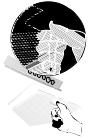
Auswechseln der Lampen
1.Schalten Sie die Dunstabzugshaube aus und machen Sie durch Ziehen des Netzsteckers oder Ausschalten der Sicherung die Dunstabzugshaube stromlos.
2.Bauen Sie die Fettfilter aus (siehe Filter und Wartung).
3.Tauschen Sie die Lampe aus (handelsübliche Glühlampen max. 40 Watt, Sockel E 14).
4.Bauen Sie die Fettfilter wieder ein.
5.Stellen Sie durch Einstecken des Netzsteckers oder durch Einschalten der Sicherung die Stromversorgung wieder her.
Störungen
Bei eventuellen Rückfragen oder Störungen, Kundendienst anrufen.
(Siehe Kundendienststellenverzeichnis).
Bei Anruf bitte angeben:
E-Nr. FD
Tragen Sie die Nummern in obige Felder ein. Die Nummern sind auf dem Typenschild, nach Abnahme der Fettfilter, im Innenraum der Dunstabzugshaube zu finden.
7
|
|
|
|
.be |
Über Gas-Kochstellen ist die Montage |
|
|
Altgeräte sind kein.vandenborrewertloser Abfall. |
|||
|
Montageanweisung: |
|
|||
|
|
Wichtige Hinweise |
|
|
|
|
|
|
www |
|
der Dunstabzugshaube bei einem |
|
|
Durch umweltgerechte Entsorgung können |
|||
|
|
wertvolle Rohstoffe wiedergewonnen |
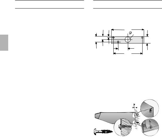
Mindestabstand von 650 mm – Abb. 1 – |
||
|
|
werden. |
|
|
nur zulässig, wenn folgende Nennwärme- |
|
|
|
|||
|
|
Bevor Sie das Altgerät entsorgen, machen |
belastungen (Hs) nicht überschritten |
||
|
|
Sie es unbrauchbar.from |
|
werden: |
|
|
Downloaded |
|
|
Gas-Herde |
|
|
|
Ihr neues Gerät wurde auf dem Weg zu |
Belastung einer Kochstelle max. 03,0 kW |
||
|
|
Ihnen durch die Verpackung geschützt. Alle |
Belastung aller Kochstellen max. 08,3 kW |
||
|
|
eingesetzten Materialien sind umweltver- |
Belastung des Backofens max. 03,9 kW |
||
|
|
träglich und wieder verwertbar. Bitte helfen |
|||
|
|
Gas-Kochmulden |
|||
|
|
Sie mit und entsorgen Sie die Verpackung |
|||
|
|
Belastung einer Kochstelle max. 03,9 kW |
|||
|
|
umweltgerecht. |
|
||
|
|
Über aktuelle Entsorgungswege informieren |
Belastung aller Kochstellen max. 11,3 kW |
||
|
|
Gas-Glaskeramikkochfeld |
|||
|
|
Sie sich bitte bei Ihrem Fachhändler oder |
|||
|
|
bei Ihrer Gemeindeverwaltung. |
Die Angaben über Nennwärme- |
||
|
|
Die Dunstabzugshaube ist für Abluft- |
belastung gelten nicht für geschlossene |
||
|
|
Gas-Glaskeramikkochfelder. |
|||
|
|
und Umluftbetrieb verwendbar. |
Unbedingt die Angaben des Kochfeld- |
||
|
|
Die Dunstabzugshaube immer über der |
Herstellers beachten. |
||
|
|
Herde für feste Brennstoffe |
|||
|
|
Mitte der Kochstellen anbringen. |
Es gelten sinngemäß die maximalen |
||
|
|
Mindestabstand zwischen Elektro- |
|||
|
|
Nennwärmebelastungen und der |
|||
|
|
kochstellen und Unterkante der Dunstab- |
Mindestabstand wie bei Gas-Herden. |
||
|
|
zugshaube: |
|
650 mm, Abb. 1. |
Über einer Feuerstätte für feste |
|
|
|
|
|
|
|
|
Zusätzliche Hinweise bei Gas-Koch- |
Brennstoffe, von der eine Brandgefahr |
||
|
|
(z. B. Funkenflug) ausgehen kann, ist die |
|||
|
|
geräten: |
|
|
Montage der Dunstabzugshaube nur dann |
|
|
Bei der Montage von Gaskochstellen |
zulässig, wenn die Feuerstätte eine |
||
|
|
geschlossene nicht abnehmbare |
|||
|
|
sind die national einschlägigen gesetzlichen |
|||
|
|
Abdeckung hat und die länderspezifischen |
|||
|
|
Bestimmungen (z. B. in Deutschland: |
|||
|
|
Vorschriften eingehalten werden. |
|||
|
|
Technische Regeln Gasinstallation TRGI) zu |
|||
|
|
Diese Einschränkung gilt nicht für Gas- |
|||
|
|
beachten. |
|
|
|
|
|
|
|
Herde und Gas-Mulden. |
|
|
|
Es müssen die jeweils gültigen Einbau- |
|||
|
|
Je kleiner der Abstand zwischen |
|||
|
|
vorschriften und die Einbauhinweise der |
|||
|
|
Gas-Gerätehersteller beachtet werden. |
Dunstabzugshaube und Kochstellen desto |
||
|
|
größer ist die Möglichkeit, dass sich durch |
|||
|
|
Die Dunstabzugshaube darf nur an |
|||
|
|
aufsteigenden Wasserdampf unten an der |
|||
|
|
einer Seite neben einem Hochschrank oder |
Dunstabzugshaube Tropfen bilden können. |
||
|
|
einer hohen Wand eingebaut werden. |
|
||
|
|
Abstand mind. 50 mm. |
|
|
|
8
|
.be |
|
|
|
.vandenborre |
|
|
Vor der Montage |
|
||
Abluftbetrieb |
|
||
from |
www |
|
|
|
|
||
DownloadedDie Abluft wird über einen Lüftungsschacht |
Bei nicht ausreichender Zuluft besteht |
||
nach oben, oder direkt durch die Außen- |
Vergiftungsgefahr durch zurückgesaugte |
||
wand ins Freie geleitet. |
Verbrennungsgase. |
||
DDie Abluft darf weder in einen in Betrieb |
Ein Zuluft-/Abluftmauerkasten allein stellt |
||
befindlichen Rauchoder Abgaskamin noch |
die Einhaltung des Grenzwertes nicht |
||
in einen Schacht, welcher der Entlüftung |
sicher. |
||
von Aufstellungsräumen von Feuerstätten |
Anmerkung: Bei der Beurteilung muss |
||
dient, abgegeben werden. |
|||
immer der gesamte Lüftungsverbund der |
|||
|
|
||
Bei der Ableitung von Abluft sind die |
Wohnung beachtet werden. Bei Betrieb von |
||
behördlichen und gesetzlichen |
Kochgeräten, z. B. Kochmulde und Gas- |
||
Vorschriften (z. B. Landesbauordnungen) |
herd wird diese Regel nicht |
||
zu beachten. |
|
angewendet. |
|
Bei Abführung der Luft in nicht in Betrieb |
Wenn die Dunstabzugshaube im Umluftbe- |
||
befindliche Rauchoder Abgaskamine ist |
trieb – mit Aktivkohlefilter – verwendet wird, |
||
die Zustimmung des zuständigen |
ist der Betrieb ohne Einschränkung |
||
Schornsteinfegermeisters einzuholen. |
möglich. |
||
DBei Abluftbetrieb der Dunstabzugs- |
Bei Abluftbetrieb sollte in der Dunstab- |
||
haube und gleichzeitigem Betrieb |
zugshaube eine Rückstauklappe eingebaut |
||
schornsteinabhängiger Feuerungen (wie |
werden, wenn sie nicht im Abluftrohr oder |
||
z. B. Gas-, Öloder Kohleheizgeräte, |
Mauerkasten vorhanden ist. |
||
Durchlauferhitzer, Warmwasserbereiter) |
Ist dem Gerät keine Rückstauklappe |
||
muss für ausreichend Zuluft gesorgt |
beigelegt, kann sie über den Fachhandel |
||
werden, die von der Feuerstätte zur |
bezogen werden (siehe Sonderzubehör in |
||
Verbrennung benötigt wird. |
der Gebrauchsanweisung). |
||
Ein gefahrloser Betrieb ist möglich, wenn |
Den inneren Teil des Abluftstutzens |
|
der Unterdruck im Aufstellraum der |
||
nicht herausschneiden. |
||
Feuerstätte von 4 Pa (0,04 mbar) nicht |
||
Montieren der Rückstauklappe: |
||
überschritten wird. |
||
Die beiden Zapfen der Rückstauklappe |
||
Dies kann erreicht werden, wenn durch |
||
in die Löcher am Abluftstutzen |
||
nicht verschließbare Öffnungen, z. B. in |
||
einrasten. |
||
Türen, Fenstern und in Verbindung mit |
||
|
||
Zuluft-/Abluftmauerkasten oder durch |
|
|
andere techn. Maßnahmen, wie |
|
|
gegenseitige Verriegelung o. ä., die |
|
|
Verbrennungsluft nachströmen kann. |
|
9
Wird die Abluft durch die Außenwand geleitet, sollte ein Teleskop-Mauerkasten
.be Vor der Montagevandenborre
verwendet werden. .
|
from |
www |
Downloaded |
|
|
|
|
Abluft nach oben:
Rohrdurchmesser: 100 oder 120 mm
Deckel an der Oberseite der Dunstabzugshaube ausbrechen. Dazu mit einem Werkzeug an den Haltepunkten kurz aufschlagen.
Optimale Leistung der Dunstabzugshaube:
Kurzes, glattes Abluftrohr.
Möglichst wenig Rohrbögen.
Möglichst große Rohrdurchmesser (am besten l 120 mm) und große Rohrbögen.
Der Einsatz von langen, rauhen Abluftrohren, vielen Rohrbögen oder kleineren Rohrdurchmessern führt zu einer Abweichung von der optimalen Luftleistung und gleichzeitig zu einer Geräuscherhöhung.
Rundrohre Kurzes Abluftrohr:
Innendurchmesser mind. 100 mm, längeres Abluftrohr:
Innendurchmesser mind. 120 mm.
Flachkanäle müssen einen gleichwertigen Innenquerschnitt wie Rundrohre haben.
Sie sollten keine scharfen Umlenkungen haben.
l 100 mm ca. 078 cm2 l 125 mm ca. 113 cm2
Bei abweichenden Rohrdurchmessern: Dichtstreifen einsetzen.
Bei Abluftbetrieb für ausreichend Zuluft sorgen.
Das Werkzeug senkrecht halten, um eine Beschädigung des Lüfters zu vermeiden.
Das ausgebrochene Blechteil herausnehmen (es könnte Geräusche und Störungen verursachen).
Bei Rohrdurchmesser 120 mm, den inneren Teil des Abluftstutzens herausschneiden.
Abluftstutzen einsetzen und bis Anschlag verdrehen.
10
|
|
.be |
|
|
|
.vandenborre |
|
Vor der Montage |
|
||
Abluft nach hinten: |
Das Außenteil des Abluftstutzens |
||
Rohrdurchmesser: 100 mm |
abschneiden. |
||
|
|
www |
|
Deckel an der Rückwand der Dunst- |
|
||
|
abzugshaube ausbrechen. Dazu mit |
|
|
|
einem Werkzeug an den Haltepunkten |
|
|
|
from |
|
|
|
kurz aufschlagen. |
|
|
Das Innenteil einsetzen und bis Anschlag verdrehen.
Umluftbetrieb
Das Werkzeug senkrecht halten, um eine Beschädigung des Lüfters zu vermeiden.
Das ausgebrochene Blechteil herausnehmen (es könnte Geräusche und
Störungen verursachen).
2-motorige-Ausführung:
Am Kunststoffteil die Öffnung nach hinten herstellen. Dazu die 3 Rippen durchtrennen und das abgeschnittene Teil herausnehmen.
Mit Aktivkohlefilter, wenn keine Möglichkeit für Abluftbetrieb vorhanden ist.
Die durch einen zusätzlichen Aktivkohlefilter gereinigte Luft wird wieder in den Raum zurückgeführt.
Einsetzen des Aktivkohlefilters siehe Gebrauchsanweisung.
Falls die Dunstabzugshaube von Abluftbetrieb auf Umluftbetrieb umgestellt wird, muss die Abluftöffnung verschlossen werden um eine Gefährdung zu vermeiden.
11
.be
Elektrischer Anschluss
vorschriftsmäßig installiertevandenborreSchutzkontaktsteckdose angeschlossen. werden. Die Schutzkontaktsteckdose möglichst
Die Dunstabzugshaube darf nur an eine
zugänglich in der Nähe der Dunstabzugs- |
|
|
www |
haube anbringen. |
|
from |
|
Die Schutzkontaktsteckdose sollte über
einen eigenen Stromkreis angeschlos-
Downloadedsen werden.
Elektrische Daten:
Sie sind auf dem Typenschild nach Abnahme der Filterrahmen – im Innenraum des Gerätes – zu finden.
Bei Reparaturen das Gerät generell stromlos machen.
Länge der Anschlussleitung: 1,30 m. Bei erforderlichem Festanschluss:
Die Dunstabzugshaube darf nur durch einen beim zuständigen ElektrizitätsVersorgungsunternehmen eingetragenen Elektro-Installateur angeschlossen werden.
Installationsseitig ist eine Trennvorrichtung vorzusehen. Als Trennvorrichtung gelten Schalter mit einer Kontaktöffnung von mehr als 3 mm und allpoliger Abschaltung.
Dazu gehören LS-Schalter und Schütze.
Diese Dunstabzugshaube entspricht den EG-Funkentstörbestimmungen.
Befestigung
Befestigung an der Wand
60 cm breite Dunstabzugshaube: Mit 3 Schrauben.
|
21 |
598 |
|
100 |
|
102 |
57 |
127 |
|
||
|
|
180 |
|
|
536 |
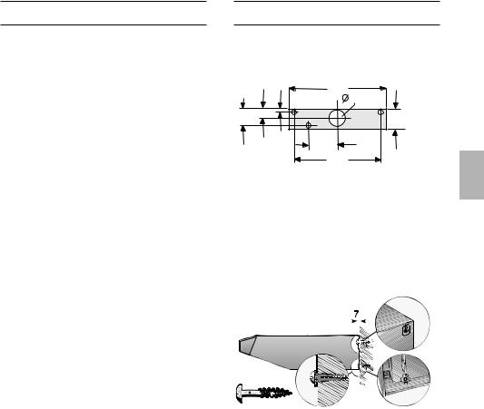
1.Befestigungsbohrungen anreißen. Maße aus den Bildern entnehmen oder Schablone verwenden.
2.Löcher l 8 mm bohren und Dübel wandbündig eindrücken.
3.Die oberen Schrauben (links und rechts) bis zu einem Abstand von ca. 7 mm, vom Schraubenkopf zur Wand, einschrauben.
4.Filtergitter abnehmen
(siehe Gebrauchsanweisung).
5.Dunstabzugshaube einhängen.
6.Die untere Schraube mit Unterlegscheibe vom Innenraum der Dunstabzugshaube aus festschrauben.
12
|
|
|
|
.be |
Befestigung |
.vandenborre |
|||
|
|
|||
Befestigung am Oberschrank |
|
|||
60 cm breite Dunstabzugshaube: |
|
|||
|
|
www |
|
|
Mit 4 Schrauben. |
|
|
||
Downloaded |
from |
|
|
|
|
|
|
163 |
|
|
|
|
|
|
|
|
|
0 |
|
|
|
|
3 |
|
598
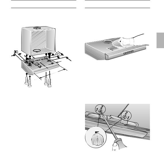
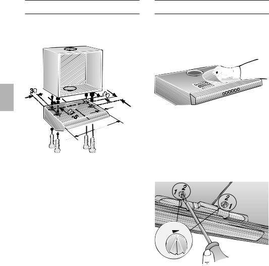
1.Maße für die Befestigungslöcher aus den Bildern entnehmen oder Schablone an den Boden des Oberschrankes anlegen.
2.Befestigungslöcher anreißen und mit Stichel vorstechen.
Bei Abluftbetrieb nach oben, die Abluftöffnung anreißen und aussägen.
Lage der Anschlussleitung berücksichtigen, ggf. den Schrank aussägen.
3.Filtergitter abnehmen
(siehe Gebrauchsanweisung).
4.Dunstabzugshaube an den Schrankboden festschrauben.
Gewicht in kg:
|
|
|
|
|
|
|
|
|
|
Breite |
|
|
Abluft |
|
|
Umluft |
|
|
|
|
|
|
|
|
|
|
|
|
|
|
|
|
|
|
|
|
60 cm |
|
|
10,0 |
|
|
11,0 |
|
|
2-motorig |
|
|
|
|
|
||
|
|
|
|
|
|
|
|
|
|
|
|
|
|
|
|
|
|
Konstruktionsänderungen im Rahmen der technischen Entwicklung bleiben vorenthalten.
Fertigmontage
Abluftbetrieb:
Beiliegende Abdeckfolie über das Luftaustrittsgitter an der Oberseite der Dunstabzugshaube aufkleben.
Dabei auf saubere Oberfläche achten.
Rohrverbindung herstellen.
Bei 2-motoriger Dunstabzugshaube
Einstellen der Betriebsart:
Abluftbetrieb: Stellung 1
Umluftbetrieb: Stellung 2
Einstellung jeweils links und rechts mit einem Schraubendreher.
2
1
Elektrische Verbindung herstellen.
Filtergitter einsetzen
(siehe Gebrauchsanweisung).
13

Operating instructions: |
.be |
|||
|
||||
Description of appliance |
|
|||
|
|
.vandenborreSwitch/light/ |
||
|
|
www |
fan |
|
|
from |
|
|
|
Downloaded |
|
|
|
|
|
|
|
Filter grille |
|
Light |
|
|
|
|
Operating modes
Exhaust-air mode:
The extractor-hood fan extracts the kitchen vapours and conveys them through the grease filter into the atmosphere.
The grease filter absorbs the solid particles in the kitchen vapours.
The kitchen is kept almost free of grease and odours.
DIf the extractor hood is operated in exhaust-air mode at the same time as a flue-type heater (e.g. gas, oil or solid-fuel heater, instantaneous water heater, boiler), ensure that there is an adequate air supply which the heater requires for combustion.
Safe operation is possible provided that the partial vacuum in the room in which the heater is installed does not exceed 4 Pa (0.04 mbar).
This can be achieved if the combustion air is able to flow through non-lockable openings, e.g. in doors, windows and in conjunction with an air supply/air-intake wall box or by other technical procedures such as reciprocal interlocking.
Operating modes
If the air intake is inadequate, there is a risk of poisoning from combustion gases which are drawn back into the room.
An air-intake/exhaust-air wall box by itself is no guarantee that the limiting value will not be exceeded.
Note: When assessing the overall requirement, the combined ventilation system for the entire household must be taken into consideration. This rule does not apply to the use of cooking appliances, such as hobs and ovens.
Unrestricted operation is possible if the extractor hood is used in recirculating mode
– with activated carbon filter.
Circulating-air mode:
An activated carbon filter must be
fitted for this operating mode (see Filters and maintenance). The activated carbon filter can be purchased as an optional accessory FROM YOUR DEALER.
The corresponding accessory numbers can be found at the end of these operating instructions.
The extractor-hood fan extracts the kitchen vapours which are purified in the grease filter and activated carbon filter and then conveyed back into the kitchen.
The grease filter absorbs the grease particles in the kitchen vapours.
The activated carbon filter binds the odorous substances.
If no activated carbon filter is installed, it is not possible to bind the odorous substances in the cooking vapours.
If the extractor hood is switched from exhaust-air mode to circulating-air mode, the exhaust-air opening must be sealed to prevent a hazardous situation (see optional accessories in the Instructions for use).
14

|
|
|
|
.be |
|
|
|
|
|
||
|
Before using for the first time |
|
|||
|
|
|
|
|
|
|
Important notes: |
|
|||
|
The Instructions for Use apply to several |
Before using your appliance for the first |
|||
|
|
|
|
.vandenborre |
time, please read these Instructions for |
|
|
versions of this appliance. Accordingly, |
|||
|
|
you may find descriptions of individual |
Use carefully. They contain important |
||
|
|
features that do not apply to your |
information concerning your personal |
||
|
|
|
|
www |
safety as well as on use and care of the |
|
|
specific appliance. |
|||
|
This extractor hood complies with all |
appliance. |
|||
|
|
||||
|
|
|
from |
|
Please retain the operating and |
|
|
relevant safety regulations. |
|||
Downloaded |
|
|
installation instructions for a subsequent |
||
|
|
Repairs should be carried out by |
|
||
qualified technicians only. |
owner. |
|
|
Improper repairs may put the user at |
|
considerable risk. |
|
Do not use the appliance if damaged.
The appliance is not intended for use by young children or infirmed persons without supervision.
Young children should be supervised to ensure they do not play with the appliance.
If the connecting cable for this appliance is damaged, the cable must be replaced by the manufacturer or his customer service or a similarly qualified person in order to prevent serious injury to the user.
The appliance may be connected to the mains by a qualified technician only.
Dispose of packaging materials properly (see Installation instructions).
Light bulbs must always be fitted when the extractor hood is in use.
Defective bulbs should be replaced immediately to prevent the remaining bulbs from overloading.
Never operate the extractor hood without a grease filter.
Overheated fat or oil can easily catch
fire.
If you are cooking with fat or oil, e.g. chips, etc., never leave the cooker unattended.
Do not flambé food directly under the extractor hood.
!Risk of grease filter catching fire due to flames.
Restrictions apply to the use of the extractor hood over a solid-fuel burner (coal, wood, etc.). (See Installation instructions).
Gas hobs / gas cookers
Always use gas hobs in a proper and safe manner.
Important:
The flames from the gas hob must always be covered by pots or pans.
The intense heat generated by the gas
!flames could cause damage to the extractor hood.
15
.be Operating the extractorvandenborrehood .
Cooking vapours are best eliminated by:
Switching on the extractor hood when
you start cooking.www
Only switching off the extractor hood a fewfromminutes after you have finished cooking.
Downloaded |
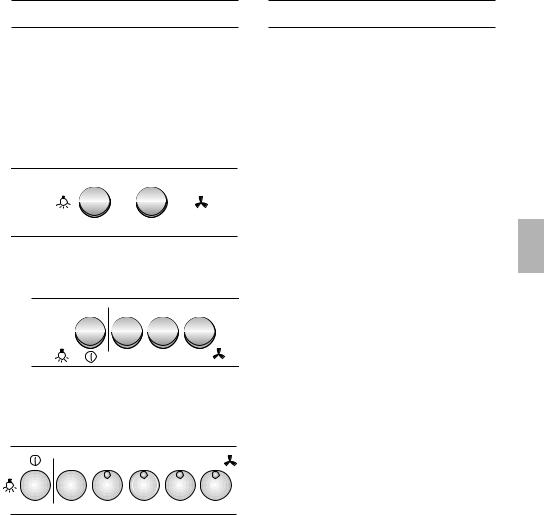
Fan settings |
|
|
|
Light |
|
|
Off |
0 |
1 |
Low |
On |
|
0 |
Off |
|
2 |
High |
|
Light |
|
Fan settings |
|
||
OFF |
0 |
0 |
|
|
|
ON |
|
1 |
2 |
3 |
|
Light |
|
Fan settings |
|
|
|
ON / OFF |
|
|
|
Intensive setting |
|
|
0 |
1 |
2 |
3 |
4 |
Filters and maintenance
Grease filters:
Metal filters are used to trap the greasy element of the vapours that develop during cooking.
The filter mats are made from noncombustible metal.
Caution:
As the filter becomes more and more saturated with grease, not only does the risk of it catching fire increase but the efficiency of the extractor hood can also be adversely affected.
Important:
By cleaning the metal grease filters at appropriate intervals, the possibility of them catching fire as a result of a build-up of heat such as occurs when deep-fat frying or roasting is taking place, is reduced.
Cleaning the metal grease filters:
In normal operation (1 to 2 hours daily), the metal grease filter must be cleaned after 8 to 10 weeks.
The filters can be cleaned in a dishwasher. It is however possible that they will become slightly discoloured.
The filter must be placed loosely, and NOT wedged, in the dishwasher.
Important:
Metal filters that are saturated with grease should not be washed together with other dishes etc.
When cleaning the filters by hand, soak them in hot soapy water first of all. Then brush the filters clean, rinse them
thoroughly and leave the water to drain off.
16

.be Filters and maintenancevandenborre
Removing and inserting the metal grease filters:
1. Press the catch on.the grease filters inwards andwwwfold the filters down.
Downloaded


2.Clean the filters.
3.Insert the clean filters back into the hood.
Activated carbon filter:
For binding the odorous substances in circulating-air mode.
Remove the metal filters (see "Removing and inserting the metal grease filters").
1.Insert the screws through the wing nuts and sleeves and screw the screws into the left and right sides of the intermediate base (required only during the initial installation). Screws, wing nuts and sleeves are enclosed with the
activated carbon filter –.
2.Using a screwdriver or similar tool, press the two lugs on the housing inwards (required only during the initial installation).
3.Insert the activated carbon filter at the rear, fold up and lock into position on the
left and right with the wing nuts.
The lugs on the left and right sides of the activated carbon filter are folded in for the 50 cm wide extractor hood. They must be folded up for the 60 cm and 90 cm wide extractor hoods.
Replacing the activated carbon filter:
During normal operation (daily 1 to 2 hours) the activated carbon filter must be replaced approximately 1 x year.
The activated carbon filter can be purchased FROM YOUR DEALER (see Optional accessories).
Use only original filters.
These ensure optimum function.
Disposal of the old activated carbon filter:
Activated carbon filters do not contain any harmful substances. They can be disposed of as residual waste.
17
.be Cleaning and carevandenborre .
Isolate the extractor hood by pulling out the mains plug or switching off the fuse.
|
|
www |
When cleaning the grease filters, remove |
||
|
grease deposits from accessible parts of |
|
|
the housing. This prevents the risk of fire |
|
|
and ensures that the extractor hood |
|
|
continues operating at maximum |
|
|
efficiency.from |
|
DownloadedDo not use scouring agents or abrasive |
||
|
Clean the extractor hood with a hot soap |
|
solution or a mild window cleaner.
Do not scrape off dried-on dirt but wipe off with a damp cloth.
sponges.
Note: Do not use alcohol (spirit) on plastic surfaces, as dull marks may appear.
Caution: Ensure that the kitchen is adequately ventilated. Avoid naked flames!
Clean the operating buttons with a mild soapy solution and a soft, damp cloth only. Do not use stainless-steel cleaner to clean the operating buttons.
Stainless steel surfaces:
Use a mild non-abrasive stainless steel cleaner.
Clean the surface in the same direction as it has been ground and polished.
Do not use any of the following to clean stainless steel surfaces: abrasive sponges, cleaning agents containing sand, soda, acid or chloride!
Aluminium and plastic surfaces:
Use a soft, non-linting window cloth or micro-fibre cloth.
Do not use dry cloths.
Use a mild window cleaning agent.
Do not use aggressive, acidic or caustic cleaners.
Do not use abrasive agents.
Replacing the light bulbs
1.Switch off the extractor hood and isolate the extractor hood by pulling out the mains plug or switching off the fuse.
2.Remove the grease filter
(see Filters and maintenance).
3.Replace the bulb (standard filament bulb, max 40 W, E14 bulb holder).
4.Re-insert the grease filters.
5.Reconnect the power by inserting the mains plug or by switching on the fuse.
Malfunctions
Please contact customer service regarding any queries or malfunctions.
(See customer-service directory).
When calling, please quote:
E-No. FD
Enter the numbers in the above box. The numbers can be found on the rating plate – remove the grease filter inside the extractor hood to reveal the rating plate.
18
|
|
|
.be |
The installation of the extractor hood |
|
||
|
Old appliances are.vandenborrenot worthless |
|
|||||
|
Installation Instructions: |
|
|
|
|
||
|
Important information |
|
|
|
|
||
|
|
|
www |
above gas cooking devices, at a |
|
||
|
rubbish. Valuable raw materials can be |
|
|||||
|
reclaimed by recycling old appliances. |
minimum height of 650 mm – Fig. 1 – is |
|
||||
|
|
from |
|
Gas cookers |
|
|
|
|
Before disposing of your old appliance, |
permitted provided that the following |
|
||||
|
render it unusable. |
nominal heat loads (Hs) are not exceeded: |
|
||||
Downloaded |
|
|
|
|
|
|
|
|
You received your new appliance in a |
Load of one hotplate |
max. 03.0 kW |
|
|||
|
protective shipping carton. All packaging |
Load of all hotplates |
max. 08.3 kW |
|
|||
|
materials are environmentally friendly and |
Load of the oven |
max. 03.9 kW |
|
|||
|
recyclable. Please contribute to a better |
|
|||||
|
Gas hobs |
|
|
|
|||
|
environment by disposing of packaging |
max. 03.9 kW |
|
||||
|
materials in an environmentally-friendly |
Load of one hotplate |
|
||||
|
Load of all hotplates |
max. 11.3 kW |
|
||||
|
manner. |
|
|
||||
|
Please ask your dealer or inquire at your |
Gas ceramic hotplate |
|
|
|
||
|
local authority about current means of |
The nominal heat load specifications do |
|
||||
|
disposal. |
|
not apply to closed gas ceramic hobs. |
|
|||
|
The extractor hood can be used in |
Always observe the specifications of the |
|
||||
|
hob manufacturer. |
|
|
|
|||
|
exhaust air or circulating air mode. |
Solid-fuel cookers |
|
|
|
||
|
Always mount the extractor hood over |
The maximum nominal heat loads and |
|
||||
|
the minimum distance are the same as |
|
|||||
|
the centre of the hob. |
for gas cookers. |
|
|
|
||
|
Minimum distance between electric |
|
|
|
|||
|
The extractor hood may only be |
|
|||||
|
hob and bottom edge of extractor hood: |
installed over a fireplace which burns solid |
|
||||
|
650 mm, Fig. 1. |
|
|||||
|
fuel (fire hazard due to flying sparks) if the |
|
|||||
|
|
|
|
|
|||
|
|
|
|
fireplace has a closed, non-detachable |
|
||
|
Additional information concerning gas |
cover and national regulations have been |
|
||||
|
cookers: |
|
observed. This restriction does not apply to |
|
|||
|
When installing gas hotplates, comply |
gas cookers and gas hobs. |
|
|
|
||
|
The smaller the gap between the |
|
|||||
|
with the relevant national statutory |
|
|||||
|
regulations (e.g. in Germany: Technische |
extractor hood and hotplates, the greater |
|
||||
|
Regeln Gasinstallation TRGI). |
the likelihood that droplets will form on the |
|
||||
underside of the extractor hood. Always comply with the currently valid
regulations and installation instructions supplied by the gas appliance manufacturer.
Only one side of the extractor hood may be installed next to a high-sided unit or high wall. Gap at least 50 mm.
19
|
.be |
|
|
|
.vandenborre |
|
|
Prior to installation |
|
||
Exhaust-air mode |
|
||
from |
www |
|
|
|
|
||
DownloadedThe exhaust air is discharged upwards |
This can be achieved if the combustion air |
||
through a ventilation shaft or directly |
is able to flow through non-lockable |
||
through the outside wall into the open. |
openings, e.g. in doors, windows and in |
||
DExhaust air must not be discharged via |
conjunction with an air supply/air-intake wall |
||
box or by other technical procedures such |
|||
a smoke or exhaust gas flue which is |
|||
as reciprocal interlocking. |
|||
already in use or via a shaft which is used |
|||
|
|||
for ventilating rooms in which fireplaces are |
If the air intake is inadequate, there is a |
||
located. |
|
risk of poisoning from combustion gases |
|
Discharge exhaust air in accordance |
which are drawn back into the room. |
||
An air-intake/exhaust-air wall box by itself is |
|||
with official and statutory regulations |
|||
(e.g. national building regulations). |
no guarantee that the limiting value will not |
||
Discharge of air into smoke or exhaust air |
be exceeded. |
||
Note: When assessing the overall |
|||
flues which are not in use requires the |
|||
consent of a heating engineer. |
requirement, the combined ventilation |
||
DIf the extractor hood is operated in |
system for the entire household must be |
||
taken into consideration. This rule does not |
|||
exhaust-air mode at the same time as a |
|||
apply to the use of cooking appliances, |
|||
flue-type heater (e.g. gas, oil or solid-fuel |
|||
such as hobs and gas cookers. |
|||
heater, instantaneous water heater, boiler), |
|||
The extractor hood can be used without |
|||
ensure that there is an adequate air |
|||
supply which the heater requires for |
restriction in circulating air mode – with an |
||
combustion. |
|
activated carbon filter. |
|
Safe operation is possible provided that the partial vacuum in the room in which the heater is installed does not exceed 4 Pa (0.04 mbar).
This can be achieved if the combustion air is able to flow through non-lockable openings, e.g. in doors, windows and in conjunction with an air supply/air-intake wall box or by other technical procedures such as reciprocal interlocking.
An extractor hood which is operated in exhaust-air mode should be fitted with a one-way flap if there is no one-way flap in the exhaust-air pipe or wall box.
If a one-way flap is not supplied with the appliance, you can purchase one from your dealer (see optional accessories in the Instructions for use).
Do NOT cut out the inner part of the exhaust-air connection.
Fitting the one-way flap:
Insert the two lugs on the one-way flap into the holes in the exhaust-air connection.
20
should be used. |
.be |
|
||
.vandenborre |
|
|||
Before installation |
|
|||
If the exhaust air is conveyed through |
Exhaust air upwards: |
|||
the exterior wall, a telescopic wall box |
Pipe diameter: 100 or 120 mm |
|||
|
|
www |
Break off cover on the top of the |
|
|
|
|
|
extractor hood; strike the retaining points |
|
from |
|
|
with a tool. |
Downloaded |
|
|
|
|
|
|
|
|
|
Optimum performance of the extractor hood:
Short, smooth exhaust-air pipe.
Minimum number of pipe bends.
Largest possible pipe diameter
(120 mm dia. recommended) and large pipe bends.
If long, rough exhaust-air pipes, many pipe bends or smaller pipe diameters are used, the air extraction rate will no longer be at an optimum level and there will be an increase in noise.
Round pipes:
Short discharge pipe:
Inner diameter at least 100 mm, extended discharge pipe:
Inner diameter at least 120 mm.
Flat ducts must have an inner crosssection equivalent to round pipes with an inner diameter of 100/120 mm.
There should be no sharp bends.
100 m dia approx. 178 cm2
125 m dia approx. 113 cm2
If pipe diameters differ:
Insert sealing strip.
Ensure an adequate air supply for exhaust-air mode.
To prevent damage to the fan, hold the tool vertically.
Remove the broken off metal part (possibly a noisy and disruptive procedure).
If the pipe diameter is 120 mm, cut out the inner part of the exhaust-air connection.
Insert the exhaust-air connection and turn as far as possible.
21

.be
Before installation
Exhaust air towards the rear: |
|
Pipe diameter: 100 mm |
|
|
.vandenborre |
Break off cover on the rear panel of the |
|
|
extractor hood; strike the retaining |
|
points with a tool. |
|
www |
Downloaded
To prevent damage to the fan, hold the tool vertically.
Remove the broken off metal part (possibly a noisy and disruptive procedure).
If the extractor hood has 2 motors, the opening on the plastic part must be made at the rear; cut through the 3 ribs and remove the cut-off part.
Cut off the outer part of the exhaust-air connection.
Insert the inner part and turn as far as possible.
22
Circulating-air mode
With activated carbon filter if exhaust-air mode is not possible.
The air purified by an additional activated carbon filter is conveyed back into the room.
For insertion of the activated carbon filter see Instructions for use.
If the extractor hood is switched from exhaust-air mode to circulating-air mode, the exhaust-air opening must be sealed to prevent a hazardous situation (see optional accessories in the Instructions for use).
Electrical connection
WARNING: THIS APPLIANCE MUST BE EARTHED
IMPORTANT: Fitting a Different Plug:
The wires in the power cord are colourcoded as follows:
Green and Yellow |
– |
Earth |
Blue |
– |
Neutral |
Brown |
– |
Live |
If you fit your own plug, the colours of these wires may not correspond with the identifying marks on the plug terminals.
Proceed as follows:
1.Connect the green and yellow (Earth) wire to the terminal in the plug marked ‘E’ or with the symbol (  ), or coloured green or green and yellow.
2.Connect the blue (Neutral) wire to the terminal in the plug marked ‘N’ or coloured black.
22
3. Connect the brown (Live) wire to the terminal marked ‘L’, or coloured red.
.be Electrical connectionvandenborre .
|
|
www |
The extractor hood may be connected to |
||
a correctly installed earthed socket only. |
||
Attach the earthed socket near the |
||
|
from |
|
extractor hood in an accessible position. |
||
The earthed socket should be |
||
Downloaded |
|
|
connected via its own power circuit.
If appliances do not feature the OFF delay function, the indicator may start flashing when the extractor hood has been switched off for several hours via a separate switch, even though the grease filters are not yet saturated.
(See instructions for use, section on filter and maintenance).
Electrical specifications:
These can be found on the rating plate inside the appliance following removal of the filter frames.
Before carrying out repairs, always isolate the appliance.
Length of the connection cable: 1.30 m. If permanent connection is required:
The extractor hood may only be connected by an electrician registered with the local electricity board.
A disconnecting device must be provided on the installation side. Switches with a contact opening of more than 3 mm and all-pole disconnection are regarded as disconnecting devices. These include LS switches and contactors.
This extractor hood complies with EU regulations on interference suppression.
Fitting the extractor hood
To the wall
60 cm wide extractor hood: With 3 screws.
|
21 |
598 |
|
100 |
|
102 |
57 |
127 |
|
||
|
|
180 |
|
|
536 |
1.Mark mounting boreholes. Dimensions can be found in or use template.
2.Drill 8 mm dia. holes and insert wall plugs flush with the wall.
3.Screw in the upper screws (on left and right) until there is a gap of approx.
7 mm between the screw head and the wall.
4.Remove the filter grille (see Instructions for use)
5.Attach the extractor hood.
6.Tighten the lower screw (with washer)
inside the extractor hood.
23
|
|
|
|
.be |
|
|
|
.vandenborre |
|
Fitting the extractor hood |
|
|||
To a wall-hanging cupboard |
|
|||
60 cm wide extractor hood: |
|
|||
|
|
www |
|
|
With 4 screws. |
|
|
||
Downloaded |
from |
|
|
|
|
|
|
163 |
|
|
|
|
|
|
|
|
|
0 |
|
|
|
|
3 |
|
598
1.Dimensions for the mounting boreholes can be found in, or place a template on the base of the wall-
hanging cupboard.
2.Mark the mounting holes and make pilot holes with a bradawl.
In exhaust-air mode (upwards) mark the exhaust-air opening and saw out.
Consider the location of the connection cable; if required, saw out the cupboard.
3.Remove the filter grille (see Instructions for use).
4.Screw the extractor hood to the base of the cupboard.
Weight in kg:
|
|
|
|
|
|
|
|
|
|
Width |
|
|
Exhaust air |
|
|
Circulating |
|
|
|
|
|
|
|
|
air |
|
|
|
|
|
|
|
|
|
|
|
|
|
|
|
|
|
|
|
|
60 cm |
|
|
10,0 |
|
|
11,0 |
|
|
2 motors |
|
|
|
|
|
||
|
|
|
|
|
|
|
|
|
|
|
|
|
|
|
|
|
|
Design changes with respect to technical development shall remain withheld.
Final assembly
Exhaust-air mode:
Stick the enclosed covering foil over the air outlet grille on the top of the extractor hood.
Ensure that the surface is clean.
Connect the pipes.
2-motor extractor hood
Selecting the operating mode:
Exhaust-air mode: Position 1
Circulating-air mode: Position 2
Select the operating mode on the left or right with a screwdriver.
2
1
Connect to the power supply.
Insert the filter grille
(see Instructions for use).
24

Mode d’emploi: |
.be |
||
|
|||
Description de l'appareil |
|||
|
|
.vandenborreCommutateurs |
|
|
|
www |
Eclairage/Ventilateur |
|
from |
|
|
Downloaded |
|
|
|
|
|
Grille du filtre |
|
Eclairage |
|
||
Modes de fonctionnement
Air évacué à l'extérieur:
Le ventilateur de la hotte aspire les buées de cuisson qui traversent un filtre à graisse avant de regagner l'atmosphère extérieure.
Ce filtre retient les particules grasses solides en suspension dans les buées de cuisson.
Les particules grasses ne se déposent plus dans la cuisine, les odeurs de cuisson disparaissent.
DSi la hotte évacue l'air à l'extérieur et si le logement comporte des moyens de chauffage (tels par ex. des appareils de chauffage au gaz, au fuel ou au charbon, chauffe-eau instantanés ou à accumulation) raccordés à une cheminée, veillez impérativement à ce que l'apport d'air soit suffisant pour assurer la marche du chauffage à combustion.
Un fonctionnement sans risque est possible si la dépression dans le local où le foyer de chauffage est implanté ne dépasse pas 4 Pascals (0,04 mbars).
On y parvient en présence d'ouvertures non obturables ménagées par ex. dans les portes, fenêtres et en association avec des ventouses télescopiques d'admission/ évacuation de l'air à travers la maçonnerie ou par d'autres mesures techniques telles qu'un verrouillage réciproque ou assimilé permettant à l'air d'affluer pour assurer la combustion.
Modes de fonctionnement
En cas d'afflux d'air insuffisant, risque d'intoxication par réaspiration des gaz de combustion.
La présence d'une ventouse télescopique d'apport et d'évacuation d'air ne suffit pas à assurer le respect de la valeur limite.
Remarque: lors de l'évaluation de la situation, toujours tenir compte de l'ensemble des moyens d'aération du logement. Cette règle ne vaut généralement pas si vous utilisez des appareils de cuisson (table de cuisson et cuisinière à gaz).
Si la hotte recycle l'air aspiré au moyen d'un filtre au charbon actif, son fonctionnement ne s'assortit d'aucune restriction.
Air recyclé:
La hotte doit, dans ce cas, être équipée d'un filtre au charbon actif (voir le filtre et son entretien). Vous pouvez vous procurer ce filtre AUPRES DE VOTRE REVENDEUR SPECIALISE.
Vous trouverez les numéros de référence des accessoires correspondants à la fin de la présente notice d'utilisation.
Le ventilateur de la hotte aspirante aspire les buées qui traversent le filtre à graisse et celui à charbon actif avant de revenir dans la cuisine.
Le filtre à graisse retient les particules solides en suspension dans les buées de cuisson.
Le filtre à charbon actif retient les substances odoriférantes.
Si vous n'incorporez aucun filtre au charbon actif, impossible de retenir les odeurs présentes dans les buées de cuisson.
S'il faut convertir la hotte aspirante du mode Air évacué sur le mode Air recyclé, il faudra obturer l'orifice d'évacuation de l'air pour éviter tout risque (voir, dans la notice d'utilisation, la section "Accessoires en option").
25

|
|
.be |
|
|
|
|
|
|
|
.vandenborre |
|
|
Avant la première utilisation |
|
|
|
Remarques importantes: |
|
|
|
La présente notice d'emploi vaut pour |
Lisez attentivement la présente notice |
|
|
|
www |
d'emploi avant d'utiliser votre appareil |
|
plusieurs versions de l'appareil. |
||
|
Elle peut contenir des descriptions |
pour la première fois. Elle contient des |
|
|
d'accessoires ne figurant pas dans votre |
informations importantes non seulement |
|
|
from |
|
pour votre sécurité mais aussi pour |
|
appareil. |
|
|
|
Cette hotte aspirante est conforme aux |
l'utilisation et l'entretien de l'appareil. |
|
|
Rangez la présente notice de montage |
||
|
dispositions de sécurité applicables. |
||
|
Les réparations ne doivent être |
et d'emploi soigneusement pour pouvoir |
|
|
la remettre à un futur propriétaire de |
||
|
effectuées que par un spécialiste. |
||
|
l'appareil. |
||
|
Des réparations inexpertes |
||
|
|
||
|
s'assortissent de risques |
|
|
Downloadedconsidérables pour l'utilisateur. |
|
||
Si l'appareil est endommagé, sa mise en service est proscrite.
Le branchement et la mise en service ne doivent être effectués que par un spécialiste.
Si le cordon d'alimentation de cet appareil a été endommagé, il faut confier son remplacement au fabricant ou à son service après-vente, ou encore à une personne possédant des qualifications identiques, pour éviter de créer des risques.
Eliminez les matériaux d'emballage conformément à la réglementation (voir la notice de montage).
Ne faites marcher la hotte aspirante qu'ampoules montées sur leur douille.
Remplacez immédiatement les ampoules défectueuses pour empêcher une surcharge des ampoules restantes.
N'utilisez jamais la hotte aspirante sans filtre à graisse.
Les graisses ou huiles surchauffées peuvent s'enflammer facilement.
Par conséquent, surveillez toujours les plats (frites par ex.) qui se préparent à l'aide de matières grasses ou d'huiles.
Ne flambez aucun mets sous la hotte.
! Les flammes risqueraient d'atteindre le filtre à graisse et d'y mettre le feu.
L'utilisation d'une hotte aspirante
au-dessus d'un foyer à combustible solide (charbon, bois, etc.) n'est autorisée qu'à certaines conditions (voir la notice de montage).
Table de cuisson au gaz / Cuisinières à gaz
Utilisez toujours les foyers au gaz correctement.
Important:
Les flammes produites par les foyers au gaz doivent toujours être recouvertes par la vaisselle de cuisson.
Dans le cas contraire, la hotte aspirante pourrait être endommagée par la chaleur
!intense dégagée par les flammes nues du foyer.
26
La méthode la plus efficace pour supprimer les buées de cuisson consiste à
.be Utilisation de la vandenborrehotte aspirante .
Enclencher la hotte aspirante en début
de cuisson. |
|
|
|
|
|
Eteindre la wwwhotte aspirante quelques |
|||||
|
from |
|
|
|
|
minutes après la fin de la cuisson. |
|||||
Downloaded |
|
|
Puissance d'aspiration |
||
Eclairage |
|
||||
Arrêt |
0 |
|
|
1 |
Faible |
Marche |
|
|
|
0 |
Arrêt |
|
|
|
2 |
Forte |
|
Eclairage |
|
Puissance d'aspiration |
|||
Arrêt |
|
0 |
0 |
|
|
Marche |
|
|
1 |
2 |
3 |
Eclairage |
Puissance d'aspiration |
||||
Marche/Arrêt |
|
Aspiration intensive |
|||
|
0 |
1 |
2 |
3 |
4 |
Filtre et entretien
Filtres à graisse:
Vous pouvez utiliser divers filtres pour retenir les particules grasses en suspension dans les buées de cuisson.
Ces nattes filtrantes sont en métal incombustible.
Attention:
Plus elles se saturent en particules grasses et plus elles risquent de s'enflammer. D'autre part, leur saturation risque de gêner le bon fonctionnement de la hotte.
Important:
Prévenez tout risque d'incendie en nettoyant à temps les filtres à graisse en métal. Ce risque est dû à l'accumulation de chaleur pendant la friture ou le rôtissage.
Nettoyage des filtres à graisse en métal:
En fonctionnement normal (1 à 2 heures par jour), le filtre doit être nettoyé au bout de 8 à 10 semaines.
Ces filtres sont nettoyables au lavevaisselle. Ils peuvent changer légèrement de couleur au lavage.
Le filtre doit reposer non serré dans le lave-vaisselle.
Il ne doit pas être coincé.
Important:
Ne lavez pas en même temps la vaisselle et les filtres métalliques fortement saturés en matière grasse.
Si vous les nettoyez à la main, mettez les filtres à tremper pendant plusieurs heures dans de l'eau très chaude additionnée de produit à vaisselle.
Ensuite, brossez les filtres, rincez-les bien puis laissez-les goutter.
27
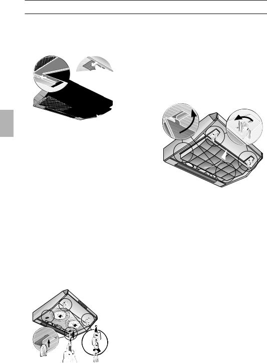
Retrait et mise en place des filtres à graisse en métal:
.be Filtres et entretienvandenborre
1. Poussez dans le sens. de la flèche le cran situé contrewwwchaque filtre à graisse puis abaissez les filtres.
Downloaded


2.Nettoyer les filtres à graisse.
3.Une fois nettoyés, remettez les filtres à graisse en place.
Filtre à charbon actif:
Ce filtre sert à retenir les substances odoriférantes lorsque la hotte recycle l'air.
Retirez d'abord les filtres à graisse (voir la section intitulée "Retrait et mise en place des filtres à graisse en métal).
1.Faites passer les vis dans les écrous à ailettes et dans les douilles, puis vissez les vis dans les doubles fonds, côté gauche et droit (opération nécessaire seulement lors du premier encastrement). Les vis, les écrous à ailettes et les douilles sont fournies avec le filtre à charbon actif.
2.A l'aide d'un tournevis ou assimilé, enfoncez vers l'intérieur les deux pattes situées contre le boîtier (opération nécessaire seulement lors du premier encastrement).
3.Mettez le filtre en place à l'arrière, rabattez-le vers le haut puis verrouillez-le à gauche et à droite par les écrous à ailettes.
Les pattes situées sur les côtés gauche et droit du filtre à charbon actif sont rentrées s'il faut monter le filtre dans une hotte aspirante en 50 cm de large.
Si la hotte fait 60 ou 90 cm de large, il faudra rabattre les pattes vers le haut.
Changement du filtre à charbon actif:
En service normal (1 à 2 heures par jour), il faut changer le filtre à charbon actif environ 1 fois par an.
Vous pouvez vous procurer ce filtre auprès de votre REVENDEUR SPECIALISE (voir la liste des accessoires en option).
N'utilisez que des filtres d'origine.
Vous garantirez ainsi un fonctionnement optimal de la hotte.
Mise au rebut de l'ancien filtre à charbon actif:
Les filtres à charbon actif ne contiennent pas de substances toxiques. Vous pouvez les mettre au rebut avec, par ex., les ordures ménagères.
28
 Loading...