


P8H61-MX R2.0
Table of contents
 Loading...
P8H61-MX Series
• P8H61-MX R2.0
• P8H61-MX USB3
Motherboard

E7982
First Edition
January 2013
Copyright © 2013 ASUSTeK COMPUTER INC. All Rights Reserved.
No part of this manual, including the products and software described in it, may be reproduced,
transmitted, transcribed, stored in a retrieval system, or translated into any language in any form or by any
means, except documentation kept by the purchaser for backup purposes, without the express written
permission of ASUSTeK COMPUTER INC. (“ASUS”).
Product warranty or service will not be extended if: (1) the product is repaired, modied or altered, unless
such repair, modication of alteration is authorized in writing by ASUS; or (2) the serial number of the
product is defaced or missing.
ASUS PROVIDES THIS MANUAL “AS IS” WITHOUT WARRANTY OF ANY KIND, EITHER EXPRESS
OR IMPLIED, INCLUDING BUT NOT LIMITED TO THE IMPLIED WARRANTIES OR CONDITIONS OF
MERCHANTABILITY OR FITNESS FOR A PARTICULAR PURPOSE. IN NO EVENT SHALL ASUS, ITS
DIRECTORS, OFFICERS, EMPLOYEES OR AGENTS BE LIABLE FOR ANY INDIRECT, SPECIAL,
INCIDENTAL, OR CONSEQUENTIAL DAMAGES (INCLUDING DAMAGES FOR LOSS OF PROFITS,
LOSS OF BUSINESS, LOSS OF USE OR DATA, INTERRUPTION OF BUSINESS AND THE LIKE),
EVEN IF ASUS HAS BEEN ADVISED OF THE POSSIBILITY OF SUCH DAMAGES ARISING FROM ANY
DEFECT OR ERROR IN THIS MANUAL OR PRODUCT.
SPECIFICATIONS AND INFORMATION CONTAINED IN THIS MANUAL ARE FURNISHED FOR
INFORMATIONAL USE ONLY, AND ARE SUBJECT TO CHANGE AT ANY TIME WITHOUT NOTICE,
AND SHOULD NOT BE CONSTRUED AS A COMMITMENT BY ASUS. ASUS ASSUMES NO
RESPONSIBILITY OR LIABILITY FOR ANY ERRORS OR INACCURACIES THAT MAY APPEAR IN THIS
MANUAL, INCLUDING THE PRODUCTS AND SOFTWARE DESCRIBED IN IT.
Products and corporate names appearing in this manual may or may not be registered trademarks or
copyrights of their respective companies, and are used only for identication or explanation and to the
owners’ benet, without intent to infringe.
Offer to Provide Source Code of Certain Software
This product contains copyrighted software that is licensed under the General Public License (“GPL”),
under the Lesser General Public License Version (“LGPL”) and/or other Free Open Source Software
Licenses. Such software in this product is distributed without any warranty to the extent permitted by the
applicable law. Copies of these licenses are included in this product.
Where the applicable license entitles you to the source code of such software and/or other additional data,
you may obtain it for a period of three years after our last shipment of the product, either
(1) for free by downloading it from http://support.asus.com/download
or
(2) for the cost of reproduction and shipment, which is dependent on the preferred carrier and the location
where you want to have it shipped to, by sending a request to:
ASUSTeK Computer Inc.
Legal Compliance Dept.
15 Li Te Rd.,
Beitou, Taipei 112
Taiwan
In your request please provide the name, model number and version, as stated in the About Box of the
product for which you wish to obtain the corresponding source code and your contact details so that we
can coordinate the terms and cost of shipment with you.
The source code will be distributed WITHOUT ANY WARRANTY and licensed under the same license as
the corresponding binary/object code.
This offer is valid to anyone in receipt of this information.
ASUSTeK is eager to duly provide complete source code as required under various Free Open Source
Software licenses. If however you encounter any problems in obtaining the full corresponding source
code we would be much obliged if you give us a notication to the email address gpl@asus.com, stating
the product and describing the problem (please DO NOT send large attachments such as source code
archives, etc. to this email address).
ii

Contents
Safety information ...................................................................................... vi
About this guide ........................................................................................ vii
P8H61-MX Series specications summary .............................................. ix
Chapter 1
Product introduction
1.1 Before you proceed ..................................................................... 1-1
1.2 Motherboard overview .................................................................
1.2.1 Placement direction ........................................................
1.2.2 Screw holes ....................................................................
1.2.3 Motherboard layout .........................................................
1.2.4 Layout contents ...............................................................
1.3 Central Processing Unit (CPU) ...................................................
1.3.1 Installing the CPU ...........................................................
1.3.2 Installing the CPU heatsink and fan ................................
1.3.3 Uninstalling the CPU heatsink and fan ...........................
1.4 System memory .........................................................................
1.4.1 Overview .......................................................................
1.4.2 Memory congurations ...................................................
1.4.3 Installing a DIMM ..........................................................
1.4.4 Removing a DIMM ........................................................
1.5 Expansion slots ..........................................................................
1.5.1 Installing an expansion card .........................................
1.5.2 Conguring an expansion card .....................................
1.5.3 PCI Express x1 slot .......................................................
1.5.4 PCI Express x16 slot .....................................................
1.6 Jumpers ......................................................................................
1.7 Connectors .................................................................................
1.7.1 Rear panel connectors ..................................................
1.7.2 Internal connectors .......................................................
1.8 Software support ........................................................................
1.8.1 Installing an operating system ......................................
1.8.2 Support DVD information ..............................................
1-2
1-2
1-2
1-3
1-4
1-5
1-5
1-8
1-9
1-10
1-10
1-11
1-17
1-17
1-18
1-18
1-18
1-18
1-18
1-19
1-20
1-20
1-21
1-26
1-26
1-26
iii

Contents
Chapter 2
BIOS information
2.1 Managing and updating your BIOS ............................................ 2-1
2.1.1 ASUS Update utility ........................................................
2.1.2 ASUS EZ Flash 2 ............................................................
2.1.3 ASUS BIOS Updater .......................................................
2.2 BIOS setup program ....................................................................
2.3 Main menu ....................................................................................
2.3.1 System Language [English] ............................................
2.3.2 System Date [Day xx/xx/xxxx] .........................................
2.3.3 System Time [xx:xx:xx] ...................................................
2.3.4 Security ...........................................................................
2.4 Ai Tweaker menu ........................................................................
2.4.1 Ai Overclock Tuner [Auto] ..............................................
2.4.2 ASUS MultiCore Enhancement [Enabled] ....................
2.4.3 Memory Frequency [Auto] .............................................
2.4.4 iGPU Max. Frequency [Auto] ........................................
2.4.5 GPU Boost [OK] ............................................................ 2-12
2.4.6 DRAM Timing Control ...................................................
2.4.7 CPU Power Management .............................................
2.5 Advanced menu .........................................................................
2.5.1 CPU Conguration ........................................................
2.5.2 PCH Conguration ........................................................
2.5.3 SATA Conguration .......................................................
2.5.4 System Agent Conguration .........................................
2.5.5 USB Conguration ........................................................
2.5.6 Onboard Devices Conguration ....................................
2.5.7 APM ..............................................................................
2.5.8 Network Stack ...............................................................
2.6 Monitor menu .............................................................................
2.6.1 CPU Temperature / MB Temperature
2.6.2 CPU / Chassis Fan Speed ...........................................
2.6.3 CPU Voltage, 3.3V Voltage, 5V Voltage, 12V Voltage ..
2.6.4 CPU Q-Fan Control [Enabled] ......................................
[xxxºC/xxxºF] ...... 2-23
2-1
2-2
2-3
2-5
2-9
2-9
2-9
2-9
2-9
2-11
2-11
2-12
2-12
2-12
2-12
2-13
2-14
2-15
2-17
2-18
2-18
2-19
2-20
2-20
2-21
2-22
2-23
2-23
2-23
iv

Contents
2.6.5 Chassis Q-Fan Control [Enabled] ................................. 2-24
2.6.6 Anti Surge Support [Enabled] .......................................
2.7 Boot menu ..................................................................................
2.7.1 Bootup NumLock State [On] .........................................
2.7.2 Full Screen Logo [Enabled] ...........................................
2.7.3 Wait for ‘F1’ If Error [Enabled] .......................................
2.7.4 Option ROM Messages [Force BIOS] ...........................
2.7.5 Setup Mode [EZ Mode] .................................................
2.7.6 UEFI/Legacy Boot [Enable both UEFI and Legacy] ......
2.7.7 PCI ROM Priority [Legacy ROM] ..................................
2.7.8 Boot Option Priorities ....................................................
2.7.9 Boot Override ................................................................
2.8 Tools menu .................................................................................
2.8.1 ASUS EZ Flash Utility ...................................................
2.8.2 ASUS SPD Information .................................................
2.8.3 ASUS O.C. Prole .........................................................
2.9 Exit menu ....................................................................................
Appendices
Notices .......................................................................................................A-1
ASUS contact information .......................................................................A-3
2-24
2-25
2-25
2-25
2-25
2-26
2-26
2-26
2-26
2-26
2-26
2-27
2-27
2-27
2-27
2-28
v

Safety information
Electrical safety
• To prevent electric shock hazard, disconnect the power cable from the electric outlet
before relocating the system.
• When adding or removing devices to or from the system, ensure that the power cables
for the devices are unplugged before the signal cables are connected. If possible,
disconnect all power cables from the existing system before you add a device.
• Before connecting or removing signal cables from the motherboard, ensure that all
power cables are unplugged.
• Seek professional assistance before using an adapter or extension cord. These devices
could interrupt the grounding circuit.
• Ensure that your power supply is set to the correct voltage in your area. If you are not
sure about the voltage of the electrical outlet you are using, contact your local power
company.
• If the power supply is broken, do not try to x it by yourself. Contact a qualied service
technician or your retailer.
Operation safety
•
Before installing the motherboard and adding devices on it, carefully read all the manuals
that came with the package.
•
Before using the product, ensure that all cables are correctly connected and the power
cables are not damaged. If you detect any damage, contact your dealer immediately.
•
To avoid short circuits, keep paper clips, screws, and staples away from connectors,
slots, sockets and circuitry.
•
Avoid dust, humidity, and temperature extremes. Do not place the product in any area
where it may become wet.
•
Place the product on a stable surface.
•
If you encounter technical problems with the product, contact a qualied service
technician or your retailer.
vi
About this guide
This user guide contains the information you need when installing and conguring the
motherboard.
How this guide is organized
This guide contains the following parts:
Chapter 1: Product introduction
•
This chapter describes the supported features of the motherboard.
• Chapter 2: BIOS information
This chapter provides a detailed guide to navigating and setting up the BIOS.
Conventions used in this guide
To ensure that you perform certain tasks properly, take note of the following symbols used
throughout this manual.
DANGER/WARNING: Information to prevent injury to yourself when completing
CAUTION: Information to prevent damage to the components when completing a
task.
IMPORTANT: Instructions you MUST follow to complete a task.
NOTE: Tips and additional information to help you complete a task.
a task.
vii

Where to nd more information
Refer to the following sources for additional information and for product and software
updates.
1. ASUS websites
The ASUS website provides updated information on ASUS hardware and software
products. Refer to the ASUS contact information.
2. Optional documentation
Your product package may include optional documentation, such as warranty yers,
that may have been added by your dealer. These documents are not part of the
standard package.
Typography
Bold text Indicates a menu or an item to select.
Italic
s Used to emphasize a word or a phrase.
<Key> Keys enclosed in the less-than and greater-than sign
<Key1> + <Key2> + <Key3> If you must press two or more keys simultaneously, the
means that you must press the enclosed key.
Example: <Enter> means that you must press the Enter
or Return key.
key names are linked with a plus sign (+). Example:
<Ctrl> + <Alt> + <Del>
viii
P8H61-MX Series specications summary
CPU LGA1155 socket for Intel® 3rd/2nd Generation Core™ i7 / i5 / i3 /
Chipset Intel® H61 Express Chipset
Memory 2 x DIMMs, max. 16GB DDR3 2200 (O.C.) / 2133 (O.C.) / 2000
Graphics Multi-VGA Output Support: DVI-D and D-SUB Ports
Expansion slots 1 x PCI Express 3.0*/2.0 x16 slot
Storage
LAN
Audio VIA VT1708S 8-channel High Denition Audio CODEC
USB P8H61-MX R2.0
Pentium® / Celeron® processors
Supports 22/32nm CPU
*Refer to www.asus.com for Intel® CPU support list.
(O.C.) / 1866 (O.C.) / 1600 / 1333 / 1066 MHz, non-ECC, un-
buffered memory*
Dual-channel memory architecture
*When you install memory of 4GB capacity or more, Windows®
32-bit operating system may only recognize less than 3GB. We
recommend a maximum of 3GB system memory if you are using
a Windows® 32-bit operating system.
**DDR3 1600 MHz and higher memory frequency is supported by
Intel® 3rd generation processors.
***Refer to www.asus.com for the latest Memory QVL (Qualied
Vendor List).
DVI with Max. Resolution: 1920 x 1200 @60Hz
D-SUB with Max. Resolution: 2048 x 1536 @75Hz
2 x PCI Express 2.0 x1 slots
*PCIe 3.0 speed is supported by Intel® 3rd generation processors.
Intel® H61 Express Chipset:
- 4 x Serial ATA 3.0 Gb/s connectors
Realtek® 8111F-VB-CG Gigabit LAN controller
- Supports Multi-Streaming
Intel® H61 Express Chipset
- 10 x USB 2.0/1.1 ports (4 ports at mid-board, 6 ports at rear)
P8H61-MX USB3
Intel® H61 Express Chipset
- 8 x USB 2.0/1.1 ports (4 ports at mid-board, 4 ports at rear)
ASMedia® ASM1042 controller
- 2 x USB 3.0 ports (2 ports at rear)
(continued on the next page)
ix

P8H61-MX Series specications summary
ASUS unique features ASUS MyLogo 2™
ASUS Anti-Surge Protection
ASUS UEFI BIOS
ASUS EZ Flash 2
ASUS FanXpert
ASUS AI Charger (P8H61-MX R2.0 only)
ASUS AI Charger+ (P8H61-MX USB3 only)
ASUS Q-Fan 2
ASUS CrashFree BIOS 3
ASUS GPU Boost
Rear panel ports 1 x PS/2 keyboard / mouse combo port
1 x DVI port
1 x D-Sub port
1 x LAN (RJ-45) port
P8H61-MX R2.0:
- 6 x USB 2.0/1.1 ports
P8H61-MX USB3:
- 4 x USB 2.0/1.1 ports
- 2 x USB 3.0 ports
3 x Audio jacks
Internal connectors/
switches/ buttons
BIOS features 64 Mb Flash ROM, UEFI BIOS, PnP, DMI v2.0, WfM 2.0, ASUS
Manageability
Accessories 2 x Serial ATA 3.0Gb/s cables
Support DVD Drivers
Form factor
2 x USB 2.0/1.1 connectors support additional 4 USB 2.0/1.1
ports
4 x SATA 3.0 Gb/s connectors
1 x CPU fan connector
1 x Chassis fan connector
1 x Front panel audio connector
1 x Speaker header
1 x Front panel header
1 x 24-pin ATX power connector
1 x 4-pin ATX 12V power connector
EZ Flash 2, ASUS CrashFree BIOS 3, SMBIOS v2.6, ACPI v2.0a,
Multi-language BIOS
WOL, PME Wake Up, PXE
1 x I/O shield
1 x User Manual
1 x Support DVD
ASUS Utilities
ASUS Update
Anti-virus software (OEM version)
uATX form factor: 9.6 in x 7.2 in (24.4 cm x 18.3 cm)
* Specications are subject to change without notice.
x
Chapter 1
SB_PWR
ON
Standby Power Powered Off
OFF
P8H61-MX R2.0
P8H61-MX Series Onboard LED
Product introduction
Thank you for buying an ASUS® P8H61-MX Series motherboard!
Before you start installing the motherboard and adding hardware components, check the
items in your motherboard package. Refer to page x for the list of included accessories.
• If any of the items is damaged or missing, contact your retailer.
• ASUS P8H61-MX Series motherboards include P8H61-MX R2.0 and P8H61-MX USB3
models. The layout varies between the two models. The layout illustrations in this user
manual are for P8H61-MX R2.0 only.
1.1 Before you proceed
Take note of the following precautions before you install motherboard components or change
any motherboard settings.
• Unplug the power cord from the wall socket before touching any component.
• Before handling components, use a grounded wrist strap or touch a safely grounded
object or a metal object, such as the power supply case, to avoid damaging them due to
static electricity.
• Hold components by the edges to avoid touching the ICs on them.
• Whenever you uninstall any component, place it on a grounded antistatic pad or in the
bag that came with the component.
• Before you install or remove any component, ensure that the ATX power supply is
switched off or the power cord is detached from the power supply. Failure to do so may
cause severe damage to the motherboard, peripherals, or components.
Standby Power LED
The motherboard comes with a standby power LED that lights up to indicate that the system
is ON, in sleep mode, or in soft-off mode. This is a reminder that you should shut down
the system and unplug the power cable before removing or plugging in any motherboard
component. The illustration below shows the location of the onboard LED.
1-1Chapter 1: Product introduction

P8H61-MX R2.0
1.2 Motherboard overview
Before you install the motherboard, study the conguration of your chassis to ensure that the
motherboard ts.
Unplug the power cord before installing or removing the motherboard. Failure to do so can
cause you physical injury and damage motherboard components.
1.2.1 Placement direction
When installing the motherboard, place it into the chassis in the correct orientation. The edge
with external ports goes to the rear part of the chassis as indicated in the image below.
1.2.2 Screw holes
Place six screws into the holes indicated by circles to secure the motherboard to the chassis.
Do not overtighten the screws! Doing so can damage the motherboard.
Place this side
towards the rear
of the chassis
ASUS P8H61-MX Series1-2
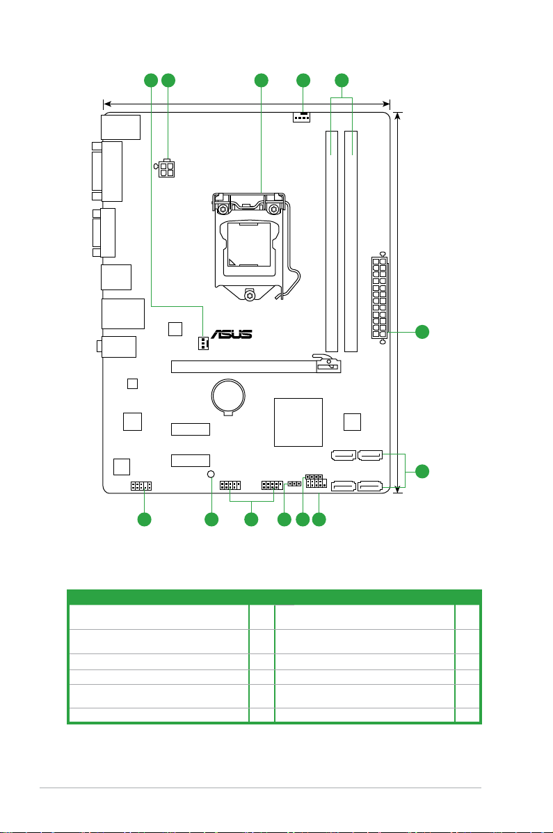
1.2.3 Motherboard layout
P8H61-MX R2.0
PCIEX16
PCIEX1_1
PCIEX1_2
F_PANEL
SPEAKER
CLRTC
USB78USB910
AAFP
ATX12V
EATXPWR
CPU_FAN
CHA_FAN
Lithium Cell
CMOS Power
Super
I/O
VIA
VT1708S
RTL
8111F
64Mb
BIOS
SB_PWR
24.4cm(9.6in)
LGA1155
Intel
®
H61
DDR3 DIMM_A1 (64bit, 240-pin module)
DDR3 DIMM_B1 (64bit, 240-pin module)
SATA3G_1
SATA3G_2
SATA3G_3
SATA3G_4
AUDIO
KB_USB56
LAN_USB12
USB34
18.3cm(7.2in)
VGA
DVI
321 41
2
67891011
5
1-3Chapter 1: Product introduction
P8H61-MX USB3
PCIEX16
PCIEX1_1
PCIEX1_2
F_PANEL
SPEAKER
CLRTC
USB78USB910
AAFP
ATX12V
EATXPWR
CPU_FAN
CHA_FAN
Lithium Cell
CMOS Power
Super
I/O
VIA
VT1708S
ASM
1042
RTL
8111F
64Mb
BIOS
SB_PWR
24.4cm(9.6in)
LGA1155
Intel
®
H61
DDR3 DIMM_A1 (64bit, 240-pin module)
DDR3 DIMM_B1 (64bit, 240-pin module)
SATA3G_1
SATA3G_2
SATA3G_3
SATA3G_4
AUDIO
KB_USB56
LAN_USB12
USB3_12
18.3cm(7.2in)
VGA
DVI
321 41
2
67891011
5
1.2.4 Layout contents
Connectors/Jumpers/Slots/LED Page Connectors/Jumpers/Slots/LED Page
CPU and chassis fan connectors (4-pin
1.
CPU_FAN, 3-pin CHA_FAN)
ATX power connectors (24-pin EATXPWR,
2.
4-pin ATX12V)
3. Intel® LGA1155 CPU socket 1-4 9. USB connectors (USB78, USB910) 1-19
4. DDR3 DIMM slots 1-9 10. Standby power LED (SB_PWR) 1-1
Intel® H61 Serial ATA 3.0Gb/s connectors
5.
(7-pin SATA3G_1/2/3/4)
6. System panel connector (10-1 pin PANEL) 1-21
1-19 7. Speaker connector (4-pin SPEAKER) 1-20
1-18 8. Clear RTC RAM (3-pin CLRTC) 1-15
1-20 11. Front panel audio connector (10-1 pin AAFP) 1-17
ASUS P8H61-MX Series1-4
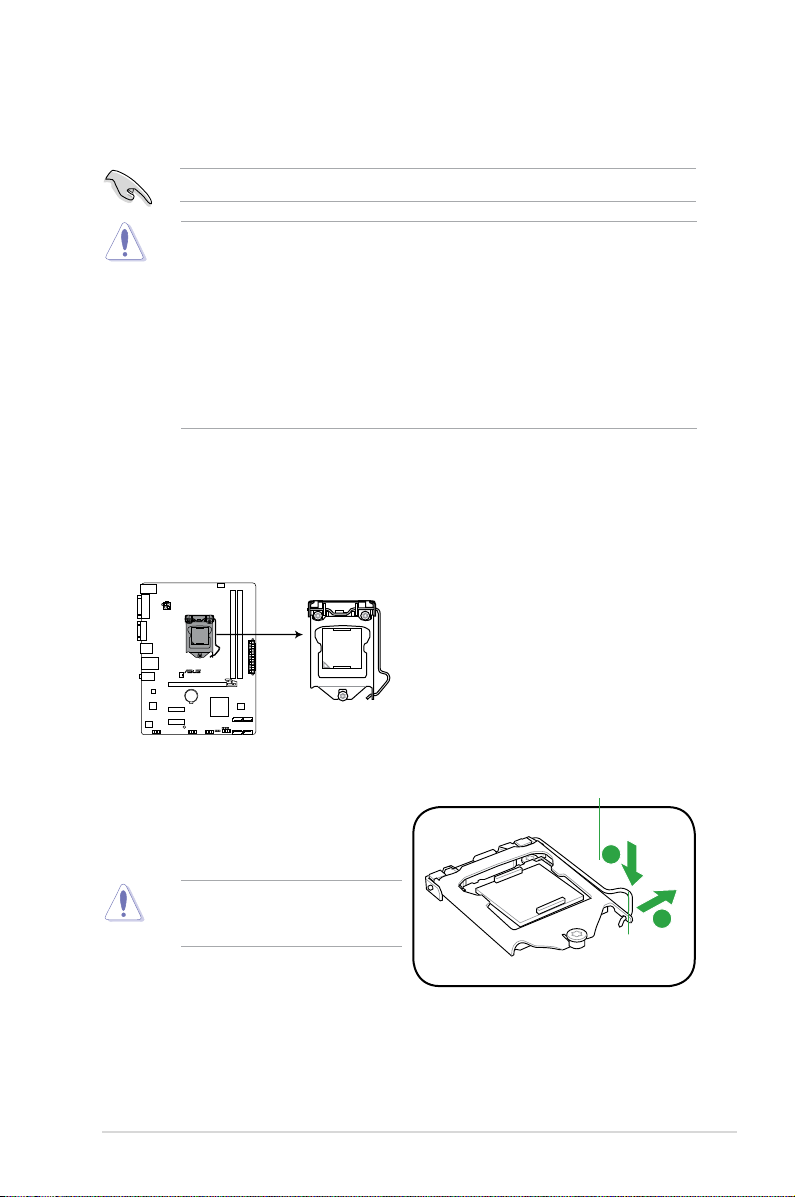
1.3 Central Processing Unit (CPU)
A
B
P8H61-MX R2.0
P8H61-MX Series CPU socket LGA1155
The motherboard comes with a surface mount LGA1155 socket designed for Intel®
processors.
Unplug all power cables before installing the CPU.
• Upon purchase of the motherboard, ensure that the PnP cap is on the socket and the
socket contacts are not bent. Contact your retailer immediately if the PnP cap is missing,
or if you see any damage to the PnP cap/socket contacts/motherboard components.
ASUS will shoulder the cost of repair only if the damage is shipment/transit-related.
• Keep the cap after installing the motherboard. ASUS will process Return Merchandise
Authorization (RMA) requests only if the motherboard comes with the cap on the
LGA1155 socket.
• The product warranty does not cover damage to the socket contacts resulting from
incorrect CPU installation/removal, or misplacement/loss/incorrect removal of the PnP
cap.
1.3.1 Installing the CPU
To install a CPU:
1. Locate the CPU socket on the motherboard.
2. Press the load lever with your thumb (A),
and then move it to the right (B) until it is
released from the retention tab.
To prevent damage to the socket pins,
do not remove the PnP cap unless
you are installing a CPU.
Load lever
Retention tab
1-5Chapter 1: Product introduction
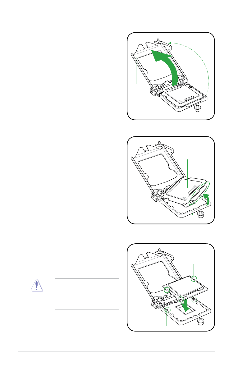
3. Lift the load lever in the direction of the
arrow until the load plate is completely
lifted.
4. Remove the PnP cap from the CPU
socket by lifting the tab only.
Load plate
PnP cap
5. Position the CPU over the socket,
ensuring that the gold triangle is on the
bottom-left corner of the socket, and
then t the socket alignment keys into
the CPU notches.
The CPU ts in only one correct
orientation. DO NOT force the CPU
into the socket to prevent bending
the connectors on the socket and
damaging the CPU!
CPU notches
Gold
triangle
mark
Alignment keys
ASUS P8H61-MX Series1-6
B
A
C
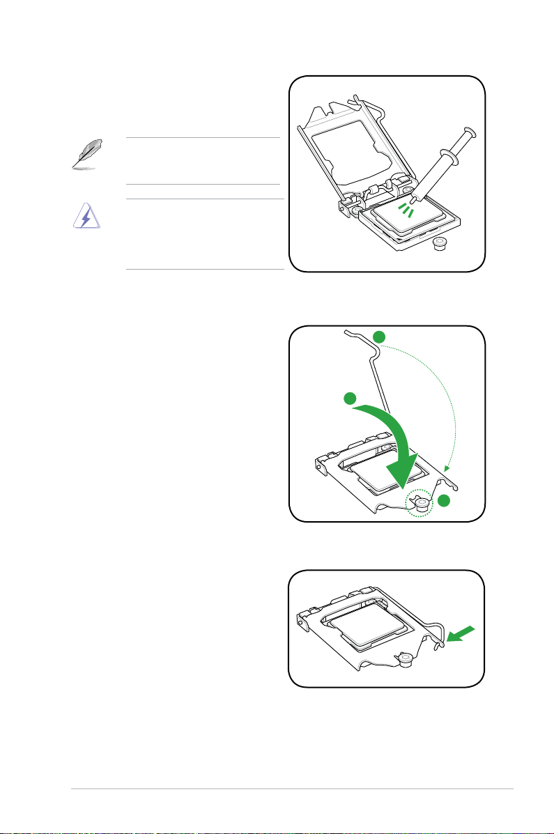
6. Apply some Thermal Interface Material
to the exposed area of the CPU that the
heatsink will be in contact with, ensuring
that it is spread in an even thin layer.
Some heatsinks come with preapplied thermal paste. If so, skip this
step.
The Thermal Interface Material is
toxic and inedible. DO NOT eat it. If
it gets into your eyes or touches your
skin, wash it off immediately, and seek
professional medical help.
7. Close the load plate (A), and then push
down the load lever (B), ensuring that
the front edge of the load plate slides
under the retention knob (C).
8. Insert the load lever under the retention
tab.
1-7Chapter 1: Product introduction
1.3.2 Installing the CPU heatsink and fan
The Intel® LGA1155 processor requires a specially designed heatsink and fan assembly to
ensure optimum thermal condition and performance.
•
When you buy a boxed Intel® processor, the package includes the CPU fan and
heatsink assembly. If you buy a CPU separately, ensure that you use only Intel®-certied
multi-directional heatsink and fan.
• Your Intel
• Use an LGA1155-compatible CPU heatsink and fan assembly only. The LGA1155 socket
If you purchased a separate CPU heatsink and fan assembly, ensure that you have
properly applied Thermal Interface Material to the CPU heatsink or CPU before you install
the heatsink and fan assembly.
Ensure that you have installed the motherboard to the chassis before you install the CPU
fan and heatsink assembly.
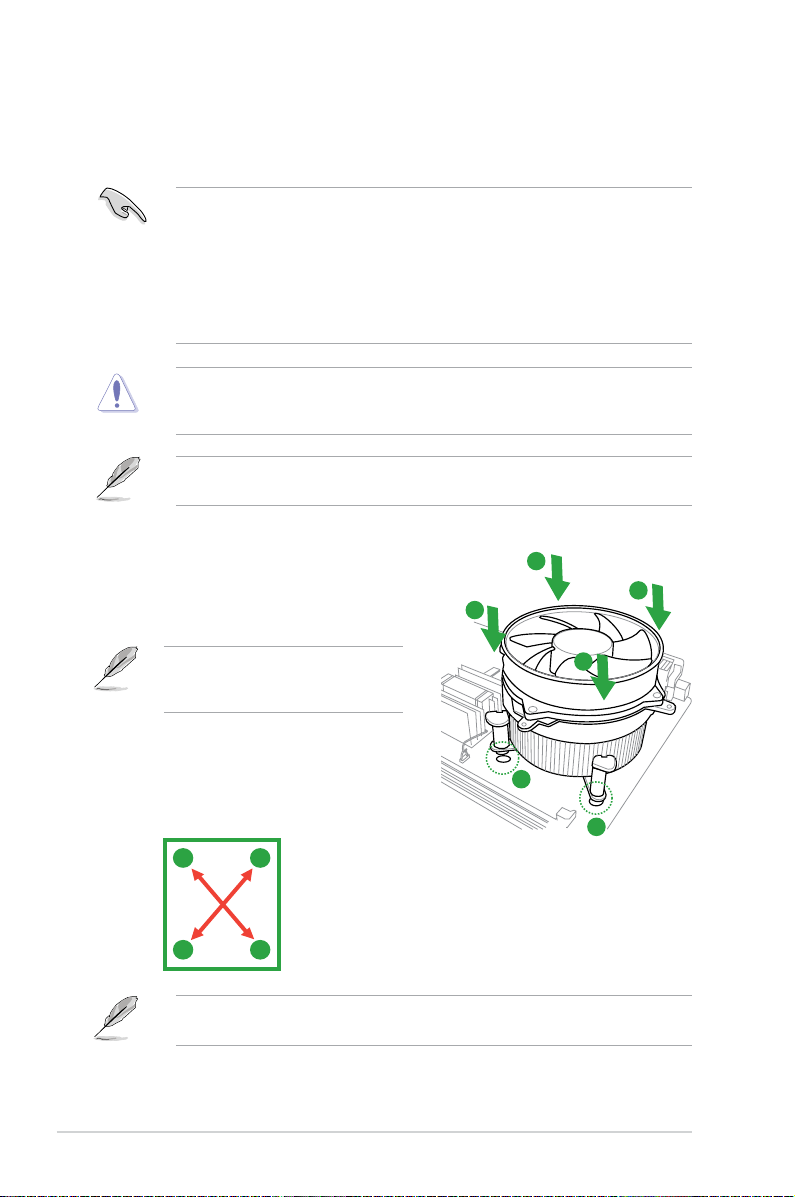
To install the CPU heatsink and fan:
1. Place the heatsink on top of the installed
CPU, ensuring that the four fasteners
match the holes on the motherboard.
®
LGA1155 heatsink and fan assembly comes in a push-pin design and
requires no tool to install.
is incompatible with the LGA775 and LGA1366 sockets in size and dimension.
A
B
B
Orient the heatsink and fan assembly
such that the CPU fan cable is closest to
the CPU fan connector.
2. Push down two fasteners at a time in a
diagonal sequence to secure the heatsink
and fan assembly in place.
A
B
The type of CPU heatsink and fan assembly may differ, but the installation steps and
functions should remain the same. The illustration above is for reference only.
B
A
A
1
1
ASUS P8H61-MX Series1-8
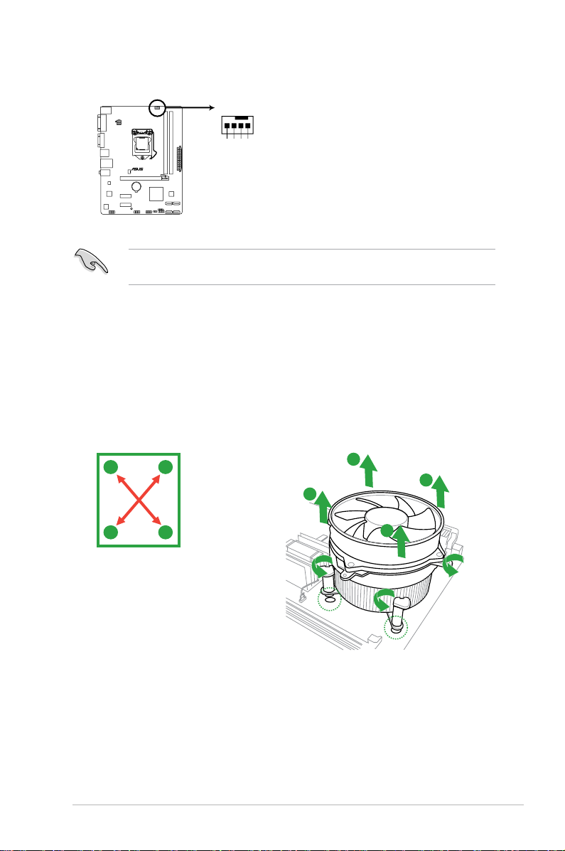
3. Connect the CPU fan cable to the connector on the motherboard labeled CPU_FAN.
CPU_FAN
CPU FAN PWM
CPU FAN IN
CPU FAN PWR
GND
P8H61-MX R2.0
P8H61-MX Series CPU fan connector
Do not forget to connect the CPU fan connector! Hardware monitoring errors can occur if
you fail to plug this connector.
1.3.3 Uninstalling the CPU heatsink and fan
To uninstall the CPU heatsink and fan:
1. Disconnect the CPU fan cable from the connector on the motherboard.
2. Rotate each fastener counterclockwise.
3. Pull up two fasteners at a time in a diagonal sequence to disengage the heatsink and
fan assembly from the motherboard.
A
B
B
A
A
B
B
A
1-9Chapter 1: Product introduction
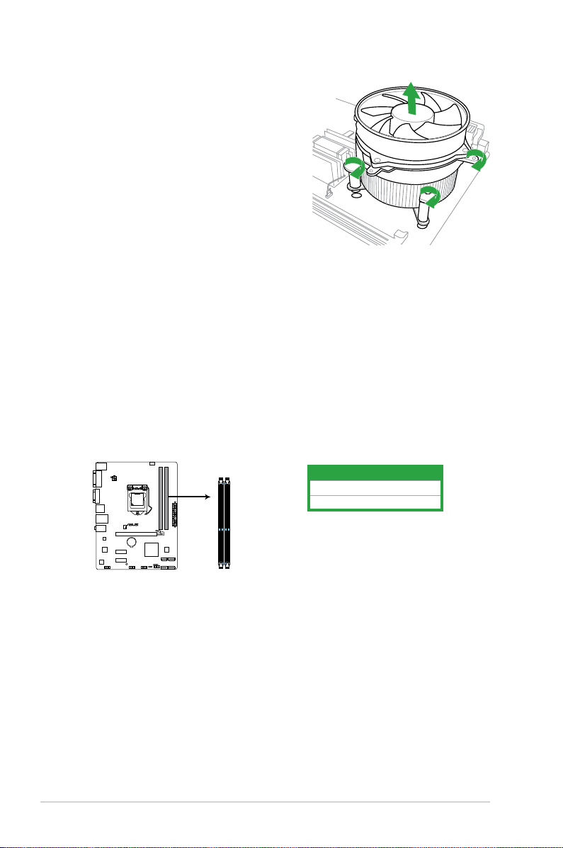
4. Carefully remove the heatsink and fan
P8H61-MX R2.0
P8H61-MX Series 240-pin DDR3 DIMM sockets
DIMM_A1
DIMM_B1
assembly from the motherboard.
5. Rotate each fastener clockwise to ensure
correct orientation when reinstalling.
1.4 System memory
1.4.1 Overview
The motherboard comes with two Double Data Rate 3 (DDR3) Dual Inline Memory Modules
(DIMM) sockets.
A DDR3 module has the same physical dimensions as a DDR2 DIMM but is notched
differently to prevent installation on a DDR2 DIMM socket. DDR3 modules are developed for
better performance with less power consumption.
The gure illustrates the location of the DDR3 DIMM sockets:
Channel Sockets
Channel A DIMM_A1
Channel B DIMM_B1
ASUS P8H61-MX Series1-10
1.4.2 Memory congurations
You may install 1GB, 2GB, 4GB and 8GB unbuffered non-ECC DDR3 DIMMs into the DIMM
sockets.
• You may install varying memory sizes in Channel A and Channel B. The system maps
the total size of the lower-sized channel for the dual-channel conguration. Any excess
memory from the higher-sized channel is then mapped for single-channel operation.
• Always install DIMMs with the same CAS latency. For optimal compatibility, we
recommend that you install memory modules of the same version or date code (D/C)
from the same vendor. Check with the retailer to get the correct memory modules.
• Due to the memory address limitation on 32-bit Windows
or more memory on the motherboard, the actual usable memory for the OS can be
about 3GB or less. For effective use of memory, we recommend that you do any of the
following:
- Use a maximum of 3GB system memory if you are using a 32-bit Windows
- Install a 64-bit Windows® OS when you want to install 4GB or more on the
motherboard.
• This motherboard does not support DIMMs that use 512Mb (64MB) chips or less.
• Memory modules with memory frequency higher than 2133 MHz and its corresponding
timing or the loaded X.M.P. Prole is not the JEDEC memory standard. The stability
and compatibility of these memory modules depend on the CPU’s capabilities and other
installed devices.
• The maximum 16GB memory capacity can be supported with 8GB or above DIMMs.
ASUS will update the memory QVL once the DIMMs are available in the market.
• The default memory operation frequency is dependent on its Serial Presence Detect
(SPD), which is the standard way of accessing information from a memory module.
Under the default state, some memory modules for overclocking may operate at a
lower frequency than the vendor-marked value. To operate at the vendor-marked or at a
higher frequency, refer to section 2.4 Ai Tweaker menu for manual memory frequency
adjustment.
• For system stability, use a more efcient memory cooling system to support a full
memory load (2 DIMMs) or overclocking condition.
®
OS, when you install 4GB
®
OS.
P8H61-MX Series Motherboard Qualied Vendors Lists (QVL)
DDR3-1066 MHz capability
Vendors Part No. Size
Crucial CT12864BA1067.8FF 1GB SS Micron 9GF22D9KPT 7 - • •
Crucial CT25664BA1067.16FF 2GB DS Micron 9HF22D9KPT 7 - • •
ELPIDA EBJ10UE8EDF0-AE-F 1GB SS ELPIDA J1108EDSE-DJ-F - 1.35V(low voltage) • •
ELPIDA EBJ21UE8EDF0-AE-F 2GB DS ELPIDA J1108EDSE-DJ-F - 1.35V(low voltage) • •
KINGSTON KVR1066D3N7/1G(low prole) 1GB SS ELPIDA J1108BFSE-DJ-F 7 1.5V • •
KINGSTON KVR1066D3N7/2G 2GB DS ELPIDA J1108BDSE-DJ-F 7 1.5V • •
KINGSTON KVR1066D3N7/4G 4GB DS Hynix H5TQ2G83AFR 7 1.5V • •
Micron MT8JTF12864AZ-1G1F1 1GB SS Micron 9GF22D9KPT 7 - • •
Micron MT16JTF25664AZ-1G1F1 2GB DS Micron 9HF22D9KPT 7 - • •
SS/
Chip Brand Chip NO. Timing Voltage
DS
(continued on the next page)
DIMM socket
support (Optional)
A* B*
1-11Chapter 1: Product introduction
Loading...