


K8S-LA
(Salmon)
Motherboard

Contents
K8S-LA specifications summary ......................................................... |
iii |
||
1. |
Motherboard layout ................................................................. |
1 |
|
2. |
Central Processing Unit (CPU) ................................................. |
2 |
|
3. |
System memory ...................................................................... |
4 |
|
4. |
Expansion slots ........................................................................ |
6 |
|
5. |
Jumpers |
................................................................................... |
8 |
6. |
Connectors .............................................................................. |
9 |
|
|
6.1 |
Rear panel connectors ............................................... |
9 |
|
6.2 |
Internal connectors.................................................. |
11 |
ii

K8S-LA specifications summary
C P U |
Socket 754 for AMD Athlon® 64 processor |
|
with HyperTransport support |
|
|
Chipset |
SiS760 |
|
SiS964 |
|
|
Front Side Bus (FSB) |
1600 MT/s @ 800 MHz |
|
|
Memory |
2 x 184-pin DDR DIMM sockets support unbuffered |
|
non-ECC 2 GB 400/333/266 MHz DDR SDRAM |
|
memory modules |
|
|
Expansion slots |
3 x PCI slots |
|
1 x AGP slot |
|
|
Storage |
2 x Ultra DMA 100/66/33 |
|
2 x Serial ATA |
|
|
Audio |
Realtek® ALC658C 6-channel CODEC |
|
|
L A N |
Realtek® RTL8201CL LAN PHY Fast Ethernet |
|
LAN controller |
|
|
IEEE 1394 |
VIA VT6307 supports two IEEE 1394a ports |
|
|
PC health monitoring |
ASUS A8000 for CPU/Chassis fan control and CPU |
|
temperature monitoring |
|
|
BIOS features |
4 Mb LPC EEPROM |
|
Award BIOS with enhanced ACPI, DMI, Green, and |
|
PnP Features Plus |
|
|
Form factor |
Micro-ATX form factor: 9.6 in x 9.6 in |
|
|
Rear panel |
1 x PS/2 mouse port |
|
1 x Parallel port |
|
1 x IEEE 1394a port |
|
1 x LAN (RJ-45) port |
|
6-channel audio ports |
|
4 x USB 2.0 ports |
|
1 x VGA port |
|
1 x Serial port |
|
1 x PS/2 keyboard port |
|
|
|
(continued on the next page) |
iii

K8S-LA specifications summary
Internal connectors 1 x Floppy disk drive connector 2 x IDE connectors
1 x 20-pin ATX power connector
1 x 4-pin ATX 12V power connector
2 x Serial ATA connectors
1 x IEEE 1394a connector
2 x USB 2.0 connectors support for four additional USB 2.0 ports
1 x CPU fan connector
1 x Chassis fan connector
1 x CD in connector
1 x AUX connector
1 x SPDIF out connector
1 x Front panel audio connector System panel connector
* Specifications are subject to change without notice
iv

1.Motherboard layout
24.5cm (9.64in)
PS/2 |
|
|
|
T: Mouse |
|
|
|
B: Keyboard |
|
|
|
COM1 |
DDR XMM2 (64/72 bit, 184-pin module) |
|
|
|
|
||
|
|
DDR XMM1 (64/72 bit, 184-pin module) |
|
|
PORT |
|
|
|
PARALLEL |
CHA_FAN1 |
|
|
|
|
|
VGA |
|
|
|
Bottom: |
Top: |
|
|
USB1 1394 |
|
|
|
USB2 |
|
|
|
Bottom: |
Top: |
Socket 754 |
SiS |
|
|||
USB1 |
RJ-45 |
|
760 |
USB2 |
|
||
|
|
|
|
|
|
|
|
|
Top:Line In |
|
|
|
|
|
|
|
Center:Line Out |
|
|
|
|
K8S-LA |
|
|
Below:Mic In |
|
|
|
|
||
|
|
|
|
|
Realtek |
|
|
|
|
|
|
|
VT6307 |
|
1.5V AGP SLOT ONLY |
|
|
|
|
|
|
|
|
|
|
|
|
|
|
|
|
PCI 1
SiS
964
PCI 2
ALC658
PCI 3


 J3
J3
CD1 |
AUX1 SPDIF1 |
USB2 |
USB1 |
|
|
Clear Password |
Super |
I/O |
J6 |
|
|
||
|
|
|
|
J7 |
|
|
|
FLOPPY1
FAN1 |
ATXPWR1 |
IDESECONDARY |
CPU_ |
||
ATX12V1 |
|
|
BATY1 |
|
|


 SATA2
SATA2


 SATA1
SATA1
|
|
|
|
|
|
4Mb |
|
|
IDE |
||||
|
|
|
|
|
|
BIOS |
|
|
|||||
|
|
|
|
|
|
|
|
PRIMARY |
|||||
|
|
|
|
|
|
|
|
|
|||||
|
|
|
|
|
|
BUZZ1 |
|||||||
IEEE1394_1 |
F_PANEL1 |
||||||||||||
|
|
|
|
|
|
|
|
|
|
|
|
|
|
|
|
|
|
|
|
|
|
|
|
|
|
|
|
CMOS Clear
24.5cm (9.64in)
ASUS K8S-LA (Salmon) |
1 |

2.Central Processing Unit (CPU)
The motherboard comes with a surface mount 754-pin Zero Insertion Force (ZIF) socket designed for the AMD Athlon™ 64 processor. Take note of the marked corner (with gold triangle) on the CPU. This mark should match a specific corner on the socket to ensure correct installation.
Incorrect installation of the CPU into the socket may bend the pins and severely damage the CPU!
2.1 Installing the CPU
Follow these steps to install a CPU.
1.Locate the 754-pin ZIF socket on the motherboard.
K8S-LA
Gold Arrow 
K8S-LA CPU Socket 754
2.Unlock the socket by pressing the lever sideways, then lift it up to a 90°-100° angle.
S o l e
Make sure that the socket lever is lifted up to 90°-100° angle, otherwise the CPU does not fit in completely.
2 |
ASUS K8S-LA (Salmon) |
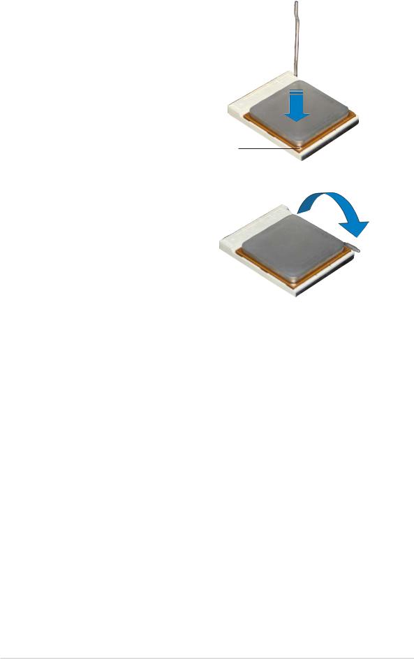
3.Position the CPU above the socket such that the CPU corner with the gold triangle matches the socket corner with a small triangle.
4.Carefully insert the CPU into the socket until it fits in place.
G o l d triangle
5.When the CPU is in place, push down the socket lever to secure the CPU. The lever clicks on the side tab to indicate that it is locked.
6.Install a CPU heatsink and fan following the instructions that came with the heatsink package.
7.Connect the CPU fan cable to the CPU_FAN connector on the motherboard.
ASUS K8S-LA (Salmon) |
3 |

3.System memory
The motherboard comes with two Double Data Rate (DDR) Dual Inline Memory Module (DIMM) sockets. These sockets support up to 2 GB system memory using 184-pin unbuffered non-ECC PC3200/PC2700/PC2100/ PC1600 double-sided DDR DIMMs.
The following figure illustrates the location of the DDR DIMM sockets.
|
|
|
|
|
|
|
|
|
|
|
|
|
|
|
|
104 Pins |
|
80 Pins |
|||||
|
|
|
|
|
|
|
|
|
|
|
|
|
|
|
|
|
|||||||
|
|
|
|
|
|
|
|
|
|
|
|
|
|
|
|
|
|
|
|
|
|
|
|
|
|
|
|
|
|
|
|
|
|
|
|
|
|
|
|
|
|
|
|
|
|
|
|
|
|
|
|
|
|
|
|
|
|
|
|
|
|
|
|
|
|
|
|
|
|
|
|
|
|
|
|
|
|
|
|
|
|
|
|
|
|
|
|
|
|
|
|
|
|
|
|
|
|
|
|
|
|
|
|
|
|
|
|
|
|
|
|
|
|
|
|
|
|
|
|
|
|
|
|
|
|
|
|
|
|
|
|
|
|
|
|
|
|
|
|
|
|
|
|
|
|
|
|
|
|
|
|
|
|
|
|
|
|
|
|
|
|
|
|
|
|
|
|
|
|
|
|
|
|
|
|
|
|
|
|
|
|
|
|
|
|
|
|
|
|
|
|
K8S-LA
K8S-LA 184-pin DDR DIMM sockets
Memory configurations
You can install 128 MB, 256 MB, 512 MB, and 1 GB DDR DIMMs into the DIMM sockets using the memory configurations in this section.
A DDR DIMM is keyed with a notch so that it fits in only one direction. DO NOT force a DIMM into a socket to avoid damaging the DIMM.
4 |
ASUS K8S-LA (Salmon) |
 Loading...