


KNPA-U16 |
User Guide |

E14767
First Edition
September 2018
Copyright © 2018 ASUSTeK COMPUTER INC. All Rights Reserved.
No part of this manual, including the products and software described in it, may be reproduced, transmitted, transcribed, stored in a retrieval system, or translated into any language in any form or by any means, except documentation kept by the purchaser for backup purposes, without the express written permission of ASUSTeK COMPUTER INC. (“ASUS”).
Product warranty or service will not be extended if: (1) the product is repaired, modified or altered, unless such repair, modification of alteration is authorized in writing by ASUS; or (2) the serial number of the product is defaced or missing.
ASUS PROVIDES THIS MANUAL “AS IS” WITHOUT WARRANTY OF ANY KIND, EITHER EXPRESS OR IMPLIED, INCLUDING BUT NOT LIMITED TO THE IMPLIED WARRANTIES OR CONDITIONS OF MERCHANTABILITY OR FITNESS FOR A PARTICULAR PURPOSE. IN NO EVENT SHALL ASUS, ITS DIRECTORS, OFFICERS, EMPLOYEES OR AGENTS BE LIABLE FOR ANY INDIRECT, SPECIAL, INCIDENTAL, OR CONSEQUENTIAL DAMAGES (INCLUDING DAMAGES FOR LOSS OF PROFITS, LOSS OF BUSINESS, LOSS OF USE OR DATA, INTERRUPTION OF BUSINESS AND THE LIKE), EVEN IF ASUS HAS BEEN ADVISED OF THE POSSIBILITY OF SUCH DAMAGES ARISING FROM ANY DEFECT OR ERROR IN THIS MANUAL OR PRODUCT.
SPECIFICATIONS AND INFORMATION CONTAINED IN THIS MANUAL ARE FURNISHED FOR INFORMATIONAL USE ONLY, AND ARE SUBJECT TO CHANGE AT ANY TIME WITHOUT NOTICE, AND SHOULD NOT BE CONSTRUED AS A COMMITMENT BY ASUS. ASUS ASSUMES NO RESPONSIBILITY OR LIABILITY FOR ANY ERRORS OR INACCURACIES THAT MAY APPEAR IN THIS MANUAL, INCLUDING THE PRODUCTS AND SOFTWARE DESCRIBED IN IT.
Products and corporate names appearing in this manual may or may not be registered trademarks or copyrights of their respective companies, and are used only for identification or explanation and to the owners’ benefit, without intent to infringe.
ii

Contents
Safety information...................................................................................................... |
vi |
About this guide......................................................................................................... |
vii |
KNPA-U16 specifications summary.......................................................................... |
ix |
Chapter 1: Product Introduction
1.1 |
Welcome!..................................................................................................... |
1-2 |
1.2 |
Package contents....................................................................................... |
1-2 |
1.3 |
Serial number label..................................................................................... |
1-2 |
Chapter 2: Hardware Information
2.1 |
Before you proceed.................................................................................... |
2-2 |
|
2.2 |
Motherboard overview............................................................................... |
2-3 |
|
|
2.2.1 |
Placement direction ..................................................................... |
2-3 |
|
2.2.2 |
Screw holes ................................................................................. |
2-3 |
|
2.2.3 |
Motherboard layout ...................................................................... |
2-4 |
2.3 |
Central Processing Unit (CPU).................................................................. |
2-6 |
|
|
2.3.1 |
Installing the CPU ........................................................................ |
2-6 |
2.4 |
System memory........................................................................................ |
2-10 |
|
|
2.4.1 |
Overview .................................................................................... |
2-10 |
|
2.4.2 |
Memory Configurations .............................................................. |
2-10 |
|
2.4.3 |
Installing a DIMM on a single clip DIMM socket ........................ |
2-11 |
2.5 |
Expansion slots........................................................................................ |
2-12 |
|
|
2.5.1 |
Installing an expansion card ...................................................... |
2-12 |
|
2.5.2 |
Configuring an expansion card .................................................. |
2-12 |
|
2.5.3 |
Interrupt assignments ................................................................ |
2-13 |
2.6 |
Jumpers |
..................................................................................................... |
2-15 |
2.7 |
Onboard ...........................................................................................LEDs |
2-19 |
|
2.8 |
Connectors................................................................................................ |
2-22 |
|
|
2.8.1 ............................................................... |
Rear panel connectors |
2-22 |
|
2.8.2 .................................................................... |
Internal connectors |
2-23 |
Chapter 3: Powering Up
3.1 |
Starting up for the first time...................................................................... |
3-2 |
|
3.2 |
Powering off the computer........................................................................ |
3-3 |
|
|
3.2.1 |
Using the OS shut down function................................................ |
3-3 |
|
3.2.2 |
Using the dual function power switch.......................................... |
3-3 |
iii

Contents
Chapter 4: BIOS Setup
4.1 |
Managing and updating your BIOS........................................................... |
4-2 |
|
|
4.1.1 |
ASUS CrashFree BIOS 3 utility................................................... |
4-2 |
|
4.1.2 |
ASUS EZ Flash Utility.................................................................. |
4-3 |
|
4.1.3 |
BUPDATER utility........................................................................ |
4-4 |
4.2 |
BIOS setup program................................................................................... |
4-6 |
|
|
4.2.1 |
BIOS menu screen...................................................................... |
4-7 |
|
4.2.2 |
Menu bar...................................................................................... |
4-7 |
|
4.2.3 |
Menu items.................................................................................. |
4-8 |
|
4.2.4 |
Submenu items............................................................................ |
4-8 |
|
4.2.5 |
Navigation keys........................................................................... |
4-8 |
|
4.2.6 |
General help................................................................................ |
4-8 |
|
4.2.7 |
Configuration fields...................................................................... |
4-8 |
|
4.2.8 |
Pop-up window............................................................................ |
4-8 |
|
4.2.9 |
Scroll bar...................................................................................... |
4-8 |
4.3 |
Main menu................................................................................................... |
4-9 |
|
|
4.3.1 |
System Date [Day xx/xx/xxxx]..................................................... |
4-9 |
|
4.3.2 |
System Time [xx:xx:xx]................................................................ |
4-9 |
4.4 |
Advanced menu........................................................................................ |
4-10 |
|
|
4.4.1 |
Trusted Computing.................................................................... |
4-11 |
|
4.4.2 |
PSP Firmware Versions............................................................. |
4-11 |
|
4.4.3 |
APM........................................................................................... |
4-12 |
|
4.4.4 |
Smart Settings........................................................................... |
4-13 |
|
4.4.5 |
NCT6793D Super IO Configuration........................................... |
4-13 |
|
4.4.6 |
Onboard LAN Configuration...................................................... |
4-14 |
|
4.4.7 |
Serial Port Console Redirection................................................. |
4-15 |
|
4.4.8 |
CPU Configuration..................................................................... |
4-17 |
|
4.4.9 |
PCI Subsystem Settings............................................................ |
4-18 |
|
4.4.10 |
Network Stack Configuration..................................................... |
4-19 |
|
4.4.11 |
CSM Configuration.................................................................... |
4-20 |
|
4.4.12 |
NVMe Configuration.................................................................. |
4-21 |
|
4.4.13 |
SATA Configuration................................................................... |
4-21 |
|
4.4.14 |
USB Configuration..................................................................... |
4-22 |
|
4.4.15 |
iSCSI Configuration................................................................... |
4-23 |
4.5 |
Chipset menu............................................................................................ |
4-24 |
|
4.6 |
Security menu........................................................................................... |
4-25 |
|
iv

Contents
4.7 |
Boot menu................................................................................................. |
4-28 |
|
4.8 |
Tool menu.................................................................................................. |
4-29 |
|
4.9 |
Save & Exit menu...................................................................................... |
4-29 |
|
4.10 |
AMD CBS menu........................................................................................ |
4-31 |
|
|
4.10.1 |
Zen Common Options................................................................ |
4-31 |
|
4.10.2 |
DF Common Options................................................................. |
4-32 |
|
4.10.3 |
UMC Common Option............................................................... |
4-32 |
|
4.10.4 |
NBIO Common Options............................................................. |
4-34 |
4.11 |
Event Logs menu...................................................................................... |
4-36 |
|
|
4.11.1 Change Smbios Event Log Settings.......................................... |
4-36 |
|
|
4.11.2 View Smbios Event Log............................................................. |
4-36 |
|
4.12 |
Server Mgmt menu................................................................................... |
4-37 |
|
Chapter 5: Driver Installation
5.1 |
Management applications and utilities installation................................. |
5-2 |
5.2 |
Running the Support DVD......................................................................... |
5-2 |
5.3 |
AMD chipset device software installation................................................ |
5-5 |
5.4 |
Installing the Intel® I350-AM2 Gigabit Adapters driver............................ |
5-6 |
5.5 |
VGA driver installation............................................................................... |
5-8 |
Appendix
KNPA-U16 block diagram....................................................................................... |
A-2 |
Q-Code table............................................................................................................. |
A-3 |
Notices ..................................................................................................................... |
A-6 |
Simplified EU Declaration of Conformity............................................................... |
A-8 |
ASUS contact information...................................................................................... |
A-9 |
v
Safety information
Electrical safety
•To prevent electrical shock hazard, disconnect the power cable from the electrical outlet before relocating the system.
•When adding or removing devices to or from the system, ensure that the power cables for the devices are unplugged before the signal cables are connected. If possible, disconnect all power cables from the existing system before you add a device.
•Before connecting or removing signal cables from the motherboard, ensure that all power cables are unplugged.
•Seek professional assistance before using an adapter or extension cord. These devices could interrupt the grounding circuit.
•Make sure that your power supply is set to the correct voltage in your area. If you are not sure about the voltage of the electrical outlet you are using, contact your local power company.
•If the power supply is broken, do not try to fix it by yourself. Contact a qualified service technician or your retailer.
Operation safety
•Before installing the motherboard and adding devices on it, carefully read all the manuals that came with the package.
•Before using the product, make sure all cables are correctly connected and the power cables are not damaged. If you detect any damage, contact your dealer immediately.
•To avoid short circuits, keep paper clips, screws, and staples away from connectors, slots, sockets and circuitry.
•Avoid dust, humidity, and temperature extremes. Do not place the product in any area where it may become wet.
•Place the product on a stable surface.
•If you encounter technical problems with the product, contact a qualified service technician or your retailer.
DO NOT throw the motherboard in municipal waste. This product has been designed to enable proper reuse of parts and recycling. This symbol of the crossed out wheeled bin indicates that the product (electrical and electronic equipment) should not be placed in municipal waste. Check local regulations for disposal of electronic products.
DO NOT throw the mercury-containing button cell battery in municipal waste. This symbol of the crossed out wheeled bin indicates that the battery should not be placed in municipal waste.
vi

About this guide
This user guide contains the information you need when installing and configuring the motherboard.
How this guide is organized
This user guide contains the following parts:
•Chapter 1: Product Introduction
This chapter describes the features of the motherboard and the new technologies it supports.
•Chapter 2: Hardware Information
This chapter lists the hardware setup procedures that you have to perform when installing system components. It includes description of the switches, jumpers, and connectors on the motherboard.
•Chapter 3: Powering Up
This chapter describes the power up sequence and ways of shutting down the system.
•Chapter 4: BIOS Setup
This chapter tells how to change system settings through the BIOS Setup menus. Detailed descriptions of the BIOS parameters are also provided.
•Chapter 5: Driver Installation
This chapter provides instructions for installing the necessary drivers for different system components.
•Appendix: Reference Information
This appendix includes additional information that you may refer to when configuring the motherboard.
Where to find more information
Refer to the following sources for additional information and for product and software updates.
1.ASUS websites
The ASUS website provides updated information on ASUS hardware and software products. Refer to the ASUS contact information.
2.Optional documentation
Your product package may include optional documentation, such as warranty flyers, that may have been added by your dealer. These documents are not part of the standard package.
vii
Conventions used in this guide
To ensure that you perform certain tasks properly, take note of the following symbols used throughout this manual.
DANGER/WARNING: Information to prevent injury to yourself when trying to complete a task.
CAUTION: Information to prevent damage to the components when trying to complete a task.
IMPORTANT: Instructions that you MUST follow to complete a task.
NOTE: Tips and additional information to help you complete a task.
Typography
Bold text |
Indicates a menu or an item to select. |
Italics |
Used to emphasize a word or a phrase. |
<Key> |
Keys enclosed in the less-than and greater-than sign means |
|
that you must press the enclosed key. |
|
Example: <Enter> means that you must press the Enter or |
|
Return key. |
<Key1> + <Key2> + <Key3> |
If you must press two or more keys simultaneously, the key |
|
names are linked with a plus sign (+). |
Command |
Example: <Ctrl> + <Alt> + <Del> |
Means that you must type the command exactly as shown, |
|
|
then supply the required item or value enclosed in brackets. |
|
Example: At DOS prompt, type the command line: |
|
format A:/S |
viii

KNPA-U16 specifications summary
Model Name |
KNPA-U16 |
||
|
|
1 x Socket SP3 (LGA 4094) |
|
Processor Support |
AMD EPYC™ 7000 Series Processor (up to 180W) |
||
|
|
* Refer to www.asus.com for CPU support list. |
|
Form Factor |
|
EEB, 12” x 13” |
|
|
Total Slots |
16 (8-channel, 2-DIMM per Channel) |
|
|
Capacity |
Maximum up to 2048GB |
|
|
Memory Type |
DDR4 2666/2400/2133 RDIMM/LR-DIMM/LR-DIMM 3DS |
|
|
* Refer to www.asus.com for the latest memory AVL update. |
||
Memory |
|
||
|
32GB, 16GB, 8GB, 4GB (RDIMM) |
||
|
|
||
|
Memory Size |
64GB, 32GB (LRDIMM) |
|
|
128GB, 64GB (LRDIMM 3DS) |
||
|
|
||
|
|
* Refer to www.asus.com for the latest memory AVL update. |
|
|
Total PCI/PCI-X/ |
6 + 1 |
|
|
PCI-E Slots |
||
|
|
||
|
Slot Location 1 |
PCIe 3.0 x16 Slot (x16 link) FL |
|
|
Slot Location 2 |
PCIe 3.0 x8 Slot (x8 link) FL |
|
|
|
PCIe 3.0 x16 Slot (x16 link) FL* |
|
Expansion |
Slot Location 3 |
* When Slot Location 2 is occupied, Slot Location 3 will switch to |
|
|
|||
|
PCIe 3.0 x8 link. |
||
Slots |
|
||
Slot Location 4 |
PCIe 3.0 x8 Slot (x8 link) HL |
||
|
|||
|
Slot Location 5 |
PCIe 3.0 x8 Slot (x8 link) HL |
|
|
Slot Location 6 |
PCIe 3.0 x24 Slot (x16 link + x8 link) HL |
|
|
Slot Location 7 |
- |
|
|
Additional Slot 1 |
OCP 2.0 Mezzanine Connector (x8 link) |
|
|
Additional Slot 2 |
- |
|
|
SATA Controller |
CPU Integrated |
|
|
|
Optional Kits: |
|
Disk |
SAS Controller |
- ASUS PIKE II 3008 8-port SAS HBA Card |
|
Controller |
- ASUS PIKE II 3108 8-port SAS HW RAID Card |
||
|
|||
|
|
Support SAS 12Gbps |
|
|
NVMe Controller |
CPU Integrated |
|
Networking |
LAN |
1 x Dual Port Intel I350-AM2 Gigabit LAN controller |
|
1 x Management Port |
|||
|
|
||
Graphic |
VGA |
Aspeed AST2500 64MB |
|
(continued on the next page)
ix

KNPA-U16 specifications summary
|
Model Name |
KNPA-U16 |
||
|
|
|
1 x USB 3.0 header (for front panel) |
|
|
|
|
1 x USB 3.0 port (Type-A vertical) |
|
|
|
|
1 x Micro SD Card slot |
|
Onboard I/O Connectors |
1 x Serial port header |
|||
1 x VGA header (for front panel) |
||||
|
|
|
||
|
|
|
8 x FAN header (4-pin) |
|
|
|
|
1 x TPM header |
|
|
|
|
1 x Chassis Intruder header (2-pin) |
|
|
|
|
2 x USB 3.0 ports |
|
Rear I/O Connectors |
1 x VGA port |
|||
2 x RJ-45 1GbE LAN ports |
||||
|
|
|
||
|
|
|
1 x RJ-45 Management port |
|
Management |
Software |
ASUS Control Center |
||
Out of Band |
|
|||
Solution |
|
Remote |
ASMB9-iKVM for KVM-over-IP |
|
|
|
Management |
|
|
Regulatory Compliance |
BSMI, CE, FCC |
|||
Weight |
|
|
Net Weight : 1.4 Kg |
|
|
|
Gross Weight : 2.5 Kg |
||
|
|
|
||
|
|
|
Operating temperature: 10°C ~ 35°C |
|
Environment |
Non operating temperature: -40°C ~ 70°C |
|||
|
|
|
Non operating humidity: 20% ~ 90% (Non condensing) |
|
* Specifications are subject to change without notice.
x
Product Introduction |
1 |
This chapter describes the motherboard features and the new technologies it supports.
1.1Welcome!
Congratulations and thank you for buying an ASUS® KNPA-U16 motherboard!
The motherboard delivers a host of new features and latest technologies, making it another standout in the long line of ASUS quality motherboards!
Before you start installing the motherboard and hardware devices on it, check the items in your package with the list below.
1.2Package contents
Check your motherboard package for the following items.
|
Standard Gift Box Pack |
Standard Bulk Pack |
I/O Shield |
1 |
10 |
SATA 6Gbps Cable |
4 |
40 |
Support DVD |
1 |
10 |
Motherboard |
1 |
10 |
If any of the above items is damaged or missing, contact your retailer.
1.3Serial number label
Before requesting support from the ASUS Technical Support team, you must take note of the motherboard's serial number containing 12 characters xxS2xxxxxxxx shown in the figure below. With the correct serial number of the product, ASUS Technical Support team members can then offer a quicker and satisfying solution to your problems.
KNPA-U16 |
|
Made |
|
|
in |
|
|
China |
|
xxS2xxxxxxxx |
|
|
|
1-2 |
Chapter 1: Product Introduction |
Hardware Information |
2 |
This chapter lists the hardware setup procedures that you have to perform when installing system components. It includes description of the jumpers and connectors on the motherboard.

2.1Before you proceed
Take note of the following precautions before you install any motherboard component or change any motherboard settings.
• Unplug the power cord from the wall socket before touching any component.
• Use a grounded wrist strap or touch a safely grounded object or a metal object, such as the power supply case, before handling components to avoid damaging them due to static electricity.
•Hold components by the edges to avoid touching the ICs on them.
•Whenever you uninstall any component, place it on a grounded antistatic pad or in the bag that came with the component.
•Before you install or remove any component, ensure that the power supply is switched off or the power cord is detached from the power supply. Failure to do so may cause severe damage to the motherboard, peripherals, and/or components.
2-2 |
Chapter 2: Hardware Information |
2.2Motherboard overview
Before you install the motherboard, study the configuration of your chassis to ensure that the motherboard fits into it.
To optimize the features of your motherboard, we highly recommend that you install it in an
ATX 2.2 compliant chassis.
Ensure to unplug the chassis power cord before installing or removing the motherboard. Failure to do so can cause you physical injury and damage motherboard components!
2.2.1Placement direction
When installing the motherboard, ensure that you place it into the chassis in the correct orientation. The edge with external ports goes to the rear part of the chassis as indicated in the image below.
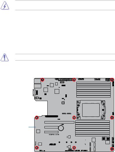
2.2.2Screw holes
Place nine (9) screws into the holes indicated by circles to secure the motherboard to the chassis.
DO NOT overtighten the screws! Doing so can damage the motherboard.
Place this side towards the rear of the chassis
|
|
|
|
|
|
|
|
|
|
|
|
|
|
|
|
|
|
|
|
|
|
|
|
|
|
|
|
|
|
|
|
|
|
|
|
|
|
|
|
|
|
|
|
|
|
|
|
|
|
|
|
|
|
|
|
|
|
|
|
|
|
|
|
|
|
|
|
|
|
|
|
|
|
|
|
|
|
|
|
|
|
|
|
|
|
|
|
|
|
|
|
|
|
|
|
|
|
|
|
|
|
|
|
|
|
|
|
|
|
|
|
|
|
|
|
|
|
|
|
|
|
|
|
|
|
|
|
|
|
|
|
|
|
|
|
|
|
|
|
|
|
|
|
|
|
|
|
|
|
|
|
|
|
|
|
|
|
|
|
KNPA-U16 |
2-3 |
||||||||||||||||||

2.2.3Motherboard layout
|
|
|
|
|
|
|
|
|
|
|
|
|
|
|
|
|
|
|
|
|
|
|
|
|
|
|
|
|
|
|
|
|
|
|
|
|
|
|
|
|
|
|
|
|
|
|
|
|
|
|
|
|
|
|
|
|
|
|
|
|
|
|
|
|
|
|
|
|
|
|
|
|
|
|
|
|
|
|
|
|
|
|
|
|
|
|
|
|
|
|
|
|
|
|
|
|
|
|
|
|
|
|
|
|
|
|
|
|
|
|
|
|
|
|
|
|
|
|
|
|
|
|
|
|
|
|
|
|
|
|
|
|
|
|
|
|
|
|
|
|
|
|
|
|
|
|
|
|
|
|
|
|
|
|
|
|
|
|
|
|
|
|
|
|
|
|
|
|
|
|
|
|
|
|
|
|
|
|
|
|
|
|
|
|
|
|
|
|
|
|
|
|
|
|
|
|
|
|
|
|
|
|
|
|
|
|
|
|
|
|
|
|
|
|
|
|
|
|
|
|
|
|
|
|
|
|
|
|
|
|
|
|
|
|
|
|
|
|
|
|
|
|
|
|
|
|
|
|
|
|
|
|
|
|
|
|
|
|
|
|
|
|
|
|
|
|
|
|
|
|
|
|
|
|
|
|
|
|
|
|
|
|
|
|
|
|
|
|
|
|
|
|
|
|
|
|
|
|
|
|
|
|
|
|
|
|
|
|
|
|
|
|
|
|
|
|
|
|
|
|
|
|
|
|
|
|
|
|
|
|
|
|
|
|
|
|
|
|
|
|
|
|
|
|
|
|
|
|
|
|
|
|
|
|
|
|
|
|
|
|
|
|
|
|
|
|
|
|
|
|
|
|
|
|
|
|
|
|
|
|
|
|
|
|
|
|
|
|
|
|
|
|
|
|
|
|
|
|
|
|
|
|
|
|
|
|
|
|
|
|
|
|
|
|
|
|
|
|
|
|
|
|
|
|
|
|
|
|
|
|
|
|
|
|
|
|
|
|
|
|
|
|
|
|
|
|
|
|
|
|
|
|
|
|
|
|
|
|
|
|
|
|
|
|
|
|
|
|
|
|
|
|
|
|
|
|
|
|
|
|
|
|
|
|
|
|
|
|
|
|
|
|
|
|
|
|
|
|
|
|
|
|
|
|
|
|
|
|
|
|
|
|
|
|
|
|
|
|
|
|
|
|
|
|
|
|
|
|
|
|
|
|
|
|
|
|
|
|
|
|
|
|
|
|
|
|
|
|
|
|
|
|
|
|
|
|
|
|
|
|
|
|
|
|
|
|
|
|
|
|
|
|
|
|
|
|
|
|
|
|
|
|
|
|
|
|
|
|
|
|
|
|
|
|
|
|
|
|
|
|
|
|
|
|
|
|
|
|
|
|
|
|
|
|
|
|
|
|
|
|
|
|
|
|
|
|
|
|
|
|
|
|
|
|
|
|
|
|
|
|
|
|
|
|
|
|
|
|
|
|
|
|
|
|
|
|
|
|
|
|
|
|
|
|
|
|
|
|
|
|
|
|
|
|
|
|
|
|
|
|
|
|
|
|
|
|
|
|
|
|
|
|
|
|
|
|
|
|
|
|
|
|
|
|
|
|
|
|
|
|
|
|
|
|
|
|
|
|
|
|
|
|
|
|
|
|
|
|
|
|
|
|
|
|
|
|
|
|
|
|
|
|
|
|
|
|
|
|
|
|
|
|
|
|
|
|
|
|
|
|
|
|
|
|
|
|
|
|
|
|
|
|
|
|
|
|
|
|
|
|
|
|
|
|
|
|
|
|
|
|
|
|
|
|
|
|
|
|
|
|
|
|
|
|
|
|
|
|
|
|
|
|
|
|
|
|
|
|
|
|
|
|
|
|
|
|
|
|
|
|
|
|
|
|
|
|
|
|
|
|
|
|
|
|
|
|
|
|
|
|
|
|
|
|
|
|
|
|
|
|
|
|
|
|
|
|
|
|
|
|
|
|
|
|
|
|
|
|
|
|
|
|
|
|
|
|
|
|
|
|
|
|
|
|
|
|
|
|
|
|
|
|
|
|
|
|
|
|
|
|
|
|
|
|
|
|
|
|
|
|
|
|
|
|
|
|
|
|
|
|
|
|
|
|
|
|
|
|
|
|
|
|
|
|
|
|
|
|
|
|
|
|
|
|
|
|
|
|
|
|
|
|
|
|
|
|
|
|
|
|
|
|
|
|
|
|
|
|
|
|
|
|
|
|
|
|
|
|
|
|
|
|
|
|
|
|
|
|
|
|
|
|
|
|
|
|
|
|
|
|
|
|
|
|
|
|
|
|
|
|
|
|
|
|
|
|
|
|
|
|
|
|
|
|
|
|
|
|
|
|
|
|
|
|
|
|
|
|
|
|
|
|
|
|
|
|
|
|
|
|
|
|
|
|
|
|
|
|
|
|
|
|
|
|
|
|
|
|
|
|
|
|
|
|
|
|
|
|
|
|
|
|
|
|
|
|
|
|
|
|
|
|
|
|
|
|
|
|
|
|
|
|
|
|
|
|
|
|
|
|
|
|
|
|
|
|
|
|
|
|
|
|
|
|
|
|
|
|
|
|
|
|
|
|
|
|
|
|
|
|
|
|
|
|
|
|
|
|
|
|
|
|
|
|
|
|
|
|
|
|
|
|
|
|
|
|
|
|
|
|
|
|
|
|
|
|
|
|
|
|
|
|
|
|
|
|
|
|
|
|
|
|
|
|
|
|
|
|
|
|
|
|
|
|
|
|
|
|
|
|
|
|
|
|
|
|
|
|
|
|
|
|
|
|
|
|
|
|
|
|
|
|
|
|
|
|
|
|
|
|
|
|
|
|
|
|
|
|
|
|
|
|
|
|
|
|
|
|
|
|
|
|
|
|
|
|
|
|
|
|
|
|
|
|
|
|
|
|
|
|
|
|
|
|
|
|
|
|
|
|
|
|
|
|
|
|
|
|
|
|
|
|
|
|
|
|
|
|
|
|
|
|
|
|
|
|
|
|
|
|
|
|
|
|
|
|
|
|
|
|
|
|
|
|
|
|
|
|
|
|
|
|
|
|
|
|
|
|
|
|
|
|
|
|
|
|
|
|
|
|
|
|
|
|
|
|
|
|
|
|
|
|
|
|
|
|
|
|
|
|
|
|
|
|
|
|
|
|
|
|
|
|
|
|
|
|
|
|
|
|
|
|
|
|
|
|
|
|
|
|
|
|
|
|
|
|
|
|
|
|
|
|
|
|
|
|
|
|
|
|
|
|
|
|
|
|
|
|
|
|
|
|
|
|
|
|
|
|
|
|
|
|
|
|
|
|
|
|
|
|
|
|
|
|
|
|
|
|
|
|
|
|
|
|
|
|
|
|
|
|
|
|
|
|
|
|
|
|
|
|
|
|
|
|
|
|
|
|
|
|
|
|
|
|
|
|
|
|
|
|
|
|
|
|
|
|
|
|
|
|
|
|
|
|
|
|
|
|
|
|
|
|
|
|
|
|
|
|
|
|
|
|
|
|
|
|
|
|
|
|
|
|
|
|
|
|
|
|
|
|
|
|
|
|
|
|
|
|
|
|
|
|
|
|
|
|
|
|
|
|
|
|
|
|
|
|
|
|
|
|
|
|
|
|
|
|
|
|
|
|
|
|
|
|
|
|
|
|
|
|
|
|
|
|
|
|
|
|
|
|
|
|
|
|
|
|
|
|
|
|
|
|
|
|
|
|
|
|
|
|
|
|
|
|
|
|
|
|
|
|
|
|
|
|
|
|
|
|
|
|
|
|
|
|
|
|
|
|
|
|
|
|
|
|
|
|
|
|
|
|
|
|
|
|
|
|
|
|
|
|
|
|
|
|
|
|
|
|
|
|
|
|
|
|
|
|
|
|
|
|
|
|
|
|
|
|
|
|
|
|
|
|
|
|
|
|
|
|
|
|
|
|
|
|
|
|
|
|
|
|
|
|
|
|
|
|
|
|
|
|
|
|
|
|
|
|
|
|
|
|
|
|
|
|
|
|
|
|
|
|
|
|
|
|
|
|
|
|
|
|
|
|
|
|
|
|
|
|
|
|
|
|
|
|
|
|
|
|
|
|
|
|
|
|
|
|
|
|
|
|
|
|
|
|
|
|
|
|
|
|
|
|
|
|
|
|
|
|
|
|
|
|
|
|
|
|
|
|
|
|
|
|
|
|
|
|
|
|
|
|
|
|
|
|
|
|
|
|
|
|
|
|
|
|
|
|
|
|
|
|
|
|
|
|
|
|
|
|
|
|
|
|
|
|
|
|
|
|
|
|
|
|
|
|
|
|
|
|
|
|
|
|
|
|
|
|
|
|
|
|
|
|
|
|
|
|
|
|
|
|
|
|
|
|
|
|
|
|
|
|
|
|
|
|
|
|
|
|
|
|
|
|
|
|
|
|
|
|
|
|
|
|
|
|
|
|
|
|
|
|
|
|
|
|
|
|
|
|
|
|
|
|
|
|
|
|
|
|
|
|
|
|
|
|
|
|
|
|
|
|
|
|
|
|
|
|
|
|
|
|
|
|
|
|
|
|
|
|
|
|
|
|
|
|
|
|
|
|
|
|
|
|
|
|
|
|
|
|
|
|
|
|
|
|
|
|
|
|
|
|
|
|
|
|
|
|
|
|
|
|
|
|
|
|
|
|
|
|
|
|
|
|
|
|
|
|
|
|
|
|
|
|
|
|
|
|
|
|
|
|
|
|
|
|
|
|
|
|
|
|
|
|
|
|
|
|
|
|
|
|
|
|
|
|
|
|
|
|
|
|
|
|
|
|
|
|
|
|
|
|
|
|
|
|
|
|
|
|
|
|
|
|
|
|
|
|
|
|
|
|
|
|
|
|
|
|
|
|
|
|
|
|
|
|
|
|
|
|
|
|
|
|
|
|
|
|
|
|
|
|
|
|
|
|
|
|
|
|
|
|
|
|
|
|
|
|
|
|
|
|
|
|
|
|
|
|
|
|
|
|
|
|
|
|
|
|
|
|
|
|
|
|
|
|
|
|
|
|
|
|
|
|
|
|
|
|
|
|
|
|
|
|
|
|
|
|
|
|
|
|
|
|
|
|
|
|
|
|
|
|
|
|
|
|
|
|
|
|
|
|
|
|
|
|
|
|
|
|
2-4 |
|
|
|
|
|
|
|
|
|
|
|
|
|
|
|
|
|
|
|
|
|
|
|
|
|
|
|
|
|
|
|
|
|
|
Chapter 2: Hardware Information |
|||||||||||||||||

Layout contents
Internal connectors / Sockets / Jumpers / LEDs |
Page |
|
1. |
LAN controller settings (3-pin LAN_SW1-2) |
2-16 |
2. |
LANNCSI setting (3-pin LANNCSI_SEL1) |
2-18 |
3. |
Micro SD card slot (MSD1) |
2-32 |
4. |
Smart Ride Through (SmaRT) setting (3-pin SMART_PSU1) |
2-18 |
5. |
Power Supply SMBus connector (5-pin PSUSMB1) |
2-23 |
6. |
ATX power connectors (24-pin EATXPWR1, 8-pin EATX12V1) |
2-26 |
7. |
CPU, front, and rear fan connectors (4-pin FRNT_FAN1-7, |
2-25 |
|
REAR_FAN1-2) |
|
|
|
|
8. |
USB 3.0 connector (20-1 pin USB3_34; 4-pin Type-A USB3_4) |
2-24 |
9. |
DDR4 DIMM sockets |
2-10 |
10. |
CPU socket |
2-6 |
11. |
Serial ATA connectors (7-pin SATA1-4) |
2-23 |
12. |
Mini-SAS HD connectors (ISATA1-2) |
2-33 |
13. |
OCUPCIE connectors (MPCIE_HD1-6) |
2-30 |
14. |
M.2 (NGFF) connectors (NGFF1) |
2-31 |
15. |
System panel connector (20-1 pin PANEL1) |
2-27 |
16. |
Auxiliary panel connector (20-2 pin AUX_PANEL1, 20-pin |
2-28 |
|
AUX_PANEL2) |
|
|
|
|
17. |
Hard disk activity LED connector (4-pin HDLED1) |
2-29 |
18. |
LAN Activity LED connector (5-1 pin LAN34_LED1) |
2-25 |
19. |
Chassis Intrusion connectors (2-pin INTRUSION) |
2-30 |
20. |
Serial port connector (10-1 pin COM1) |
2-24 |
21. |
Q-Code LEDs |
2-21 |
22. |
Clear RTC RAM (3-pin CLRTC1) |
2-15 |
23. |
Mezzanine PCIE card connectors (MEZZPCIE1) |
2-31 |
24. |
VGA controller setting (3-pin VGA_SW1) |
2-16 |
25. |
BMC Setting (3-pin BMC_EN1) |
2-17 |
26. |
VGA connector (10-1 pin VGA_HDR1) |
2-29 |
27. |
Trusted Platform Module connector (20-1 pin TPM1) |
2-26 |
28. |
VPP_I2C1 connector (10-1 pin VPP_I2C1) |
2-33 |
29. |
DMLAN setting (3-pin DM_IP_EN1) |
2-17 |
30. |
OCP LAN Activity LED connector (4-1 pin OCP_LED1) |
2-32 |
KNPA-U16 |
2-5 |
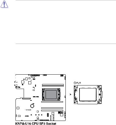
2.3Central Processing Unit (CPU)
The motherboard comes with a surface mount Socket SP3 designed for the AMD EPYC™ 7000 Series.
•Upon purchase of the motherboard, ensure that the PnP cap is on the socket and
the socket contacts are not bent. Contact your retailer immediately if the PnP cap is missing, or if you see any damage to the PnP cap/socket contacts/motherboard components. ASUS will shoulder the cost of repair only if the damage is shipment/ transit-related.
•Keep the cap after installing the motherboard. ASUS will process Return Merchandise
Authorization (RMA) requests only if the motherboard comes with the cap on the Socket SP3.
•The product warranty does not cover damage to the socket contacts resulting from incorrect CPU installation/removal, or misplacement/loss/incorrect removal of the PnP cap.
2.3.1Installing the CPU
To install the CPU:
1.Locate the CPU socket on the motherboard.
|
|
|
|
|
|
|
|
|
|
|
|
|
|
|
|
|
|
|
|
|
|
|
|
|
|
|
|
|
|
|
|
|
|
|
|
|
|
|
|
|
|
|
|
|
|
|
|
|
|
|
|
|
|
|
|
|
|
|
|
|
|
|
|
|
|
|
|
|
|
|
|
|
|
|
|
|
|
|
|
|
|
|
|
|
|
|
|
|
|
|
|
|
|
|
|
|
|
|
|
|
|
|
|
|
|
|
|
|
|
|
|
|
|
|
|
|
|
|
|
|
|
|
|
|
|
|
|
|
|
|
|
|
|
|
|
|
|
|
|
|
|
|
|
|
|
|
|
|
|
|
|
|
|
|
|
|
|
|
|
|
|
|
|
|
|
|
|
|
|
|
|
|
|
|
|
|
|
|
|
|
|
|
|
|
|
|
|
|
|
|
|
|
|
|
|
|
|
|
|
|
|
|
|
|
|
|
|
|
|
|
|
|
|
|
|
|
|
|
|
|
|
|
|
|
|
|
|
|
|
|
|
|
|
|
|
|
|
|
|
|
|
|
|
|
|
|
|
|
|
|
|
|
|
|
|
|
|
|
|
|
|
|
|
|
|
|
|
|
|
|
|
|
|
|
|
|
|
|
|
|
|
|
|
|
|
|
|
|
|
|
|
|
|
|
|
|
|
|
|
|
|
|
|
|
|
|
|
|
|
|
|
|
|
|
|
|
|
|
|
|
|
|
|
|
|
|
|
|
|
|
|
|
|
|
|
|
|
|
|
|
|
|
|
|
|
|
|
|
|
|
|
|
|
|
|
|
|
|
|
|
|
|
|
|
|
|
|
|
|
|
|
|
|
|
|
|
|
|
|
|
|
|
|
|
|
|
|
|
|
|
|
|
|
|
|
|
|
|
|
|
|
|
|
|
|
|
|
|
|
|
|
|
|
|
|
|
|
|
|
|
|
|
|
|
|
|
|
|
|
|
|
|
|
|
|
|
|
|
|
|
|
|
|
|
|
|
|
|
|
|
|
|
|
|
|
|
|
|
|
|
|
|
|
|
|
|
|
|
|
|
|
|
|
|
|
|
|
|
|
|
|
|
|
|
|
|
|
|
|
|
|
|
|
|
|
|
|
|
|
|
|
|
|
|
|
|
|
|
|
|
|
|
|
|
|
|
|
|
|
|
|
|
|
|
|
|
|
|
|
|
|
|
|
|
|
|
|
|
|
|
|
|
|
|
|
|
|
|
|
|
|
|
|
|
|
|
|
|
|
|
|
|
|
|
|
|
|
|
|
|
|
|
|
|
|
|
|
|
|
|
|
|
|
|
|
|
|
|
|
|
|
|
|
|
|
|
|
|
|
|
|
|
|
|
|
|
|
|
|
|
|
|
|
|
|
|
|
|
|
|
|
|
|
|
|
|
|
|
|
|
|
|
|
|
|
|
|
|
|
|
|
|
|
|
|
|
|
|
|
|
|
|
|
|
|
|
|
|
|
|
|
|
|
|
|
|
|
|
|
|
|
|
|
|
|
|
|
|
|
|
|
|
|
|
|
|
|
|
|
|
|
|
|
|
|
|
|
|
|
|
|
|
|
|
|
|
|
|
|
|
|
|
|
2-6 |
|
|
|
|
|
|
|
|
|
|
|
|
|
|
|
|
|
|
|
|
|
|
|
|
|
|
|
|
|
|
|
|
|
|
|
|
|
|
|
|
|
|
|
|
|
Chapter 2: Hardware Information |
||||
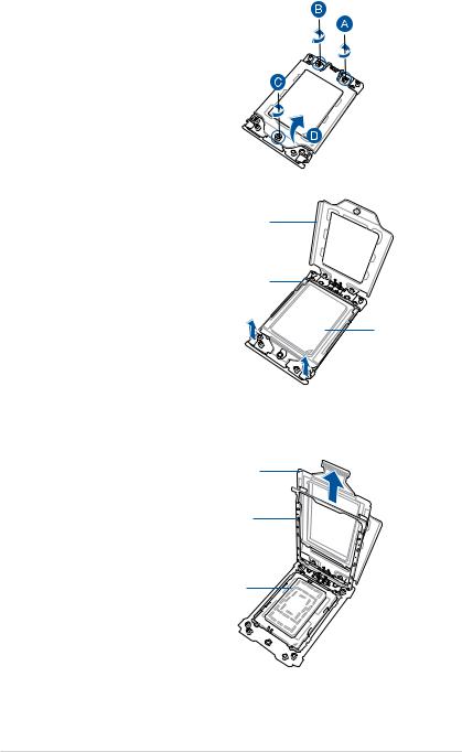
2.Loosen each screw one by one in the
sequence shown on the socket to open the load plate.
3.Slightly lift open the rail frame.
Load plate
Rail frame |
External cap
4.Slide the external cap out of the rail frame.
External cap
Rail frame
PnP cap
KNPA-U16 |
2-7 |
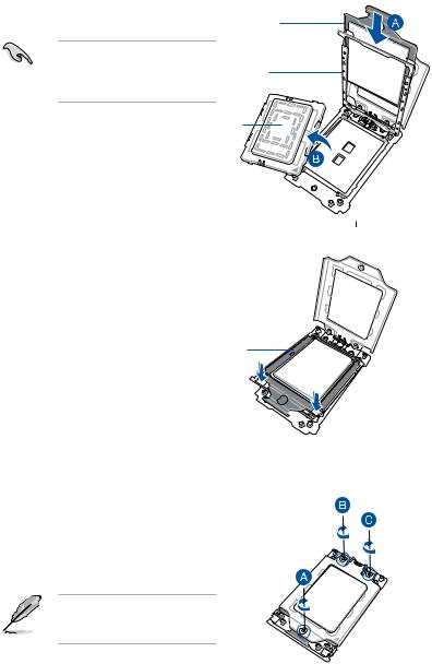
5.Slide the carrier frame with CPU into the rail frame, then remove the PnP cap.
The carrier frame with CPU fits in only one correct orientation. DO NOT force the carrier frame with CPU into the rail frame.
Carrier frame with CPU
Rail frame
PnP cap
6.Gently push the rail frame just enough
to let it sit on top of the CPU socket.
Carrier frame with CPU
7. Close the load plate just enough to let it sit on top of the CPU, then secure each screw one by one in the sequence shown on the socket to completely secure the load plate.
The load plate screws are T20 models. A torque value of 12 inch-lbf is recommended.
2-8 |
Chapter 2: Hardware Information |
8.Twist each of the four screws with a screwdriver just enough to attach the heatsink to the motherboard. When the four screws are attached, tighten them one by one in a diagonal sequence to complete the installation.
The heatsink screws are T20 models. A torque value of 12 inch-lbf is recommended.
KNPA-U16 |
2-9 |
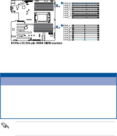
2.4System memory
2.4.1Overview
The motherboard comes with sixteen (16) Double Data Rate 4 (DDR4) Dual Inline Memory Modules (DIMM) sockets.
The figure illustrates the location of the DDR4 DIMM sockets:
2.4.2Memory Configurations
You may install 32GB, 16GB, 8GB, 4GB RDIMM, 64GB, 32GB LRDIMM, or 128GB, 64GB LRDIMM 3DS into the DIMM sockets using the memory configurations in this section.
Memory configurations
|
|
|
|
|
|
|
|
DIMM |
|
|
|
|
|
|
|
|
|
A1 |
A2 |
B1 |
B2 |
C1 |
C2 |
D1 |
D2 |
E1 |
E2 |
F1 |
F2 |
G1 |
G2 |
H1 |
H2 |
1 DIMM |
|
P |
|
|
|
|
|
|
|
|
|
|
|
|
|
|
2 DIMMs |
|
P |
|
|
|
|
|
|
|
P |
|
|
|
|
|
|
4 DIMMs |
|
P |
|
P |
|
|
|
|
|
P |
|
P |
|
|
|
|
6 DIMMs |
|
P |
|
P |
|
P |
|
|
|
P |
|
P |
|
P |
|
|
8 DIMMs |
|
P |
|
P |
|
P |
|
P |
|
P |
|
P |
|
P |
|
P |
10 DIMMs |
P |
P |
|
P |
|
P |
|
P |
P |
P |
|
P |
|
P |
|
P |
12 DIMMs |
P |
P |
P |
P |
|
P |
|
P |
P |
P |
P |
P |
|
P |
|
P |
14 DIMMs |
P |
P |
P |
P |
P |
P |
|
P |
P |
P |
P |
P |
P |
P |
|
P |
16 DIMMs |
P |
P |
P |
P |
P |
P |
P |
P |
P |
P |
P |
P |
P |
P |
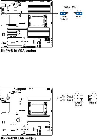
P |
P |
•Always install DIMMs with the same CAS latency. For optimum compatibility, it is
recommended that you obtain memory modules from the same vendor.
•Start installing the DIMMs in slots A2.
2-10 |
Chapter 2: Hardware Information |
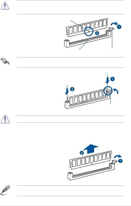
2.4.3Installing a DIMM on a single clip DIMM socket
Ensure to unplug the power supply before adding or removing DIMMs or other system components. Failure to do so may cause severe damage to both the motherboard and the components.
1. |
Unlock a DIMM socket by pressing the DIMM notch |
|
|
retaining clip outward. |
|
2. |
Align a DIMM on the socket such that |
|
|
the notch on the DIMM matches the |
|
|
DIMM slot key on the socket. |
|
|
DIMM slot key |
Unlocked retaining clip |
|
|
|
|
A DIMM is keyed with a notch so that it fits in only one direction. DO NOT force a DIMM into |
|
|
a socket in the wrong direction to avoid damaging the DIMM. |
|
3. |
Hold the DIMM by both of its ends |
|
|
then insert the DIMM vertically into the |
|
|
socket. Apply force to both ends of the |
|
|
DIMM simultaneously until the retaining |
|
|
clip snaps back into place and the |
|
|
DIMM cannot be pushed in any further |
|
|
to ensure proper sitting of the DIMM. |
|
|
|
Locked Retaining Clip |
Always insert the DIMM into the socket vertically to prevent DIMM notch damage.
Removing a DIMM from a single clip DIMM socket
1.Press the retaining clip outward to unlock the DIMM.
2. Remove the DIMM from the socket.
Support the DIMM lightly with your fingers when pressing the retaining clips. The DIMM might get damaged when it flips out with extra force.
KNPA-U16 |
2-11 |

2.5Expansion slots
In the future, you may need to install expansion cards. The following subsections describe the slots and the expansion cards that they support.
Ensure to unplug the power cord before adding or removing expansion cards. Failure to do so may cause you physical injury and damage motherboard components.
2.5.1Installing an expansion card
To install an expansion card:
1.Before installing the expansion card, read the documentation that came with it and make the necessary hardware settings for the card.
2.Remove the system unit cover (if your motherboard is already installed in a chassis).
3.Remove the bracket opposite the slot that you intend to use. Keep the screw for later use.
4.Align the card connector with the slot and press firmly until the card is completely seated on the slot.
5.Secure the card to the chassis with the screw you removed earlier.
6.Replace the system cover.
2.5.2Configuring an expansion card
After installing the expansion card, configure it by adjusting the software settings.
1.Turn on the system and change the necessary BIOS settings, if any. See Chapter 4 for information on BIOS setup.
2.Assign an IRQ to the card. Refer to the tables on the next page.
3.Install the software drivers for the expansion card.
When using PCI cards on shared slots, ensure that the drivers support “Share IRQ” or that the cards do not need IRQ assignments. Otherwise, conflicts will arise between the two PCI groups, making the system unstable and the card inoperable.
2-12 |
Chapter 2: Hardware Information |

2.5.3Interrupt assignments
Standard Interrupt assignments
IRQ |
Priority |
Standard function |
|
|
|
0 |
1 |
System Timer |
1 |
2 |
Keyboard Controller |
2 |
- |
Programmable Interrupt |
3* |
|
|
4* |
12 |
Communications Port (COM1) |
5* |
13 |
-- |
6 |
|
|
7* |
15 |
-- |
8 |
3 |
System CMOS/Real Time Clock |
9* |
4 |
ACPI Mode when used |
10* |
5 |
IRQ Holder for PCI Steering |
11* |
6 |
IRQ Holder for PCI Steering |
12* |
7 |
PS/2 Compatible Mouse Port |
13 |
8 |
Numeric Data Processor |
14* |
|
|
15* |
|
|
* These IRQs are usually available for ISA or PCI devices.
KNPA-U16 |
2-13 |
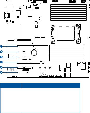
No.(Slot location) Short Description
PCIE6 |
PCI-E x24 |
(x16 |
Gen3 link) |
PCIE5 |
PCI-E x8 (x4 Gen3 link) |
||
PCIE4 |
PCI-E x8 (x4 Gen3 link) |
||
PCIE3 |
PCI-E x16 |
(x16 |
Gen3 link)* |
PCIE2 |
PCI-E x8 (x4 Gen3 link) |
||
PCIE1 |
PCI-E x16 |
(x16 |
Gen3 link) |
* When Slot Location 2 is occupied, Slot Location 3 will switch to PCIe 3.0 x8 link.
2-14 |
Chapter 2: Hardware Information |
2.6Jumpers
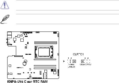
1.Clear RTC RAM (3-pin CLRTC1)
This jumper allows you to clear the Real Time Clock (RTC) RAM in CMOS. You can clear the CMOS memory of date, time, and system setup parameters by erasing the CMOS RTC RAM data. The onboard button cell battery powers the RAM data in CMOS which include system setup information such as system passwords.
To erase the RTC RAM:
1.Turn OFF the computer and unplug the power cord.
2.Move the jumper cap from the default pins 1–2 to pins 2–3. Keep the cap on pins 2–3 for about 5 to 10 seconds, then move the cap back to pins 1–2.
3.Plug the power cord and turn ON the computer.
4.Hold down the <Del> key during the boot process and enter BIOS setup to reenter data.
DO NOT remove the cap on CLRTC jumper default position except when clearing the RTC
RAM. Removing the cap will cause system boot failure!
If the steps above do not help, remove the onboard battery and move the jumper again to clear the CMOS RTC RAM data. After the CMOS clearance, reinstall the battery.
|
|
|
|
|
|
|
|
|
|
|
|
|
|
|
|
|
|
|
|
|
|
|
|
|
|
|
|
|
|
|
|
|
|
|
|
|
|
|
|
|
|
|
|
|
|
|
|
|
|
|
|
|
|
|
|
|
|
|
|
|
|
|
|
|
|
|
|
|
|
|
|
|
|
|
|
|
|
|
|
|
|
|
|
|
|
|
|
|
|
|
|
|
|
|
|
|
|
|
|
|
|
|
|
|
|
|
|
|
|
|
|
|
|
|
|
|
|
|
|
|
|
|
|
|
|
|
|
|
|
|
|
|
|
|
|
|
|
|
|
|
|
|
|
|
|
|
|
|
|
|
|
|
|
|
|
|
|
|
|
|
|
|
|
|
|
|
|
|
|
|
|
|
|
|
|
|
|
|
|
|
|
|
|
|
|
|
|
|
|
|
|
|
|
|
|
|
|
|
|
|
|
|
|
|
|
|
|
|
|
|
|
|
|
|
|
|
|
|
|
|
|
|
|
|
|
|
|
|
|
|
|
|
|
|
|
|
|
|
|
|
|
|
|
|
|
|
|
|
|
|
|
|
|
|
|
|
|
|
|
|
|
|
|
|
|
|
|
|
|
|
|
|
|
|
|
|
|
|
|
|
|
|
|
|
|
|
|
|
|
|
|
|
|
|
|
|
|
|
|
|
|
|
|
|
|
|
|
|
|
|
|
|
|
|
|
|
|
|
|
|
|
|
|
|
|
|
|
|
|
|
|
|
|
|
|
|
|
|
|
|
|
|
|
|
|
|
|
|
|
|
|
|
|
|
|
|
|
|
|
|
|
|
|
|
|
|
|
|
|
|
|
|
|
|
|
|
|
|
|
|
|
|
|
|
|
|
|
|
|
|
|
|
|
|
|
|
|
|
|
|
|
|
|
|
|
|
|
|
|
|
|
|
|
|
|
|
|
|
|
|
|
|
|
|
|
|
|
|
|
|
|
|
|
|
|
|
|
|
|
|
|
|
|
|
|
|
|
|
|
|
|
|
|
|
|
|
|
|
|
|
|
|
|
|
|
|
|
|
|
|
|
|
|
|
|
|
|
|
|
|
|
|
|
|
|
|
|
|
|
|
|
|
|
|
|
|
|
|
|
|
|
|
|
|
|
|
|
|
|
|
|
|
|
|
|
|
|
|
|
|
|
|
|
|
|
|
|
|
|
|
|
|
|
|
|
|
|
|
|
|
|
|
|
|
|
|
|
|
|
|
|
|
|
|
|
|
|
|
|
|
|
|
|
|
|
|
|
|
|
|
|
|
|
|
|
|
|
|
|
|
|
|
|
|
|
|
|
|
|
|
|
|
|
|
|
|
|
|
|
|
|
|
|
|
|
|
|
|
|
|
|
|
|
|
|
|
|
|
|
|
|
|
|
|
|
|
|
|
|
|
|
|
|
|
|
|
|
|
|
|
|
|
|
|
|
|
|
|
|
|
|
|
|
|
|
|
|
|
|
|
|
|
|
|
|
|
|
|
|
|
|
|
|
|
|
|
|
|
|
|
|
|
|
|
|
|
|
|
|
|
|
|
|
|
|
|
|
|
|
|
|
|
|
|
|
|
|
|
|
|
|
|
|
|
|
|
|
|
|
|
|
|
|
|
|
|
|
|
|
|
|
|
|
|
|
|
|
|
|
|
|
|
|
|
|
|
|
|
|
|
|
|
|
|
|
|
|
|
|
|
|
|
|
|
|
|
|
|
|
|
|
|
|
|
|
|
|
|
|
|
|
|
|
|
|
|
|
|
|
|
|
|
|
|
|
|
|
|
|
|
|
|
|
|
|
|
|
|
|
|
|
|
|
|
|
KNPA-U16 |
2-15 |
||||||||||||||||||||||||||||||||||||||||||||||
2.VGA controller setting (3-pin VGA_SW1)
This jumper allows you to enable or disable the onboard VGA controller. Set to pins 1–2 to activate the VGA feature.
3.LAN controller settings (3-pin LAN_SW1-2)
These jumpers allow you to enable or disable the onboard LAN_SW1 or LAN_SW2.
Set to pins 1-2 to activate the Gigabit LAN feature.
|
|
|
|
|
|
|
|
|
|
|
|
|
|
|
|
|
|
|
|
|
|
|
|
|
|
|
|
|
|
|
|
|
|
|
|
|
|
|
|
|
|
|
|
|
|
|
|
|
|
|
|
|
|
|
|
|
|
|
|
|
|
|
|
|
|
|
|
|
|
|
|
|
|
|
|
|
|
|
|
|
|
|
|
|
|
|
|
|
|
|
|
|
|
|
|
|
|
|
|
|
|
|
|
|
|
|
|
|
|
|
|
|
|
|
|
|
|
|
|
|
|
|
|
|
|
|
|
|
|
|
|
|
|
|
|
|
|
|
|
|
|
|
|
|
|
|
|
|
|
|
|
|
|
|
|
|
|
|
|
|
|
|
|
|
|
|
|
|
|
|
|
|
|
|
|
|
|
|
|
|
|
|
|
|
|
|
|
|
|
|
|
|
|
|
|
|
|
|
|
|
|
|
|
|
|
|
|
|
|
|
|
|
|
|
|
|
|
|
|
|
|
|
|
|
|
|
|
|
|
|
|
|
|
|
|
|
|
|
|
|
|
|
|
|
|
|
|
|
|
|
|
|
|
|
|
|
|
|
|
|
|
|
|
|
|
|
|
|
|
|
|
|
|
|
|
|
|
|
|
|
|
|
|
|
|
|
|
|
|
|
|
|
|
|
|
|
|
|
|
|
|
|
|
|
|
|
|
|
|
|
|
|
|
|
|
|
|
|
|
|
|
|
|
|
|
|
|
|
|
|
|
|
|
|
|
|
|
|
|
|
|
|
|
|
|
|
|
|
|
|
|
|
|
|
|
|
|
|
|
|
|
|
|
|
|
|
|
|
|
|
|
|
|
|
|
|
|
|
|
|
|
|
|
|
|
|
|
|
|
|
|
|
|
|
|
|
|
|
|
|
|
|
|
|
|
|
|
|
|
|
|
|
|
|
|
|
|
|
|
|
|
|
|
|
|
|
|
|
|
|
|
|
|
|
|
|
|
|
|
|
|
|
|
|
|
|
|
|
|
|
|
|
|
|
|
|
|
|
|
|
|
|
|
|
|
|
|
|
|
|
|
|
|
|
|
|
|
|
|
|
|
|
|
|
|
|
|
|
|
|
|
|
|
|
|
|
|
|
|
|
|
|
|
|
|
|
|
|
|
|
|
|
|
|
|
|
|
|
|
|
|
|
|
|
|
|
|
|
|
|
|
|
|
|
|
|
|
|
|
|
|
|
|
|
|
|
|
|
|
|
|
|
|
|
|
|
|
|
|
|
|
|
|
|
|
|
|
|
|
|
|
|
|
|
|
2-16 |
|
|
|
|
|
|
|
|
|
|
|
|
|
|
|
|
|
|
|
|
|
|
|
|
|
|
|
|
|
|
|
|
|
|
|
|
|
|
|
|
|
|
Chapter 2: Hardware Information |
||||

4.BMC Setting (3-pin BMC_EN1)
This jumper allows you to enable or disable the Baseboard Management Controller (ASMB9).
5.DMLAN setting (3-pin DM_IP_EN1)
This jumper allows you to select the DMLAN setting. Set to pins 2-3 to force the
DMLAN IP to static mode (IP=10.10.10.10, submask=255.255.255.0).
|
|
|
|
|
|
|
|
|
|
|
|
|
|
|
|
|
|
|
|
|
|
|
|
|
|
|
|
|
|
|
|
|
|
|
|
|
|
|
|
|
|
|
|
|
|
|
|
|
|
|
|
|
|
|
|
|
|
|
|
|
|
|
|
|
|
|
|
|
|
|
|
|
|
|
|
|
|
|
|
|
|
|
|
|
|
|
|
|
|
|
|
|
|
|
|
|
|
|
|
|
|
|
|
|
|
|
|
|
|
|
|
|
|
|
|
|
|
|
|
|
|
|
|
|
|
|
|
|
|
|
|
|
|
|
|
|
|
|
|
|
|
|
|
|
|
|
|
|
|
|
|
|
|
|
|
|
|
|
|
|
|
|
|
|
|
|
|
|
|
|
|
|
|
|
|
|
|
|
|
|
|
|
|
|
|
|
|
|
|
|
|
|
|
|
|
|
|
|
|
|
|
|
|
|
|
|
|
|
|
|
|
|
|
|
|
|
|
|
|
|
|
|
|
|
|
|
|
|
|
|
|
|
|
|
|
|
|
|
|
|
|
|
|
|
|
|
|
|
|
|
|
|
|
|
|
|
|
|
|
|
|
|
|
|
|
|
|
|
|
|
|
|
|
|
|
|
|
|
|
|
|
|
|
|
|
|
|
|
|
|
|
|
|
|
|
|
|
|
|
|
|
|
|
|
|
|
|
|
|
|
|
|
|
|
|
|
|
|
|
|
|
|
|
|
|
|
|
|
|
|
|
|
|
|
|
|
|
|
|
|
|
|
|
|
|
|
|
|
|
|
|
|
|
|
|
|
|
|
|
|
|
|
|
|
|
|
|
|
|
|
|
|
|
|
|
|
|
|
|
|
|
|
|
|
|
|
|
|
|
|
|
|
|
|
|
|
|
|
|
|
|
|
|
|
|
|
|
|
|
|
|
|
|
|
|
|
|
|
|
|
|
|
|
|
|
|
|
|
|
|
|
|
|
|
|
|
|
|
|
|
|
|
|
|
|
|
|
|
|
|
|
|
|
|
|
|
|
|
|
|
|
|
|
|
|
|
|
|
|
|
|
|
|
|
|
|
|
|
|
|
|
|
|
|
|
|
|
|
|
|
|
|
|
|
|
|
|
|
|
|
|
|
|
|
|
|
|
|
|
|
|
|
|
|
|
|
|
|
|
|
|
|
|
|
|
|
|
|
|
|
|
|
|
|
|
|
|
|
|
|
|
|
|
|
|
|
|
|
|
|
|
|
|
|
|
|
|
|
|
|
|
|
|
|
|
|
|
|
|
|
|
|
|
|
|
|
|
|
|
|
|
|
|
|
|
|
|
|
|
|
|
|
|
|
|
|
|
|
|
|
|
|
|
|
|
|
|
|
|
|
|
|
|
|
|
|
|
|
|
|
|
|
|
|
|
|
|
|
|
|
|
|
|
|
|
|
|
|
|
|
|
|
|
|
|
|
|
|
|
|
|
|
|
|
|
|
|
|
|
|
|
|
|
|
|
|
|
|
|
|
|
|
|
|
|
|
|
|
|
|
|
|
|
|
|
|
|
|
|
|
|
|
|
|
|
|
|
|
|
|
|
|
|
|
|
|
|
|
|
|
|
|
|
|
|
|
|
|
|
|
|
|
|
|
|
|
|
|
|
|
|
|
|
|
|
|
|
|
|
|
|
|
|
|
|
|
|
|
|
|
|
|
|
|
|
|
|
|
|
|
|
|
|
|
|
|
|
|
|
|
|
|
|
|
|
|
|
|
|
|
|
KNPA-U16 |
2-17 |
||||||||||||||||||||||||||||||||||||||||||||
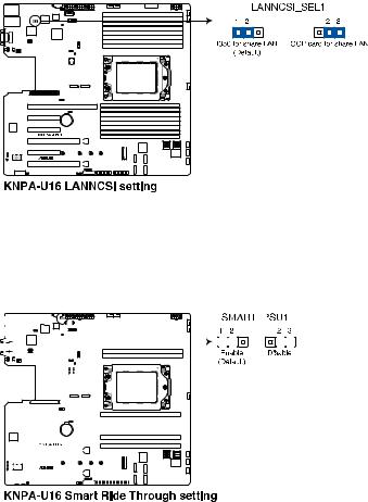
6.LANNCSI setting (3-pin LANNCSI_SEL1)
This jumper allows you to select which LAN NCSI to function.
7.Smart Ride Through (SmaRT) setting (3-pin SMART_PSU1)
This jumper allows you to enable or disable the Smart Ride Through (SmaRT) function.
This feature is enabled by default. Set to pins 2-3 to disable it. When enabled, SmaRT allows uninterrupted operation of the system during an AC loss event.
|
|
|
|
|
|
|
|
|
|
|
|
|
|
|
|
|
|
|
|
|
|
|
|
|
|
|
|
|
|
|
|
|
|
|
|
|
|
|
|
|
|
|
|
|
|
|
|
|
|
|
|
|
|
|
|
|
|
|
|
|
|
|
|
|
|
|
|
|
|
|
|
|
|
|
|
|
|
|
|
|
|
|
|
|
|
|
|
|
|
|
|
|
|
|
|
|
|
|
|
|
|
|
|
|
|
|
|
|
|
|
|
|
|
|
|
|
|
|
|
|
|
|
|
|
|
|
|
|
|
|
|
|
|
|
|
|
|
|
|
|
|
|
|
|
|
|
|
|
|
|
|
|
|
|
|
|
|
|
|
|
|
|
|
|
|
|
|
|
|
|
|
|
|
|
|
|
|
|
|
|
|
|
|
|
|
|
|
|
|
|
|
|
|
|
|
|
|
|
|
|
|
|
|
|
|
|
|
|
|
|
|
|
|
|
|
|
|
|
|
|
|
|
|
|
|
|
|
|
|
|
|
|
|
|
|
|
|
|
|
|
|
|
|
|
|
|
|
|
|
|
|
|
|
|
|
|
|
|
|
|
|
|
|
|
|
|
|
|
|
|
|
|
|
|
|
|
|
|
|
|
|
|
|
|
|
|
|
|
|
|
|
|
|
|
|
|
|
|
|
|
|
|
|
|
|
|
|
|
|
|
|
|
|
|
|
|
|
|
|
|
|
|
|
|
|
|
|
|
|
|
|
|
|
|
|
|
|
|
|
|
|
|
|
|
|
|
|
|
|
|
|
|
|
|
|
|
|
|
|
|
|
|
|
|
|
|
|
|
|
|
|
|
|
|
|
|
|
|
|
|
|
|
|
|
|
|
|
|
|
|
|
|
|
|
|
|
|
|
|
|
|
|
|
|
|
|
|
|
|
|
|
|
|
|
|
|
|
|
|
|
|
|
|
|
|
|
|
|
|
|
|
|
|
|
|
|
|
|
|
|
|
|
|
|
|
|
|
|
|
|
|
|
|
|
|
|
|
|
|
|
|
|
|
|
|
|
|
|
|
|
|
|
|
|
|
|
|
|
|
|
|
|
|
|
|
|
|
|
|
|
|
|
|
|
|
|
|
|
|
|
|
|
|
|
|
|
|
|
|
|
|
|
|
|
|
|
|
|
|
|
|
|
|
|
|
|
|
|
|
|
|
|
|
|
|
|
|
|
|
|
|
|
|
|
|
|
|
|
|
|
|
|
|
|
|
|
|
|
|
|
|
|
|
|
|
|
|
|
|
|
|
|
|
|
|
|
|
|
|
|
|
|
|
|
|
|
|
|
|
|
|
|
|
|
|
|
|
|
|
|
|
|
|
|
|
|
|
|
|
|
|
|
|
|
|
|
|
|
|
|
|
|
|
|
|
|
|
|
|
|
|
|
|
|
|
|
|
|
|
|
|
|
|
|
|
|
|
|
|
|
|
|
|
|
|
|
|
|
|
|
|
|
|
|
|
|
|
|
|
|
|
|
|
|
|
|
|
|
|
|
|
|
|
|
|
|
|
|
|
|
|
|
|
|
|
|
|
|
|
|
|
|
|
|
|
|
|
|
|
|
|
|
|
|
|
|
|
|
|
|
|
|
|
|
|
|
|
|
|
|
|
|
|
|
|
|
|
|
|
|
|
2-18 |
|
|
|
|
|
|
|
|
|
|
|
|
|
|
|
|
|
|
|
|
|
|
|
|
|
|
|
|
|
|
|
|
|
|
|
|
|
|
|
|
|
|
|
|
|
|
|
Chapter 2: Hardware Information |
||||
 Loading...