


M2N8-VMX
Motherboard

E2813
First Edition V1
September 2006
Copyright © 2006 ASUSTeK COMPUTER INC. All Rights Reserved.
No part of this manual, including the products and software described in it, may be reproduced, transmitted, transcribed, stored in a retrieval system, or translated into any language in any form or by any means, except documentation kept by the purchaser for backup purposes, without the express written permission of ASUSTeK COMPUTER INC. (“ASUS”).
Product warranty or service will not be extended if: (1) the product is repaired, modified or altered, unless such repair, modification of alteration is authorized in writing by ASUS; or (2) the serial number of the product is defaced or missing.
ASUS PROVIDES THIS MANUAL “AS IS” WITHOUT WARRANTY OF ANY KIND, EITHER EXPRESS OR IMPLIED, INCLUDING BUT NOT LIMITED TO THE IMPLIED WARRANTIES OR CONDITIONS OF MERCHANTABILITY OR FITNESS FOR A PARTICULAR PURPOSE. IN NO EVENT SHALL ASUS, ITS DIRECTORS, OFFICERS, EMPLOYEES OR AGENTS BE LIABLE FOR ANY INDIRECT, SPECIAL,
INCIDENTAL, OR CONSEQUENTIAL DAMAGES (INCLUDING DAMAGES FOR LOSS OF PROFITS, LOSS OF BUSINESS, LOSS OF USE OR DATA, INTERRUPTION OF BUSINESS AND THE LIKE), EVEN IF ASUS HAS BEEN ADVISED OF THE POSSIBILITY OF SUCH DAMAGES ARISING FROM ANY DEFECT OR ERROR IN THIS MANUAL OR PRODUCT.
SPECIFICATIONS AND INFORMATION CONTAINED IN THIS MANUAL ARE FURNISHED FOR INFORMATIONAL USE ONLY, AND ARE SUBJECT TO CHANGE AT ANY TIME WITHOUT NOTICE, AND SHOULD NOT BE CONSTRUED AS A COMMITMENT BY ASUS. ASUS ASSUMES NO RESPONSIBILITY OR LIABILITY FOR ANY ERRORS OR INACCURACIES THAT MAY APPEAR IN THIS MANUAL, INCLUDING THE PRODUCTS AND SOFTWARE DESCRIBED IN IT.
Products and corporate names appearing in this manual may or may not be registered trademarks or copyrights of their respective companies, and are used only for identification or explanation and to the owners’ benefit, without intent to infringe.
ii

Contents
Notices................................................................................................. |
vi |
Safety information............................................................................... |
vii |
M2N8-VMX specifications summary...................................................... |
x |
Chapter 1: Product introduction
1.1 |
Welcome!............................................................................... |
1-2 |
|
1.2 |
Package contents.................................................................. |
1-2 |
|
1.3 |
Special features..................................................................... |
1-2 |
|
|
1.3.1 |
Product highlights .................................................... |
1-2 |
|
1.3.2 |
Innovative ASUS features ....................................... |
1-5 |
1.4 |
Before you proceed............................................................... |
1-6 |
|
1.5 |
Motherboard overview........................................................... |
1-7 |
|
|
1.5.1 |
Motherboard layout ................................................. |
1-7 |
|
1.5.2 |
Placement direction ................................................. |
1-8 |
|
1.5.3 |
Screw holes . ............................................................ |
1-8 |
1.6 |
Central Processing Unit (CPU)............................................... |
1-9 |
|
|
1.6.1 |
Installing the CPU . ................................................... |
1-9 |
|
1.6.2 Installing the heatsink and fan.............................. |
1-11 |
|
1.7 |
System memory.................................................................. |
1-13 |
|
|
1.7.1 |
Overview ................................................................ |
1-13 |
|
1.7.2 |
Memory configurations .......................................... |
1-13 |
|
1.7.3 |
Installing a DIMM .................................................... |
1-17 |
|
1.7.4 |
Removing a DIMM ................................................... |
1-17 |
1.8 |
Expansion slots.................................................................... |
1-18 |
|
|
1.8.1 |
Installing an expansion card ................................... |
1-18 |
|
1.8.2 |
Configuring an expansion card ............................... |
1-18 |
|
1.8.3 |
PCI slots ................................................................. |
1-20 |
|
1.8.4 |
PCI Express x1 slot ................................................ |
1-20 |
|
1.8.5 |
PCI Express x8 slot ................................................ |
1-20 |
1.9 |
Jumpers |
............................................................................... |
1-21 |
1.10 |
Connectors.......................................................................... |
1-23 |
|
|
1.10.1 |
Rear panel connectors ........................................... |
1-23 |
|
1.10.2 ................................................ |
Internal connectors |
1-24 |
iii

Contents
Chapter 2: BIOS setup
2.1 Managing and updating your BIOS......................................... |
2-2 |
||
|
2.1.1 Creating a bootable floppy disk............................... |
2-2 |
|
|
2.1.2 ASUS EZ Flash utility................................................ |
2-3 |
|
|
2.1.3 |
AFUDOS utility......................................................... |
2-4 |
|
2.1.4 ASUS CrashFree BIOS 2 utility................................. |
2-6 |
|
|
2.1.5 |
ASUS Update utility................................................. |
2-8 |
2.2 |
BIOS setup program............................................................ |
2-11 |
|
|
2.2.1 |
BIOS menu screen.................................................. |
2-12 |
|
2.2.2 |
Menu bar................................................................ |
2-12 |
|
2.2.3 |
Navigation keys..................................................... |
2-12 |
|
2.2.4 |
Menu items............................................................ |
2-13 |
|
2.2.5 |
Sub-menu items..................................................... |
2-13 |
|
2.2.6 |
Configuration fields................................................ |
2-13 |
|
2.2.7 |
Pop-up window...................................................... |
2-13 |
|
2.2.8 |
Scroll bar............................................................... |
2-13 |
|
2.2.9 |
General help........................................................... |
2-13 |
2.3 |
Main menu........................................................................... |
2-14 |
|
|
2.3.1 |
System Time.......................................................... |
2-14 |
|
2.3.2 |
System Date.......................................................... |
2-14 |
|
2.3.3 |
Legacy Diskette A ................................................ |
2-14 |
|
2.3.4 |
IDE Configuration................................................... |
2-15 |
|
2.3.5 |
Primary IDE Master/Slave...................................... |
2-15 |
|
2.3.6 |
SATA1, SATA2...................................................... |
2-17 |
|
2.3.7 |
System Information............................................... |
2-18 |
2.4 |
Advanced menu................................................................... |
2-19 |
|
|
2.4.1 |
Jumperfree Configuration...................................... |
2-19 |
|
2.4.2 |
CPU Configuration ................................................. |
2-20 |
|
2.4.3 |
Chipset.................................................................. |
2-21 |
|
2.4.4 |
Onboard Devices Configuration............................. |
2-25 |
|
2.4.5 |
PCI PnP................................................................... |
2-26 |
|
2.4.6 |
USB Configuration.................................................. |
2-27 |
2.5 |
Power menu......................................................................... |
2-28 |
|
|
2.5.1 |
Suspend Mode....................................................... |
2-28 |
|
2.5.2 |
ACPI Support ........................................................ |
2-28 |
iv

Contents
|
2.5.3 |
ACPI APIC Support................................................. |
2-28 |
|
2.5.4 |
APM Configuration................................................. |
2-29 |
|
2.5.5 |
Hardware Monitor.................................................. |
2-30 |
2.6 |
Boot menu........................................................................... |
2-31 |
|
|
2.6.1 |
Boot Device Priority............................................... |
2-31 |
|
2.6.2 |
Removable Drives.................................................. |
2-31 |
|
2.6.3 |
Boot Settings Configuration.................................. |
2-32 |
|
2.6.4 |
Security................................................................. |
2-33 |
2.7 |
Exit menu............................................................................ |
2-35 |
|
Chapter 3: Software support
3.1 |
Installing an operating system.............................................. |
3-2 |
|
3.2 |
Support CD information......................................................... |
3-2 |
|
|
3.2.1 Running the support CD.......................................... |
3-2 |
|
|
3.2.2 |
Drivers menu........................................................... |
3-3 |
|
3.2.3 |
Utilities menu........................................................... |
3-4 |
|
3.2.4 |
Make Disk menu....................................................... |
3-5 |
|
3.2.5 |
Manual menu............................................................ |
3-6 |
|
3.2.6 |
ASUS Contact information....................................... |
3-7 |
|
3.2.7 |
Other information.................................................... |
3-7 |
3.3 |
Creating a RAID driver disk.................................................... |
3-9 |
|

Notices
Federal Communications Commission Statement
This device complies with Part 15 of the FCC Rules. Operation is subject to the following two conditions:
•This device may not cause harmful interference, and
•This device must accept any interference received including interference that may cause undesired operation.
This equipment has been tested and found to comply with the limits for a Class B digital device, pursuant to Part 15 of the FCC Rules. These limits are designed to provide reasonable protection against harmful interference in a residential installation. This equipment generates, uses and can radiate radio frequency energy and, if not installed and used in accordance with manufacturer’s instructions, may cause harmful interference to radio communications. However, there is no guarantee that interference will
not occur in a particular installation. If this equipment does cause harmful interference to radio or television reception, which can be determined by turning the equipment off and on, the user is encouraged to try to correct the interference by one or more of the following measures:
•Reorient or relocate the receiving antenna.
•Increase the separation between the equipment and receiver.
•Connect the equipment to an outlet on a circuit different from that to which the receiver is connected.
•Consult the dealer or an experienced radio/TV technician for help.
The use of shielded cables for connection of the monitor to the graphics card is required to assure compliance with FCC regulations. Changes
or modifications to this unit not expressly approved by the party responsible for compliance could void the user’s authority to operate this equipment.
Canadian Department of Communications Statement
This digital apparatus does not exceed the Class B limits for radio noise emissions from digital apparatus set out in the Radio Interference Regulations of the Canadian Department of Communications.
This class B digital apparatus complies with Canadian ICES-003.
vi
Safety information
Electrical safety
•To prevent electrical shock hazard, disconnect the power cable from the electrical outlet before relocating the system.
•When adding or removing devices to or from the system, ensure that the power cables for the devices are unplugged before the signal cables are connected. If possible, disconnect all power cables from the existing system before you add a device.
•Before connecting or removing signal cables from the motherboard, ensure that all power cables are unplugged.
•Seek professional assistance before using an adapter or extension cord. These devices could interrupt the grounding circuit.
•Make sure that your power supply is set to the correct voltage in your area. If you are not sure about the voltage of the electrical outlet you are using, contact your local power company.
•If the power supply is broken, do not try to fix it by yourself. Contact a qualified service technician or your retailer.
Operation safety
•Before installing the motherboard and adding devices on it, carefully read all the manuals that came with the package.
•Before using the product, make sure all cables are correctly connected and the power cables are not damaged. If you detect any damage, contact your dealer immediately.
•To avoid short circuits, keep paper clips, screws, and staples away from connectors, slots, sockets and circuitry.
•Avoid dust, humidity, and extreme temperature. Do not place the product in any area where it may become wet.
•Place the product on a stable surface.
•If you encounter technical problems with the product, contact a qualified service technician or your retailer.
The symbol of the crossed out wheeled bin indicates that the product (electrical and electronic equipment) should not be placed in municipal waste. Check local regulations for disposal of electronic products.
vii
About this guide
This user guide contains the information you need when installing and configuring the motherboard.
How this guide is organized
This manual contains the following parts:
•Chapter 1: Product introduction
This chapter describes the features of the motherboard and the new technology it supports. It also lists the hardware setup procedures that you have to perform when installing system components.
It includes description of the jumpers and connectors on the motherboard.
•Chapter 2: BIOS setup
This chapter tells how to change system settings through the BIOS Setup menus. Detailed descriptions of the BIOS parameters are also provided.
•Chapter 3: Software support
This chapter describes the contents of the support CD that comes with the motherboard package.
Where to find more information
Refer to the following sources for additional information and for product and software updates.
1.ASUS websites
The ASUS website provides updated information on ASUS hardware and software products. Refer to the ASUS contact information.
2.Optional documentation
Your product package may include optional documentation, such as warranty flyers, that may have been added by your dealer. These documents are not part of the standard package.
viii
Conventions used in this guide
To make sure that you perform certain tasks properly, take note of the following symbols used throughout this manual.
DANGER/WARNING: Information to prevent injury to yourself when trying to complete a task.
CAUTION: Information to prevent damage to the components when trying to complete a task.
IMPORTANT: Instructions that you MUST follow to complete a task.
NOTE: Tips and additional information to help you complete a task.
Typography
Bold text |
Indicates a menu or an item to select. |
Italics |
Used to emphasize a word or a phrase. |
<Key> |
Keys enclosed in the less-than and greater-than |
|
sign means that you must press the enclosed key. |
|
Example: <Enter> means that you must press the |
|
Enter or Return key. |
<Key1>+<Key2>+<Key3> If you must press two or more keys simultaneously, the key names are linked with a plus sign (+).
|
Example: <Ctrl>+<Alt>+<D> |
Command |
Means that you must type the command exactly |
|
as shown, then supply the required item or value |
|
enclosed in brackets. |
|
Example: At the DOS prompt, type the command |
|
line: |
|
afudos /i[filename] |
ix

M2N8-VMX specifications summary
CPU |
Supports AMD socket AM2 for AMD Athlon™ 64/ |
|
|
Athlon™ FX/Athlon™ X2/Sempron processors |
|
|
AMD64 architecture enables simultaneous 32-bit and |
|
|
64-bit computing |
|
|
Supports AMD Cool ‘n’ Quiet™ Technology |
|
Chipset |
NVIDIA® nForce 405/GeForce6100 |
|
Front Side Bus |
2000/1600 MT/s |
|
Memory |
Dual-channel memory architecture |
|
|
4 x 240-pin DIMM sockets support up to 4 GB of |
|
|
unbufferred/ECC or non-ECC 800/667/533 MHz |
|
|
DDR2 memory modules |
|
Expansion slots |
1 x PCI Express™ x8 slot |
|
|
1 x PCI Express™ x1 slot |
|
|
2 x PCI slots |
|
Graphics |
Integrated in the NVIDIA® GeForce™ 6100 Graphics |
|
|
Processing Unit (GPU) |
|
|
High definition video processing with maximum |
|
|
resolution of 1920 x 1440 x 32bpp pixels (@75Hz) |
|
Storage |
NVIDIA® nForce™405 Media and Communications |
|
|
Processor (MCP) with NVIDIA MediaShield™ supports: |
|
|
- 1 x Ultra DMA 133/100/66 interfaces for two (2) |
|
|
hard disk drives |
|
|
- 2 x Serial ATA 3 Gb/s hard disk drives with RAID 0 |
|
|
and RAID 1 |
|
High Definition Audio |
Azalia ALC883-GR High Definition Audio 6-channel CODEC |
|
|
Supports Jack-Sensing & Enumeration technology |
|
|
S/PDIF OUT interface |
|
LAN |
ATTANSIC Gigabit LAN PCIe |
|
USB |
Supports up to 8 USB 2.0/1.1 ports |
|
|
|
|
(continued on the next page)
M2N8-VMX specifications summary
Manageability
Special features |
ASUS Q-Fan |
|
ASUS C.P.R. |
|
ASUS CrashFree BIOS 2 |
|
ASUS EZ Flash |
|
ASUS MyLogo2™ |
|
Stepless Frequency Selection (SFS) allows FSB tuning |
|
from 200 MHz to 300 MHz at 1 MHz increment |
|
Note: ASUS CrashFree BIOS 2 and ASUS EZ Flash only |
|
support VGA/RGB output. |
BIOS features |
4 Mb Flash ROM, Award BIOS,Green, PnP, DMI, Wfm2.0, |
|
ACPI v 2.0a, SM BIOS v 2.3 |
Rear panel |
1 x Parallel port |
|
1 x LAN (RJ-45) port |
|
4 x USB 2.0 ports |
|
1 x COM1 port |
|
1 x PS/2 keyboard port |
|
1 x PS/2 mouse port |
|
1 x 6-channel audio port |
Internal Connector |
1 x 10-pin Azalia Analog Front panel connector |
|
1 x CD audio in connector |
|
1 x CPU fan connector |
|
1 x Chassis fan connectors |
|
1 x Floppy disk drive connector |
|
1 x S/PDIF Out connector |
|
1 x PRI_IDE connectors |
|
2 x Serial ATA connectors |
|
2 x USB 2.0 connectors for 4 additional USB 2.0 ports |
|
1 x 24-pin ATX power connector |
|
1 x 4-pin EATX 12V power connector |
|
1 x System panel connector |
Power Requirement |
ATX power supply (with 24-pin and 4-pin 12 V plugs) |
|
ATX 12 V 2.0 compliant |
Form Factor |
uATX: 9.6 in. x 8.8 in (24.5cm x 22.4cm) |
Support CD |
Device drivers |
|
ASUS PC Probe II |
|
AMD Cool ‘n’Quiet™ utility |
|
ASUS Update |
*Specifications are subject to change without notice.
xi

xii
This chapter describes the motherboard |
1 |
|
|
||
features and the new technologies |
|
|
it supports. |
|
Product |
|
|
|
|
introduction |
|
1.1Welcome!
Than k yo u fo r buyin g a n ASUS ® M2N8 - VM X motherboard!
The motherboard delivers a host of new features and latest technologies, making it another standout in the long line of ASUS quality motherboards!
Before you start installing the motherboard, and hardware devices on it, check the items in your package with the list below.
1.2Package contents
Check your motherboard package for the following items.
Motherboard |
ASUS M2N8-VMX motherboard |
Cables |
1 x Serial ATA signal cable |
|
1 x Serial ATA power cable |
|
1 x Ultra DMA 133/100/66 cable |
|
1 x Floppy disk drive cable |
Accessories |
I/O shield |
Application CD |
ASUS motherboard support CD |
Documentation |
User guide |
If any of the above items is damaged or missing, contact your retailer.
1.3Special features
1.3.1 Product highlights
Latest
 processor technology
The motherboard supports AMD socket AM2 single-core Athlon 64/ Sempron and dual-core Athlon 64 X2/Athlon 64 FX processors with 2MB/1MB/512KB L2 cache, which is based on 64-bit architecture. It features 2000/1600 MT/s HyperTransport Bus, dual-channel un-buffered
DDR2 800 memory support and AMD Cool ‘n’ Quiet Technology. See page
1-9 for details.
1- |
Chapter 1: Product introduction |
AMD Cool ‘n’
‘n’
 Quiet Technology


The motherboard supports the AMD Cool ‘n’ Quiet Technology, which monitors system operation and automatically adjusts CPU voltage and frequency for a cool and quiet operating environment.
NVIDIA® GeForce™ 6100 GPU 

and NVIDIA® nForce™ 405 MCP chipsets
The NVIDIA® GeForce™ 6100 graphics processing unit (GPU) Northbridge supports Microsoft® DirectX 9.0 Shader Model 3.0, and PCI Express interface.
The NVIDIA® nForce™ 405 MCP delivers NVIDIA® MediaShield storage management technology, allowing easy RAID configuration (RAID 0, RAID 1) for Serial ATA 3Gb/s.
DDR2 memory support 

The motherboard supports DDR2 memory which features data transfer rates of 800/667/533 MHz to meet the higher bandwidth requirements of the latest 3D graphics, multimedia, and Internet applications. The dual-channel DDR2 architecture doubles the bandwidth of your system memory to boost system performance, eliminating bottlenecks with peak bandwidths of up to 12.8 GB/s. See pages 1-13 to 1-16 for details.
PCI
 Express™
 interface
The motherboard fully supports PCI Express, the latest I/O interconnect technology that speeds up the PCI bus. PCI Express features point topoint serial interconnections between devices and allows higher clockspeeds by carrying data in packets. This high speed interface is software compatible with existing PCI specifications. See page 1-18 for details.
ASUS M2N8-VMX |
1- |
Serial ATA 3Gb/s technology
The motherboard supports next-generation SATA hard drives based on the new SATA 3Gb/s storage specification. The onboard NVIDIA® nForce 405 MCP southbridge allows RAID 0 and RAID 1 configurations for two SATA connectors.
Gigabit LAN
 solution
Gb LAN controller delivers transfer speeds up to ten times faster than conventional 10/100 Ethernet connections. Gigabit LAN is the networking standard for the early future and is ideal for handling large amounts of data such as video, audio, and voice.
USB 2.0 technology 
The motherboard implements the Universal Serial Bus (USB) 2.0 specification, dramatically increasing the connection speed from the
12 Mbps bandwidth on USB 1.1 to a fast 480 Mbps on USB 2.0. USB 2.0 is backward compatible with USB 1.1. See pages 1-26 for details.
High Definition Audio

SoundMAX is the highest performing, most reliable and user-friendly PC audio solution for business professionals, audiophiles, musicians, and gamers. Hear crystal-clear quality from all your audio - MP3 playback, home theatre, advanced gaming, VOIP and more, and never worry - SoundMAX high-definition audio is there to enhance your experience!
1- |
Chapter 1: Product introduction |
1.3.2 Innovative ASUS features
ASUS CrashFree BIOS 2 
This feature allows you to restore the original BIOS data from the support CD in case when the BIOS codes and data are corrupted. This protection eliminates the need to buy a replacement BIOS chip. See page 2-6 for details.
Install memory module in DIMM_A1 or DIMM_A2 slots.
ASUS EZ
 Flash
Flash


With the ASUS EZ Flash, you can easily update the system BIOS even before loading the operating system. No need to use a DOS-based utility or boot from a floppy disk. See page 2-3.
ASUS Q-Fan
 technology
The ASUS Q-Fan technology smartly adjusts the fan speeds according to the system loading to ensure quiet, cool, and efficient operation.
See page 2-31 for details.
C.P.R. (CPU Parameter Recall)
The C.P.R. feature of the motherboard BIOS allows automatic re-setting to the BIOS default settings in case the system hangs due to overclocking. When the system hangs due to overclocking, C.P.R. eliminates the need to open the system chassis and clear the RTC data. Simply shut down and reboot the system, and the BIOS automatically restores the CPU default setting for each parameter.
ASUS MyLogo2™ 
This feature allows you to personalize and add style to your system with customizable boot logos.
ASUS M2N8-VMX |
1- |
1.4Before you proceed
Take note of the following precautions before you install motherboard components or change any motherboard settings.
•Unplug the power cord from the wall socket before touching any component.
•Use a grounded wrist strap or touch a safely grounded object or a metal object, such as the power supply case, before handling components to avoid damaging them due to static electricity
•Hold components by the edges to avoid touching the ICs on them.
•Whenever you uninstall any component, place it on a grounded antistatic pad or in the bag that came with the component.
•Before you install or remove any component, ensure that the ATX power supply is switched off or the power cord is detached from the power supply. Failure to do so may cause severe damage to the motherboard, peripherals, and/or components.
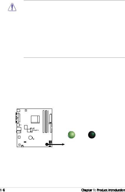
Onboard LED
The motherboard comes with a standby power LED that lights up to indicate that the system is ON, in sleep mode, or in soft-off mode. This is a reminder that you should shut down the system and unplug the power cable before removing or plugging in any motherboard component. The illustration below shows the location of the onboard LED.
SB_PWR
|
|
|
|
|
|
|
|
|
|
|
|
|
|
|
|
|
|
|
|
ON |
OFF |
|
|
|
|
|
|
|
|
|
|
|
|
|
|
|
|
|
|
|
|
||
|
|
|
|
|
|
|
|
|
|
|
|
|
|
|
|
|
|
|
|
||
|
|
|
|
|
|
|
|
|
|
|
|
|
|
|
|
|
|
|
|
||
|
|
|
|
|
|
|
|
|
|
|
|
|
|
|
|
|
|
|
|
||
|
|
|
|
|
|
|
|
|
|
|
|
|
|
|
|
|
|
|
|
Standby |
Powered |
|
|
|
|
|
|
|
|
|
|
|
|
|
|
|
|
|
|
|
|
||
|
|
|
|
|
|
|
|
|
|
|
|
|
|
|
|
|
|
|
|
Power |
Off |
M2N8-VMX Onboard LED
1- |
Chapter 1: Product introduction |
1.5Motherboard overview
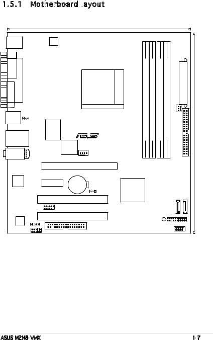
1.5.1 Motherboard layout

|
|
|
|
|
|
22.4cm (8.8in) |
|
|
|
|
|
|
PS/2KBMS |
|
|
|
|
|
|
|
|
|
|
|
|
T: Mouse |
|
|
|
|
|
|
|
|
|
|
|
|
B: Keyboard |
|
ATX12V |
|
|
|
|
|
|
|
|
|
|
|
|
|
|
|
|
|
|
|
|
|
|
|
VGA COM1 |
PARALLEL PORT |
|
|
|
|
Socket M2 |
(64 bit,240-pin module) |
(64 bit,240-pin module) |
(64 bit,240-pin module) |
(64 bit,240-pin module) |
FAN |
EATXPWR |
LAN_USB34 |
|
|
|
|
|
A1 |
B1 |
A2 |
B2 |
CHA_ |
24.5cm(9.6in) |
|
|
|
|
|
|
DDR2DIMM |
DDR2DIMM |
DDR2DIMM |
DDR2DIMM |
IDEPRI |
|||
USB12 |
|
|
|
|
|
|
|
|
|
|
|
|
|
PS2_USB_PWR |
|
|
|
|
|
|
|
|
|
|
|
|
|
|
Super I/O |
|
|
|
|
|
|
|
|
|
|
|
|
|
|
|
R |
|
|
|
|
|
|
|
|
|
4Mb BIOS |
M2N8-VMX |
|
|
|
|
|
|
||
|
|
|
|
|
|
|
|
|
|
|
||
AUDIO |
CD |
|
|
|
|
|
|
|
|
|
|
|
|
|
|
|
CPU_FAN |
|
|
|
|
|
|
||
|
|
|
|
PCIEX8 |
|
|
|
|
|
|
|
|
|
Attansic |
|
|
CR2032 3V |
|
|
|
|
|
|
|
|
|
L1 |
|
PCIEX1_1 |
|
|
|
|
|
|
|
|
|
|
|
Lithium Cell |
|
|
|
|
|
|
|
|
||
|
|
|
|
CMOS Power |
CLRTC |
Nvidia |
|
|
|
|
|
|
|
|
|
|
|
|
|
MCP61S |
|
|
|
|
|
|
|
|
|
PCI1 |
|
|
|
|
|
|
|
|
|
|
|
USB56 |
|
|
|
|
|
|
|
SATA1 |
SATA2 |
|
|
|
|
|
|
|
|
|
|
|
|
|
|
|
|
|
PCI2 |
|
|
|
|
|
|
|
|
|
ALC883 |
SPDIF_OUT |
|
|
|
|
|
SB_PWR |
|
PANEL |
|
|
|
|
|
|
|
|
|
|
|
|
|
||
|
|
|
|
|
|
|
|
|
|
|
|
|
|
AAFP |
FLOPPY |
|
|
|
|
|
|
USB78 |
|||
ASUS M2N8-VMX |
1- |
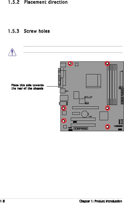
1.5.2 Placement direction
When installing the motherboard, make sure that you place it into the chassis in the correct orientation. The edge with external ports goes to the rear part of the chassis as indicated in the image below.
1.5.3 Screw holes
Place six (6) screws into the holes indicated by circles to secure the motherboard to the chassis.
Do not overtighten the screws! Doing so can damage the motherboard.
Place this side towards the rear of the chassis
M2N8-VMX |
1- |
Chapter 1: Product introduction |
1.6Central Processing Unit (CPU)
The motherboard comes with a 940-pin AM2 socket designed for the AMD Athlon™ 64 X2/Athlon™ 64/Athlon™ FX/Sempron™ processor.
Make sure you use a CPU designed for the AM2 socket. The CPU fits in only one correct orientation. DO NOT force the CPU into the socket to prevent bending the connectors on the socket and damaging the CPU!
1.6.1 Installing
 the CPU
To install a CPU.
1.Locate the CPU socket on the motherboard.
M2N8-VMX CPU Socket M2
2.Unlock the socket by pressing the lever sideways, then lift it up to a 90°-100° angle.
Socket lever

Make sure that the socket lever is lifted up to 90°-100° angle, otherwise the CPU does not fit in completely.
ASUS M2N8-VMX |
1- |
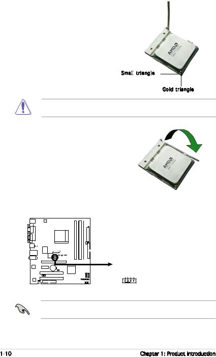
3.Position the CPU above the socket such that the CPU corner with the gold triangle matches the socket corner with a small triangle.
4.Carefully insert the CPU into the socket until it fits in place.
Small
 triangle
Gold triangle
The CPU fits only in one correct orientation. DO NOT force the CPU into the socket to prevent bending the pins and damaging the CPU!
5.When the CPU is in place, push down the socket lever to secure the CPU. The lever clicks on the side tab to indicate that it is locked.
6.Install a CPU heatsink and fan following the instructions that came with the heatsink package.
7.Connect the CPU fan cable to the CPU_FAN connector on the motherboard.
CPU_FAN
CPU FAN PWM
CPU FAN IN
CPU FAN PWR
GND
M2N8-VMX CPU Fan Connector
Do not forget to connect the CPU fan connector! Hardware monitoring errors can occur if you fail to plug this connector.
1-10 |
Chapter 1: Product introduction |
1.6.2 Installing the heatsink and fan
The AMD Athlon™ 64 X2/Athlon™ 64/Athlon™ FX/Sempron™ processor require a specially designed heatsink and fan assembly to ensure optimum thermal condition and performance.
Make sure that you use only qualified heatsink and fan assembly.
Follow these steps to install the CPU heatsink and fan.
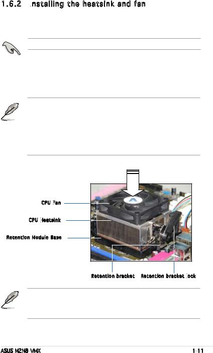
1.Place the heatsink on top of the installed CPU, making sure that the heatsink fits properly on the retention module base.
•The retention module base is already installed on the motherboard
upon purchase.
• You do not have to remove the retention module base when installing the CPU or installing other motherboard components.
•If you purchased a separate CPU heatsink and fan assembly, make sure that a Thermal Interface Material is properly applied to the CPU heatsink or CPU before you install the heatsink and fan assembly.
CPU Fan

CPU Heatsink

Retention Module Base
Retention bracket Retention bracket lock

Your boxed CPU heatsink and fan assembly should come with installation instructions for the CPU, heatsink, and the retention mechanism. If the instructions in this section do not match the CPU documentation, follow the latter.
ASUS M2N8-VMX |
1-11 |

2.Attach one end of the retention bracket to the retention module base.
3.Align the other end of the retention bracket (near the retention bracket lock) to the retention module base. A clicking sound denotes that the retention bracket is in place.
Make sure that the fan and heatsink assembly perfectly fits the retention mechanism module base; otherwise, you cannot snap the retention bracket in place.
4.Push down the retention bracket lock on the retention mechanism to secure the heatsink and fan to the module base.
1-12 |
Chapter 1: Product introduction |
1.7System memory
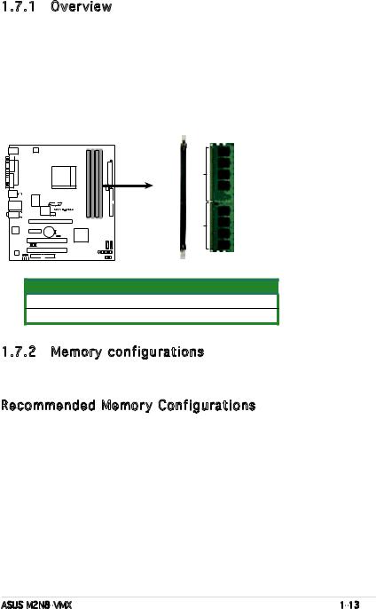
1.7.1 Overview
The motherboard comes with four Double Data Rate 2 (DDR2) Dual Inline Memory Modules (DIMM) sockets.
A DDR2 module has the same physical dimensions as a DDR DIMM but has a 240-pin footprint compared to the 184-pin DDR DIMM. DDR2 DIMMs are notched differently to prevent installation on a DDR DIMM socket.
The figure illustrates the location of the DDR2 DIMM sockets:
|
DIMM A1 DIMM B1 DIMM A2 DIMM B2 |
|
128 Pins |
|
112 Pins |
M2N8-VMX 240-pin DDR2 DIMM Sockets |
|
Channel |
Sockets |
Channel A |
DIMM_A1 and DIMM_A2 |
Channel B |
DIMM_B1 and DIMM_B2 |
1.7.2 Memory configurations
You may install 256 MB, 512 MB, 1 GB, and 2 GB unbuffered/ECC or NonECC DDR2 DIMMs into the DIMM sockets.
Recommended Memory Configurations
|
|
Sockets |
|
||
Mode |
DIMM_A1 |
DIMM_A2 |
DIMM_B1 |
DIMM_B2 |
|
|
Populated |
- |
- |
- |
|
|
|||||
Single Channel |
- |
Populated |
- |
- |
|
- |
- |
Populated |
- |
||
|
|||||
|
- |
- |
- |
Populated |
|
Dual-channel (1) |
Populated |
- |
Populated |
- |
|
- |
Populated |
- |
Populated |
||
|
|||||
Dual-channel (2) |
Populated |
Populated |
Populated |
Populated |
|
ASUS M2N8-VMX |
1-13 |
*For dual-channel memory configuration (2), you may:
• install identical DIMMs in all four sockets OR
•install an identical DIMM pair in DIMM_A1 and DIMM_B1 (yellow sockets) and another identical DIMM pair in DIMM_A2 and DIMM_B2 (black sockets)
*Always use identical DDR2 DIMM pairs for dual-channel model. For optimum compatibility, we recommend that you obtain memory modules from the same vendor. Visit the ASUS website (www.asus. com) for the latest Qualified Vendors List.
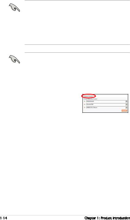
Important notice on installing Windows® XP 32-bit version
If you install Windows® XP 32-bit version Operating System (OS), the limitation of this OS version is that it may reserve a certain amount of memory space for system devices. We recommend that you install less than 3 GB system memory if you would like to work under Windows® XP 32-bit version OS. The excess memory installation will not cause any usage problem, but it will not give users the benefit of manipulating this excess memory space.
Visit the ASUS FAQ site for further explanation: http://support.asus.com/faq/faq. aspx?SLanguage=en-us
Under General Search, make the selections as shown, then click Search. Click the article titled “4GB
memory installed but less memory size detected.”
You also may check the URLs below for third party comments on this issue:
http://dlsvr01.asus.com/pub/ASUS/mb/4GB_Rev1.pdf http://www.intel.com/support/motherboards/server/sb/cs-016594.htm
|
32-bit |
64-bit |
|
|
Windows® 2000 Advanced Server |
Windows® Server 2003 Standard |
|
|
Windows® Server 2003 Enterprise |
x64 Edition |
|
|
Edition |
Windows® XP Professtional x64 |
|
|
|
Edition |
|
|
|
Windows® Server 2003 Enterprise |
|
|
|
x64 Edition |
|
|
|
|
|
1-14 |
Chapter 1: Product introduction |
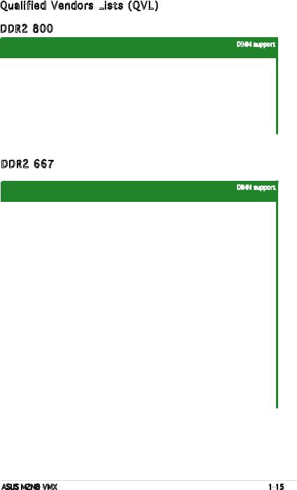
Qualified Vendors Lists
 (QVL)
(QVL)
DDR2 800
DIMM support
Size |
Vendor |
Model |
Brand |
Side(s) |
Component |
A |
B |
|
512MB |
Kingston |
KVR800D2N5/512 |
Samsung |
SS |
K4T51083QC-ZCE7 |
• |
• |
|
1G |
Kingston |
KVR800D2N5/1G |
Samsung |
DS |
K4T51083QC-ZCE7 |
• |
• |
|
1G |
Kingston |
KHX6400D2LL/1G |
Kingston |
DS |
Heat-Sink Package |
|
|
|
512MB |
Samsung |
KR M378T6553CZ3-CE7 |
Samsung |
SS |
K4T51083QC-ZCE7 |
• |
• |
|
1G |
Samsung |
KR M378T2953CZ3-CE7 |
Samsung |
DS |
K4T51083QC-ZCE7 |
• |
• |
|
512MB |
Samsung |
KR M391T6553CZ3-CE7 |
Samsung |
SS |
K4T51083QC-ZCE7(ECC) |
• |
• |
|
1G |
Samsung |
KR M391T2953CZ3-CE7 |
Samsung |
DS |
K4T51083QC-ZCE7(ECC) |
• |
• |
|
256MB |
Infineon |
HYS64T32001HU-2.5-A |
Infineon |
SS |
HYB18T256800AF25SSS49313 |
• |
• |
|
512MB |
Infineon |
HYS64T64020HU-2.5-A |
Infineon |
DS |
HYB18T256800AF25SSS25063 |
• |
• |
|
512MB |
HY |
HYMP564U64AP8-S6 AA |
Hynix |
SS |
HY5PS12821AFP-S6 |
• |
• |
|
1G |
HY |
HYMP512U64AP8-S6 AA |
Hynix |
DS |
HY5PS12821AFP-S6 |
|
|
|
DDR2 667
DIMM support
Size |
Vendor |
ChipModelNo |
BrandSide(s)Side(s)Part NoComponent. |
A |
AB |
BC |
|||
256MB |
Kingston |
KVR667D2N5/256 |
Elpida |
SS |
E2508AB-6E-E |
|
• |
• |
|
512MB |
Kingston |
KVR667D2N5/512 |
Kingston |
SS |
D6408TE8WL-27 |
|
• |
• |
|
512MB |
Kingston |
KVR667D2E5/512 |
Elpida |
SS |
E5108AE-6E-E(ECC) |
|
• |
• |
|
1G |
Kingston |
KVR667D2N5/1G |
Kingston |
DS |
D6408TE8WL-3 |
|
• |
• |
|
512MB |
Samsung |
KR M378T6553CZ0-CE6 |
Samsung |
SS |
K4T51083QC |
|
• |
• |
|
512MB |
Samsung |
KR M378T6453FZ0-CE6 |
Samsung |
DS |
K4T56083QF-ZCE6 |
|
• |
• |
|
512MB |
Samsung |
M378T6553CZ3-CE6 |
Samsung |
SS |
K4T51083QC-ZCE6 |
|
• |
• |
|
1G |
Samsung |
M378T2953CZ3-CE6 |
Samsung |
DS |
K4T51083QC-ZCE6 |
|
• |
• |
|
1G |
Samsung |
KR M378T2953CZ0-CE6 |
Samsung |
SS |
K4T51083QC-ZCE6 |
|
• |
• |
|
256MB |
Infineon |
HYS64T32000HU-3S-A |
Infineon |
SS |
HYB18T512160AF-3SSSS17310 |
• |
• |
|
|
512MB |
Infineon |
HYS64T32000HU-3S-A |
Infineon |
SS |
HYB18T5128000AF-3SSSS27416 |
• |
• |
|
|
512MB |
Infineon |
HYS64T64000HU-3S-A |
Infineon |
SS |
HYB18T512800AF3SFSS05346 |
|
• |
• |
|
1G |
Infineon |
HYS64T128020HU-3S-A |
Infineon |
DS |
HYB18T512800AF3SSSS28104 |
• |
• |
|
|
512MB |
HY |
HYMP564U64AP8-Y4 AA |
Hynix |
SS |
HY5PS12821AFP-Y4 |
|
• |
• |
|
512MB |
HY |
HYMP564U64AP8-Y5 AA |
Hynix |
SS |
HY5PS12821AFP-Y5 |
|
• |
• |
|
512MB |
HY |
HYMP564U72AP8-Y4 |
Hynix |
SS |
HY5PS12821AFP-Y4(ECC) |
|
• |
• |
|
512MB |
HY |
HYMP564U72AP8-Y5 |
Hynix |
SS |
HY5PS12821AFP-Y5(ECC) |
|
• |
• |
|
1G |
HY |
HYMP512U72AP8-Y5 |
Hynix |
DS |
HY5PS12821AFP-Y5(ECC) |
|
• |
• |
|
1G |
HY |
HYMP512U64AP8-Y5 AB |
Hynix |
DS |
HY5PS12821AFP-Y5 |
|
• |
• |
|
512MB |
Kingmax |
KLCC28F-A8EB5 |
Elpida |
SS |
E5108AE-6E-E |
|
• |
• |
|
512MB |
Kingmax |
KLCC28F-A8KB5 |
Kingmax |
SS |
KKEA88B4LAUG-29DX |
|
• |
• |
|
1G |
Kingmax |
KLCD48F-A8KB5 |
Kingmax |
DS |
KKEA88B4LAUG-29DX |
|
• |
• |
|
512MB |
Apacer |
78.91092.420 |
Elpida |
SS |
E5108AE-6E-E |
|
• |
• |
|
512MB |
Apacer |
AU512E667C5KBGC |
Apacer |
SS |
AM4B5708MIJS7E0627B |
|
• |
• |
|
1G |
Apacer |
78.01092.420 |
Elpida |
DS |
E5108AE-6E-E |
|
• |
• |
|
1G |
Apacer |
AU01GE667C5KBGC |
Apacer |
DS |
AM4B5708MIJS7E0627B |
|
• |
• |
|
512MB |
ADATA |
M20EL5G3H3160B1C0Z |
Elpida |
SS |
E5108AE-6E-E |
|
• |
• |
|
512MB |
VDATA |
M2GVD5G3H31A4I1C52 |
VDATA |
SS |
VD29608A8A-3EC20615 |
|
• |
• |
|
512MB |
VDATA |
M2YVD5G3H31P4I1C52 |
VDATA |
SS |
VD29608A8A-3EG20627 |
|
• |
• |
|
1G |
VDATA |
M2GVD5G3I41P6I1C52 |
VDATA |
DS |
VD29608A8A-3EG20627 |
|
• |
• |
|
1G |
VDATA |
M2GVD5G3I41C4I1C52 |
VDATA |
DS |
VD29608A8A-3EC20620 |
|
• |
• |
|
ASUS M2N8-VMX |
1-15 |
 Loading...