


Copyright Notice:
No part of this installation guide may be reproduced, transcribed, transmitted, or translated in any language, in any form or by any means, except duplication of documentation by the purchaser for backup purpose, without written consent of ASRock Inc.
Products and corporate names appearing in this guide may or may not be registered trademarks or copyrights of their respective companies, and are used only for identification or explanation and to the owners’ benefit, without intent to infringe.
Disclaimer:
Specifications and information contained in this guide are furnished for informational use only and subject to change without notice, and should not be constructed as a commitment by ASRock. ASRock assumes no responsibility for any errors or omissions that may appear in this guide.
With respect to the contents of this guide, ASRock does not provide warranty of any kind, either expressed or implied, including but not limited to the implied warranties or conditions of merchantability or fitness for a particular purpose. In no event shall ASRock, its directors, officers, employees, or agents be liable for any indirect, special, incidental, or consequential damages (including damages for loss of profits, loss of business, loss of data, interruption of business and the like), even if ASRock has been advised of the possibility of such damages arising from any defect or error in the guide or product.
This device complies with Part 15 of the FCC Rules. Operation is subject to the following two conditions:
(1)this device may not cause harmful interference, and
(2)this device must accept any interference received, including interference that may cause undesired operation.
CALIFORNIA, USA ONLY
The Lithium battery adopted on this motherboard contains Perchlorate, a toxic substance controlled in Perchlorate Best Management Practices (BMP) regulations passed by the California Legislature. When you discard the Lithium battery in California, USA, please follow the related regulations in advance.
“Perchlorate Material-special handling may apply, see www.dtsc.ca.gov/hazardouswaste/perchlorate”
ASRock Website: http://www.asrock.com
Published July 2013
Copyright©2013 ASRock INC. All rights reserved.
1
English
ASRock FM2A75 Pro4-M Motherboard

English
Motherboard Layout
|
|
|
|
|
|
1 |
2 |
|
3 |
4 |
5 |
6 |
|
|
|
7 |
8 |
|
|
|
|
|
|
|
|
|
|
|
24.4cm (9.6-in) |
|
|
|
|
|
|
|
|
|
|
|
|
|
|
|
|
|
Keyboard/ |
|
|
|
Designed in Taipei |
|
|
|
|
|
|
|
|
|
|
|
|
|
|
USB 3.0 |
Mouse |
Ps2 |
|
|
|
|
|
|
|
|
|
|
|
|
|
|
|
|
-in) |
||
T: USB1 |
|
PWR_FAN1 |
|
|
|
|
|
|
|
|
|
|
|
|
|
|
|||||
B: USB2 |
|
|
|
|
|
|
CPU_FAN2 |
|
|
|
|
|
|
|
|
||||||
|
|
|
|
|
|
|
|
CPU_FAN1 |
|
|
|
|
|
|
|
|
|||||
|
|
|
|
|
|
|
|
|
|
|
DX11 |
|
|
|
|
|
|
||||
|
|
|
|
|
|
|
|
|
|
|
|
|
|
|
|
|
|
|
|
(9.6 |
|
|
|
|
|
|
|
|
|
|
|
|
|
DDR3 2600+ |
|
|
|
|
|
|
|||
|
|
|
|
|
|
|
ATX12V1 |
|
|
|
|
|
|
|
|
|
|
|
|
|
24.4cm |
|
|
DVICON1 |
|
|
|
|
|
|
|
|
|
|
|
DDR3 A1(64bit,240-pinmodule) |
DDR3 A2(64bit,240-pinmodule) |
DDR3 B1(64bit,240-pinmodule) |
DDR3 B2(64bit,240-pinmodule) |
|
|
||
HDMI1 |
|
|
|
|
|
|
|
|
|
|
|
2FM SOCKET |
|
|
|
ATXPWR1 |
|
||||
eSATA |
USB 2.0 |
|
DualGraphics |
|
|
|
|
|
|
|
|
|
|
||||||||
T: USB1 |
|
|
|
|
|
|
|
|
|
|
9 |
||||||||||
B: USB2 |
|
|
|
|
|
|
|
|
|
|
|||||||||||
|
|
|
|
|
|
|
|
|
|
|
|||||||||||
|
|
|
|
|
|
|
|
|
|
|
|
|
|
||||||||
USB 2.0 |
|
Top: |
|
|
|
|
|
|
|
|
|
|
|||||||||
T: USB3 |
|
Ready |
|
|
|
|
|
|
|
|
|
||||||||||
B: USB4 |
|
RJ-45 |
|
|
|
|
|
|
|
|
|
||||||||||
|
|
|
|
|
|
|
|
|
|
|
|
|
|
||||||||
SPDIF Optical Bottom : |
REARSPK |
Center: |
|
CTR Top: BASS |
LAN |
ErP/EuP |
|
|
|
|
|
|
|
|
|
|
|
|
|
|
|
|
|
|
|
|
|
|
|
|
|
|
|
|
|
3 4 |
|
10 |
|||||
MI Bottom CIN : |
FRON Center: T |
|
LINE Top: IN |
|
|
FM2A75 Pro4-M |
|
|
|
|
|
|
|
USB3 |
|
||||||
|
XFast LAN |
|
|
|
|
|
|
|
|
|
|||||||||||
|
|
|
|
|
|
|
|
|
|
|
|
|
|
|
|||||||
35 |
|
|
|
|
|
|
PCIE1 |
|
|
|
|
|
|
|
|
|
Front USB 3.0 |
1 |
|
||
|
|
|
|
|
|
|
|
|
|
|
|
|
|
|
|
|
|||||
|
|
|
|
|
|
|
|
|
|
|
|
|
|
|
|
|
|
|
|
||
34 |
|
|
|
|
|
|
|
|
|
|
|
|
|
|
|
|
|
|
|
|
|
|
|
Super |
|
PCIE2 |
|
CMOS |
|
|
|
|
AMD |
|
|
|
|
|
11 |
||||
|
|
|
|
BATTERY |
|
|
|
|
|
|
|
|
|
|
|||||||
|
|
|
I/O |
|
|
|
|
|
|
|
|
|
|
|
|
|
|||||
33 |
|
|
|
|
|
CI1 |
|
|
|
1 |
XFast USB |
A75 FCH |
|
|
|
|
12 |
||||
|
|
|
|
|
1 |
|
|
|
CLRCMOS1 |
|
|
(Hudson-D3) |
|
|
|
|
|||||
|
|
|
|
|
|
|
|
|
|
|
|
|
|
|
CHA_FAN1 |
|
|||||
32 |
|
|
|
|
|
|
PCIE3 |
|
|
|
|
|
|
Chipset |
|
|
|
|
|
||
|
|
|
|
|
|
|
|
RoHS |
|
|
|
|
|
|
|
|
|
|
64Mb |
13 |
|
|
|
|
|
|
|
|
XFast RAM |
|
|
|
|
|
|
|
|
|
|
BIOS |
|||
|
|
|
|
|
|
|
|
|
|
|
|
|
|
|
|
|
|
|
|
|
|
|
AUDIO |
|
|
|
PCI1 |
|
|
|
|
|
SPEAKER1 |
|
|
|
|
|
|
14 |
|||
|
CODEC |
|
|
|
|
|
|
|
|
1 |
|
|
|
SATA3_5 |
|
SATA3_4 |
|
||||
31 |
|
|
|
|
|
|
|
|
|
|
|
|
PLED1 |
|
|
|
|
|
|||
|
|
|
|
|
|
LPT1 |
|
USB9_10 |
USB7_8 |
|
USB5_6 |
1PLED PWRBTN |
|
|
|
|
|
|
15 |
||
HD_AUDIO1 |
|
IR1 |
COM1 |
|
|
|
|
|
|
|
|
|
|
|
|
|
|
||||
|
|
|
1 |
|
|
1 |
|
|
1 |
1 |
1 |
|
1 |
|
|
|
|
|
|
|
16 |
1 |
|
|
|
|
|
|
1 |
|
|
|
HDLED RESET |
|
|
|
|
|
|
||||
|
|
|
|
|
|
|
|
|
|
|
|
|
PANEL 1 |
SATA3_3 |
SATA3_2 |
SATA3_1 |
|
|
|||
30 |
|
29 |
28 |
|
27 |
26 |
25 |
24 23 22 |
21 |
2019 |
|
18 |
|
17 |
|
|
|
||||
1 |
Power Fan Connector (PWR_FAN1) |
18 |
SATA3 Connector (SATA3_3, Grey) |
2 |
ATX 12V Power Connector (ATX12V1) |
19 |
Chassis Speaker Header (SPEAKER1) |
3 |
CPU Heatsink Retention Module |
20 |
Power LED Header (PLED1) |
4 |
CPU Socket |
21 |
System Panel Header (PANEL1) |
5 |
CPU Fan Connector (CPU_FAN1) |
22 |
USB 2.0 Header (USB5_6, Black) |
6 |
CPU Fan Connector (CPU_FAN2) |
23 |
Clear CMOS Jumper (CLRCMOS1) |
7 |
2 x 240-pin DDR3 DIMM Slots |
24 |
USB 2.0 Header (USB7_8, Black) |
|
(DDR3_A1, DDR3_B1, Black) |
25 |
Consumer Infrared Module Header |
8 |
2 x 240-pin DDR3 DIMM Slots |
|
(CIR1, Gray) |
|
(DDR3_A2, DDR3_B2, Black) |
26 |
USB 2.0 Header (USB9_10, Black) |
9 |
ATX Power Connector (ATXPWR1) |
27 |
Print Port Header (LPT1) |
10 |
USB 3.0 Header (USB3_3_4, Black) |
28 |
COM Port Header (COM1) |
11 |
Southbridge Controller |
29 |
Infrared Module Header (IR1) |
12 |
Chassis Fan Connector (CHA_FAN1) |
30 |
Front Panel Audio Header (HD_AUDIO1) |
13 |
SPI Flash Memory (64Mb) |
31 |
PCI Slot (PCI1) |
14 |
SATA3 Connector (SATA3_5, Grey) |
32 |
PCI Express 2.0 x16 Slot (PCIE3) |
15 |
SATA3 Connector (SATA3_4, Grey) |
33 |
Chassis Intrusion Header (CI1) |
16 |
SATA3 Connector (SATA3_1, Grey) |
34 |
PCI Express 2.0 x1 Slot (PCIE2) |
17 |
SATA3 Connector (SATA3_2, Grey) |
35 |
PCI Express 2.0 x16 Slot (PCIE1) |
2
ASRock FM2A75 Pro4-M Motherboard
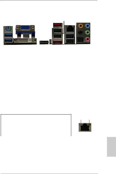
I/O Panel
1 |
2 |
|
3 |
4 |
|
|
|
|
|
|
|
|
|
|
|
|||||||||||
|
|
|
|
|
|
|
|
|
|
|
|
|
|
|
|
|
|
|
|
|
5 |
|
|
8 |
||
|
|
|
|
|
|
|
|
|
|
|
|
|
|
|
|
|
|
|
|
|
|
|
||||
|
|
|
|
|
|
|
|
|
|
|
|
|
|
|
|
|
|
|
|
|
|
|
||||
|
|
|
|
|
|
|
|
|
|
|
|
|
|
|
|
|
|
|
|
|
||||||
|
|
|
|
|
|
|
|
|
|
|
|
|
|
|
|
|
|
|
|
|||||||
|
|
|
|
|
|
|
|
|
|
|
|
|
|
|
|
|
|
|
|
|
|
6 |
|
|
|
9 |
|
|
|
|
|
|
|
|
|
|
|
|
|
|
|
|
|
|
|
||||||||
|
|
|
|
|
|
|
|
|
|
|
|
|
|
|
|
|
|
|
|
|
|
|
|
|||
|
|
|
|
|
|
|
|
|
|
|
|
|
|
|
|
|
|
|
|
|
7 |
|
|
10 |
||
|
|
|
|
|
|
|
|
|
|
|
|
|
|
|
|
|
|
|
|
|
|
|||||
|
|
|
|
|
|
|
|
|
|
|
|
|
|
|
|
|
|
|
|
|
|
|||||
|
|
|
|
|
|
|
|
|
|
|
|
|
|
|
|
|
|
|
|
|
|
|
||||
|
|
|
|
|
|
|
|
|
|
|
|
|
|
|
|
|
|
|
|
|
|
|
|
|
|
|
|
|
|
|
|
|
|
|
|
|
|
|
|
|
|
|
|
|
|
|
|
|
|
|
|
|
|
|
|
|
|
|
|
|
|
|
|
|
|
|
|
|
|
|
|
|
|
|
|
|
|
|
|
|
|
15 |
14 |
13 |
12 |
11 |
|
1 |
PS/2 Mouse/Keyboard Port |
|
8 |
Line In (Light Blue) |
||
|
(Green/Purple) |
|
|
** 9 |
Front Speaker (Lime) |
|
2 |
D-Sub Port (VGA) |
|
10 |
Microphone (Pink) |
||
3 |
USB 2.0 Ports (USB_1_2) |
|
11 |
USB 2.0 |
Ports (USB_3_4) |
|
* 4 LAN RJ-45 Port |
|
|
*** 12 |
eSATA3 Connector |
||
5 |
Central / Bass (Orange) |
|
13 |
HDMI Port |
||
6 |
Rear Speaker (Black) |
|
14 |
DVI-D Port |
||
7 |
Optical SPDIF Out Port |
|
15 |
USB 3.0 |
Ports (USB3_1_2) |
|
*There are two LEDs on each LAN port. Please refer to the table below for the LAN port LED indications.
LAN Port LED Indications
|
Activity/Link LED |
|
SPEED LED |
|
Status |
|
Description |
Status |
Description |
Off |
|
No Link |
Off |
10Mbps connection |
Blinking |
Data Activity |
Orange |
100Mbps connection |
|
On |
|
100Mbps connection |
Green |
1Gbps connection |
ACT/LINK SPEED LED LED
LAN Port
English
3
ASRock FM2A75 Pro4-M Motherboard
**If you use a 2-channel speaker, please connect the speaker’s plug into “Front Speaker Jack”. See the table below for connection details in accordance with the type of speaker you use.
TABLE for Audio Output Connection
Audio Output |
Front Speaker |
Rear Speaker |
Central / Bass |
Line In |
Channels |
(No. 9) |
(No. 6) |
(No. 5) |
(No. 8) |
2 |
V |
-- |
-- |
-- |
4 |
V |
V |
-- |
-- |
6 |
V |
V |
V |
-- |
8 |
V |
V |
V |
V |
To enable Multi-Streaming function, you need to connect a front panel audio cable to the front panel audio header. After restarting your computer, you will find “Mixer” tool on your system. Please select “Mixer ToolBox” , click “Enable playback multi-streaming”, and click “ok”.
Choose “2CH”, “4CH”, “6CH”, or “8CH” and then you are allowed to select “Realtek HDA Primary output” to use Rear Speaker, Central/Bass, and Front Speaker, or select “Realtek HDA Audio 2nd output” to use front panel audio.
*** eSATA3 connector supports SATA Gen3 in cable 1M.
English
4
ASRock FM2A75 Pro4-M Motherboard

1. Introduction
Thank you for purchasing ASRock FM2A75 Pro4-M motherboard, a reliable motherboard produced under ASRock’s consistently stringent quality control. It delivers excellent performance with robust design conforming to ASRock’s commitment to quality and endurance.
In this manual, chapter 1 and 2 contains the introduction of the motherboard and step-by-step hardware installation guide. Chapter 3 and 4 contains the configuration guide of BIOS setup and information of the Support
CD.
Because the motherboard specifications and the BIOS software might be updated, the content of this manual will be subject to change without notice. In case any modifications of this manual occur, the updated version will be available on ASRock’s website without further notice. You may find the latest VGA cards and CPU support list on ASRock’s website as well. ASRock website http://www.asrock.com
If you require technical support related to this motherboard, please visit our website for specific information about the model you are using.
www.asrock.com/support/index.asp
1.1 Package Contents
ASRock FM2A75 Pro4-M Motherboard
(Micro ATX Form Factor: 9.6-in x 9.6-in, 24.4 cm x 24.4 cm) ASRock FM2A75 Pro4-M Quick Installation Guide
ASRock FM2A75 Pro4-M Support CD
2 x Serial ATA (SATA) Data Cables (Optional)
1 x I/O Panel Shield
English
5
ASRock FM2A75 Pro4-M Motherboard

English
6
1.2 Specifications
Platform |
- Micro ATX Form Factor: 9.6-in x 9.6-in, 24.4 cm x |
|
24.4 cm |
|
- All Solid Capacitor design |
CPU |
- Support for Socket FM2 100W processors |
|
- 4 + 2 Power Phase Design |
|
- Supports AMD’s Cool ‘n’ QuietTM Technology |
|
- UMI-Link GEN2 |
Chipset |
- AMD A75 FCH (Hudson-D3) |
Memory |
- Dual Channel DDR3 Memory Technology |
|
- 4 x DDR3 DIMM slots |
|
- Support DDR3 2600+(OC)/2400(OC)/2133(OC)/1866/ |
|
1600/1333/1066/800 non-ECC, un-buffered memory |
|
(see CAUTION 1) |
|
- Max. capacity of system memory: 64GB |
|
(see CAUTION 2) |
|
- Supports Intel® Extreme Memory Profile (XMP) 1.3 / |
|
1.2 |
|
- Supports AMD Memory Profile (AMP) |
Expansion Slot |
- 2 x PCI Express 2.0 x16 slots (PCIE1 @ x16 mode; |
|
PCIE3 @ x4 mode) |
|
- 1 x PCI Express 2.0 x1 slot |
|
- 1 x PCI slot |
|
- Supports AMD Quad CrossFireXTM, CrossFireXTM and |
|
Dual Graphics |
Graphics |
- AMD Radeon HD 7000 series graphics |
|
- DirectX 11, Pixel Shader 5.0 |
|
- Max. shared memory 2GB |
|
- Three VGA Output options: D-Sub, DVI-D and HDMI |
|
- Supports HDMI 1.4a Technology with max. resolution |
|
up to 1920x1200 @ 60Hz |
|
- Supports Dual-link DVI with max. resolution up to |
|
2560x1600 @ 75Hz |
|
- Supports D-Sub with max. resolution up to 1920x |
|
1600 @ 60Hz |
|
|
ASRock FM2A75 Pro4-M Motherboard

|
|
|
- Supports Auto Lip Sync, Deep Color (12bpc), xvYCC |
|
and HBR (High Bit Rate Audio) with HDMI |
|
(see CAUTION 3) |
|
- Supports Blu-ray Stereoscopic 3D with HDMI 1.4a |
|
- Supports AMD Steady VideoTM: New video post |
|
processing capability for automatic jutter reduction on |
|
home/online video |
|
- Supports HDCP with DVI and HDMI ports |
|
- Supports Full HD 1080p Blu-ray (BD) / HD-DVD |
|
playback with DVI and HDMI ports |
|
|
Audio |
- 7.1 CH HD Audio with Content Protection |
|
(Realtek ALC892 Audio Codec) |
|
- Premium Blu-ray audio support |
LAN |
- PCIE x1 Gigabit LAN 10/100/1000 Mb/s |
|
- Realtek RTL8111E |
|
- Supports Wake-On-LAN |
|
- Supports LAN Cable Detection |
|
- Supports Energy Efficient Ethernet 802.3az |
|
- Supports PXE |
Rear Panel I/O |
I/O Panel |
|
- 1 x PS/2 Mouse/Keyboard Port |
|
- 1 x D-Sub Port |
|
- 1 x DVI-D Port |
|
- 1 x HDMI Port |
|
- 1 x Optical SPDIF Out Port |
|
- 4 x Ready-to-Use USB 2.0 Ports |
|
- 1 x eSATA3 Connector |
|
- 2 x Ready-to-Use USB 3.0 Ports |
|
- 1 x RJ-45 LAN Port with LED (ACT/LINK LED and |
|
SPEED LED) |
|
- HD Audio Jack: Rear Speaker/Central/Bass/Line in/ |
|
Front Speaker/Microphone |
SATA3 |
- 5 x SATA3 6.0 Gb/s connectors, support RAID (RAID |
|
0, RAID 1 and RAID 10), NCQ, AHCI and Hot Plug |
USB 3.0 |
- 2 x Rear USB 3.0 ports, support USB 1.1/2.0/3.0 up |
|
to 5Gb/s |
|
|
7
English
ASRock FM2A75 Pro4-M Motherboard

English
|
|
|
- 1 x Front USB 3.0 header (supports 2 USB 3.0 ports), |
|
supports USB 1.1/2.0/3.0 up to 5Gb/s |
|
|
Connector |
- 5 x SATA3 6.0Gb/s connectors |
|
- 1 x IR header |
|
- 1 x CIR header |
|
- 1 x Print port header |
|
- 1 x COM port header |
|
- 1 x Power LED header |
|
- 1 x Chassis Intrusion header |
|
- 2 x CPU Fan connectors (1 x 4-pin, 1 x 3-pin) |
|
- 1 x Chassis Fan connector (4-pin) |
|
- 1 x Power Fan connector (3-pin) |
|
- 24 pin ATX power connector |
|
- 8 pin 12V power connector |
|
- Front panel audio connector |
|
- 3 x USB 2.0 headers (support 6 USB 2.0 ports) |
|
- 1 x USB 3.0 header (supports 2 USB 3.0 ports) |
BIOS Feature |
- 64Mb AMI UEFI Legal BIOS with GUI support |
|
- Supports “Plug and Play” |
|
- ACPI 1.1 Compliance Wake Up Events |
|
- Supports jumperfree |
|
- SMBIOS 2.3.1 Support |
|
- DRAM, VDDP, VDDR, SB Voltage Multi-adjustment |
Support CD |
- Drivers, Utilities, AntiVirus Software (Trial Version), |
|
CyberLink MediaEspresso 6.5 Trial |
Hardware |
- CPU Temperature Sensing |
Monitor |
- Chassis Temperature Sensing |
|
- CPU/Chassis/Power Fan Tachometer |
|
- CPU/Chassis Quiet Fan |
|
- CPU/Chassis Fan Multi-Speed Control |
|
- CASE OPEN detection |
|
- Voltage Monitoring: +12V, +5V, +3.3V, Vcore |
OS |
- Microsoft® Windows® 7 / 7 64-bit / VistaTM / VistaTM |
|
64-bit / XP SP3 compliant |
Certifications |
- FCC, CE, WHQL |
|
- ErP/EuP Ready (ErP/EuP ready power supply is |
|
required) |
8
ASRock FM2A75 Pro4-M Motherboard

*For detailed product information, please visit our website: http://www.asrock.com
WARNING
Please realize that there is a certain risk involved with overclocking, including adjusting the setting in the BIOS, applying Untied Overclocking Technology, or using thirdparty overclocking tools. Overclocking may affect your system’s stability, or even cause damage to the components and devices of your system. It should be done at your own risk and expense. We are not responsible for possible damage caused by overclocking.
English
9
ASRock FM2A75 Pro4-M Motherboard

CAUTION!
1.Whether 2600/2400/2133/1866/1600MHz memory speed is supported depends on the CPU you adopt. If you want to adopt DDR3 2600/2400/2133/1866/1600 memory module on this motherboard, please refer to the memory support list on our website for the compatible memory modules.
ASRock website http://www.asrock.com
2.Due to the operating system limitation, the actual memory size may be less than 4GB for the reservation for system usage under Windows® 7 / VistaTM / XP. For Windows® 64-bit OS with 64-bit CPU, there is no such limitation. You can use ASRock XFast RAM to utilize the memory that Windows® cannot use.
3.xvYCC and Deep Color are only supported under Windows® 7 64-bit / 7. Deep Color mode will be enabled only if the display supports 12bpc in EDID. HBR is supported under Windows® 7 64-bit / 7 / VistaTM 64-bit / VistaTM.
English
10
ASRock FM2A75 Pro4-M Motherboard
1.3 Unique Features
ASRock Extreme Tuning Utility (AXTU)
ASRock Extreme Tuning Utility (AXTU) is an all-in- one tool to ne-tune different system functions in a userfriendly interface, which includes Hardware Monitor, Fan Control, Overclocking, OC DNA, IES and XFast RAM. In Hardware Monitor, it shows the major readings of your system. In Fan Control, it shows the fan speed and temperature for you to adjust. In Overclocking, you are allowed to overclock CPU frequency for optimal system performance. In OC DNA, you can save your OC settings as a profile and share it with your friends. Your friends then can load the OC profile to their own system to get the same OC settings. In IES (Intelligent Energy Saver), the voltage regulator can reduce the number of output phases to improve efficiency when the CPU cores are idle without sacrificing computing performance. In XFast RAM, it fully utilizes the memory space that cannot be used under Windows® OS 32-bit CPU.
ASRock Instant Boot
ASRock Instant Boot allows you to turn on your PC in just a few seconds, provides a much more efficient way to save energy, time, money, and improves system running speed for your system. It leverages the S3 and S4 ACPI features which normally enable the Sleep/Standby and Hibernation modes in Windows® to shorten boot up time. By calling S3 and S4 at specific timing during the shutdown and startup process, Instant Boot allows you to enter your Windows® desktop in a few seconds.
ASRock Instant Flash
ASRock Instant Flash is a BIOS flash utility embedded in Flash ROM. This convenient BIOS update tool allows you to update system BIOS without entering operating systems first like MS-DOS or Windows®. With this utility,
English
11
ASRock FM2A75 Pro4-M Motherboard

English
12
you can press the <F6> key during the POST or the <F2> key to enter into the BIOS setup menu to access ASRock Instant Flash. Just launch this tool and save the new BIOS file to your USB flash drive, floppy disk or hard drive, then you can update your BIOS only in a few clicks without preparing an additional floppy diskette or other complicated flash utility. Please be noted that the USB flash drive or hard drive must use FAT32/16/12 file system.
ASRock APP Charger
If you desire a faster, less restricted way of charging your Apple devices, such as iPhone/iPad/iPod Touch, ASRock has prepared a wonderful solution for you - ASRock APP Charger. Simply install the APP Charger driver, it makes your iPhone charge much quickly from your computer and up to 40% faster than before. ASRock APP Charger allows you to quickly charge many Apple devices simultaneously and even supports continuous charging when your PC enters into Standby mode (S1), Suspend to RAM (S3), hibernation mode (S4) or power off (S5). With APP Charger driver installed, you can easily enjoy the marvelous charging experience.
ASRock XFast USB
ASRock XFast USB can boost USB storage device performance. The performance may depend on the properties of the device.
ASRock XFast LAN
ASRock XFast LAN provides a faster internet access, which includes the benefits listed below. LAN Application Prioritization: You can configure your application’s priority ideally and/or add new programs. Lower Latency in Game: After setting online game’s priority higher, it can lower the latency in games. Traffic Shaping: You can watch Youtube HD videos and download simultaneously.
ASRock FM2A75 Pro4-M Motherboard

Real-Time Analysis of Your Data: With the status window, you can easily recognize which data streams you are transferring currently.
ASRock XFast RAM
ASRock XFast RAM is a new function that is included into ASRock Extreme Tuning Utility (AXTU). It fully utilizes the memory space that cannot be used under Windows® OS 32-bit CPU. ASRock XFast RAM shortens the loading time of previously visited websites, making web surfing faster than ever. And it also boosts the speed of
Adobe Photoshop 5 times faster. Another advantage of ASRock XFast RAM is that it reduces the frequency of accessing your SSDs or HDDs in order to extend their lifespan.
ASRock Crashless BIOS
ASRock Crashless BIOS allows users to update their BIOS without fear of failing. If power loss occurs during the BIOS update process, ASRock Crashless BIOS will automatically finish the BIOS update procedure after regaining power. Please note that BIOS files need to be placed in the root directory of your USB disk. Only USB2.0 ports support this feature.
ASRock OMG (Online Management Guard)
Administrators are able to establish an internet curfew or restrict internet access at specified times via OMG. You may schedule the starting and ending hours of internet access granted to other users. In order to prevent users from bypassing OMG, guest accounts without permission to modify the system time are required.
ASRock Internet Flash
ASRock Internet Flash searches for available UEFI firmware updates from our servers. In other words, the system can auto-detect the latest UEFI from our servers
English
13
ASRock FM2A75 Pro4-M Motherboard

English
14
and flash them without entering Windows® OS. Please note that you must be running on a DHCP configured computer in order to enable this function.
ASRock UEFI System Browser
ASRock UEFI system browser is a useful tool included in graphical UEFI. It can detect the devices and configurations that users are currently using in their PC. With the UEFI system browser, you can easily examine the current system configuration in UEFI setup.
ASRock On/Off Play Technology
ASRock On/Off Play Technology allows users to enjoy the great audio experience from the portable audio devices, such like MP3 player or mobile phone to your PC, even when the PC is turned off (or in ACPI S5 mode)! This motherboard also provides a free 3.5mm audio cable (optional) that ensures users the most convenient computing environment.
ASRock Dehumidifier Function
Users may prevent motherboard damages due to dampness by enabling “Dehumidifier Function”. When enabling Dehumidifier Function, the computer will power on automatically to dehumidify the system after entering S4/ S5 state.
ASRock Easy RAID Installer
ASRock Easy RAID Installer can help you to copy the RAID driver from a support CD to your USB storage device. After copying the RAID driver to your USB storage device, please change “SATA Mode” to “RAID”, then you can start installing the OS in RAID mode.
ASRock Interactive UEFI
ASRock Interactive UEFI is a blend of system configuration tools, cool sound effects and stunning visuals. The
ASRock FM2A75 Pro4-M Motherboard

unprecedented UEFI provides a more attractive interface and brings a lot more amusement.
English
15
ASRock FM2A75 Pro4-M Motherboard

Chapter 2: Installation
This is a micro ATX form factor (9.6" x 9.6", 24.4 x 24.4 cm) motherboard.
Before you install the motherboard, study the configuration of your chassis to ensure that the motherboard fits into it.
Pre-installation Precautions
Take note of the following precautions before you install motherboard components or change any motherboard settings.
1.Make sure to unplug the power cord before installing or removing the motherboard. Failure to do so may cause physical injuries to you and damages to motherboard components.
2.In order to avoid damage from static electricity to the motherboard’s components, NEVER place your motherboard directly on a carpet. Also remember to use a grounded wrist strap or touch a safety grounded object before you handle the components.
3.Hold components by the edges and do not touch the ICs.
4.Whenever you uninstall any components, place them on a grounded anti-static pad or in the bag that comes with the components.
5.When placing screws to secure the motherboard to the chassis, please do not over-tighten the screws! Doing so may damage the motherboard.
English
16
ASRock FM2A75 Pro4-M Motherboard
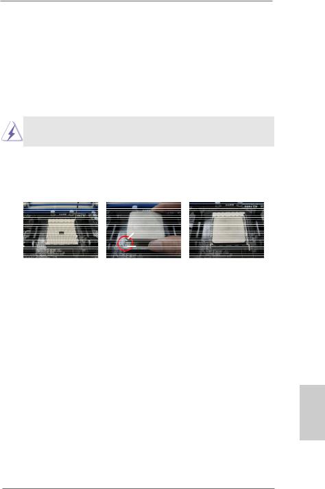
2.1 CPU Installation
Step 1. Unlock the socket by lifting the lever up to a 90o angle.
Step 2. Position the CPU directly above the socket so that the CPU corner with the golden triangle matches the small triangle on the socket’s corner.
Step 3. Carefully insert the CPU into the socket until it fits in place.
The CPU fits only in one correct orientation. DO NOT force the CPU into the socket to avoid bending of the pins.
Step 4. When the CPU is in place, press it firmly on the socket while you push down the socket lever to secure the CPU. The lever clicks on the side tab to indicate that it is locked.
Lever 90° Up |
|
|
|
CPU Golden Triangle |
|
|
Socket Corner Small |
|
|
Triangle |
|
STEP 1: |
STEP 2 / STEP 3: |
STEP 4: |
Lift Up The Socket Lever |
Match The CPU’s Golden |
Push Down And Lock |
|
Triangle To The Small |
The Socket Lever |
|
Triangle on the Socket’s |
|
|
Corner |
|
2.2 Installation of CPU Fan and Heatsink
After you install the CPU into this motherboard, it is necessary to install a compatible heatsink and cooling fan to dissipate heat. You also need to spray thermal grease between the CPU and the heatsink to improve heat dissipation. Make sure that the CPU and the heatsink are securely fastened and in good contact with each other. Then connect the CPU fan to the CPU FAN connector (CPU_FAN1, see Page 2, No. 5 or CPU_FAN2, see Page 2, No. 6). For proper installation, please kindly refer to the instruction manual of the CPU fan and the heatsink.
17
English
ASRock FM2A75 Pro4-M Motherboard

2.3 Installation of Memory Modules (DIMM)
English
18
This motherboard provides four 240-pin DDR3 (Double Data Rate 3) DIMM slots, and supports Dual Channel Memory Technology. For dual channel configuration, you always need to install identical (the same brand, speed, size and chip-type) DDR3 DIMM pairs. In other words, you have to install identical DDR3 DIMM pairs in Dual Channel A (DDR3_A1 and DDR3_B1, see p.2 No. 7) or identical DDR3 DIMM pairs in Dual Channel B (DDR3_A2 and DDR3_B2, see p.2 No. 8), so that Dual Channel Memory Technology can be activated. This motherboard also allows you to install four DDR3 DIMMs for dual channel configuration, please install identical DDR3 DIMMs in all four slots. You may refer to the Dual Channel Memory Configuration Table below.
Dual Channel Memory Configurations
|
DDR3_A1 |
DDR3_A2 |
DDR3_B1 |
DDR3_B2 |
|
(Blue Slot) |
(White Slot) |
(Blue Slot) |
(White Slot) |
(1) |
Populated |
- |
Populated |
- |
(2) |
- |
Populated |
- |
Populated |
(3) |
Populated |
Populated |
Populated |
Populated |
*For configuration (3), please install identical DDR3 DIMMs in all four slots.
1.If you want to install two memory modules, for optimal compatibility and reliability, it is recommended to install them in DDR3_A1 and DDR3_B1 or in DDR3_A2 and DDR3_B2.
2.If only one memory module or three memory modules are installed in the DDR3 DIMM slots on this motherboard, it is unable to activate the Dual Channel Memory Technology.
3.If a pair of memory modules is NOT installed in the same Dual Channel, for example, installing a pair of memory modules in DDR3_A1 and DDR3_A2, it is unable to activate Dual Channel Memory Technology.
4.It is not allowed to install a DDR or DDR2 memory module into a DDR3 slot; otherwise, this motherboard and DIMM may be damaged.
ASRock FM2A75 Pro4-M Motherboard
5.If you adopt DDR3 2600/2400/2133/1866/1600 memory modules on this motherboard, it is recommended to install them on DDR3_A2 and DDR3_B2 slots.
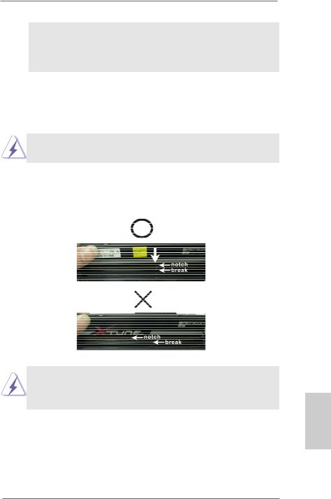
Installing a DIMM
Please make sure to disconnect the power supply before adding or removing DIMMs or system components.
Step 1. Unlock a DIMM slot by pressing the retaining clips outward. Step 2. Align a DIMM on the slot such that the notch on the DIMM
matches the break on the slot.
The DIMM only fits in one correct orientation. It will cause permanent damage to the motherboard and the DIMM if you force the DIMM into the slot at incorrect orientation.
Step 3. Firmly insert the DIMM into the slot until the retaining clips at both ends fully snap back in place and the DIMM is properly seated.
19
English
ASRock FM2A75 Pro4-M Motherboard

English
2.4 Expansion Slots (PCI and PCI Express Slots)
There is 1 PCI slot and 3 PCI Express slots on this motherboard.
PCI Slot: The PCI slot is used to install expansion cards that have 32-bit PCI interface.
PCIE Slots: PCIE1 (PCIE x16 slot) is used for PCI Express x16 lane width graphics cards, or used to install PCI Express graphics cards to support CrossFireXTM function.
PCIE2 (PCIE x1 slot) is used for PCI Express cards with x1 lane width. Such as Gigabit LAN card or SATA2 cards, etc.
PCIE3 (PCIE x16 slot) is used for PCI Express x4 lane width cards, or used to install PCI Express graphics cards to support CrossFireXTM function.
1.In single VGA card mode, it is recommended to install a PCI Express x16 graphics card on PCIE1 slot.
2.In CrossFireXTM mode, please install PCI Express x16 graphics cards on PCIE1 and PCIE3 slots.
Installing an expansion card
Step 1. Before installing the expansion card, please make sure that the power supply is switched off and the power cord is unplugged. Please read the documentation of the expansion card and make necessary hardware settings for the card before you start the installation.
Step 2. Remove the system unit cover (if your motherboard is already installed in a chassis).
Step 3. Remove the bracket facing the slot that you intend to use. Keep the screws for later use.
Step 4. Align the card connector with the slot and press firmly until the card is completely seated on the slot.
Step 5. Fasten the card to the chassis with screws. Step 6. Replace the system cover.
20
ASRock FM2A75 Pro4-M Motherboard
2.5 CrossFireXTM and Quad CrossFireXTM Operation Guide
This motherboard supports CrossFireXTM and Quad CrossFireXTM. CrossFireXTM technology offers the most advantageous means available of combining multiple high performance Graphics Processing Units (GPU) in a single PC. Combining a range of different operating modes with intelligent software design and an innovative interconnect mechanism, CrossFireXTM enables the highest possible level of performance and image quality in any 3D application. Currently CrossFireXTM feature is supported with Windows® XP with Service Pack 2 / VistaTM / 7 OS. Quad CrossFireXTM feature are supported with Windows® VistaTM / 7 OS only. Please check AMD website for AMD CrossFireXTM driver updates.
1.If a customer incorrectly configures their system they will not see the performance benefits of CrossFireXTM. All three CrossFireXTM components, a CrossFireXTM Ready graphics card, a CrossFireXTM Ready motherboard and a CrossFireXTM Edition co-processor graphics card, must be installed correctly to benefit from the CrossFireXTM multi-GPU platform.
2.If you pair a 12-pipe CrossFireXTM Edition card with a 16-pipe card, both cards will operate as 12-pipe cards while in CrossFireXTM mode.
2.5.1Graphics Card Setup
Different CrossFireXTM cards may require different methods to enable CrossFireXTM feature. For other CrossFireXTM cards that AMD has released or will release in the future, please refer to AMD graphics card manuals for detailed installation guide.
Step 1. Insert one Radeon graphics card into PCIE1 slot and the other Radeon graphics card to PCIE3 slot. Make sure that the cards are properly seated on the slots.
21
English
ASRock FM2A75 Pro4-M Motherboard
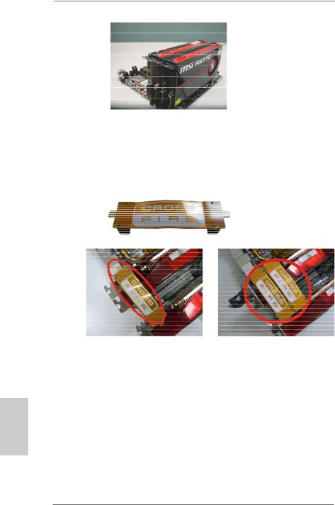
Step 2. Connect two Radeon graphics cards by installing a CrossFire Bridge on the top of the Radeon graphics cards. (The CrossFire Bridge is provided with the graphics card you purchase, not bundled with this motherboard. Please refer to your graphics card vendor for details.)
CrossFire Bridge
or
Step 3. Connect the DVI monitor cable to the DVI connector on the Radeon graphics card on PCIE1 slot. (You may use the DVI to D-Sub adapter to convert the DVI connector to D-Sub interface, and then connect the D-Sub monitor cable to the DVI to D-Sub adapter.)
English
22
ASRock FM2A75 Pro4-M Motherboard
2.5.2 Driver Installation and Setup
Step 1. Power on your computer and boot into OS.
Step 2. Remove the AMD driver if you have any VGA driver installed in your system.
The Catalyst Uninstaller is an optional download. We recommend using this utility to uninstall any previously installed Catalyst drivers prior to installation. Please check AMD’s website for AMD driver updates.
Step 3. Install the required drivers to your system.
For Windows® XP OS:
A.AMD recommends Windows® XP Service Pack 2 or higher to be installed (If you have Windows® XP Service Pack 2 or higher installed in your system, there is no need to download it again): http://www.microsoft.com/windowsxp/sp2/default.mspx
B.You must have Microsoft .NET Framework installed prior to downloading and installing the CATALYST Control Center. Please check Microsoft website for details.
For Windows® 7 / VistaTM OS:
Install the CATALYST Control Center. Please check AMD’s website for details.
Step 4. Restart your computer.
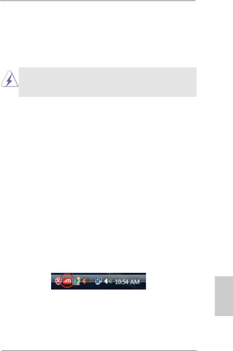
Step 5. Install the VGA card drivers to your system, and restart your computer. Then you will find “AMD Catalyst Control Center” on your
Windows® taskbar.
AMD Catalyst Control Center
Step 6. Double-click “AMD Catalyst Control Center”. Click “View”, select “CrossFireXTM”, and then check the item “Enable CrossFireXTM”. Select “2 GPUs” and click “Apply” (if you install two Radeon graphics cards).
23
English
ASRock FM2A75 Pro4-M Motherboard
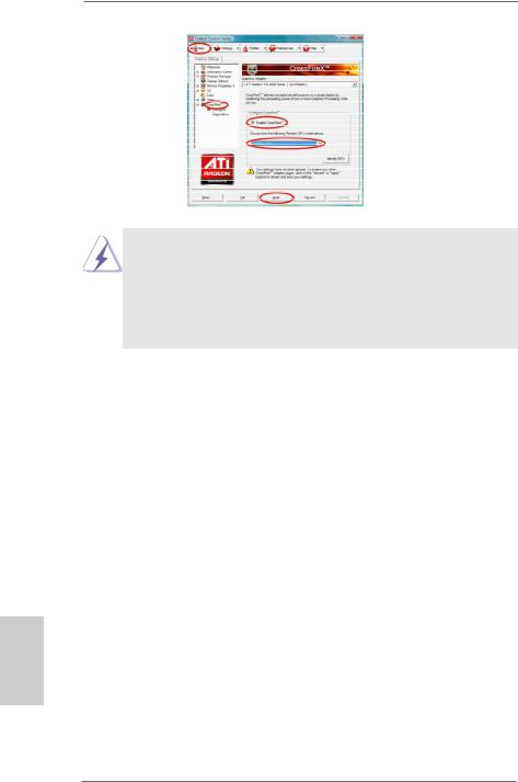
Although you have selected the option “Enable CrossFireTM”, the CrossFireXTM function may not work actually. Your computer will automatically reboot. After restarting your computer, please confirm whether the option
“Enable CrossFireTM” in “AMD Catalyst Control Center” is selected or not; if not, please select it again, and then you are able to enjoy the benefit of
CrossFireXTM feature.
Step 7. You can freely enjoy the benefit of CrossFireXTM or Quad CrossFireXTM feature.
*CrossFireXTM appearing here is a registered trademark of AMD Technologies Inc., and is used only for identification or explanation and to the owners’ benefit, without intent to infringe.
*For further information of AMD CrossFireXTM technology, please check AMD’s website for updates and details.
English
24
ASRock FM2A75 Pro4-M Motherboard
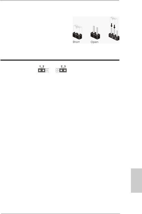
2.6 Jumpers Setup
The illustration shows how jumpers are setup. When the jumper cap is placed on pins, the jumper is “Short”. If no jumper cap is placed on pins, the jumper is “Open”. The illustration shows a 3-pin jumper whose pin1 and pin2 are “Short” when jumper cap is placed on these 2 pins.
Clear CMOS Jumper |
|
|
(CLRCMOS1) |
Default Clear CMOS |
|
(see p.2, No. 23) |
||
|
CLRCMOS1 allows you to clear the data in CMOS. To clear and reset the system parameters to default setup, please turn off the computer and
unplug the power cord from the power supply. After waiting for 15 seconds, use a jumper cap to short pin2 and pin3 on CLRCMOS1 for 5 seconds. However, please do not clear the CMOS right after you update the BIOS.
If you need to clear the CMOS when you just finish updating the BIOS, you must boot up the system first, and then shut it down before you do the clear-CMOS action. Please be noted that the password, date, time, user default profile, 1394 GUID and MAC address will be cleared only if the
CMOS battery is removed.
English
25
ASRock FM2A75 Pro4-M Motherboard

2.7 Onboard Headers and Connectors
Onboard headers and connectors are NOT jumpers. Do NOT place jumper caps over these headers and connectors. Placing jumper caps over the headers and connectors will cause permanent damage to the motherboard!
Serial ATA3 Connectors
(SATA3_1:
see p.2, No. 16) |
SATA3_5 SATA3_4 |
|
|
||
(SATA3_2: |
|
|
see p.2, No. 17) |
|
|
(SATA3_3: |
SATA3_3 SATA3_2 SATA3_1 |
|
see p.2, No. 18) |
||
|
||
(SATA3_4: |
|
|
see p.2, No. 15) |
|
|
(SATA3_5: |
|
|
see p.2, No. 14) |
|
These five Serial ATA3
(SATA3) connectors support SATA data cables for internal storage devices.
The current SATA3 interface allows up to 6.0 Gb/s data transfer rate.
Serial ATA (SATA) |
Either end of the SATA data |
Data Cable |
cable can be connected to |
(Optional) |
SATA / SATA2 / SATA3 hard |
|
disks or the SATA2 / SATA3 |
|
connectors on this mother- |
|
board. |
Print Port Header
(25-pin LPT1)
(see p.2, No. 27)
English
This is an interface for print port cables that allows convenient connection of printer devices.
26
ASRock FM2A75 Pro4-M Motherboard
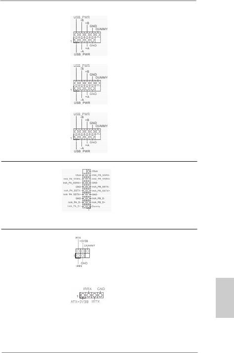
USB 2.0 Headers
and Ports
(9-pin USB5_6)
(see p.2, No. 22)
(9-pin USB7_8)
(see p.2, No. 24)
(9-pin USB9_10)
(see p.2, No. 26)
Besides four default USB 2.0 ports on the I/O panel, there are three USB 2.0 headers on this motherboard. Each USB 2.0 header can support two USB 2.0 ports.
USB 3.0 Header
(19-pin USB3_3_4)
(see p.2, No. 10)
Besides two default USB 3.0 ports on the I/O panel, there is one USB 3.0 header on this motherboard. Each USB 3.0 header can support two USB 3.0 ports.
Infrared Module Header |
|
This header supports an |
(5-pin IR1) |
|
optional wireless transmit- |
(see p.2, No. 29) |
|
ting and receiving infrared |
|
|
|
|
|
module. |
|
|
|
Consumer Infrared |
|
This header can be used |
Module Header |
|
t o c o n n e c t t h e r e m o t e |
(4-pin CIR1) |
|
controller receiver. |
|
||
(see p.2, No. 25) |
|
|
27
English
ASRock FM2A75 Pro4-M Motherboard

Front Panel Audio Header
(9-pin HD_AUDIO1)
(see p.2, No. 30)
This is an interface for the front panel audio cable that allows convenient connection and control of audio devices.
1.High Definition Audio supports Jack Sensing, but the panel wire on the chassis must support HDA to function correctly. Please follow the instructions in our manual and chassis manual to install your system.
2.If you use an AC’97 audio panel, please install it to the front panel audio header by the steps below:
A.Connect Mic_IN (MIC) to MIC2_L.
B.Connect Audio_R (RIN) to OUT2_R and Audio_L (LIN) to OUT2_L.
C.Connect Ground (GND) to Ground (GND).
D.MIC_RET and OUT_RET are for HD audio panel only. You don’t need to connect them for AC’97 audio panel.
E.To activate the front mic.
For Windows® XP OS:
Select “Mixer”. Select “Recorder”. Then click “FrontMic”.
For Windows® 7 / 7 64-bit / VistaTM / VistaTM 64-bit OS:
Go to the "FrontMic" Tab in the Realtek Control panel.
Adjust “Recording Volume”.
System Panel Header |
This header accommodates |
(9-pin PANEL1) |
several system front panel |
(see p.2, No. 21) |
functions. |
|
English
28
Connect the power switch, reset switch and system status indicator on the chassis to this header according to the pin assignments below. Note the positive and negative pins before connecting the cables.
ASRock FM2A75 Pro4-M Motherboard
PWRBTN (Power Switch):
Connect to the power switch on the chassis front panel. You may configure the way to turn off your system using the power switch.
RESET (Reset Switch):
Connect to the reset switch on the chassis front panel. Press the reset switch to restart the computer if the computer freezes and fails to perform a normal restart.
PLED (System Power LED):
Connect to the power status indicator on the chassis front panel. The LED is on when the system is operating. The LED keeps blinking when the sys-tem is in S1/S3 sleep state. The LED is off when the system is in S4 sleep state or powered off (S5).
HDLED (Hard Drive Activity LED):
Connect to the hard drive activity LED on the chassis front panel. The LED is on when the hard drive is reading or writing data.
The front panel design may differ by chassis. A front panel module mainly consists of power switch, reset switch, power LED, hard drive activity LED, speaker and etc. When connecting your chassis front panel module to this header, make sure the wire assignments and the pin assignments are matched correctly.
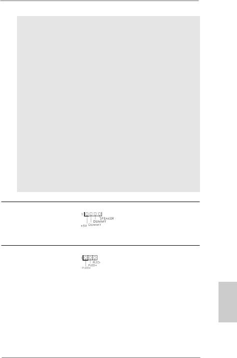
Chassis Speaker Header |
Please connect the chassis |
(4-pin SPEAKER1) |
speaker to this header. |
(see p.2, No. 19) |
|
Power LED Header
(3-pin PLED1)
(see p.2, No. 20)
Please connect the chassis power LED to this header to indicate system power status. The LED is on when the system is operating. The LED keeps blinking in S1 state. The LED is off in S3/ S4 state or S5 state (power off).
29
English
ASRock FM2A75 Pro4-M Motherboard
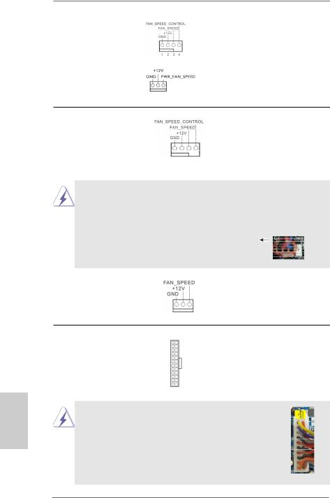
Chassis and Power
Fan Connectors
(4-pin CHA_FAN1)
(see p.2, No. 12)
(4-pin PWR_FAN1)
(see p.2, No. 1)
Please connect the fan cables to the fan connectors and match the black wire to the ground pin.
CPU Fan Connectors
(4-pin CPU_FAN1)
(see p.2, No. 5)
Please connect the CPU fan cable to the connector and match the black wire to the ground pin.
(3-pin CPU_FAN2)
(see p.2, No. 6)
English
ATX Power Connector |
12 |
24 |
Please connect an ATX pow- |
|
|
||
(24-pin ATXPWR1) |
|
|
er supply to this connector. |
(see p.2, No. 9) |
|
|
|
|
1 |
13 |
|
Though this motherboard provides a 24-pin ATX power connector, it can still work if you adopt a traditional 20-pin ATX power supply. To use a 20pin ATX power supply, please plug your power supply along Pin 1 and Pin 13.
20-Pin ATX Power Supply Installation
12 24
1 13
30
ASRock FM2A75 Pro4-M Motherboard
 Loading...