

Page 1
Service Source
Studio Display (17" CRT, 16"
VIS, ADC
11 March 2003
© 2003 Apple Computer, Inc. All rights reserved.
Page 2
Service Source
Take Apart
Studio Display (17" CRT, 16" VIS,
ADC)
© 2002 Apple Computer, Inc. All rights reserved.
Page 3
General Information
Safety Guidelines
Warning:
prevent serious injury, review CRT safety from the displays product area of
rollover links on Service Source online.
Warning:
setting up an ongoing ground connection.
Warning:
the EMI shield, board chassis, and other metal areas of the display assembly.
This product contains high voltage and a high-vacuum picture tube. To
Never use a grounding wriststrap until after discharging the CRT and
When the rear housing is removed, avoid the sharp sheet-metal edges of
General Information
Studio Display (17" ADC) Take Apart -
1
Page 4
Tools
The following tools are required:
• Soft, clean towel on which to place the display face down
• Hex driver, 3/32 inch
• #2 Phillips screwdriver
• #1 Phillips screwdriver
• CRT discharge tool (076-0392)
• Small, plastic, flat-blade screwdriver
• Needlenose pliers
• Jeweler’s screwdriver kit
Note:
To organize the screws your remove from the computer, use a tray with divided
compartments (such as a plastic ice cube tray).
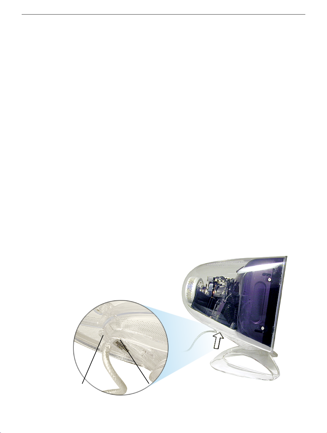
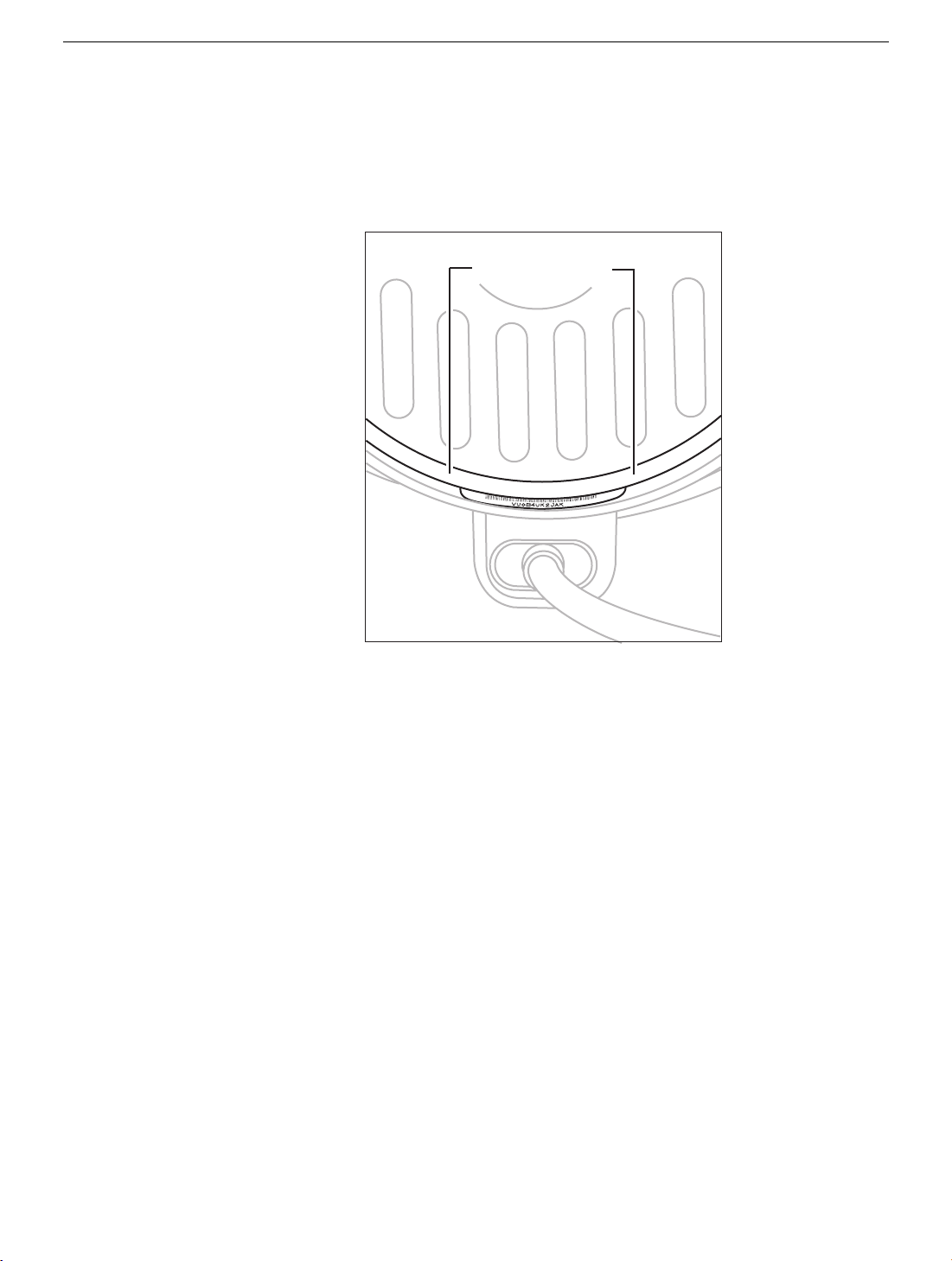
Serial Number Location
The serial number label on the Studio Display (17" CRT, 16" VIS, ADC) may be difficult to
locate. To locate the serial number label:
1. Swivel the monitor so the display is tilted down, and you are facing the side of the
monitor.
2. Position yourself so you are at eye level with the ADC cable exit point.
3. Locate the serial number label directly in front of the ADC cable exit point.
Exit Point
2 -
Studio Display (17" ADC) Take Apart
Serial Number LabelADC Cable
General Information
Page 5

Protecting the Translucent Housing
Important:
surface scratches can be more visible than on standard plastic housing. To avoid
cosmetic damage and protect the housing during service procedures, please keep
in mind the following precautions:
• Use a soft towel that is clean and free of debris whenever you service the
display.
• Use caution working with metal tools to avoid scratching the housing.
• Before placing the display face on a towel, ensure the surface provides
protection from scratches.
Because the housing of this monitor is made of translucent plastic,
General Information
Studio Display (17" ADC) Take Apart -
3
Page 6

Monitor Stand
Note:
The monitor stand is a customer-installable part and its replacement is covered by
the Customer Installable Parts (CIP) program. The following replacement procedure is
packed in-the-box with all replacement monitor stands.
Be sure to follow the instructions in this sheet carefully. Failure to follow these instructions
could result in damage to your equipment and may void your warranty.
Replacing your monitor stand requires five basic steps:
• Turn off the computer and disconnect the display cable.
• Place the monitor upside down on a thick cloth.
• Remove the monitor stand.
• Install the replacement monitor stand.
• Place the monitor upright, connect the display cable, and restart the computer.
Note:
Written and video instructions covering customer-installable parts are available at
http://www.info.apple.com/installparts/.
Tools
Two jeweler’s flat-blade screwdrivers are required for this procedure.
Note:
If you do not have jeweler’s screwdrivers, two long carpenter’s nails can be used.
However, the head of the nail must be at least 6 mm wide to prevent the nail from sliding
into the enclosure.
Warning: If any tools or parts drop into the monitor, do not turn on the monitor.
Contact Apple for further assistance. Never turn on your monitor unless all of its
internal and external parts are in place and it is closed. Operating the monitor when
it is open or missing parts can damage your monitor or cause injury.
Preliminary Steps
No preliminary steps are required before you begin this procedure.
4 -
Studio Display (17" ADC) Take Apart
Monitor Stand
Page 7
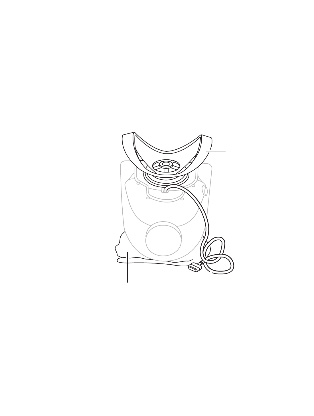
Removing the Monitor Stand
Monitor
Stand
Cloth
Display Cable
1. Warning: Turn off your computer and disconnect the display cable as follows:
• Unplug the display cable from the computer.
• Wait five minutes for the computer’s internal components to cool down.
2.
Warning:
monitor.
Use a thick, soft, clean cloth (such as a folded blanket or towel) as a cushion. Place
the monitor upside down on the cloth so the screen is away from you and the monitor
stand is in front of you.
3. Slide the monitor stand toward the display cable.
The monitor weighs 20 kg (45 pounds). Be careful when repositioning the
Monitor Stand
Studio Display (17" ADC) Take Apart -
5
Page 8
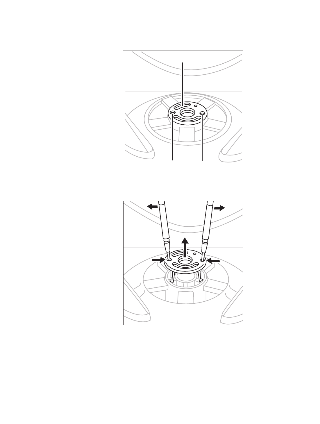
4. In the center of the monitor stand, locate the two identical round openings in the
Retaining Clip
Round Openings
retaining clip.
5. Using two jeweler’s flat-blade screwdrivers, place one in each of the round openings
and gently pry up the retaining clip until it is out of the monitor stand.
Warning: If any tools or parts drop into the monitor, do not turn on the monitor.
Contact Apple for further assistance. Never turn on your monitor unless all of
its internal and external parts are in place and it is closed. Operating the
monitor when it is open or missing parts can damage your monitor or cause
injury.
6 -
Studio Display (17" ADC) Take Apart
Monitor Stand
Page 9
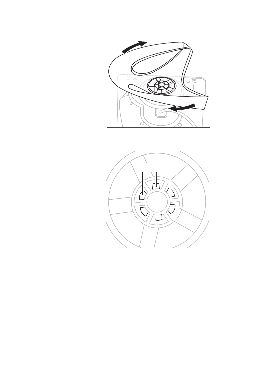
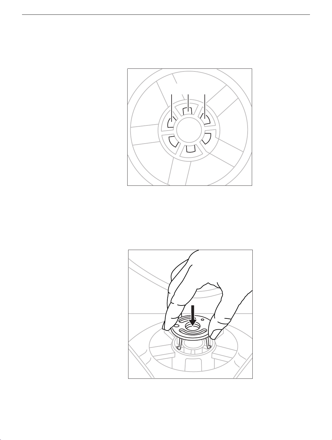
6. Rotate the stand clockwise (1/4 turn) so it is positioned as shown.
Locking Tabs
7. Peer into the center of the monitor stand and swivel it somewhat until you can see the
locking tabs line up with the slots in the base.
Monitor Stand
Studio Display (17" ADC) Take Apart -
7
Page 10
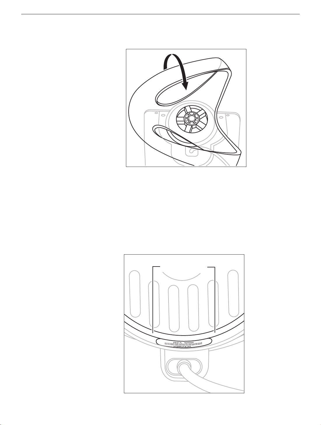
8. With the tabs aligned, gently pull the stand toward you. Then tilt the stand up off the
White Ring
Correctly Installed
base.
Positioning the Plastic Rings
After you remove the monitor stand, two plastic rings should remain on the base. These
rings are fitted in a special orientation so the replacement stand will fit properly. However,
if the rings are dislodged, replace them as follows:
1. Place the white plastic ring on the base so that you can still read the words "Serial
Number" when the ring is slid all the way down. Turn the ring over if the words are not
visible
8 -
Studio Display (17" ADC) Take Apart
Monitor Stand
Page 11
2. Place the clear plastic ring over the white ring so that the white ring fits inside the clear
Rings
Correctly Installed
ring.
3. Check that the rings are properly aligned. They should easily slide in unison, and
when they are close to the serial number label, you should be able to see the serial
number bar code but not be able to clearly see the words "Serial Number."
Monitor Stand
Studio Display (17" ADC) Take Apart -
9
Page 12
Installing the Replacement Monitor Stand
Locking Tabs
1. Holding the new monitor stand, align the slots in the center of the stand with the tabs
on the base of the monitor.
2. Slide the stand up to engage the locking tabs.
3. Turn the stand counterclockwise.
4. Align the retaining clip and press it down until it clicks into place. The retaining clip is
keyed and only fits one way.
5. Check that the stand slides easily.
6. Turn your monitor upright and reconnect it to the computer.
10 -
Studio Display (17" ADC) Take Apart
Monitor Stand
Page 13

7. Restart your computer.
Warning: Never turn on your monitor unless all of its internal and external parts
are in place and it is closed. Operating the monitor when it is open or missing
parts can damage your monitor or cause injury.
Apple Computer, Inc.
© 2001 Apple Computer, Inc. All rights reserved.
Under the copyright laws, this document ma y not be copied, in whole or in part, without the
written consent of Apple.
The Apple logo is a trademark of Apple Computer, Inc., registered in the U.S. and other
countries. Use of the “keyboard” Apple logo (Option-Shift-K) for commercial purposes
without the prior written consent of Apple may constitute trademark infringement and
unfair competition in violation of federal and state laws.
Every effort has been made to ensure that the information in this document is accurate.
Apple is not responsible for printing or clerical errors.
Apple Computer, Inc.
1 Infinite Loop
Cupertino, CA 95014-2084
408-996-1010
http://www.apple.com
Apple and the Apple logo are trademarks of Apple Computer, Inc., registered in the U.S.
and other countries.
Monitor Stand
Studio Display (17" ADC) Take Apart -
11
Page 14

Remove Rear Housing
Tools
The following tools are required:
• Hex driver, 3/32 inch
• Small, plastic, flat-blade screwdriver
• #1 Phillips screwdriver
• Needlenose pliers
• Jeweler’s screwdriver kit
Preliminary Steps
Before you begin, remove the monitor stand.
12 -
Studio Display (17" ADC) Take Apart
Remove Rear Housing
Page 15
Procedure
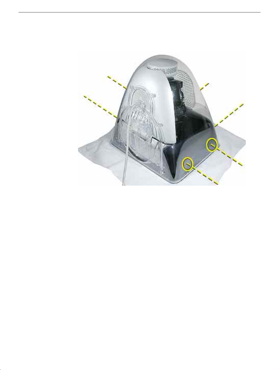
1. Remove six hex screws from the rear housing.
Remove Rear Housing
Studio Display (17" ADC) Take Apart -
13
Page 16
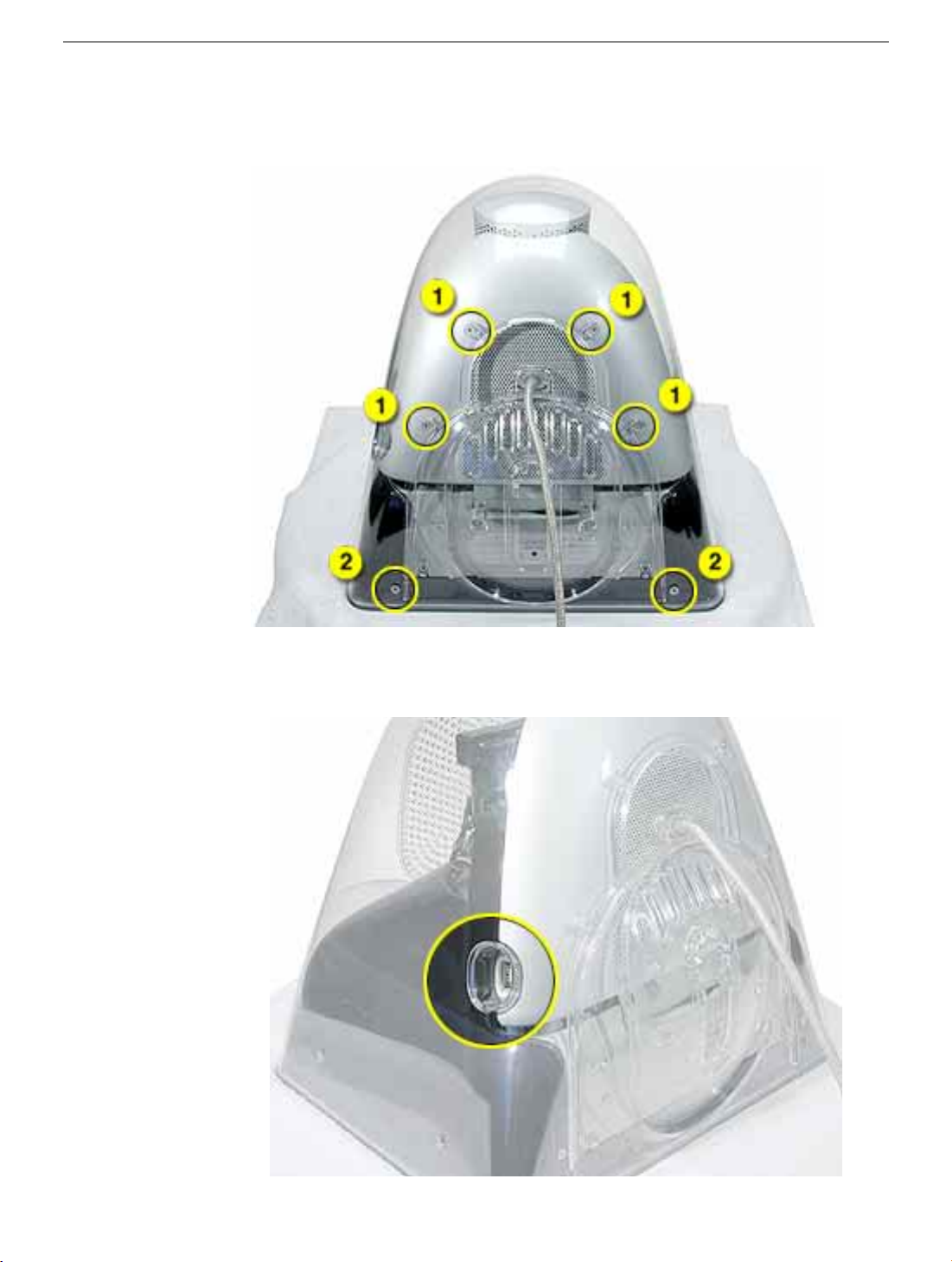
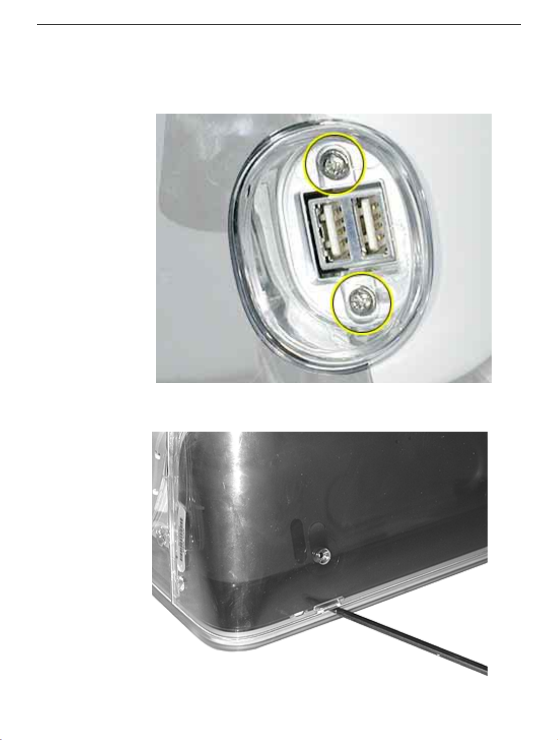
2. Remove four short hex screws (1) and two longer hex screws (2) from the rear of the
housing and the stand tilt base.
3. Locate the USB port. Use a small, plastic flat-blade screwdriver or needlenose pliers
to peel off the USB label.
14 -
Studio Display (17" ADC) Take Apart
Remove Rear Housing
Page 17
Replacement Note:
because the adhesive may not hold the label properly.
4. Remove two screws and the plastic USB hub (1) from the USB port.
Replace the USB label. The USB label should not be re-used
5. To remove the rear housing, use a plastic flat-blade screwdriver to push in locking
tabs at six locations around the bottom of the rear housing.
Remove Rear Housing
Studio Display (17" ADC) Take Apart -
15
Page 18
6. Lift off the rear housing.
Replacement Note:
side of the housing until you hear it snap securely onto the bezel.
When replacing the rear housing, push down firmly along each
16 -
Studio Display (17" ADC) Take Apart
Remove Rear Housing
Page 19

Remove CRT Shroud
Tools
The following tool is required:
• #2 Phillips screwdriver
Preliminary Steps
Before you begin, remove the following:
• Monitor stand
• Rear housing
Remove CRT Shroud
Studio Display (17" ADC) Take Apart -
17
Page 20

Procedure
1. Remove two screws from the CRT shroud.
2. Bow out slightly the bottom of the shroud and remove it from the CRT as shown.
18 -
Studio Display (17" ADC) Take Apart
Remove CRT Shroud
Page 21

Discharge the CRT and Remove Anode Cap
Tools
The following tools are required:
• CRT discharge tool (076-0392)
Preliminary Steps
Before you begin, remove the following:
• Monitor stand
• Rear housing
• CRT shroud
Discharge the CRT and Remove Anode Cap
Studio Display (17" ADC) Take Apart -
19
Page 22

Procedure
1. Attach the grounding clip of the CRT discharge tool to the metal frame of the CRT.
2. Insert the tip of the CRT discharge tool beneath the anode cap and make contact with
the edge of the anode (anode aperture).
20 -
Studio Display (17" ADC) Take Apart
Discharge the CRT and Remove Anode Cap
Page 23

3. Fold up the anode cap, then squeeze together the metal clip to remove it from the
internal edge of the anode aperture.
4. For working inside the monitor with the power off, establish an ongoing ground by
using a cable with alligator clips at both ends. Connect one end to the anode aperture,
and connect the other end to the metal CRT frame.
5. With the CRT discharged and the ongoing ground in place, wear a grounding
wriststrap to prevent equipment damage from static electricity.
Discharge the CRT and Remove Anode Cap
Studio Display (17" ADC) Take Apart -
21
Page 24

Replacement Note:
shown in the photo below.
When replacing the anode cable, secure it behind the tie wrap as
22 -
Studio Display (17" ADC) Take Apart
Discharge the CRT and Remove Anode Cap
Page 25

Deflection Board and Mount Assembly
Tools
The following tools are required:
• #2 Phillips screwdriver
• #1 Phillips screwdriver
• Small, plastic, flat-blade screwdriver
• Wire cutter
• Jeweler’s screwdriver
Preliminary Steps
Before you begin, remove the following:
• Monitor stand
• Rear housing
• CRT shroud
• Discharge the CRT
Deflection Board and Mount Assembly
Studio Display (17" ADC) Take Apart -
23
Page 26

Procedure
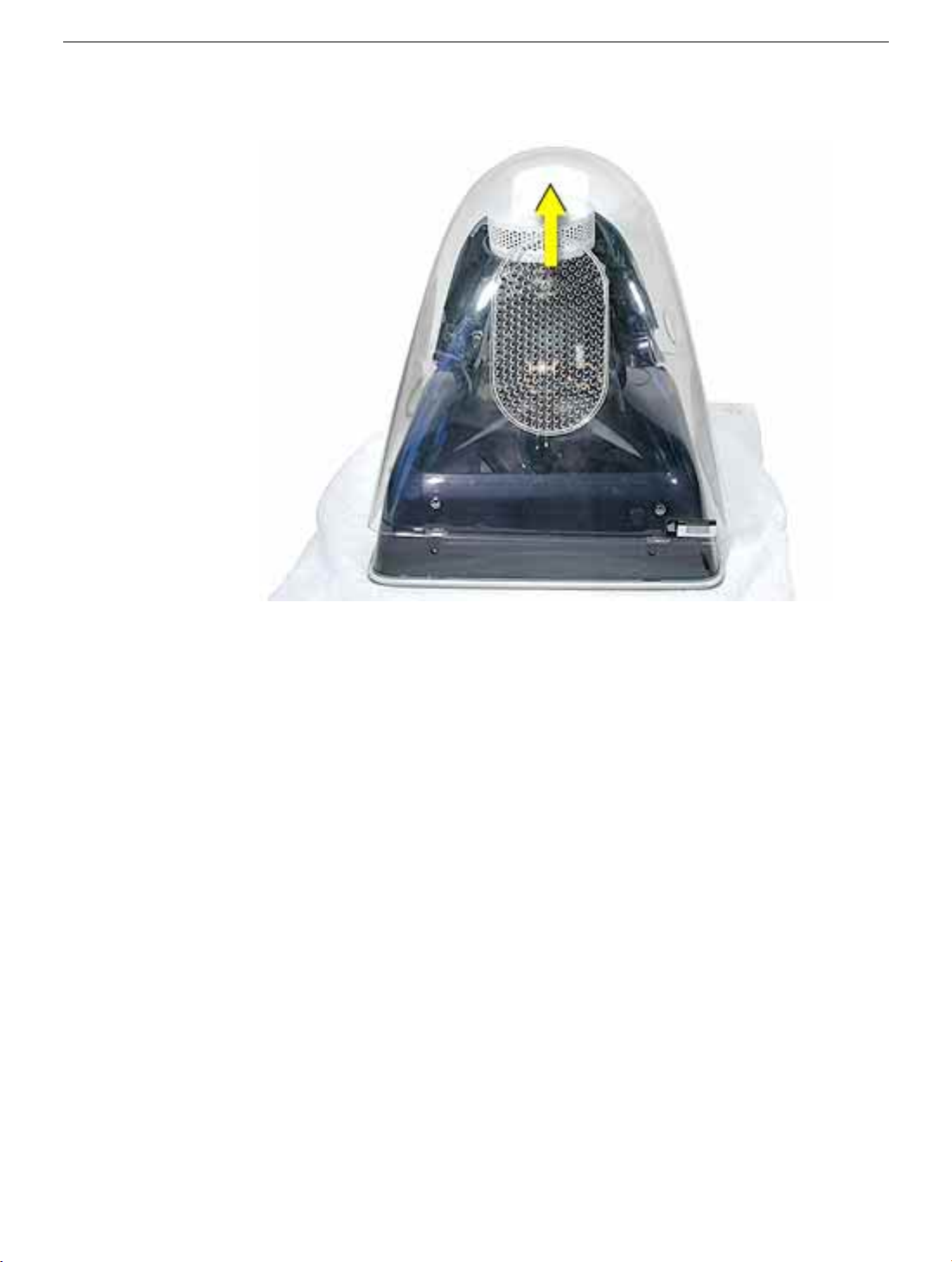
1. Using a jeweler's screwdriver, depress five plastic tabs while pulling up on the video
can. Separate the video can from the video shield.
2. Use #2 Phillips screwdriver to loosen the neck clamp as shown below.
24 -
Studio Display (17" ADC) Take Apart
Deflection Board and Mount Assembly
Page 27

3. Pull the video assembly straight up and off the neck of the CRT.
Replacement Note:
bent. Carefully align and position the video assembly connector on the neck of the
CRT before pressing it down firmly.
4. Remove four screws from the stand tilt base.
Visually inspect the pins on the CRT and straighten any that are
Deflection Board and Mount Assembly
Studio Display (17" ADC) Take Apart -
25
Page 28

5. Use wire cutters to cut four tie wraps. The three tie wraps on right side of CRT neck
are shown below; the fourth tie wrap is on the left side of the CRT neck.
6. Disconnect the degauss cable from deflection board connector B981.
26 -
Studio Display (17" ADC) Take Apart
Deflection Board and Mount Assembly
Page 29

7. Disconnect two anode cables from connectors at the rear of the CRT/yoke board.
8. Using a small, plastic flat-blade screwdriver, release two tabs at the top of the CRT/
yoke board cover and separate the cover from the CRT/yoke board.
Deflection Board and Mount Assembly
Studio Display (17" ADC) Take Apart -
27
Page 30

9. Remove two screws and four ground cables from the the video shield.
10. Tilt back the entire deflection/mount assembly f or better access in the following steps.
Disconnect the CRT ground cable (1) and the control board cable (2) from connector
B101.
28 -
Studio Display (17" ADC) Take Apart
Deflection Board and Mount Assembly
Page 31

11. Remove the deflection board and mount assembly from the CRT and place it on the
workbench.
Replacement Note:
CRT, place the edge of the stand tilt base in the bezel channel as shown below.
When replacing the deflection board and mount assembly on the
Deflection Board and Mount Assembly
Studio Display (17" ADC) Take Apart -
29
Page 32

Deflection Board Assembly
Tools
The following tools are required:
• #2 Phillips screwdriver
• #1 Phillips screwdriver
• Small, flat-blade screwdriver
• Jeweler’s screwdriver
• Needlenose pliers
Preliminary Steps
Before you begin, remove the following:
• Monitor stand
• Rear housing
• CRT shroud
• Discharge the CRT
• Deflection board and mount assembly
30 -
Studio Display (17" ADC) Take Apart
Deflection Board Assembly
Page 33

Procedure
1. Remove f our screws and tw o ground str aps from the deflection board and PCB mount.
Replacement Note:
a ground strap and clip to the lower, center mounting screw.
Attach ground straps to the outside mounting screws, and attach
Deflection Board Assembly
Studio Display (17" ADC) Take Apart -
31
Page 34

2. Disconnect these cables from the analog board:
• USB cable from connector B103
• LED cable from connector B105
• Ground cable from connector B901
3. Use flat-tip screwdriver to pry off the metal USB shield.
32 - Studio Display (17" ADC) Take Apart
Deflection Board Assembly
Page 35

4. Remove the six remaining screws from the analog board and PCB mount.
5. Remove the analog board from the PCB mount and place it nearby on the w orkbench.
Caution: Note that video cables still connect the anode board and PCB mount.
Deflection Board Assembly
Studio Display (17" ADC) Take Apart - 33
Page 36

6. Remove the screw and g round cab le from the bottom of the video shield. Remove two
of the remaining three screws as shown. Note: Do NO T remo ve the last scre w, shown
in red below.
7. Replacement Note: Note the position of the video cable and clip before performing
the next step. You may need a needlenose pliers to replace the video cable.
8. Disconnect the video cable from connector B708. Pull apart the video holder and
video shield enough to remove the video cable . Lace the video cable through the hole
at the bottom of the video shield.
34 - Studio Display (17" ADC) Take Apart
Deflection Board Assembly
Page 37

Video Cable
Tools
The following tools are required:
• #2 Phillips screwdriver
Preliminary Steps
Before you begin, remove the following:
• Monitor stand
• Rear housing
• CRT shroud
• Discharge the CRT
• Deflection board and mount assembly
• Deflection board assembly
Video Cable
Studio Display (17" ADC) Take Apart - 35
Page 38

Procedure
Replacement Note: Note the positioning of the video cables before removing them from
the PCB mount in the next step.
1. Remove four screws from the PCB mount, and remove the PCB mount (1) from the
bottom pan (2).
36 - Studio Display (17" ADC) Take Apart
Video Cable
Page 39

2. Turn over the bottom pan, and separate the stand tilt base (1) from the bottom pan.
3. Pull the video cable off the bottom pan and pop open the plastic strain reliefs.
Video Cable
Studio Display (17" ADC) Take Apart - 37
Page 40

4. Lace the video cables (1) through the bottom pan (2).
Note: Remov e fiv e clips from the video cab les bef ore returning a f aulty cable to Apple .
Note the position of the clips in the photo below.
38 - Studio Display (17" ADC) Take Apart
Video Cable
Page 41

CRT
Tools
The following tools are required:
• #2 Phillips screwdriver
• #1 Phillips screwdriver
Preliminary Steps
Before you begin, remove the following:
• Monitor stand
• Rear housing
• CRT shroud
• Discharge the CRT
• Deflection board and mount assembly
• Deflection board assembly
• Video cable
CRT
Studio Display (17" ADC) Take Apart - 39
Page 42

Procedure
1. Remove four screws (1) from the metal degauss frame. Remove four more (black)
screws (2) from bezel mount and degauss frame.
2. Lift slightly the bottom side of the degauss frame and disconnect the power button
cable and the launch button cable. Remove the CRT from the front bezel assembly.
40 - Studio Display (17" ADC) Take Apart
CRT
Page 43

Front Bezel
Tools
The following tools are required:
• #1 Phillips screwdriver
Preliminary Steps
Before you begin, remove the following:
• Monitor stand
• Rear housing
• CRT shroud
• Discharge the CRT
• Deflection board and mount assembly
• Deflection board assembly
• Video cable
• CRT
Front Bezel
Studio Display (17" ADC) Take Apart - 41
Page 44

Procedure
1. Use a small, plastic flat-blade screwdriver to disengage four plastic mounting tabs,
and pull up to separate the bezel mount from the front bezel.
2. Remove two screws and the power button board (1) from the front bezel.
42 - Studio Display (17" ADC) Take Apart
Front Bezel
Page 45

3. Remove two screws and the launch button board (2) from the bezel.
4. Remove the power button (1) and the launch button (2) from the front bezel.
Front Bezel
Studio Display (17" ADC) Take Apart - 43
Page 46

Service Source
Adjustments
Studio Display (17" CRT, 16" VIS,
ADC)
© 2002 Apple Computer, Inc. All rights reserved.
Page 47

Contents
Introduction ----------------- 2
Hardware Requirements ----------------- 2
Hardware Setup ----------------- 2
CA100 Equipment Setup ----------------- 3
Software Requirements ----------------- 3
Alignment Condition Requirements ----------------- 3
Alignment Procedures ----------------- 4
Turning ON the unit ----------------- 4
Data Upload ----------------- 4
Data Download ----------------- 4
B+ voltage check and adjustment ----------------- 4
USB output voltage check ----------------- 5
1V check and adjustment ----------------- 5
Raster centering ----------------- 5
Regulation check and adjustment ----------------- 5
CG check and adjustment ----------------- 5
Focus check and adjustment ----------------- 5
Beam Landing check and adjustment ----------------- 6
Geometry check and adjustment ----------------- 6
White balance check and adjustment ----------------- 6
VPT check and calibration ----------------- 8
EDID Data Check ----------------- 9
Theater Mode Check ----------------- 9
Bright Window Check ----------------- 9
Degauss Check ----------------- 10
Turning OFF the UUT ----------------- 10
APPENDIX A
Description of buttons functions in [Geometry] page 11
Description of buttons functions in [Color/Convergence] page 11
Description of menu functions 12
APPENDIX B
Wiring diagram for CA100 and 801GF to Mac serial port 14
Page 48

Introduction
RS232
USB
VGA
This is the read-me file for the documentation of the Mac-based Cabernet rework
(version 1.1) software. This documentation should be used in conjunction with the ADI
Cabernet service manual. Refer to the appendix A for descriptions on the available
software features and functions in this rework software.
Hardware Requirements
1. Power PC with PCI slot and serial ports.
2. ADS USB card.
3. Quantum 801GF with Mac serial cable connected to serial printer port.
4. Minolta CA100 with Mac serial cable connected to serial modem port.
5. 28V DC power brick with ADC to VGA/USB adapter board.
6. Multi-meter
7. Helmholtz cage.
8. Hand degausser.
9. Insulated alignment tools.
Hardware Setup
RS232
Minolta CA100
Power Brick
Mac CPU
801 GF
2
Page 49

CA100 Equipment Setup
1. Check that the CA100 has been set to FL.
2. Check that the baud rate has been set to 2400.
3. Connect the DB25 connector of the serial cable to the CA100 RS232 terminal and the
DIN 8 to the Mac serial modem port.
4. The Minolta color analyzer CA100 must be calibrated with a high accuracy
colorimeter (e.g. LMT) or photometer for the following color temperature in the
memory channels:
• Channel 1 = 4100.
• Channel 2 = 5000.
• Channel 3 = 6500.
• Channel 5 = 9300.
• Channel 6 = Red.
• Channel 7 = Green.
• Channel 8 = Blue.
Software Requirements
1. Mac OS 8.6 or above.
2. USB card support drivers version 1.1 drivers or above.
3. Apple monitors (version 2.0.3) - Tobiko software.
4. Apple Mac Cabernet rework software.
Alignment Condition Requirements
1. Unit-under-test (UUT) must be in burn-in with full white pattern (generated from
power brick when no external video signal is sensed) for a minimum of 30 minutes.
2. UUT must be properly degaussed before any alignment.
3. Alignment must be done in the helmholtz cage.
3
Page 50

Alignment Procedures
Turning ON the unit
1. Click on “Preset & read” to ensure that the Cabernet can be found on the USB.
Message should show “UUT found”, if not check the connection. Also ensure that the
check box “Preset Contrast” is ticked.
2. Click on the button “UUT ON” to power ON the UUT. Important note: Must click
on the button “UUT OFF” to power OFF the UUT after adjustment. Failure to click
“UUT OFF” will result in higher power consumption in sleep mode and abnormal
power ON operation (i.e. degauss activated before powering ON the Mac) when
connected to a Mac CPU.
Data Upload
1. Equipment: Mac with USB.
2. Condition:
(a) UUT must be able to communicate through the USB.
3. Select [Rework>Factory Data>Upload All] to upload the EEPROM contents from a
bad video board.
4. The EEPROM contents from the bad video will be stored in a factory data file format.
The EEPROM data in this file can be transferred to the new video board by using the
download function described next.
5. If the contents from the bad video board cannot be uploaded, then the alternative is to
use the factory backup files available at Apple’s ftp site for Cabernet. The address for
the ftp site will be made known later. Use the unit serial number to search for the
unit’s factory backup file.
Data Download
1. Equipment: Mac with USB.
2. Condition:
(a) UUT must be able to communicate through the USB.
3. Select [Rework>Factory Data>Download All] to download the EEPROM contents
from a video or a factory backup file to the new video board. Use this function to
reduce the amount of adjustment needed after a change of the video board .by
searching it using the UUT serial number.
4. Power OFF and ON the DC power supply to the UUT for the download EEPROM
data to take effect.
5. Check through all the adjustments against the specifications to ensure that the
downloaded EEPROM data work with the new video board.
6. Re-adjust when necessary.
B+ voltage check and adjustment
1. Equipment and adjustment procedure is the same as detailed in the service manual.
2. Condition:
(a) Timing mode is 1024x768@99Hz – select [Quantum Data>801 Formats>Cab 3 =
1024x768@99Hz]
(b) Pattern is White – select [Quantum Data>801 Patterns>White Page].
4
Page 51

USB output voltage check
1. Equipment and checking procedure is the same as detailed in the service manual.
1V check and adjustment
1. Equipment and adjustment procedure is the same as detailed in the service manual.
2. Condition:
(a) Timing mode is 1024x768@99Hz – select [Quantum Data>801 Formats>Cab 3 =
1024x768@99Hz]
(b) Pattern is Raster – select [Quantum Data>801 Patterns>Raster].
Raster centering
1. Equipment is the same as detailed in the service manual.
2. Condition:
(a) Timing mode is 1024x768@99Hz – select [Quantum Data>801 Formats>Cab 3 =
1024x768@99Hz]
(b) Pattern is Green Frame – select [Quantum Data>801 Patterns>Green Frame].
3. In the color and convergence page, set the G cutoff to maximum at 0xFF to see the
edge of the raster.
4. Adjustment procedure is the same as detailed in the service manual.
Regulation check and adjustment
1. Equipment and checking procedure is the same as detailed in the service manual.
2. Condition:
(a) Timing mode is 1024x768@99Hz – select [Quantum Data>801 Formats>Cab 3 =
1024x768@99Hz]
(b) Pattern is “Regulate” – select [Quantum Data>801 Patterns>Regulate].
3. Adjustment – use the “H EHT Comp” and “V EHT Comp” scroll bars in the color
and convergence page to adjust the regulation.
CG check and adjustment
1. Equipment and adjustment procedure is the same as detailed in the service manual.
2. Condition:
(a) Timing mode is 1024x768@99Hz – select [Quantum Data>801 Formats>Cab 3 =
1024x768@99Hz]
(b) Pattern is X-Hatch White – select [Quantum Data>801 Patterns>X-Hatch White]. Use
the RGB buttons on the 801GF for manual control over the color displayed.
(c) Ensure that the H/V static controls are at the default position 0x7F.
Focus check and adjustment
1. Equipment and adjustment procedure is the same as detailed in the service manual.
2. Condition:
(a) Timing mode is 1280x1024@75Hz – select [Quantum Data>801 Formats>Cab 3 =
1280x1024@75Hz]
(b) Pattern is Focus – select [Quantum Data>801 Patterns>Focus]+ [Quantum Data>801
Controls>Reverse]. After adjustment do [Quantum Data>801 Controls>Reverse].
5
Page 52

Beam Landing check and adjustment
1. Equipment and adjustment procedure is the same as detailed in the service manual.
2. Condition:
(a) Timing mode is 1024x768@99Hz – select [Quantum Data>801 Formats>Cab 3 =
1024x768@99Hz]
(b) Pattern is Green Page – select [Quantum Data>801 Patterns>Green page].
Note: Prior to any alignment of the beam landing the UUT must be warm-up in a full
white page at 15fl.
Geometry check and adjustment
1. Equipment and adjustment procedure is the same as detailed in the service manual.
2. Condition:
(a) Timing mode is all the seven timing formats from Cab_1 to Cab_7.
(b) Pattern is Green Frame – select [Quantum Data>801 Patterns>Green Frame].
3. If the geometry data was downloaded from the factory file or the original video
board, check that the geometry for the 7 timing formats is within specifications. If not
then start the geometry adjustment.
4. Adjustment – start with prime mode at timing Cab_3 format. Note: Mode
independent parameters are in black in the Geometry page. Blue indicates mode
dependent parameters – these must be aligned and checked at the different timing
formats from Cab_1 to Cab_7. Do a “Read All” whenever there is a change of timing
format, so as to get the actual parameter settings.
5. When geometry is within specifications in the Cab_3 format, click “Save user” then
click “Do Prediction”. Prediction function is used to cut down the adjustment time for
the rest of the timing formats. It is OK to skip the prediction function and proceed to
the adjustment for next timing format, but just remember to click “Save user” before
changing the timing format.
6. Check the geometry from timing formats Cab_1 to Cab_7 and touch-up if necessary.
For formats that are within specifications click on “Save user” for each mode before
changing the timing format.
7. When all the 7 timing formats are checked to be within specifications, click on “Save
defaults” to save the settings into the factory EEPROM space.
White balance check and adjustment
1. Equipment: calibrated CA100.
2. Condition:
(a) Timing mode is 1024x768@99Hz – select [Quantum Data>801 Formats>Cab 3 =
1024x768@99Hz]
(b) Pattern for cutoff adjustment is GrayScale 16 – select [Quantum Data>801
Patterns>X-GrayScale 16].
(c) Pattern for white balance adjustment is VPT Page – select [Quantum Data>801
Patterns>VPT Page].
(d) Make sure the contrast is set at maximum 0x60.
6
Page 53

3. Cutoff adjustment
Target
y = green
x = red
x = blue
y = blue, x = red.
(a) Set the pattern to “GrayScale 16”.
(b) Check that the cutoff is at 2nd bar just slightly visible. If not then start the cutoff
adjustment. Note: For better judgement of the 2nd bar use the reverse setting by
selecting [Quantum Data>801 Controls>Reverse].
(c) Adjustment - In the color page, click on “Preset Color”.
(d) Use the scroll bar “RGB Cutoff” to adjust until the second gray bar just disappear or
barely visible. Note: The “RGB Cutoff” control is a pseudo cutoff scroll bar control
to ease the adjustment of R, G, B cutoff controls together – actual steps change will
be reflected in the individual R, G, B cutoff scroll bars.
4. White balance check
(a) Set the pattern to “VPT Page”.
(b) Place and hold the CA100 probe in the center of the white page.
(c) If the white balance data was downloaded from the factory file or the original video
board, a check must be performed to ensure that the white balance is within high
brightness specifications (contrast at max 0x60) of x = 283±10, y = 298±10, Y=
33±3, and low brightness specifications (adjust contrast to achieve Y= 2.5±1 FL) of x
= 283±10, y = 298±10.
(d) If white balance is not within specifications then perform the manual or auto white
balance procedures.
5. Manual white balance alignment
(e) Set the pattern to “VPT Page”.
(f) Place and hold the CA100 probe in the center of the white page.
(g) Adjust the contrast to achieve about 2.5±1fl.
(h) Measure the low light color to determine whether the CRT is red, green or blue bias.
Use the biasing template shown below to judge the biasing. CIE specifications for this
product is at x = 283, y = 298.
y - target > x - target then
y = blue
x - target > y - target then
x = blue, y = green.
x = red
y = green
7
Page 54

(i) With the CRT biasing determined, do not touch the cutoff for that color.
(j) Use only two of the cutoffs that are indicated by the CRT color biasing template for
the adjustment until the low color is within specs. If there is difficulty in getting the
low color within specifications then move to high brightness color adjustment.
(k) Specifications for the white balance adjustment is at 9300 - x = 283±5, y = 298±5, Y=
33±1
(l) Set the contrast to maximum at 0x60.
(m) For high light color adjustment use R Drive for CIE x adjustments, G Drive for CIE y
adjustments. For brightness adjustment, use the R, G, B Drives and adjust them
together.
(n) Adjust the contrast to achieve about 2.5±1fl.
(o) Check and adjust the low light color until it is within the specification.
(p) Repeat steps (j) to (p) until the high and low color is within specifications.
(q) To save the color settings click on the “Save” button.
5. Auto white balance alignment
(a) Set the pattern to “VPT Page”.
(b) Initialize the CA100 by selecting [Minolta>Setup>Initialize CA100].
(c) Check that the remote light on the CA100 is lighted.
(d) To zero calibrate the probe select [Minolta>Setup>Zero Calibrate Probe].
(e) Place and hold the CA100 probe in the center of the white page.
(f) Select [Rework>White Balance>X-Align White Balance].
(g) When the white balance adjustment pass, the message shown is: “ Passed white
balance adjustment”.
VPT check and calibration
1. Equipment: calibrated CA100.
2. Condition:
(a) Timing mode is 1024x768@99Hz – select [Quantum Data>801 Formats>Cab 3 =
1024x768@99Hz].
(b) Pattern is “VPT Page” – select [Quantum Data>801 Patterns>VPT Page].
(c) Make sure the contrast is set at maximum 0x60.
3. VPT calibration check
(a) If the VPT data is downloaded from the factory file or original video board then
Select [Rework>VPT Tests>Check Calibration].
(b) Select memory channel 5 of CA100 to measure 9300.
(c) Take the reading of the CA100 and compare with the reading display from the
software.
(d) Pass the VPT calibration if the difference between the measured and calculated x, y
readings are within ± 5 units (e.g. if CA100 measured x = 285 and y = 300 and the
calculated x = 283, y = 298 then the VPT calibration check is a pass). If it failed then
performed the VPT calibration process described next.
8
Page 55

4. VPT calibration
(a) Select [Rework>VPT Tests>Download Constants].
(b) Check that CA100 is initialized and the remote light is ON.
(c) Select [Rework>VPT Tests>Perform VPT Characterization].
(d) When the calibration pass, the message shown is: “Color and VPT tests passed!”.
EDID Data Check
1. Equipment: Mac with USB.
2. Condition:
(a) Ensure that the UUT has completed VPT check or calibration process.
3. Select [Rework>EDID>Download Default Constants].
4. Select [Rework>EDID>Copy Magic Cookie].
5. Select [Rework>VPT Tests>Get Magic Cookie]. Note down the magic cookie
number.
6. Select [Rework>EDID>Get EDID ID]. Ensure that the EDID ID number is the same
as the magic cookie number.
Theater Mode Check
1. Equipment: Mac with USB, CA100, Quantum Data 801GF.
2. Condition:
(a) Completed white balance adjustment.
3. Select [Quantum Data>801 Patterns>5 Boxes]. Note: Make sure the background is
black, if not just choose reverse option to set the background black.
4. Measure the brightness for the center box – say Y1 fl
5. In the color page click on the button “Bright Win ON”. Button should change to
“Bright Win OFF”, which means the next click on the button will turn Bright
Window mode OFF.
6. In the color page click on the button “Full Screen ON”. Button should change to “Full
Screen OFF”, which means the next click on the button will turn Full Screen mode
OFF.
7. Measure the brightness for the center box again – say Y2 fl
8. Pass the UUT if the Y2/Y1 brightness ratio is at least 1.4 times.
9. Click on the buttons to turn off the full screen mode first then the bright window
mode.
Note: The “Vert Blnk DC” scroll bar should be at 0x8C and the “Delta DC Level” scroll
bar should be at 0x03.
Bright Window Check
1. Equipment: Mac with USB, CA100, Quantum Data 801GF.
2. Condition: Completed white balance adjustment
(a) Completed white balance adjustment.
3. Select [Quantum Data>801 Patterns>Bright Window]. Note: Make sure the
background is black, if not just choose reverse option to set the background black.
4. Measure the brightness for the center box – say Y1 fl
5. In the color page click on the button “Bright Win ON”.
9
Page 56

6. Measure the brightness for the center box again – say Y2 fl
7. Pass the UUT if the Y2/Y1 brightness ratio is at least 1.4 times.
8. Turn off the bright window mode.
Note1: The “Vert Blnk DC” scroll bar should be at 0x8C and the “Delta DC Level” scroll
bar should be at 0x03.
Note2: If the bright window mode did not work, check that the length of the video cable
is not too long to cause any double image or power ON/OFF the DC power brick and try
again.
Degauss Check
1. Equipment: Hand degausser.
2. Condition:
(a) Timing format can be any of Cab_1 to Cab_7.
(b) Pattern is “Red Page” – select [Quantum Data>801 Patterns>Red Page].
3. Magnetize the UUT using the hand degausser by press/ release shortly to magnetize
the UUT at about 10cm away in the center of the screen. Screen should have some R,
G, B color patches.
4. Click on the “Degauss” button. The UUT internal degauss should be activated and the
screen should be just red without any color patches.
5. If the color patches remain then the degauss function is not working.
Turning OFF the UUT
When the UUT passes all the adjustments, click on the button “UUT OFF” and the UUT
will just shutdown. Important note: Must click on the button “UUT OFF” to power
OFF the UUT after adjustment. Failure to click “UUT OFF” will result in higher power
consumption in sleep mode and abnormal power ON operation (i.e. degauss activated
before powering ON the Mac) when connected to a Mac CPU.
10
Page 57

APPENDIX A
Description of buttons functions in [Geometry] page
1. Preset & read – Preset default (max) Contrast setting and read the parameters values.
2. UUT ON/OFF – Turn ON or OFF the unit. If button shows “UUT OFF” it means that
hitting the button “UUT OFF” will turn OFF the unit. Vice versa for “UUT ON”.
Note: UUT means “Unit-Under-Test”.
3. Load defaults – Load the factory aligned values.
4. Read ALL – Read all the alignment parameters values in the current page.
5. Degauss – Activate the built-in degauss function.
6. Save user – Save the current page’s parameters values into the user EEPROM.
7. Timing – Read what is the current vertical timing frequency of cab1, cab2,….
8. Save defaults – Save the current page’s parameters values into the factory EEPROM.
9. Do Prediction – Predict the other geometry modes parameters based on the alignment
data stored in the Cab_3 timing (1024x768@99Hz prime mode) user EEPROM.
Predicted values for the other timing mode parameters will be stored in the user
EEPROM.
10. Degauss State – Check on the power ON degauss state – i.e. whether power ON
degauss is enabled. Must be enabled.
11. File -> EE – Downloads the file contents (in simple text file format of [address data])
to the EEPROM.
12. EE -> file – Uploads the EEPROM data and stores the data in simple text file format.
Use the check boxes [IVAD Data] or [VPT Data] to select the kind of upload data.
Description of buttons functions in [Color/Convergence] page
Note: Some buttons functions are the same as previous.
1. Save – Save all the current parameters values into user and factory EEPROM.
2. Preset Color – Set the R, G, B drives and cutoffs prior to cutoff and color alignment.
3. Get HiIks – Read the R, G, B high beam currents.
4. Get LoIks – Read the R, G, B low beam currents.
5. Bright Win ON/OFF – Activate/de-activate the bright window feature.
6. Full Screen ON/OFF – Activate/de-activate the theater mode feature. Must be used
with bright window mode ON.
11
Page 58

Description of menu functions
PROGRAM
1. “Program>Quit” – To quit the program.
Rework/ Get UUT Info
1. “Rework > Get UUT Info > ID number”- shows the production process ID number.
2. “Rework > Get UUT Info > Manufacture date”- shows the unit’s production date.
This is created in production during the VPT calibration process.
3. “Rework > Get UUT Info > Service date”- shows the unit’s service date. This is
created whenever there is any save to the UUT’s EEPROM.
Rework/ VPT Tests
1. “Rework > VPT Tests > Download Constants”- Downloads the VPT constants.
2. “Rework > VPT Tests > Check VPT calibration”- Check on the correctness of the
VPT calibration using calculation based on the RGB characterization data. To be used
with a white pattern setting.
3. “Rework > VPT Tests > Get Checksum Data”- To check if the RGB characterization
data in the EEPROM is correct
4. “Rework > VPT Tests > Get Max RGB Ik”- Show what are the max RGB beam
currents stored in the VPT EEPROM.
5. “Rework > VPT Tests > Get Magic cookie”- Show what is the unit’s unique ID. This
unique ID must matched the unique ID stored in the EDID data.
6. “Rework > VPT Tests > Get Coulomb Counter”- Show what is the amount of aging
the CRT has gone through. This is updated at about every 35mins interval.
7. “Rework > VPT Tests > Zero Coulomb Counter”- Reset the aging counters. Used
only when set is serviced and it is also automatically zeroed during the VPT
calibration process.
8. “Rework > VPT Tests > Perform VPT characterization”- Perform VPT calibration
using a serially controlled CA100.
Rework/ White Balance
1. “Rework > White Balance > Align White Balance”- Perform the white balance
adjustment using a serially controlled CA100.
Rework/ EDID
1. “Rework > EDID> Download Default Constants”- Downloads the default EDID
constants.
2. “Rework > EDID> Copy Magic Cookie”- Copy the magic cookie number from VPT
EEPROM to EDID data EEPROM.
3. “Rework > EDID> Get EDID ID”- Shows the magic cookie number that is stored in
the EDID EEPROM. Must be the same as the number shown in the “Get Magic
Cookie”.
4. “Rework > EDID> Upload EDID To File”- Uploads the EDID data and stores the
data in simple text file format.
12
Page 59

Rework/ Factory Data
1. “Rework > Factory Data > Upload All”- Uploads all the whole UUT EEPROM data
and stores the data in the factory file format. Can be used to backup EEPROM data
prior to changing of video board to minimize re-alignment
2. “Rework > Factory Data > Download All”- Downloads all the data stored in a valid
factory file format and writes the data into the UUT EEPROM. Can be used during
the repair process to transfer the UUT data into a new video board.
3. “Rework > Factory Data > Convert to Excel format”- Converts a UUT factory backup
file to a excel readable format.
4. “Rework > Factory Data > Convert to Excel format”- Converts a UUT factory backup
file to a simple text readable format.
Quantum Data
1. “Quantum Data > 801 Formats >”- For serial control of the Quantum 801timing
modes/ formats.
2. “Quantum Data > 801 Patterns >”- For serial control of the Quantum 801 patterns.
3. “Quantum Data > 801 Controls >”- For serial control of the Quantum 801 controls.
Minolta
1. “Minolta> Setup >”- For serial control of the CA100. Initialization and zero probe
should be performed prior to the software white balance adjustment functions and
VPT calibration functions.
2. “Minolta > Channel >”- For serial control of the CA100 channel selection.
13
Page 60

APPENDIX B
8763452123547
RxD+
RxD-
TxD-
TxD
RxD
GND
RTS
CTS
Shield GND
Male DIN 8
CA100 DB25
876345212
385
RxD+
RxD-
TxD-
TxD
RxD
GND
RTS
CTS
Shield GND
Male DIN 8
801 DB9
Wiring diagram for CA100 and 801GF to Mac serial port
14
 Loading...