


 Loading...
OPERATING INSTRUCTIONS
Protect C
Protect C.1000
Protect C.2000
Protect C.3000
EN
2
3
Thank you for purchasing the AEG UPS PROTECT C from AEG Power Solutions.
Safety information and operating instructions are included in this manual. To ensure correct use of the UPS, please read this manual thoroughly before operating it. Use this manual properly.
4
CONTENT
1. |
Notes on these Operating Instructions .................. |
6 |
||
2. |
General Information................................................... |
8 |
||
|
2.1 |
Technology ................................................................... |
8 |
|
|
2.2 |
System Description ....................................................... |
9 |
|
|
2.3 |
Technical information.................................................. |
11 |
|
3. |
Safety |
........................................................................ |
16 |
|
|
3.1 |
General Safety Instructions......................................... |
16 |
|
|
3.2 |
Safety .................................Instructions for Protect C |
17 |
|
|
3.3 |
CE ..............................................................-Certificate |
20 |
|
4. |
Set-Up ..............................................and Operation |
21 |
||
|
4.1 |
Unpacking ...........................................and Inspection |
21 |
|
|
4.2 |
Point ......................................................of Installation |
22 |
|
5. |
Overview Connections, Operating / Display |
|
||
|
Elements ................................................................... |
23 |
||
|
5.1 |
Front ...................................................................View |
23 |
|
|
5.2 |
Rear ............................................View (Connections) |
24 |
|
6. |
Commissioning ........................................................ |
26 |
||
|
6.1 |
Mechanical ......................................................Set-Up |
26 |
|
|
6.2 |
External ..........................................Battery Extension |
27 |
|
|
6.3 |
Power ..............................................................Supply |
28 |
|
|
6.4 |
Consumer ................................................Connection |
29 |
|
7. |
Operation ...............................................and usage |
31 |
||
|
7.1 |
Initial .........................................................Installation |
31 |
|
|
7.1.1 ............................................... |
Switching on UPS |
31 |
|
|
7.1.2 ............................................... |
Switching off UPS |
31 |
|
|
7.2 |
Control ..............................................................Panel |
32 |
|
|
7.2.1 ............................................................. |
Overview |
32 |
|
|
7.2.2 ................................................ |
Indicators (LEDs) |
32 |
|
|
7.2.3 ........................................ |
Operating (Navigation) |
33 |
|
|
7.3 |
Display ...................................................(Main Menu) |
34 |
|
|
7.3.1 ............................................. |
UPS Status Display |
34 |
|
|
7.3.2 ............................................................ |
Event Log |
38 |
|
|
7.3.3 .................................................... |
Measurements |
39 |
|
5
|
7.3.4 |
Control ................................................................ |
39 |
|
|
7.3.5 |
Identification........................................................ |
40 |
|
|
7.3.6 |
Settings ............................................................... |
41 |
|
8. |
Interfaces and communication............................... |
46 |
||
|
8.1 |
RS232 and USB Computer Interfaces ........................ |
46 |
|
|
8.2 |
Communication slot .................................................... |
46 |
|
|
8.3 |
Shutdownund UPS Management Software ............. |
47 |
|
|
8.4 |
EPO (Emergency Power Off)...................................... |
48 |
|
9. |
Trouble Shooting ..................................................... |
49 |
||
|
9.1 |
Malfunctions................................................................ |
49 |
|
|
9.1.1 |
Alarm- / Error messages ..................................... |
49 |
|
10.Maintenance ............................................................. |
54 |
|||
|
10.1 |
Battery Charging ......................................................... |
54 |
|
|
10.2 |
Maintenance ............................................................... |
54 |
|
|
10.2.1 Visual Check ....................................................... |
54 |
||
|
10.2.2 Checking the Battery........................................... |
55 |
||
|
10.2.3 Fan Checking...................................................... |
55 |
||
|
10.3 |
Battery replacement.................................................... |
55 |
|
11.Storage, Dismantling and Disposal ....................... |
57 |
|||
|
11.1 |
Storage ....................................................................... |
57 |
|
|
11.2 |
Dismantling ................................................................. |
57 |
|
|
11.3 |
Disposal ...................................................................... |
57 |
|
12.Glossary.................................................................... |
59 |
|||
|
12.1 |
Technical Terms ......................................................... |
59 |
|
|
12.2 |
Key Word Register...................................................... |
61 |
|
6
1.NOTES ON THESE OPERATING INSTRUCTIONS
DUTY TO PROVIDE INFORMATION
These operating instructions will help you to install and operate the Uninterruptible Power Supply (UPS) PROTECT C.1000, PROTECT C.2000 or PROTECT C.3000 as well as the associated external battery units PROTECT C.1000 BP or PROTECT C.2030 BP – all referred to as PROTECT C in this document – safely and properly, and for its intended purpose. These operating instructions contain important information necessary to avoid dangers during operation. Please read these instructions carefully prior to commissioning!
THESE OPERATING INSTRUCTIONS ARE A COMPLETE PART OF THE PROTECT C
The owner of this unit is obliged to communicate the full content of these operating instructions to all personnel transporting or starting the PROTECT C or performing maintenance or any other work on the unit.
VALIDITY
These operating instructions comply with the current technical specifications of the PROTECT C at the time of delivery. The contents do not constitute a subject matter of the contract, but serve for information purposes only.
WARRANTY AND LIABILITY
We reserve the right to alter any specifications given in these operating instructions, especially with regard to technical data and operation, prior to start-up or as a result of service work. Claims in connection with supplied goods must be submitted within one week of receipt, along with the packing slip. Subsequent claims cannot be considered.
The warranty does not apply to damage caused by non-compliance with these instructions (such damage also includes damaging the warranty seal). AEG will accept no liability for consequential damage. AEG reserves the right to rescind all obligations such as warranty agreements, service contracts, etc. entered into by AEG and its representatives without prior notification in the event of maintenance and repair work being carried out with anything other than original AEG spare parts or spare parts purchased by AEG.
7
HANDLING
PROTECT C is designed and constructed so that all necessary steps for start-up and operation can be performed without any internal manipulation of the unit. Maintenance and repair work may only be performed by trained and qualified personnel.
Illustrations are provided to clarify and facilitate certain steps.
If danger to personnel and the unit cannot be ruled out in the case of certain work, it is highlighted accordingly by pictograms explained in chapter 3.
HOTLINE
If you still have questions after having read these operating instructions, please contact your dealer or our “Hotline”:
Tel: |
+49 2902 763100 |
Internet: |
www.aegps.com |
COPYRIGHT
No part of these operating instructions may be transmitted, reproduced and/or copied by any electronic or mechanical means without the express prior written permission of AEG.
© Copyright AEG 2014. All rights reserved.
8
2. GENERAL INFORMATION
2.1TECHNOLOGY
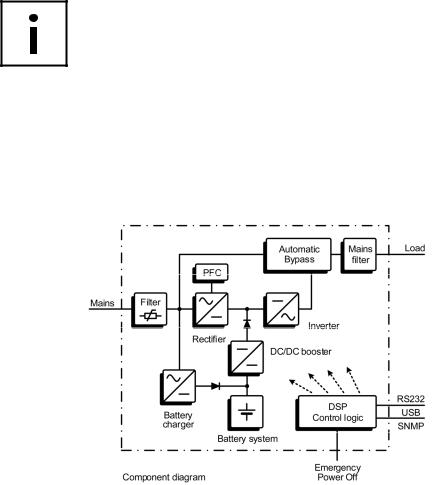
PROTECT C is an Uninterruptible Power Supply (UPS) for essential loads such as PCs, workstations, servers, network components, telecommunication equipment and similar devices. It consists of:
Mains filter with surge voltage protection (device protection/ class D) and mains energy backfeed protection
Rectifier section with PFC logic (power factor correction unit)
Separate battery charger with switch mode power supply technology
Sealed, maintenance-free battery system as energy storage medium with downstream DC/DC converter unit
IGBT inverter for continuous supply of connected loads with sinusoidal AC voltage
Automatic bypass as additional passive redundancy
Control unit based on digital signal processor technology
9
2.2SYSTEM DESCRIPTION
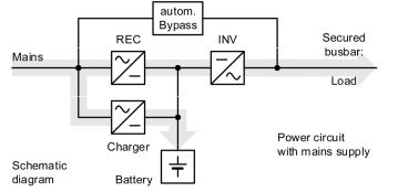
The UPS is connected to a shockproof socket between the public utility’s mains and the loads to be protected.
The power section of the rectifier converts the mains voltage to DC voltage for supplying the inverter. The circuit technology used (PFC) enables sinusoidal current consumption and therefore operation with little system disturbance. A separate, second rectifier (charging REC set up using switch mode power supply technology) is responsible for charging or trickle-charging the battery connected in the intermediate circuit. The configuration of this charging REC means the harmonic content of the charging current for the battery is almost zero, so the service life of the battery is increased even more. The inverter is responsible for converting the DC voltage into a sinusoidal output voltage. A microprocessor-controlled control system based on pulsewidth modulation (PWM) in conjunction with an extremely quickly pulsating IGBT power semiconductors of the inverter guarantee that the voltage system on the protected busbar is of the highest quality and availability.
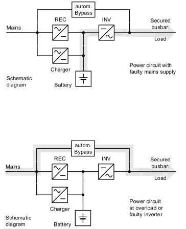
In the event of mains faults (e.g. power outage), the voltage continues to be supplied from the inverter to the load without any interruption. From this point onwards, the inverter draws its power from the battery instead of the rectifier. No switching operations are necessary; this means there is no interruption in the supply to the load.
10
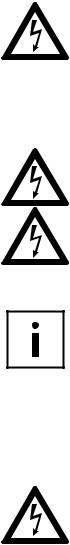
The automatic bypass serves to increase the reliability of the supply further. It switches the public mains directly through to the load if there is an inverter malfunction. As a result, the automatic bypass represents an extra passive redundancy for the load.
The graphical LC display used provides for versatile use and easy operation. Such a convenient feature as an emergency power off contact round out the standard interface selection (USB, RS232, communication slot).
11
2.3TECHNICAL INFORMATION
Power rating
Protect C.1000 |
1000 VA (cos φ = 0.8 lag.) 800 W |
|
|
|
|
Protect C.2000 |
2000 VA (cos φ = 0.8 lag.) 1600 W |
|
|
|
|
Protect C.3000 |
3000 VA (cos φ = 0.8 lag.) 2400 W |
|
|
|
|
UPS Input |
1ph~ / N / PE |
|
Rated input voltage |
200 / 208 / 220 / 230 / 240 VAC |
|
Rectifier voltage range |
|
|
(without battery |
176 – 300 VAC |
|
operation, 100 % load, |
||
|
||
cos = 0.8 lag.) |
|
|
Rectifier voltage range |
|
|
(without battery operation, |
110 – 300 VAC |
|
50 % load, cos = 0.8 lag.) |
|
|
Nominal frequency |
50 Hz / 60 Hz |
|
(autom. detection or manual) |
||
|
||
Frequency tolerance |
±10 % |
|
Power consumption at full load (max.) |
||
Protect C.1000 |
4.8 / 4.6 / 4.4 A |
|
|
UN = 220 / 230 / 240 VAC |
|
Protect C.2000 |
8.9 / 8.5 / 8.2 A |
|
|
UN = 220 / 230 / 240 VAC |
|
Protect C.3000 |
13.1 / 12.5 / 12.0 A |
|
|
UN = 220 / 230 / 240 VAC |
|
Bypass voltage range |
176 VAC – 264 VAC |
|
Mains feedback factor |
≥0.99 (THDi <5 %) |
|
Connection |
IEC connector |
|
UPS Output |
|
|
Rated output voltage |
200 / 208 / 220 / 230 / 240 VAC ±2 % |
|
|
Power reduction at 200 VAC 20 % / |
|
|
at 208 VAC 10 % |
|
Nominal frequency |
50 Hz / 60 Hz ±0.2 Hz |
|
|
(Tolerance in battery mode or free running |
|
|
in variable-frequency inverter mode) |
|
Synchronization range |
50 Hz / 60 Hz ±10 % |
|
Synchronization speed |
1 Hz/s |
|
12
Power factor range |
0.3 lag. to 0.9 cap. |
|
||
|
at full output |
|
|
|
|
Power reduction of 20 % to 0.5 cap. |
|||
Inverter frequency |
40 % power reduction |
|
||
|
(Bypass disabled, Input Frequency Range |
|||
|
40 - 70 Hz) |
|
|
|
Sinus waveform |
Sinus waveform distortion |
|
||
|
<3 % THD (linear load) |
|
||
|
<5 % THD (non-linear load) |
|
||
Connection |
IEC sockets |
|
|
|
Crest factor |
3:1 |
|
|
|
Overload behaviour |
up to 105 % continuous; |
|
||
|
>105 % – <110 % for 60 s; |
|
||
|
≥110 % – <125 % for 30 s; |
|
||
|
≥125 % – |
150 % for 10 s; |
|
|
|
Then automatic inverter to Bypass |
|||
|
in < 4 ms (switches back when |
|||
|
overload damps = Load < 90%) |
|||
|
|
|
||
Overload bypass |
Up to 125 % continuous |
|
||
|
>125 % – 150 % 10 min. |
|
||
Short circuit |
3 x IN for 100 ms |
|
||
Battery |
|
|
|
|
Autonomy Time |
|
|
|
|
External |
cos = 0.8 lag. / 100 % charged battery |
|||
battery module |
|
|
|
|
C.1000 |
C.2000 |
C.3000 |
||
|
||||
With integrated battery |
4.5 min. |
7 min. |
3.5 min. |
|
1 add. battery module |
25 min. |
38,5 min. |
21 min. |
|
2 add. battery modules |
51 min. |
70 min. |
45 min. |
|
Battery check |
daily; weekly; monthly |
|
||
(programmable) |
|
|
|
|
Rated DC voltage (intermediate circuit) |
|
|
||
Protect C.1000 |
36 VDC |
|
|
|
Protect C.2000 |
96 VDC |
|
|
|
Protect C.3000 |
96 VDC |
|
|
|
Battery charging current |
1 ADC |
|
(max.) |
||
|

13
Battery type |
sealed maintenance free (VRLA) |
|
|
Protect C.1000 |
12 V 7 Ah x 3 |
|
Protect C.2000 |
12 V 7 Ah x 8 |
|
Protect C.3000 |
12 V 7 Ah x 8 |
|
Protect C.1000 BP |
12 V 7 Ah x 3 x 2 |
|
Protect C.2030 BP |
12 V 7 Ah x 8 x 2 |
Recharge time (to 90 % |
~ 8 h (UPS with internal battery) |
|
of rated capacity) |
~ 24 h (with 1 additional battery) |
|
|
~ 40 h (with 2 additional batteries) |
|
Communication |
|
|
Interfaces |
RS232 SUB-D (9-pin), USB |
|
|
Additional: communication slot for |
|
|
Extensions (eg, relay card, SNMP (Pro), ...) |
|
Remote shutdown contact Potential-free (optionally programmable as
|
opener or closer) |
|
Shutdown Software |
“CompuWatch” for all popular operating |
|
on CD |
systems like:. Windows, Linux, |
|
|
Mac, Unix, Novell, Sun |
|
General data |
|
|
Classification |
VFI SS 111 acc. to. IEC 62040–3 |
|
|
double conversion technology (INV / BATT) |
|
|
VFI SS 311 acc. to IEC 62040–3 |
|
|
ECO mode |
|
Full load efficiency |
Protect C.1000 |
≥87 % / ≥85 % |
(AC-AC / DC-AC) |
Protect C.2000 |
≥88 % / ≥85 % |
|
Protect C.3000 |
≥88 % / ≥85 % |
Full load efficiency |
Protect C.1000 |
≥93 % |
(ECO / Transfer time |
Protect C.2000 |
≥94 % |
<10 ms) (economical |
Protect C.3000 |
≥94 % |
mode) |
|
|
Inherent noise |
Protect C.1000 |
≤44 dB (A) |
(1 m distance) |
Protect C.2000 |
≤49 dB (A) |
|
Protect C.3000 |
≤49 dB (A) |
Type of cooling |
Forced cooling by variable speed fans |
|
Operating temperature |
0 °C to 45 °C Recommendation +15 °C |
|
|
to +25 °C (due to battery system) |
|
Storage temperature |
-15 °C to +60 °C (UPS) |
|
|
0 °C to +35 °C (Battery) |
|

14
Humidity |
0 – 95 % (non-condensing) |
|
|
|||
Max. site altitude |
Up to 1000 m rated power |
|
|
|
||
|
Usage >1000 m above sea |
|
|
|||
|
level results in a derating as follows: |
|
||||
|
Height (m) |
1000 |
1500 |
2000 |
2500 |
3000 |
|
Power (%) |
100 |
95 |
90 |
85 |
80 |
Protection |
IP20 |
|
|
|
|
|
Outlets |
Protect C.1000 |
4 x IEC 320 C13 |
||||
|
Protect C.2000 |
6 x IEC 320 C13 |
||||
|
Protect C.3000 |
4 x IEC 320 C13 |
||||
|
|
|
+1 x IEC 320 C19 |
|||
|
|
|
+1 fixed connection on |
|||
|
|
|
terminal block |
|
||
Display |
Graphic LCD, resolution: 128 x 64 pixels |
|||||
|
Languages: DE / EN / ES / FR / RU |
|
||||
|
3 LEDs for power indication |
|
|
|||
Equipment color |
Blackline |
|
|
|
|
|
Weight |
|
|
(net / gross) |
|
||
|
Protect C.1000 |
13 kg / 15 kg |
|
|||
|
Protect C.1000 BP |
18 kg / 19 kg |
|
|||
|
Protect C.2000 |
31 kg / 33 kg |
|
|||
|
Protect C.3000 |
31 kg / 33 kg |
|
|||
|
Protect C.2030 BP |
44 kg / 46 kg |
|
|||
Dimensions |
Protect C.1000 |
145 mm x 220 mm |
||||
W x H x D (net) |
|
|
x 400 mm |
|
||
|
Protect C.1000 BP |
145 mm x 220 mm |
||||
|
|
|
x 400 mm |
|
||
|
Protect C.2000 |
192 mm x 347 mm |
||||
|
|
|
x 460 mm |
|
||
|
Protect C.3000 |
192 mm x 347 mm |
||||
|
|
|
x 460 mm |
|
||
|
Protect C.2030 BP |
192 mm x 347 mm |
||||
|
|
|
x 460 mm |
|
||

15
Dimensions
W x H x D (gross) (packaging)
Protect C.1000 |
240 mm x 330 mm |
|
x 495 mm |
Protect C.1000 BP |
300 mm x 330 mm |
|
x 500 mm |
Protect C.2000 |
330 mm x 475 mm |
|
x 590 mm |
Protect C.3000 |
330 mm x 475 mm |
|
x 590 mm |
Protect C.2030 BP |
330 mm x 475 mm |
|
x 590 mm |
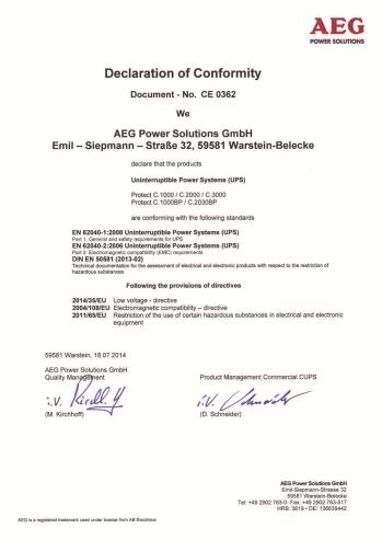
Guidelines |
The PROTECT D complies with the |
|
EN 62040 product standard. |
|
The CE seal on the device confirms that the |
|
device complies with the following directives: |
|
EG Low Voltage Directive 2014 / 35 / EU as |
|
well as the EMC Directive 2004 / 108 / EG for |
|
electromagnetic compatibility, if the |
|
installation instructions provided in this |
|
manual are followed. |
|
For 2014 / 35 / EU Low Voltage Directive |
|
Reference number |
|
EN 62040-1: 2008 |
|
For 2004 / 108 / EG EMC-Directive |
|
Reference number |
|
EN 62040-2: 2006 Class C1 |

16
3. SAFETY
3.1GENERAL SAFETY INSTRUCTIONS
Read these operating instructions prior to start-up of the PROTECT C UPS and its external battery modules (special accessories), and observe the safety instructions.
Only use the unit if it is in a technically perfect condition and always in accordance with its intended purpose, while being aware of safety and danger aspects, and in accordance with the operating instructions!
Immediately eliminate any faults that could be detrimental to safety. The following pictograms are used in these operating instructions to identify dangers and important information:
Danger!
Identifies risk of fatal injury to the operator.
Attention!
Identifies risk of injury and risk of damage to the unit and parts of the unit.
Information!
Useful and important hints for the operation of the UPS and its external battery modules (special accessories).

17
3.2SAFETY INSTRUCTIONS FOR PROTECT C
This chapter contains important instructions for the PROTECT C UPS and its external battery modules (special accessories). These must be followed during assembly, operation and maintenance of the uninterruptible power supply and the battery systems (internal and, if appropriate, external as well).
The UPS carries high voltage. Danger! The unit may only be opened by trained and qualified personnel. Repairs may only be carried out by qualified customer service staff!
The output may be live, even if the UPS is not connected to the mains, since the UPS has its own internal power supply (battery)!
The equipment must be properly earthed in order to protect personnell!
PROTECT C may only be operated with or connected to a 220 V / 230 V / 240 V mains with protective grounding using a CE marked mains connection cable with PE conductor (included in the delivery) that has been tested in accordance with national standards.
Danger! Risk of burning!
The battery has powerful short-circuit currents. Incorrect connection or isolation faults can lead to melting of the plug connections, sparking potential and severe burns!
The unit has a warning signal that sounds when the battery voltage of PROTECT C is exhausted or when the UPS is not working in its normal mode (see also chapter 9.1.1, Page 49).

18
Observe the following safety instructions to ensure permanent operational safety of and safe work with the UPS and the battery modules (special accessories):
Do not dismantle the UPS!
(The UPS does not contain any parts that require regular maintenance. Bear in mind that the warranty will be invalidated if the unit is opened!)
Do not install the unit in direct sunshine or in close proximity of heaters!
The unit is designed to be installed inside in heated rooms. Never install the housing in the vicinity of water or in an excessively damp environment!
Condensation may occur if the UPS is brought from a cold environment into the room where it is to be installed. The UPS must be absolutely dry prior to start-up. As a result, leave it to acclimatise for at least two hours.
Never connect the mains input to the UPS output, and vice versa!
Ensure that no fluids or foreign bodies can penetrate the housing!
Do not block the air vents of the unit! Keep children away from the unit and ensure that objects are never inserted through the air vents!
Do not connect household appliances such as hairdryers to the UPS! Also take care when working with motor loads. It is essential to avoid back-feeding the inverter, e.g. if the load is intermittently operated in regenerative mode.
The mains connection should be near the unit and easily accessible to facilitate disconnecting the AC input or pulling out the plug!
During operation, do not disconnect the mains connection cable from the UPS or from the socket outlet in the building (shockproof socket), otherwise the protective grounding of the UPS and all the loads connected to it will be cancelled.
Danger! Electric shocks!
Even after the mains voltage has been disconnected, the components within the UPS remain connected to the battery and can thus cause electric shocks. It is therefore imperative to disconnect the battery circuit before carrying out any maintenance or repair work!
If it is necessary to replace the battery or carry out maintenance work, this must be done by or under the supervision of a specialist familiar with batteries and the necessary safety precautions!
19
Only authorised persons are allowed in the vicinity of the batteries! When replacing the batteries, the following must be observed:
Only ever use identical maintenance-free sealed lead batteries with the same data as the original batteries.
Only authorised persons are allowed in the vicinity of the batteries!
When replacing the batteries, the following must be observed:
Only ever use identical maintenance-free sealed lead batteries with the same data as the original batteries.
Danger! Explosive!
Never throw batteries into open fire. Never open or damage batteries. (Electrolyte may leak out and damage skin and eyes. It may be toxic!)
Batteries can cause electric shocks and high short-circuit currents.
Take the following safety precautions when working with the batteries:
Take off watches, rings and other metallic objects!
Always use tools with insulated handles!
Do not switch loads on and off using the UPS main switch. Do not use multiple outlet adapters with a central on/off switch, in order to avoid peak inrush currents.
Switch OFF the UPS if you do not intend to use it for some time. PROTECT C must be switched off every evening if the electricity supply in your company is switched off every night. Otherwise, the battery will be discharged (assumed power failure). Frequent and complete discharging of the battery leads to a shorter service life of the battery and should therefore be avoided!
For personal safety reasons, never switch on the main switch when the mains connector of PROTECT C is disconnected!
20
3.3CE-CERTIFICATE
Loading...