


PRODUCTDOCUMENTATION
PROTECT PV.630
Solarinverter
EN

Operating instructions
Installation and Start-up
Maintenance and Servicing
Single-line Diagram
Outline Drawing
Connection Diagram
Technical Data Sheet
Operating instructions
Protect PV.630
AEG Power Solutions GmbH, Warstein-Belecke
Department: |
PS AED |
Revision: |
00 |
Revision date: |
23.01.2013 / Schenuit |
Released: |
23.01.2013 / Wäsche |
Document no. |
8000047961 BAL, en |

Protect PV.630 Operating Instructions
|
AEG Power Solutions GmbH |
|
Emil-Siepmann-Strasse 32 |
|
59581 Warstein |
|
Germany |
|
+49 2902 763 100 |
Fax: |
+49 2902 763 645 |
e-mail: |
service.aegpss@aegps.com |
Internet: |
http://www.aegps.com |
2 of 72 |
8000047961 BAL |

Protect PV.630 Operating Instructions
Table of Contents
1 |
Information on How to Use these Instructions............... |
6 |
1.1 |
General Information............................................................. |
6 |
1.2 |
Target Groups ..................................................................... |
7 |
1.3 |
Explanations of Target Groups............................................ |
7 |
1.3.1 |
Obligations of the Equipment Operator ............................... |
7 |
1.3.2 |
Skilled Personnel Skills and Trainings ................................ |
8 |
1.4 |
Storing Instructions.............................................................. |
9 |
2 |
Explanation of Symbols and Safety Instructions......... |
10 |
2.1 |
Explanation of Symbols..................................................... |
10 |
2.2 |
Safety Instructions............................................................. |
11 |
2.2.1 |
Signal Words Used............................................................ |
11 |
2.2.2 |
Hazard Symbols Used....................................................... |
11 |
2.2.3 |
Signs Containing Orders for Personal Protective |
|
|
Equipment ......................................................................... |
12 |
2.2.4 |
Abbreviations..................................................................... |
13 |
2.3 |
Emergency Procedure (e.g. in the Event of a Fire) ........... |
13 |
2.4 |
Safety Awareness ............................................................. |
13 |
2.5Particular Dangers associated with Photovoltaic Systems14
2.6 |
Safety Signs and Warning Notices on the Equipment....... |
15 |
2.7 |
Safety and Protection Devices for the Equipment............. |
15 |
2.7.1 |
Protective Covers .............................................................. |
15 |
2.7.2 |
Lockable Equipment Doors ............................................... |
16 |
2.7.3 |
Guard ................................................................................ |
16 |
2.8 |
Residual Hazards .............................................................. |
16 |
2.8.1 |
Electrical Hazards ............................................................. |
17 |
2.8.2 |
Risks Due to Moving Parts ................................................ |
18 |
2.8.3 |
Fire-Related Risks............................................................. |
18 |
2.8.4 |
Risks due to Loss of Control ............................................. |
19 |
2.8.5 |
Risks from Maintenance and Repair Work........................ |
19 |
3 |
Product Details ................................................................ |
20 |
3.1 |
Product Description ........................................................... |
20 |
3.2 |
Dimensions and Views ...................................................... |
21 |
3.3 |
Appropriate Use ................................................................ |
21 |
3.4 |
Inappropriate Use.............................................................. |
22 |
3.5 |
Standards, Directives and CE Mark .................................. |
22 |
3.6 |
Nameplate ......................................................................... |
22 |
3.7 |
Technology........................................................................ |
23 |
3.8 |
Operating Elements........................................................... |
24 |
4 |
System Description......................................................... |
25 |
4.1 |
Operating Modes............................................................... |
25 |
4.1.1 |
Individual Operation .......................................................... |
25 |
4.1.2 |
Partner Operation.............................................................. |
25 |
8000047961 BAL |
3 of 72 |

Protect PV.630 Operating Instructions
5 |
System Function ............................................................. |
26 |
5.1 |
Description of Sequence Control....................................... |
26 |
5.1.1 |
The “OFF” Status .............................................................. |
26 |
5.1.2 |
The “Waiting for Feed Conditions” Status ......................... |
26 |
5.1.3 |
The “Operation” Status...................................................... |
27 |
5.1.4 |
The “Waiting” Status.......................................................... |
27 |
5.1.5 |
The “Fault” Status.............................................................. |
28 |
5.1.6 |
The “Night” Status ............................................................. |
28 |
5.1.7 |
Sequence Control During the Course of the Day .............. |
28 |
5.1.8 |
Sequence Control Parameters .......................................... |
30 |
5.2 |
Description of Fan Control................................................. |
31 |
5.2.1 |
General.............................................................................. |
31 |
5.2.2 |
Fan Control, Cabinet Fan .................................................. |
31 |
5.2.3 |
Cabinet Fan Control Parameters....................................... |
32 |
5.2.4 |
Fan Control, Inverter Stack Fan ........................................ |
32 |
5.2.5 |
Parameters of Inverter Stack Fan Control......................... |
33 |
5.3 |
Insulation Monitoring and Earthing of PV Cells ................. |
33 |
5.3.1 |
General.............................................................................. |
33 |
5.3.2 |
Operation With Monocrystalline or Polycrystalline Solar |
|
|
Cells .................................................................................. |
34 |
5.3.3 |
Operation with Thin-Film Solar Cells................................. |
34 |
5.3.4 |
Insulation Monitoring in Partner Operation........................ |
35 |
5.3.5 |
Insulation Monitoring Parameters...................................... |
35 |
5.4 |
MPP Tracker ..................................................................... |
36 |
5.5 |
Partner Operation.............................................................. |
36 |
5.5.1 |
Linked Operation ............................................................... |
36 |
5.5.2 |
Single Operation................................................................ |
37 |
5.5.3 |
Linked Operation in the Event of a Fault ........................... |
38 |
5.5.4 |
Partner Operation During the Course of the Day .............. |
38 |
5.5.5 |
Partner Operation Parameters .......................................... |
39 |
5.6 |
“Extended” operating mode............................................... |
39 |
5.6.1 |
Parameters of the “Extended” operating mode ................. |
40 |
6 |
Monitoring Systems, Messages and Faults.................. |
40 |
6.1 |
General.............................................................................. |
40 |
6.2 |
Table of Faults................................................................... |
42 |
4 of 72 |
8000047961 BAL |

Protect PV.630 Operating Instructions |
|
|
7 |
Interfaces ......................................................................... |
46 |
7.1 |
Communication Interface .................................................. |
46 |
7.1.1 |
General.............................................................................. |
46 |
7.1.2 |
Technical Data .................................................................. |
47 |
7.1.3 |
Structure of the MultiCom CCC Interface......................... |
48 |
7.1.4 |
Configuration ..................................................................... |
52 |
7.1.4.1 Configuration Preparations................................................ |
52 |
|
7.1.4.2 Configuring the Modbus Protocol ...................................... |
54 |
|
7.1.4.3 Configuring Modbus Data Transmission ........................... |
55 |
|
7.2 |
COM Server ...................................................................... |
56 |
7.2.1 |
General.............................................................................. |
56 |
7.2.2 |
Network Connection .......................................................... |
56 |
7.2.3 |
Structure of the COM Server............................................. |
56 |
7.2.4 |
Installation of the COM Server .......................................... |
57 |
7.2.5 |
Network Integration Configuration..................................... |
58 |
7.2.6 |
Configuration of the Virtual COM Port............................... |
58 |
7.3 |
Remote Signalling ............................................................. |
59 |
8 |
Graphical Display and Operation Unit........................... |
61 |
8.1 |
General.............................................................................. |
61 |
8.1.1 |
Signalling........................................................................... |
62 |
8.1.2 |
Keyboard Operation .......................................................... |
62 |
8.2 |
Start-up.............................................................................. |
63 |
8.3 |
Menu Structure.................................................................. |
64 |
8.3.1 |
Menu Tree ......................................................................... |
64 |
8.3.2 |
Main Menu......................................................................... |
64 |
8.3.3 |
Operating Display.............................................................. |
65 |
8.3.4 |
Status/Measured Values ................................................... |
70 |
8.3.5 |
Blocking............................................................................. |
71 |
8.3.6 Fault History......................................................................... |
72 |
|
8.3.7 |
Settings ............................................................................. |
72 |
8.3.8 |
Information ........................................................................ |
72 |
8.3.9 |
Service .............................................................................. |
72 |
8.3.10 |
Help ................................................................................... |
72 |
8000047961 BAL |
5 of 72 |
Protect PV.630 Operating Instructions
1 Information on How to Use these Instructions
This chapter contains general information about these instructions and the people they are intended for.
The Protect PV.630 with two control cabinets (+DCD/ACD, +INV) is referred to as 'equipment' in the rest of the instructions. The precise name (PV.630) cannot be avoided in some situations. In such cases the equipment is referred to as the PV.630 equipment or the individual control cabinets are mentioned.
1.1General Information
Validity
These instructions correspond to the technical specifications of the equipment at the time of publication. The contents of these instructions do not constitute a subject matter of the contract, but are for information purposes only.
AEG Power Solutions GmbH reserves the right to make modifications to the content and technical data in these instructions without prior notice. AEG Power Solutions GmbH cannot be held liable for any inaccuracies or inapplicable information in these instructions, which came about as a result of changes to the content or technology applied after this equipment was supplied, as there is no obligation to continuously update the data and maintain its validity.
Warranty
Our goods and services are subject to the general conditions of supply for products in the electrical industry, and our general sales conditions. We reserve the right to alter any specifications given in these instructions, especially with regard to technical data, operation, dimensions and weights. AEG Power Solutions GmbH will rescind all obligations such as warranty agreements, service contracts, etc. entered into by AEG Power Solutions GmbH or its representatives without prior notice in the event of maintenance and repair work being carried out with anything other than original AEG Power Solutions GmbH spare parts or spare parts purchased from AEG Power Solutions GmbH.
Complaints
In the event of complaints, please contact us within eight days of receipt of goods and provide the following details:
Type designation
Serial number
Nature of complaint
Period of use
Ambient conditions
Any claims submitted after this point cannot be considered.
6 of 72 |
8000047961 BAL |
Protect PV.630 Operating Instructions
Handling
These instructions are structured so that all work necessary for operation can be performed by appropriately qualified skilled personnel.
Illustrations are provided to clarify and facilitate certain steps.
If danger to personnel and equipment cannot be ruled out in the case of certain work, it is highlighted accordingly by pictograms explained in Chapter 2, Safety Regulations.
1.2Target Groups
This document explains which groups these instructions are intended for and the obligations of these groups. Definitions of staff requirements are also provided.
Every care has been taken in drafting these instructions. Should you notice any errors, please contact the manufacturer immediately.
So that the instructions remain up to date, please remember to insert any supplements received from AEG Power Solutions GmbH.
1.3Explanations of Target Groups
These instructions are intended for various target groups:
The equipment operator or the person appointed by him (the party responsible for the equipment)
The skilled personnel responsible for using the equipment
1.3.1Obligations of the Equipment Operator
The equipment operator or the person appointed by him/her (the party responsible for the equipment) is responsible for the safety of personnel and for the safety, function and availability of the equipment. These factors depend on compliance with the safety instructions. Compliance with the safety instructions is required at all times.
To ensure the safety of personnel, the equipment operator must:
Select skilled personnel on the basis of skills and training ( Chapter 1.3.2)
Make skilled personnel aware of the need for compliance with regulations ( Chapter 1.3.2)
Provide skilled personnel with personal protective equipment, user information and instructions
Provide skilled personnel with regular briefings about all safety measures and keep a record of such briefings
Inform skilled personnel of where fire extinguishers are located and how to use them
To ensure the safety of the equipment, the equipment operator must:
8000047961 BAL |
7 of 72 |

Protect PV.630 Operating Instructions
Only operate the equipment in perfect working order and in accordance with good electrical engineering practice
Arrange a fault detection check immediately if the equipment starts to behave differently
Keep all safety signs and warning notices on the equipment in a complete and clearly legible condition
Install fire extinguishers in the immediate vicinity of the equipment
1.3.2Skilled Personnel Skills and Trainings
Only trained and qualified skilled personnel may perform the work described, using tools, equipment and test equipment intended for the purpose and in perfect working order.
All work is coordinated and monitored by the person responsible for work. The person responsible for work is directly responsible for the execution of the work. Before work commences, the person responsible for work must inform the person responsible for the equipment and agree on a work schedule with him. The persons responsible for the work and equipment must be trained and qualified skilled personnel and may be one and the same person.
“Trained skilled personnel” means electricians who as a result of their specialist training:
Have knowledge and experience of the relevant standards, regulations, requirements and accident prevention regulations
Have been instructed in the mode of operation and operating conditions of the equipment
Have the ability to assess the effect of any intended work on the safe operation of this particular equipment
Can assess the work and recognise and avoid potential risks
Compliance with the safety instructions described is essential for the protection of skilled personnel and the equipment. Skilled personnel must be aware of and follow these safety instructions.
8 of 72 |
8000047961 BAL |

Protect PV.630 Operating Instructions
Obligations of skilled personnel
Observe the following safety instructions.
Work on and in electrical equipment is governed by strict rules in order to avoid electrical accidents. The rules are summarised in the five rules of safety. You must observe these rules:
1.Disconnect safely.
2.Secure the unit against being switched back on.
3.Verify that all poles are de-energised.
4.Earth and short-circuit the equipment.
5.Provide protection in the form of covers or barriers for any neighbouring live parts.
Once work is complete, reverse the five safety rules starting at number 5 and working back to number 1.
Read these instructions. Memorise the safety instructions. ( Chapter 2)
Ensure compliance with the following regulations:
Accident prevention regulations of the respective country of destination and the generally valid safety regulations according to IEC 364.
BGV A1 (Prevention principles)
BGV A3 (Electrical systems and equipment)
BGV A8 (Safety and health protection warnings in the workplace)
Report damage to the equipment and electrical installations to the equipment operator.
Only use spare parts approved by the manufacturer for maintenance
and repair work.
Use personal protective equipment (PPE) as intended.
Check that PPE is in perfect working order and report any defects you notice to the equipment operator.
Wear a hair net if you have long hair. Do not wear loose clothing or jewellery.
Reinstate protection devices (including covers) on completion of all work on or with the equipment.
Keep the instructions in the pull-out document pocket.
1.4Storing Instructions
Store these instructions in an appropriate place. A pull-out document pocket is located on the inside of the door. These instructions must be stored together with the equipment.
Should the equipment change hands, include these instructions when handing it over to the new operator.
8000047961 BAL |
9 of 72 |
Protect PV.630 Operating Instructions
2 Explanation of Symbols and Safety Instructions
All of the symbols and abbreviations used in the text are described below.
2.1Explanation of Symbols
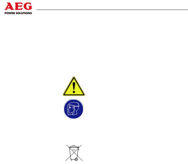
This section describes the symbols used in these instructions.
Symbol |
Meaning |
|
Hazard symbols are triangular and feature a |
|
yellow background, black border and corre- |
|
sponding symbol. |
|
|
|
Signs containing orders are round and have a |
|
blue background with a white symbol. |
|
|
i |
Information is indicated by the letter i. These |
sections contain important information about the |
|
phases of the equipment's service life. |
|
|
|
|
Instructions relating to the environment are |
|
identified by a wheelie bin. Instructions relating |
|
to the environment make reference to mandato- |
|
ry requirements set out by regional or national |
|
authorities which are of particular relevance |
|
when disposing of materials used during opera- |
|
tion, for example. |
|
|
Table 1 |
Instruction and warning symbols in these operating |
instructions |
|
Other symbols and their meanings
Typograph- |
|
|
ical element |
Meaning |
|
|
This symbol is used for action instructions. |
|
|
|
|
1. |
Numbers are used for action instructions that |
|
2. |
||
need to be followed in a specific order. |
||
3. |
||
|
||
|
|
|
|
This symbol is used for bulleted lists. |
|
|
|
|
|
References to figures, chapters or tables are |
|
shown using the symbol on the left. |
||
|
||
|
|
|
Table 2 – Other symbols |
||
10 of 72 |
8000047961 BAL |
Protect PV.630 Operating Instructions
2.2 |
Safety Instructions |
|
|
|
|
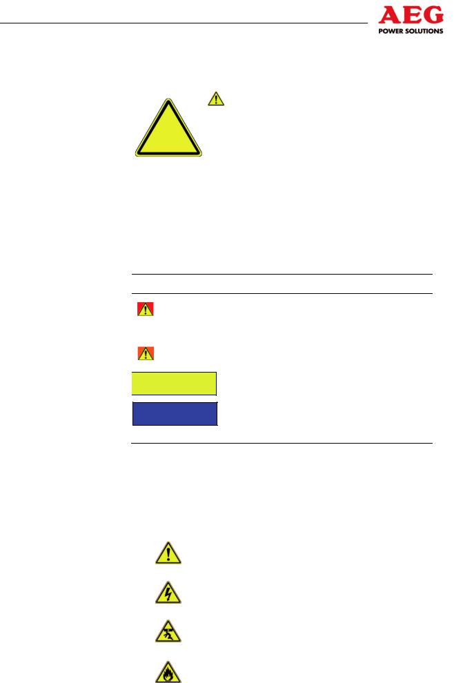
All safety instructions have the following structure: |
|
|
|
|
|
|
|
|
SIGNAL WORD |
|
|
|
Type and source of hazard |
|
|
Symbol |
Consequence(s) of noncompliance |
|
|
|
Measure(s) to avoid hazard. |
|
|
|
|
Figure 1 Warning associated with operator action
2.2.1Signal Words Used
Signal words at the start of safety instructions indicate the type and severity of the consequences if the measures for avoiding the hazard are not taken.
Warning colour Consequences
|
|
Warns of a situation posing an immediate |
|
DANGER |
|||
|
hazard which will lead to death or serious |
||
|
|
||
|
|
injury. |
|
|
|||
|
|
Warns of a situation posing a possible haz- |
|
WARNING |
|
||
|
ard which may lead to death or serious injury. |
||
|
|
|

 CAUTION
ATTENTION
Warns of a situation posing a possible hazard which may lead to minor injury.
Warns of possible damage to property and the environment which could interrupt operation.
2.2.2Hazard Symbols Used
The following hazard symbols are used to illustrate hazards in the safety instructions.
Symbol |
Meaning for skilled personnel |
|
General hazard source |
|
|
|
Electrical hazard |
|
|
|
Risk of falling loads |
|
|
|
Risk posed by flammable material |
|
|
8000047961 BAL |
11 of 72 |
Protect PV.630 Operating Instructions
Risk posed by corrosive vapours and liquids
Risk posed by explosive material
Table 3 – Hazard symbols
2.2.3Signs Containing Orders for Personal Protective Equipment
The following signs relate to the use of personal protective equipment. You are required to comply with them.
Symbol |
Meaning for skilled personnel |
|
Wear a face shield. |
|
|
|
Wear an electrician's safety helmet. |
|
|
|
Wear insulating safety boots. |
|
|
|
Wear insulating overalls. |
|
|
|
Wear insulating gloves with long sleeves. |
Wear hearing protection when operating the equipment.
Table 4 Signs containing orders for PPE
Check that personal protective equipment is in perfect working order and report any defects you notice to the equipment operator.
12 of 72 |
8000047961 BAL |

Protect PV.630 Operating Instructions
2.2.4Abbreviations
The following abbreviations are used in these operating instructions:
DOU |
Display and operation unit |
AC |
Alternating current |
BGV |
Regulation set out by Employer's Liability Insurance |
|
Association (Germany) |
CAN |
Controller Area Network |
CNF |
Manufacturing order number |
DC |
Direct current |
DCD/ACD |
DC/AC control cabinet |
DCS |
Distributed control system |
DIN |
German Standards Institute |
EPO |
Emergency power off (system off) |
GCB |
Generator connection box |
Grid |
Power utility mains (power utility company's mains) |
IEC |
International Electrotechnical Commission |
IGBT |
Insulated gate bipolar transistor |
INV |
Inverter cabinet |
PE conductor Protective earth conductor, earthing |
|
PV |
Photovoltaics |
VDE |
Verband der Elektrotechnik Elektronik Informations- |
|
technik e. V. (German Association for Electrical, |
|
Electronic & Information Technologies) |
INV |
Inverter |
2.3Emergency Procedure (e.g. in the Event of a Fire)
Never put your own life at risk. Your own safety is paramount.
Call the fire brigade.
Call the emergency doctor, if necessary.
Shut down the equipment using the system stop switch (ensuring your own safety).
2.4Safety Awareness
The qualified skilled personnel defined in Chapter 1.3.2 are responsible for safety. The member of personnel who is responsible for the equipment must ensure that only suitably qualified persons are allowed access to the equipment or permitted within its vicinity.
The following points must be observed:
All such working procedures which are detrimental to the safety of persons and the operation of the equipment in any way are prohibited.
The equipment may only be operated when in perfect working order.
Never remove or render inoperable any safety devices.
8000047961 BAL |
13 of 72 |
Protect PV.630 Operating Instructions
All necessary operational measures must be initiated prior to deactivating any safety device in order to perform maintenance, repair or any other work on the unit.
Safety awareness also entails informing colleagues of any unsuitable behaviour and reporting any faults detected to the appropriate authority or person.
The member of personnel responsible for the equipment must ensure that:
The safety instructions and operating instructions are readily available and are complied with
The operating conditions and technical data are observed
Safety devices are used
The prescribed maintenance work is performed
Maintenance personnel are informed without delay or the equipment is shut down immediately in the event of abnormal voltages or noise, high temperatures, vibrations or any similar phenomena, so that the cause of this can be determined
2.5Particular Dangers associated with Photovoltaic Systems
Here you will find information about the additional dangers associated with photovoltaic systems.
An active power source is connected. Depending on the operating status, the PV cells and the equipment may be live.
 DANGER
Contact with voltage! Extremely high DC voltages of up to 1000 VDC are present.
Risk to life due to electric shock.
Do not touch live parts.
Wear personal protective equipment ( Chapter 2.2.3).
Crystalline silicon cells
Crystalline PV cells (silicon cells) usually have an IT system configuration, i.e. a non-earthed system that will be inadvertently earthed in the event of an earth fault.
A generator with a complex branched structure can only be shut down with a great deal of difficulty (in the event of a short circuit, for example).
Thin-film cells
To prevent corrosion, thin-film cells must be earthed.
Lightning protection
The desired level of protection can only be achieved if a lightning protection zone concept has been implemented for the building where the unit is to be installed, in accordance with DIN VDE 0185-4.
14 of 72 |
8000047961 BAL |

Protect PV.630 Operating Instructions
System stop switch
The system stop switch is on the door of the equipment's DC/AC control cabinet.
The system stop switch is not intended for switching off the equipment. It may only be used in an emergency.
The DOU is used, amongst other things, to switch the equipment on and off.
The system stop switch causes the
-PV inputs
-mains input and
-mains 2 input
to be separated. This interrupts the energy supply.
It does not mean that the unit has been de-energised!
2.6Safety Signs and Warning Notices on the Equipment
Safety signs and warning notices are located in the vicinity of danger spots. They provide information about electrical hazards and residual hazards associated with working on and with the equipment.
Safety signs and warning notices must always be in perfect condition and clearly legible. You must comply with safety signs and warning notices whenever you are working on or with the equipment.
2.7Safety and Protection Devices for the Equipment
This section describes all safety and protection devices. Safety and protection devices protect personnel against hazards which cannot be countered by safe design.
Safety and protection devices must always be in perfect working order.
2.7.1Protective Covers
The equipment is designed so that the live components in the operating area are secured with protective covers wherever possible. The protective covers provide protection against accidental contact with live parts.
Such protection may only be removed for start-up and for maintenance or repair work.
The covers must be replaced immediately on completion of such work and checked to ensure that they are in perfect working order.
8000047961 BAL |
15 of 72 |

Protect PV.630 Operating Instructions
2.7.2Lockable Equipment Doors
The equipment doors are fitted with a control cabinet lock. This prevents unauthorised personnel from accessing the equipment. The equipment door must be kept closed at all times.
It may be opened for maintenance and repair work.
i |
The space requirement for the opened equipment doors |
|
|
|
must be taken into account |
|
|
The equipment door must be closed again once maintenance and repair work is complete.
2.7.3Guard
The guard forms the equipment's housing. It protects against unintended contact with live parts and electromagnetic rays.
It may be removed for maintenance and repair work.
i |
The area around the equipment must be made secure |
|
when the guard is removed. |
|
|
The guard must be put back in place once maintenance and repair work is complete.
2.8Residual Hazards
This section describes residual hazards. Despite the measures taken to ensure safety and protection, the equipment poses residual hazards which cannot be countered by design.
Observe warnings at all times while you are working.
16 of 72 |
8000047961 BAL |
Protect PV.630 Operating Instructions
2.8.1Electrical Hazards
 DANGER
Contact with voltage!
Risk to life due to electric shock.
Use dry insulating material to remove the victim from the live parts.
Seek medical assistance and inform the control room.
Disconnect the equipment safely.
 DANGER
Electric shock after activating “System stop”!
Parts of the equipment remain live after “System stop” has been activated (e.g. external voltage present at remote signal terminals).
Risk to life due to electric shock.
Disconnect the equipment safely.
 DANGER
Electric shock caused by inverter.
Parts of the equipment remain live after the inverter has been shut down.
Risk to life due to electric shock.
Disconnect the equipment safely.
 DANGER
Electric shock caused by back feeding.
The input terminals of the equipment may remain live after the incoming power supply has been interrupted.
Risk to life due to electric shock.
Disconnect the equipment safely.
Install back feeding protection (a disconnector) in the load circuit.
 DANGER
Electric shock caused by leakage currents.
The capacitors generate high leakage currents in the equipment. Conductive parts may be live in the event of connection errors.
Risk to life due to electric shock.
Establish a PE conductor connection prior to start-up.
8000047961 BAL |
17 of 72 |
Protect PV.630 Operating Instructions
i |
Using residual-current-operated safety devices (FI) alone |
|
is not permitted. |
WARNING
Water in electrical equipment!
Risk to life due to electric shock.
Do not use water to clean the cabinets.
Do not place any vessels containing fluids on electrical equipment.
2.8.2Risks Due to Moving Parts
 CAUTION
Risk of injury due to rotating fans!
The fans of the INV control cabinet are freely accessible.
Never reach into rotating fans.
When setting up any system, ensure that the fans cannot be touched.
2.8.3Fire-Related Risks
Installation of fireproof enclosures (EN 60950-1)
A built-in floor plate ensures that, in the event of a fire, no molten or burning material can fall out of the equipment.
We recommend having a separate supply/exhaust air connection for the PV.630 in order to prevent smoke spreading in the event of a fire.
 WARNING
Spread of smoke in electrical operating areas.
If smoke is detected or a fire breaks out, immediately disconnect the equipment from the power supply and inform the maintenance personnel.
18 of 72 |
8000047961 BAL |
Protect PV.630 Operating Instructions
2.8.4Risks due to Loss of Control
ATTENTION
Failure of remote signalling.
If remote signalling fails or the signal lines are interrupted, the control room can no longer control the equipment.
In such an event, faults can only be identified locally at the unit itself.
Failure of external emergency switching device Disconnect the equipment safely.
 ATTENTION
Failure of the display and operation unit.
If the display and operation unit fails, the skilled personnel will no longer be able to control the equipment.
In such an event, faults will no longer be displayed.
Inform the control room.
2.8.5Risks from Maintenance and Repair Work
iOnly trained and qualified skilled personnel (as described above) may work on or around the equipment while strictly observing the safety regulations.
 DANGER
Risk to life due to electric shock.
Potentially fatal voltages are present in the equipment.
Disconnect safely.
Secure the unit against being switched back on.
Verify that all poles are de-energised.
Earth and short-circuit the equipment.
Provide protection in the form of covers or barriers for any neighbouring live parts.
 ATTENTION
Damage to property.
Only use original spare parts.
Do not intervene in the equipment without authorisation to do so.
Observe the safety regulations.
8000047961 BAL |
19 of 72 |
Protect PV.630 Operating Instructions
3 Product Details
The equipment has been designed for solar power plants and provides professional solutions for the use of installations covering large roofs or in open spaces.
3.1Product Description
The equipment is a solar inverter (INV) that feeds the electrical energy produced by the PV cells into a medium-voltage mains (e.g. 10 kV; 20 kV; 33 kV).
The required mains transformer is not supplied with the unit and can be ordered as an extra if necessary. It is possible to combine two Protect PV.630 units to create a 1.26 kW system. A joint isolating transformer can be used, with an electrically isolated lowvoltage connection for each Protect PV.630. 1.26 MW systems can be made to support “partner operation” to increase their efficiency.
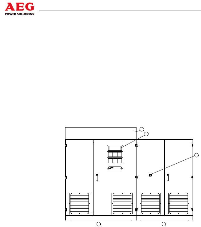
The rating plate, featuring all the relevant data, is located on the inside of the door.
|
3 |
|
1 |
|
2 |
A |
B |
Figure 2 PV.630 equipment
|
Item |
|
Designation |
|
|
|
|
|
|
|
|
|
1 |
|
Display and operation unit (DOU) |
||
|
|
|
|
|
|
|
2 |
|
System stop |
|
|
|
|
|
|
|
|
|
3 |
|
Fan assembly (fan cover optional) |
||
|
|
|
|
|
|
|
A |
|
INV control cabinet |
+INV |
|
|
|
|
|
|
|
|
B |
|
DC/AC control cabinet |
+DCD/ACD |
|
|
|
|
|
|
|
|
|
|
|
|
|
|
i |
|
Important information about equipment documenta- |
|
|
|
|
tion |
|
|
|
|
|
Further descriptions and unit diagrams are included in the |
|
||
|
|
|
document folder. |
|
|
|
|
|
|
|
|
20 of 72 |
8000047961 BAL |

Protect PV.630 Operating Instructions
3.2Dimensions and Views
|
2700 |
|
|
07 |
|
|
|
02 |
|
|
|
|
11,5 |
600 |
75 |
1500 |
1200 |
|
|
|
|
600 |
|
660 |
|
625 |
|
925 |
|
|
|
Figure 3 Dimensions and views
3.3Appropriate Use
Only operate the equipment with the maximum permissible connection values stated in the technical data sheet. Any other use or modification constitutes inappropriate use.
Unauthorised repairs, manipulations or changes made to the equipment and its safety devices without the manufacturer's approval are not permitted. The manufacturer cannot be held liable for damage resulting from such repairs, manipulations or changes.
Safety
The equipment will operate reliably and safely subject to compliance with the instructions, the operating and equipment specifications and regulations set out by the Employer's Liability Insurance Association.
8000047961 BAL |
21 of 72 |
Protect PV.630 Operating Instructions
3.4Inappropriate Use
No liability is accepted if the equipment is used for applications not intended by the manufacturer (= inappropriate use). Inappropriate use can cause serious or fatal personal injury. The responsibility for any measures necessary for the prevention of personal injury or damage to property is borne by the equipment operator or user.
3.5Standards, Directives and CE Mark
The equipment complies with currently applicable DIN and VDE regulations. The requirements of BGVA3 are met on the basis of compliance with EN 50274/VDE 0660-51.
The requirements of VDE 0100, Part 410, IEC 60364-4-41, “Functional extra-low voltage with safe isolation” and IEC 62109, “Safety of power converters for use in photovoltaic power systems” have been complied with where applicable.
The CE mark on the unit confirms compliance with the EC framework directives for 2006/95/EC (Low Voltage) and for 2004/108/EC (Electromagnetic Compatibility), provided that the actions outlined in the instructions are observed.
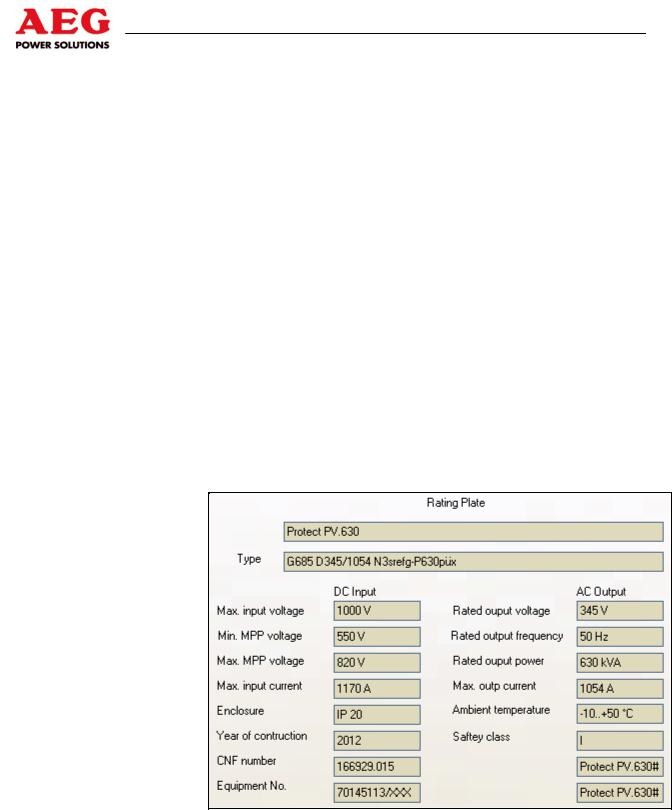
3.6Nameplate
The following information appears on the nameplate:
Figure 4 Rating plate (example)
22 of 72 |
8000047961 BAL |
Protect PV.630 Operating Instructions
3.7Technology
Due to the utilisation of high-performance electronic components, the equipment boasts a very high degree of operational reliability, is extremely efficient and is characterised by its versatility in communicating with other systems by means of interfaces.
The entire control electronics system for the equipment is based on the use of microcomputer assemblies. The fact that the various assemblies are logically integrated and linked into the overall system means that unit properties can be defined by making unitspecific parameter settings in the software.
Information is exchanged between the individual modules using the CAN bus (Controller Area Network). This CAN bus features high interference immunity and is used in a wide variety of industrial applications.
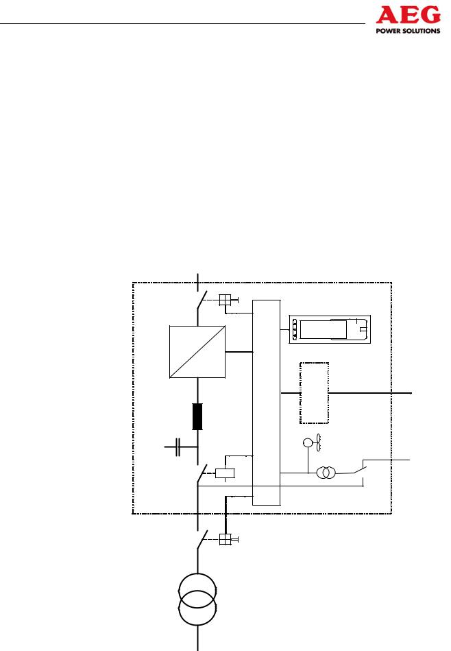
The figure below illustrates the principle of the equipment.
DC |
|
|
(PV-modules) |
Protect PV.500 |
|
|
|
|
Q4 |
|
|
|
Display |
|
= |
|
|
~ |
|
|
~ |
Communication |
|
|
|
|
unit |
M |
|
Control |
supply |
|
|
Control unit |
|
K7 |
|
AC mains 2 |
|
|
|
Q26 |
|
|
Medium-voltage mains
Figure 5 Functional principle of the equipment for connection to a lowvoltage mains
8000047961 BAL |
23 of 72 |
Protect PV.630 Operating Instructions
The main assemblies of the inverter are:
DC load interrupter switch Q4
Inverter stack, display and control unit with communication components
AC filter
Inverter output contactor K7
Mains transformer (external)
Mains disconnector Q26 (external)
The PV cells supply the inverter stack with DC voltage via DC load interrupter switch Q4. The inverter stack converts this DC voltage into a 3-phase AC voltage. A sinusoidal current is fed into the mains via the AC filter, inverter output contactor K7 and the mains transformer.
 DANGER
Risk to life due to electric shock.
Potentially fatal voltages are present at the terminals on the equipment.
Do not touch live parts.
Mains disconnector Q26 (external) and the isolator in the generator connection box (GCB) are there to isolate the inverter in the event of unit faults or when maintenance needs to be performed on the unit.
The control unit is supplied with power from the AC mains or, optionally, from a second AC mains.
3.8Operating Elements
For details of how the internal operating elements are arranged, please refer to the documents included in the unit.
24 of 72 |
8000047961 BAL |

Protect PV.630 Operating Instructions
4 System Description
This chapter describes the operating modes and functions of the equipment.
4.1Operating Modes
Two different operating modes may be used:
Individual operation
Partner operation
4.1.1Individual Operation
In individual operation, the inverter works independently and is not connected to any other inverters. The DC infeed from the PV cells and the link to the AC mains are only connected to this inverter.
Switching operations, control commands and modifications to setting parameters are only performed by the unit concerned.
4.1.2Partner Operation
In partner operation, two inverters are connected via a CAN bus. The DC voltage infeeds of both units can be linked using a coupling breaker. Levels of efficiency can be increased in this operating mode by running one inverter on two connected PV cells at less than full power. It is the inverter itself that connects and disconnects the DC voltage; it is also responsible for switching the units on and off.
This operating mode is described in detail in Chapter 5.5.
8000047961 BAL |
25 of 72 |
Protect PV.630 Operating Instructions
5 System Function
5.1Description of Sequence Control
As soon as the equipment's control module is supplied with voltage, sequence control starts.
Initially, load interrupter switch Q4 remains open. Once the initialisation phase is complete and if no deactivating faults are pending, load interrupter switch Q4 is closed. During subsequent operation, the switch is only opened by deactivating faults ( Chapter 6).
Inverter output contactor K7 remains open initially. The contactor is switched by the sequence control.
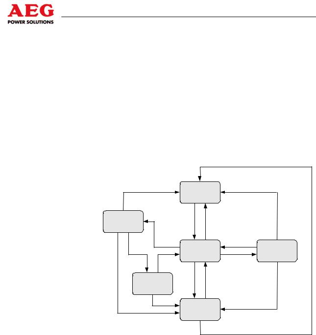
The figure below provides a graphical illustration of the sequence control statuses.
|
OFF command |
OFF command |
|
|
|
OFF |
|
Operation |
ON command |
OFF command |
|
|
Feed-in |
|
|
|
conditions met |
Daytime detection |
|
|
|
|
|
|
Waiting for feed |
Night |
|
|
conditions |
||
|
|
||
Operating |
Delay |
Night-time detection |
|
conditions |
|
|
|
no longer |
complete |
|
|
met |
|
|
|
Fault |
|
|
|
|
Fault |
Fault |
|
|
acknowledgement |
|
|
|
Waiting |
|
|
|
|
|
|
|
Fault |
|
|
|
|
Fault |
|
|
|
Fault |
|
|
|
OFF command |
|
Figure 6 Sequence control
5.1.1The “OFF” Status
The equipment has been switched off logically via the DOU or the master control unit.
The equipment is running without faults, the monitoring systems are not activated.
In this status, no power is fed into the mains.
Possible change of status:
The status can be switched from “OFF” to “Waiting for feed conditions” by switching the equipment on via the DOU and the master control unit.
5.1.2The “Waiting for Feed Conditions” Status
The values of the DC voltage on the PV cells, the mains voltage and the mains frequency are monitored by the equipment.
26 of 72 |
8000047961 BAL |
 Loading...