


3C16470
SuperStack® 3 Baseline 10/100 Switch 16-Port (3C16470) and 24-Port
(3C16471) User Guide
DUA1647-0AAA01
1
4
13
5
8
16
17
9
20
21
12
24
INTRODUCTION
The SuperStack® 3 Baseline 10/100 Switch is a versatile,
easy-to-use unmanaged switch. It is ideal for users who want the
high-speed performance of 10/100 switching but do not need
sophisticated management capabilities. The Baseline 10/100
Switch is shipped ready for use. No configuration is necessary.
The Baseline 10/100 Switch has 16 or 24 shielded RJ-45,
10/100 Mbps auto-negotiating ports on the front panel. Each port
automatically determines the speed and duplex mode of the
connected equipment and provides a suitable switched
connection. Each port also supports automatic MDI/MDI-X
detection.
The Baseline 10/100 Switch is suited for office use where it can
be free standing, or rack mounted (in a wiring closet or
equipment room).
The Baseline 10/100 Switch comes with:
One power cord for use with the Baseline 10/100 Switch
Four self-adhesive rubber pads
One mounting kit
The Switch is powered from the AC mains supply.
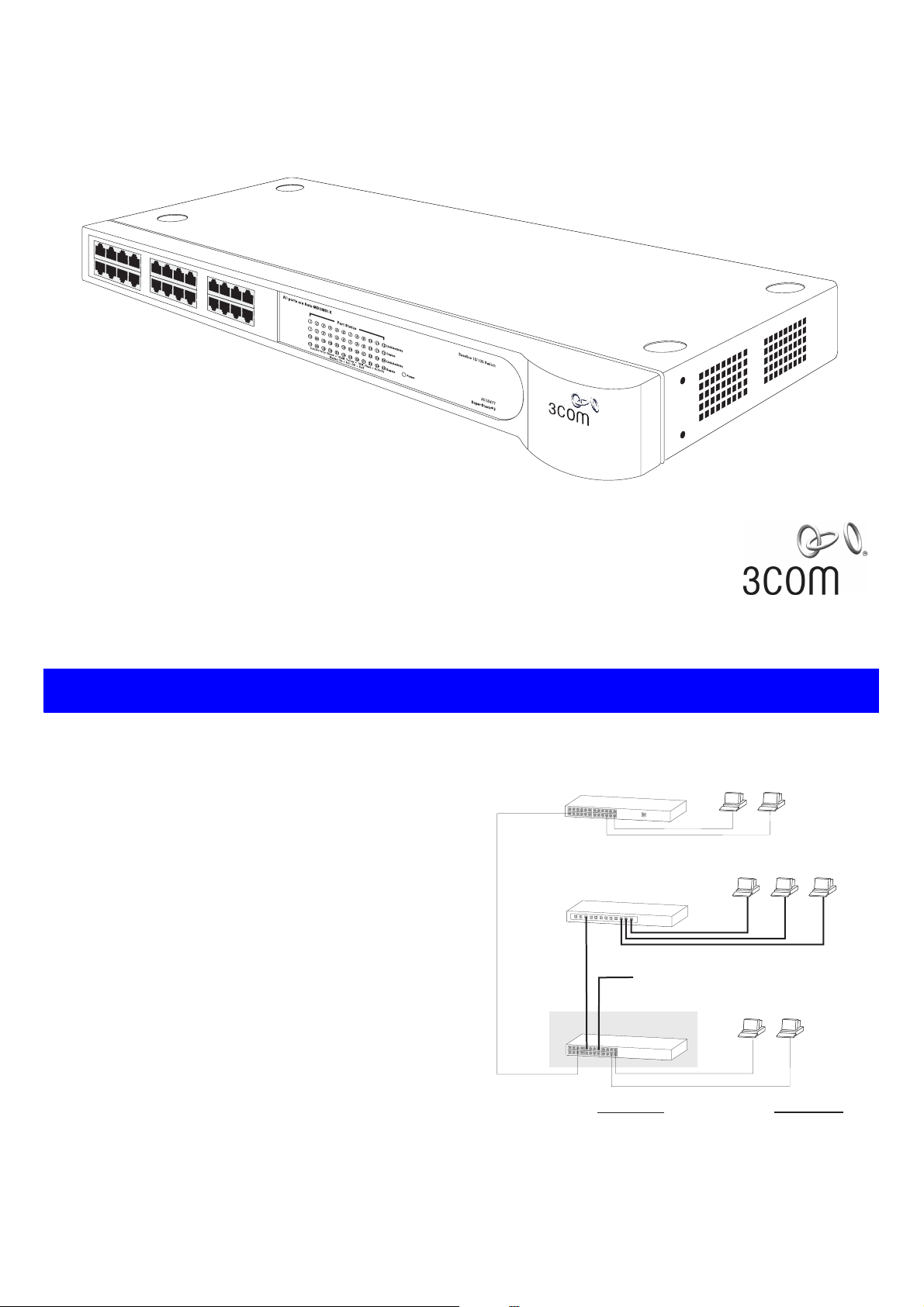
The diagram below shows an sample configuration:
Endstations on shared
Baseline Hub
Baseline Dual Speed Hub
100Mbps connection
to backbone
Baseline 10/100 Switch
10Mbps connections
Endstations on shared
100Mbps connections
Endstations on switched
10Mbps connections
100Mbps link10Mbps link
The Baseline 10/100 Switch provides high performance switched
connections to 10 Mbps and 100 Mbps hubs, servers and
workstations that require a dedicated switched link.
1
HOW TO USE THE BASELINE 10/100 SWITCH
1
1
13
5
4
16
17
9
8
20
21 24
6
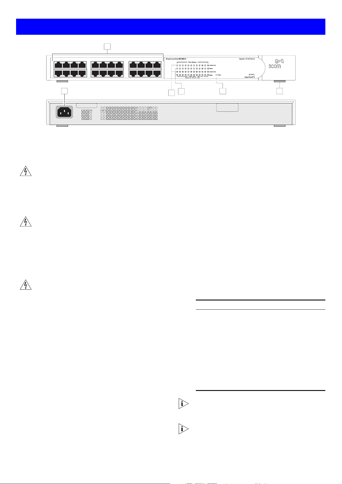
Numbered elements in this diagram refer to numbered sections in
the text. A 24-port unit is shown.
Front Panel
1 24 RJ-45 10/100 Ports
WARNING
sockets. They cannot be used as standard traditional
telephone sockets, or to connect the unit to a traditional
PBX or public telephone network. Only connect RJ-45
data connectors, network telephony systems, or network
telephones to these sockets. Either shielded or unshielded
data cables with shielded or unshielded jacks can be
connected to these data sockets.
AVERTISSEMENT: Les ports RJ-45. Ceux-ci sont
protégés par des prises de données. Ils ne peuvent pas
être utilisés comme prises de téléphone conventionnelles
standard, ni pour la connection de l’unité à un réseau
téléphonique central privé ou public. Raccorder seulement
connecteurs de données RJ-45, systèmes de réseaux de
téléphonie ou téléphones de réseaux à ces prises. Il est
possible de raccorder des câbles protégés ou non
protégés avec des jacks protégés ou non protégés à ces
prises de don.
WARNUNG: RJ-45-Porte. Diese Porte sind geschützte
Datensteckdosen. Sie dürfen weder wie normale
traditionelle Telefonsteckdosen noch für die Verbindung
der Einheit mit einem traditionellem privatem oder
öffentlichem Telefonnetzwerk gebraucht werden. Nur
RJ-45-Datenanscluße, Telefonnetzsysteme or Netztelefone
an diese Steckdosen anschließen. Entweder geschützte
oder ungeschützte Buchsen dürfen an diese
Datensteckdosen angeschlossen werden.
10BASE-T/100BASE-TX Ports
The Baseline 10/100 Switch has 16 (3C16470) or 24
(3C16471) 10/100 Mbps auto-negotiating ports.
To connect a device to the Baseline 10/100 Switch, use
Category 5 unshielded or shielded (screened) 100 Ohm
TP cable (or Category 3 cable for a 10 Mbps connection).
The maximum length of cable for each connection is
100m (328ft). Connect one end of the cable to an RJ-45
port on the Baseline 10/100 Switch, and the other end to
the appropriate RJ-45 port on the connecting device.
Each port on the Baseline 10/100 Switch is
auto-negotiating: its speed and duplex mode (half duplex
or full duplex) are automatically determined by the
capabilities of the connected device.
: RJ-45 ports. These are shielded RJ-45 data
12
3
2
4
5
Each port supports automatic MDI/MDI-X detection and
can be connected to either a 10BASE-T or a 100BASE-TX
device.
The Switch offers priority queuing, which means all
packets that are received are examined to see if they have
been priority encoded. If a packet has been then the
Switch will read the priority level and determine whether
the packet should be directed through the normal or high
priority channel. This feature can be useful for example
during excessive loads when one type of traffic may
require priority over another. The Switch is configured to
comply with 802.1p, VLAN tagged frames.
Traffic prioritization ensures that high priority data is
forwarded through the Switch without being delayed by
lower priority data. It differentiates traffic into classes and
prioritizes those classes automatically. Traffic prioritization
uses the multiple traffic queues that are present in the
hardware of the Switch to ensure that high priority traffic
is forwarded on a different queue from lower priority
traffic, and is given preference over that traffic. This
ensures that time-sensitive traffic gets the highest level of
service. The 802.1D standard specifies eight distinct levels
of priority (0 to 7), each of which relates to a particular
type of traffic. The priority levels and their traffic types
are shown in the following table.
Priority Level Traffic Type
0 Best Effort
1 Background
2 Standard (spare)
3 Excellent Effort (business critical)
4 Controlled Load (streaming multimedia)
5 Video (Interactive media), less than 100
6 Voice (Interactive voice), less than 10
7 Network Control Reserved traffic
millisecondsn latency and jitter.
milliseconds latency and jitter.
The traffic prioritization feature supported by the Switch
is compatible with the relevant sections of the IEEE
802.1D standard (incorporating IEEE 802.1p).
If you connect two Baseline 10/100 Switch units together,
the link between them operates at 100 Mbps full duplex.
You must use Category 5 cable when connecting the
units.
2

CAUTION: The Baseline 10/100 Switch supports full
duplex auto-negotiation. If the connected device does not
!
support auto-negotiation, the Switch will operate in half
duplex mode (even if the device is operating in full duplex
mode). In such a configuration, you may notice some
degradation of network performance. 3Com recommends
that you use devices that are capable of auto-negotiation
(and that you ensure that auto-negotiation is enabled, if
it is a configurable option).
Activity/Link/Speed Status LEDs
2
The first (top) and third row of LEDs, which are colored yellow or
green, show the activity and speed status of the related ports:
Status Meaning
On The link has been established.
Flashing Packets are being received or transmitted on the port.
Off If the link has not been established, either nothing is
Green The link is operating at 100 Mbps.
Yellow The link is operating at 10 Mbps.
connected to the port, or there is a problem:
■ Check that the attached device is powered on.
■ Check that the cable is the correct type and is not faulty.
If these checks do not identify the cause of the problem, it
may be that the unit or the device connected to the port is
faulty. Contact your supplier for further advice.
Status Meaning
On Yellow The port is operating in full-duplex mode.
Off The port is operating in half-duplex mode.
4
Power LED
The Power LED shows the power status of the Switch:
Status Meaning
On Green The unit is powered on and ready for use.
Off The unit is not receiving power:
■ Check the power cord is connected correctly.
■ If the unit still does not operate, contact your supplier.
5
Self-adhesive Pads
The unit is supplied with four self-adhesive rubber pads.
You do not need to apply the pads if you intend to rack
mount the unit.
If the unit is to be part of a free standing stack, apply the pads to
each marked corner area on the underside of the unit. Place the
unit on top of the lower unit, ensuring that the pads locate with
the recesses of the lower unit.
3
Duplex Status LEDs
The second and fourth (bottom) row of Status LEDs, which are
colored yellow, show the duplex status of the related ports:
INSTALLING THE SWITCH
Positioning the Baseline 10/100 Switch
CAUTION: If installing the Baseline 10/100 Switch in a
stack of different size SuperStack 3 units, the smaller
!
units must be installed above the larger ones. Do not
have a free-standing stack of more than six units.
When deciding where to position the Baseline 10/100 Switch
ensure that:
It is accessible and cables can be connected easily.
Cabling is away from sources of electrical noise such as
radios, transmitters and broadband amplifiers, and away from
power lines and fluorescent lighting fixtures.
The Switch is situated away from sources of electrically
conductive dust, for example laser printers.
The AC supply used by the Switch is separate to those used
by units that generate high levels of AC noise, for example air
conditioning units and laser printers.
Water or moisture cannot enter the case of the unit.
Air flow around the unit and through the vents in the side of
the case is not restricted (3Com recommends that you
provide a minimum of 25 mm (1 in.) clearance).
To prolong the operational life of your units:
Never stack units more than six high if free-standing, and
ensure that cables are supported so that they do not cause
the stack to fall over.
Do not place objects on top of any unit or stack.
Do not obstruct any vents at the sides of the case.
Rear Panel Connections
6 Power Supply
The Baseline 10/100 Switch automatically adjusts to the supply
voltage. Only use the power cord that is supplied with the
Baseline 10/100 Switch.
Rack Mounting
The Baseline 10/100 Switch can be mounted in a 19-inch
equipment rack using the Mounting Kit. Refer to “Mounting Kit
Instructions” on page 5.
Power Up
Use the following sequence to power up the Baseline 10/100
Switch:
1 Check the network connections and cables.
2 Connect the power supply cable to the appropriate power
socket on the rear panel of the unit; refer to 6 Power
Supply
.
3 Connect the plug to the power supply outlet socket and
switch on the power supply at the socket.
When the switch is powered on, the Power LED should be lit on
green. If it is not, refer to 4 Power LED.
Spot Checks
At frequent intervals you should visually check the Baseline
10/100 Switch. Regular checks can give you an early warning of a
possible failure; any problems can then be attended to when
there will be least effect on users. Check that all external cabling
connections are secure and that no cables are pulled taut.
If you experience any problems operating the Baseline 10/100
Switch, refer to “Problem Solving” on page 5.
3
 Loading...