


5 ELECTROMAGNETIC LAMP
|
|
CONTROL GEAR |
BALLASTS |
1 |
|
5 |
|
|
1 |
1 |
Main ballast functions |
In chapter 2.1 of this Guide: General aspects, section 2.1: Main ballast functions, the main functions of ballasts have been described.The term ‘ballasts’ is generally reserved for current limiting devices, including resistors, choke coils and (autoleak) transformers. Other pieces of auxiliary equipment are compensating capacitors, filter coils and starters or ignitors. Some systems use an additional series capacitor for stabilisation.
With the components summed up, all control functions which are necessary to operate standard fluorescent lamps can be carried out. Special arrangements, including sequence start, constant wattage or dimming circuits will not be described in this Guide, as such circuits are more and more being replaced by the modern high-frequency (HF)systems.


 1
1 
 2
2 
 Stabilisation
In section 3.2: Stabilisation, the need for current stabilisation in fluorescent lamps has been described, resulting in the following two formulae:
|
Ilamp = (Vmains - Vlamp) / Zballast |
|
and: |
Plamp = Vlamp . Ilamp . αlamp |
|
where |
Ilamp |
= the current through the lamp |
|
Vmains |
= the mains voltage |
|
Vlamp |
= the voltage across the lamp |
|
Zballast |
= the impedance of the ballast |
|
Plamp |
= the power of the lamp |
|
αlamp |
= a constant called lamp factor |
From these formulae it can be concluded that the power of the lamp (and therefore the light output) is influenced by:
-the lamp voltage Vlamp, which in turn is highly dependent on
the operating temperature (see section 5.3.12:Ambient and operating temperatures) and on the lamp current, according to the negative lamp characteristic (see section 3.2: Stabilisation).
-the lamp current Ilamp, which is dependent on the mains voltage (see section 5.3.13: Effects of mains voltage fluctuations), the lamp voltage
and the linearity of the ballast impedance.
In order to avoid undesirable variations in light output as a consequence of mains voltage fluctuations, the lamp voltage must be not more than approx. half the value of the mains voltage (100 to 130V) and the impedance should be as linear as possible.


 1
1 
 3
3 
 Ignition and re-ignition
In chapter 3: Lamps, section 3.3: Ignition, the need for ignition of a fluorescent lamp has been described.
107
5 |
|
1.3 |
Ignition and re-ignition |
|
|
In the case of electromagnetic control gear, a combination of preheating |
|
|
|
and a high ignition peak is obtained by using a normal choke ballast |
|
|
|
and a preheat starter or an electronic ignitor. |
|
|
|
Energy is supplied to the discharge in the form of electrons.The lamp |
|
|
|
current, just like the mains voltage, is sinusoidal, with a frequency of |
|
|
|
50 or 60 Hz. If the energy flow is zero (at lamp current reversal) the |
|
|
|
lamp stops burning and in theory would have to be re-ignited. |
|
|
|
This could be done by supplying additional energy to the electrodes |
|
|
|
via a higher lamp voltage, the way it is done when initially starting the |
|
|
|
lamp. But from the moment the lamp has reached its stationary |
|
|
|
condition, the lamp voltage is constant. |
|
|
|
And yet, in practice the lamp does not extinguish at current reversal. |
|
|
|
Why not? |
|
|
|
The phase shift introduced by the inductive element of the ballast |
|
|
|
ensures that the mains voltage is not zero at that moment. Because of |
|
|
|
the inductive properties of choke coil ballasts a phase shift ϕ occurs |
|
|
|
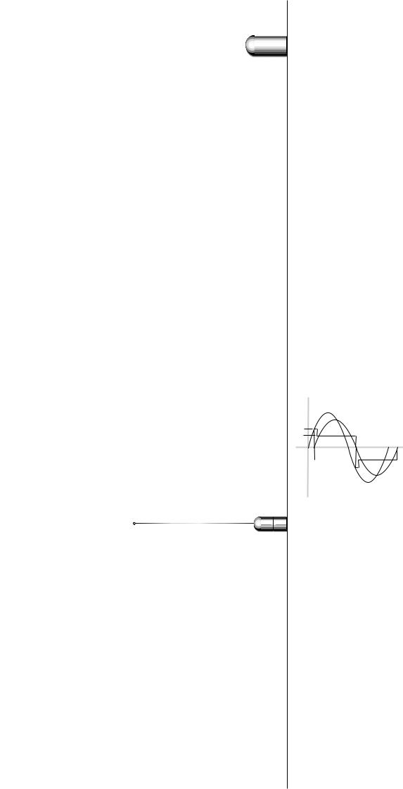
between the mains voltage and the lamp current (see Fig. 102). So, at |
|
|
|
the moment of current reversal the lamp voltage would be equal to the |
|
|
|
mains voltage, since the voltage over the ballast is nil.The difference |
|
|
|
(gap) between the mains voltage and the average lamp voltage as a |
|
|
|
consequence of the phase shift ensures proper re-ignition of the lamp |
|
|
|
at the moment the current passes the point of reversal (zero-point A |
|
|
|
in figure). |
|
|
|
V, A |
Vm |
|
|
|
|
|
|
|
Il |
Fig. 102. Phase shift between supply voltage |
gap |
Vl |
|
and lamp current (and lamp voltage) in a |
|
t |
|
|
ϕ |
||
discharge lamp with an inductive ballast. In |
|
||
|
|
||
the case shown, the supply voltage is |
|
A |
|
sufficiently high for re-igniting the lamp after |
|
|
|
ever y current reversal. |
|
|
|
1 |
4 |
Types of ballasts |
|
|
|
1 Resistor ballasts |
|
|
|
Current limitation by means of resistor ballasts is a very uneconomic |
|
|
|
form of current limitation, because in the resistor electrical energy is |
|
|
|
dissipated in the form of heat. Nevertheless, until the advent of |
|
|
|
electronic circuitry, use of a series resistor was the only way of stabilising |
|
|
|
fluorescent lamps operated on DC, for example the ‘TL’R lamp (see |
|
|
|
Fig. 103). For stable operation on a resistor ballast, it is necessary that |
|
|
|
the supply voltage be at least twice the lamp voltage under operating |
|
|
|
conditions.This means that 50 per cent of the power will be |
|
|
|
dissipated by the ballast.A considerable improvement in efficiency |
|
|
|
can, however, be achieved by using a resistor with a very pronounced |
|
|
|
positive temperature characteristic (an ordinary or specially |
|
|
|
constructed incandescent lamp serves well for this purpose). |
|
|
|
A temperature-dependent resistor compensates for variations in the |
|
|
|
lamp current resulting from variations in the mains voltage, which means |
|
|
|
108 |
|
 5
5
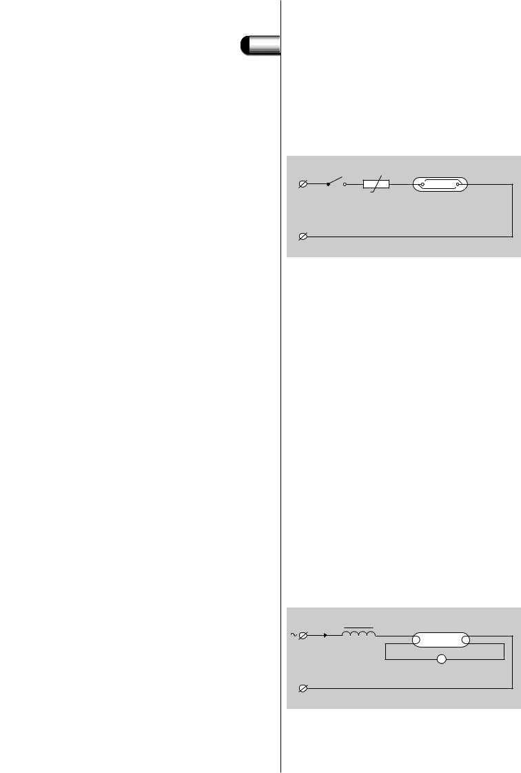
Fig. 103. Schematic diagram of a fluorescent lamp operated on a resistor ballast in a DC circuit.
Fig. 104. Schematic diagram of a fluorescent lamp operated on a choke ballast in an AC starter circuit.
1.4 Types of ballasts
that the no-load voltage need be no more than 25 to 30 per cent higher than the lamp voltage.This is also the proportion of the power dissipated by the ballast compared to the total circuit power.
‘TL’ R |
+ |
- |
2 Capacitor ballasts
A capacitor used as a ballast causes only very little losses, but cannot be used by itself, as this would give rise to very high peaks in the lamp current wave form at each half cycle. Only at very high frequencies can a capacitor serve satisfactorily as a ballast.
3 Inductive ballasts or chokes
Choke coils are frequently used as current limiting devices in gas-discharge lamp circuits (see Fig. 104).They cause somewhat higher losses than a capacitor, but produce far less distortion in the lamp current at 50 Hz. Moreover, in combination with a switch starter, they can be made to produce the high voltage pulse needed to ignite the lamp.
In practice, a choke ballast consists of a large number of windings of copper wire on a laminated iron core. It operates on the self-inductance principle.The impedance of such a ballast must be chosen in accordance with the mains supply voltage and frequency, the lamp type and the voltage of the lamp, to ensure that the lamp current is at the correct value. In other words: each type of lamp requires for each supply voltage its own choke as a ballast with a specific impedance setting. Heat losses, occurring through the ohmic resistance of the windings and hysteresis in the core, much depend upon the mechanical construction of the ballast and the diameter of the copper wire.
The right ballast for a given lamp and supply voltage should be chosen by consulting documentation and/or ballast markings.
The Philips standard range of ballasts is for supply voltages of 220/230/240 V and for frequencies of 50/60 Hz.
I b + |
B |
+ |
Vl |
- |
- |
||||
+ |
|
|
La |
|
|
|
|
|
|
Vm |
|
|
S |
|
Il 
0
-
109
5 |
1 |
5 |
1.4 Types of ballasts
The most important value for stabilisation is the ballast impedance. It is expressed as voltage/current ratio in ohm (Ω ) and defined for a certain mains voltage, mains frequency and calibration current (normally the nominal lamp current).
Chokes can be used for virtually all discharge lamps, provided that one condition is fulfilled: the mains voltage should be about twice the arc voltage of the lamp. If the mains voltage is too low, another type of circuit should be used, like the autoleak or constant-wattage circuits.
The advantages of a choke coil are:
-the wattage losses are low in comparison to those of a resistor,
-it is a simple circuit: the ballast is connected in series with the lamp.
Disadvantages of a choke coil are:
-the current in a lamp with choke circuit exhibits a phase shift with respect to the applied voltage, the current lagging behind the voltage (see also section 5.3.4: Power factor correction).
-a high starting current: in inductive circuits the starting current is about 1.5 times the rated current.
-sensitivity to mains voltage fluctuations: variations in the mains voltage cause variations in the current through the lamp.
Ballast specification and marking
There are two ways of selecting the right ballast for a certain lamp and/or to compare various ballasts:
1)the ballast marking,
2)the manufacturer’s documentation.
As all ballasts have to comply with the norm IEC 920/921 some data has to be marked on the ballast and other data can be mentioned in the documentation.
On the ballast can be found:
-marks of origin, such as the manufacturer’s name or trade mark, model or reference number, country of origin, production date code,
-rated supply voltage and frequency, nominal ballast current(s),
-type(s) of lamp with rated wattage,
-type(s) of ignitor with wiring diagram and peak voltage if this exceeds 1500 V,
- tw and t (see section 5.1.6), |
|
- max. cross-section of mains or lamp cable; e.g. 4 |
means 4 mm2, |
-symbols of the officially recognised certification institutes, such as VDE, SEMKO, SEV, KEMA, if applicable; CE marking for safety,
-in case of an independent ballast: the symbol  ; an independent ballast is a ballast which is intended to be mounted separately outside
a luminaire and without any additional enclosure,
-a symbol like  top if there are mounting restrictions,
- F-marking  if the ballast fulfils the IEC F-requirements; that means it is suitable to be mounted directly on normally flammable surfaces,
-TS, P-marking  or
or  if the ballast is thermally protected (* = thermo-switch temperature in degrees Celsius),
-indication of terminals: L for single phase, N for neutral,  for protective earth (PE),
  for functional earth,
110
 5
5


 1
1  6
6 
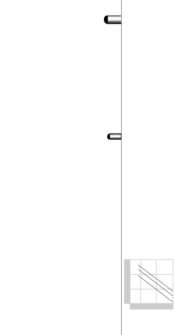
Fig. 105. The nominal life of choke coils in relation to the permitted rated maximum operating temperature of a ballast winding tw, dependent on insulation material:
a) class A: tw 105 |
ºC, |
b) class E: tw 120 |
ºC, |
c) class F or H: tw 130 |
ºC. |
1.5 Ballast specification and marking
- rated voltage, capacitance and tolerance of separate series capacitor.
In the documentation can be found:
-weight,
-overall and mounting dimensions,
-power factor (λ, P.F. or cos ϕ),
-compensating capacitor value and voltage for λ = 0.85 or 0.9,
-mains current nominal and during running-up, both with and without power factor correction,
-watt losses (normally in cold condition),
-description of version, e.g. open impregnated,‘plastic’ encapsulated, potted or compound filled.
This information suffices to find the right ballast for a certain application.Additional information can be obtained on request or can be found in special application notes. Philips ballasts are designed for use with IEC standardised fluorescent lamps.
Maximum coil temperature tw and T
A ballast, like most electrical components, generates heat due to its ohmic resistance and magnetic losses. Each component has a maximum temperature which may not be exceeded. For ballasts it is the temperature of the choke coil during operation that is important. The maximum permissible coil temperature tw is marked on the ballast. Coil insulating material, in combination with lacquer, encapsulation material etc., is so chosen that below that temperature the life specified for the ballast is achieved.A tw value of 130 ºC is usual nowadays with a coil insulating class F (150 ºC) or class H (180 ºC). Under standard conditions, an average ballast life of ten years may be expected in the case of continuous operation at a coil temperature of tw ºC.As a rule of thumb, a 10 ºC temperature rise above the tw value will halve its expected life (see Fig. 105). If, for instance, the operating temperature is 20 ºC above the tw value, one may expect a ballast life of 2.5 years of continuous operation. If no tw value is marked on the ballast, a maximum of 105 ºC is assumed for the coil temperature. As the ballast normally does not function continuously, the actual life of the ballast can be very long. It also takes some hours before the thermal equilibrium is reached in the ballast, which again increases the practical ballast lifetime.
To verify the tw marking, accelerated lifetime tests are done at ballast temperatures above 200 ºC for 30 or 60 days.
temp. (°C)
250 |
|
|
200 |
|
(c) |
|
|
|
|
|
(b) |
150 |
|
(a) |
100 |
|
|
0,1 |
1,0 |
10 |
t (years)
111
5 |
|
1 |
7 |
1.6 Maximum coil temperature tw and T
Another value marked on the ballast is the coil temperature rise t. This is the difference between the absolute coil temperature and the ambient temperature in standard conditions and is measured by a method specified in IEC Publ. 920 (EN 60920). Common values for t are from 50 to 70 degrees in steps of 5 degrees.
The coil temperature rise is measured by measuring the ohmic resistance of the cold and warm copper coil and using the formula:
|
t = {(R2 - R1)/R1} . (234.5 + t1) - (t2 - t1) |
|
or: |
tc = R2/R1 . (t1 + 234.5) - 234.5 (IEC 598-1 Appendix E) |
|
where |
R1 |
= initial cold coil resistance in ohm |
|
R2 |
= warm coil resistance in ohm |
|
t2 |
= ambient temperature at measuring R2 in Celsius |
|
t1 |
= initial ambient temperature at measuring R1 in Celsius |
|
tc |
= calculated warm coil temperature in Celsius |
|
t |
= tc - t2 in Kelvin |
|
The value 234.5 applies to copper wire; in case of aluminium |
|
|
wire, the value 229 should be used. |
|
So a ballast marked with tw 130 and t 70, will have the specified 10 years average life in continuous operation at standard conditions at an ambient temperature of 130 - 70 = 60 ºC.When the ambient temperature around the ballast is higher, a shorter ballast life has to be accepted or sufficient air circulation or cooling has to be applied. The so-called ambient temperature mentioned in this chapter is not the room or outside temperature, but the temperature of the microenvironment of the ballast. Built into a luminaire or ballast box the air temperature around the ballast is higher than the outside ambient temperature.This higher temperature has to be added to the coil temperature rise t to find the absolute coil temperature: tc = t2 + t.
Additionally, a third temperature figure can be mentioned on the ballast: the ballast temperature rise in abnormal conditions, again measured according to specifications like EN 60920. In short: it is the winding temperature rise at 110 per cent mains voltage when the glow-switch starter, belonging to the system, is short-circuited.
The marking of the three temperature markings should be :
t ** / *** / tw *** with * = figure
Example: t 70 / 140 / tw 130.
Watt losses
Ballast losses normally are published as ‘cold’ values, meaning that the ballast is not energised or only very shortly before and the ballast winding is at ambient temperature (25 ºC). In practice the ballast will reach more or less the marked t value and then the copper resistance is approx. 25 per cent higher than in the ‘cold’ situation.Therefore the ‘warm’ losses in practice will be 10 - 30 per cent higher than the published values.
112

|
1.7 Watt losses |
5 |
|
|
|
As in some applications the power consumption is of prime importance, there are low-loss ballasts for the major lamp types ‘TL’D 18, 36 and 58 W ( BTA**L31LW).The 18 and 36 W LW ballasts are bigger than the standard types, resulting in lower ballast temperatures and 25 to
30 per cent less ballast watt losses. Due to practical restrictions the BTA 58L31LW type could not be made bigger.The 15 per cent lower ballast losses are the result of a better iron lamination quality, while the ballast temperatures are only slightly lower than those of the standard types.
STARTERS


 5 2
5 2


 2
2  1
1  Main starter function
Fluorescent lamps do not ignite at mains voltage.To ignite the lamps, a starter is applied to preheat the lamp electrodes and to give a peak voltage high enough to initiate the discharge.
So in fact there is only one basic function for a starter: to deliver the ignition voltage to start the discharge in a fluorescent lamp in a proper way.After ignition the starter has to stop producing ignition peaks.This can be obtained by sensing the lamp voltage or lamp current and/or by a timer function.


 2
2  2
2  Starter types
There are two types of fluorescent lamp starters:
1 Glow-switch starters
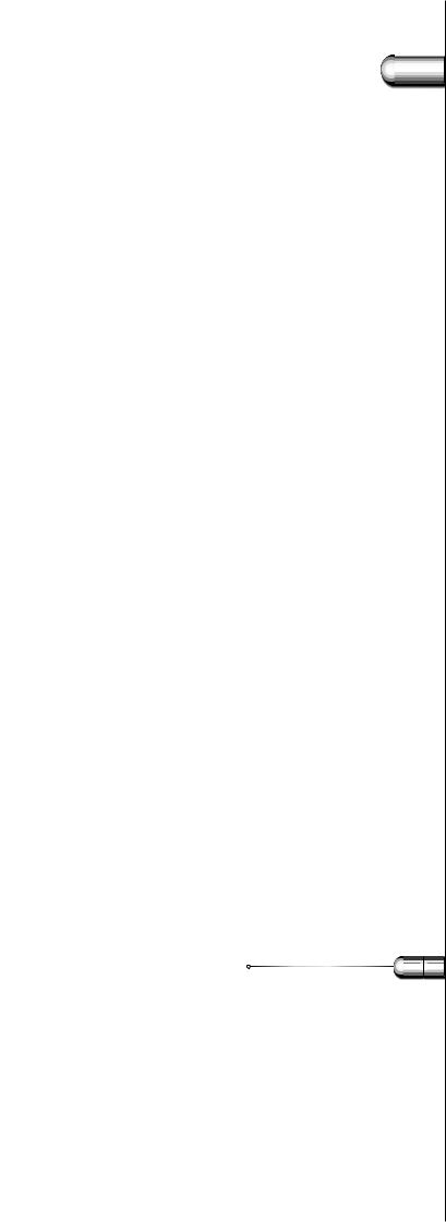
The glow-switch starter consists of one or two bimetallic electrodes enclosed in a glass container filled with noble gas.The starter is connected parallel across the lamp in such a way that the preheat current can run through the lamp electrodes when the starter is closed (Fig. 106).At the moment of switching on the mains voltage, the total mains voltage is across the open glow-switch starter.This results in a glow discharge starting between the bimetallic electrodes of the starter.The glow discharge causes a temperature increase in these bimetallic electrodes, resulting in the closure of the electrodes of the starter. During this closure the lamp electrodes are preheated by the short-circuit current of the ballast.After closure the temperature of the starter electrodes decreases and the starter re-opens.At the moment of re-opening, the current through the ballast is interrupted, causing a peak voltage over the lamp electrodes high enough for lamp ignition.This peak voltage depends on the inductance of the choke, the level of the shortcircuit current and the speed of the opening of the glow-switch electrodes. In formula:
Peak voltage:Vpeak = L dI/dt
The minimum specified peak voltage depends on the type and is between 800 and 900 V.
If the lamp electrodes are not yet hot enough or the peak voltage is not high enough, the glow-switch starter will resume the whole
113
 5
5
Fig. 106. Working principle of a glowdischarge starter circuit.
1. The heat from the discharge in the starter bulb causes the bimetallic electrodes to bend together.
2. When the bimetallic electrodes make contact, a current starts to flow through the circuit, sufficient for preheating the electrodes of the fluorescent lamp.
3. The bimetallic electrodes cool down and open again, causing a voltage peak, which ignites the fluorescent lamp.
2.2 Starter types
starting process again until the lamp ignites. If the lamp will not ignite (end of life) the starter will continue producing peaks (flickering) until the mains voltage is switched off or until the electrodes of the glowswitch starter stick together. In the latter case the short-circuit current is continuously running through the lamp electrodes, which can be seen at the glowing lamp ends.
0 |
0 |
0 |
Once the lamp is properly ignited, the lamp voltage is too low for a glow discharge between the starter electrodes. So these electrodes stay ‘cool’ and in open position.
A capacitor across the starter electrodes prevents radio-interference of the lamp.
There are five types of glow-switch starters, specified for a certain mains voltage and/or lamp wattage ( S2-10-11-12-16).There are also resettable glow-switch starters: SiS2, Si S3 and SiS10.These starters switch off after a certaintime in case the lamps do not ignite and have to be reset manually by a push button. Switching the mains supply does not reactivate a switched-off resettable starter.
114

5 |
|
2 |
3 |
SYSTEMS |
3 |
5 |
|
3 |
1 |
2.2 Starter types
2 Electronic starters
In principle the electronic starter or ignitor is working in the same manner as the glow-switch starter. But now the switching does not come from bi-metallic electrodes, but from a triac.
The electronic circuit in the starter gives a well-defined preheat time (1.7 sec) for the lamp electrodes and, after the preheat, a well-defined peak voltage, which ensures optimum lamp ignition.The heart of the electronic starter is a customized integrated circuit, containing the intelligence of the product. It makes the starter switch off after seven unsuccessful ignition attempts, so it is called ‘flicker free’.
The electronic starter also contains an over-heating detection by means of a PTC resistor, to switch off in case the starter becomes too hot (e.g. with a short-circuited ballast).This second stop function resets after approx. 4 minutes.
The electronic starter extends the lamp lifetime up to 25 per cent on account of the well-defined preheat time.The exact digital timing makes the electronic starter independent of mains voltage fluctuations.
In the Philips programme there are two types of electronic starters: one in the canister of the glow-switch starters (two-pin types S2-E and S10-E Perform version), and one in a plastic housing (four-pin type ES08).
Lifetime
The lifetime of fluorescent lamp starters is expressed in the number of switches.
At present the glow-switch starters have a lifetime of 10 000 switches or more, while the electronic starters have a lifetime of 100 000 switches or more.
Components
A customer primarily needs a solution to his lighting requirements. Basically, he needs two things to obtain an installation which completely fulfils his specifications: a design and components.To make sure that the installation works properly under all circumstances, the right components must be chosen and selected in combination with each other.
In principle the following components are required in a lighting installation:
-lamps,
-lampholders,
-luminaires,
-gear (ballasts, starters),
-compensating capacitors,
-cabling,
-fusing and switching devices,
-filter coils (if necessary),
-dimming equipment (if possible and required).
115
 5
5
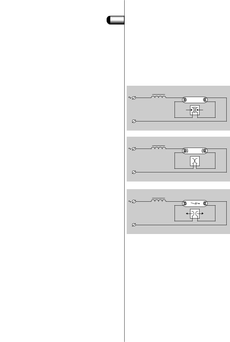
Fig. 107. The circuit of an SL lamp consists of the following components:
1. Discharge tube,
2. Starter,
3. Capacitor,
4. Ballast,
5. Thermal protector.


 3
3 

 2
2 

3.1 Components
Information about lamps can be found in the lamp documentation, where also the type of lampholder or lamp cap is mentioned. Be sure to use the appropriate lampholder, as there are many different types. Lamp types with different wattage are in principle not interchangeable in a certain circuit, even though they may have the same lamp cap and do fit in the same lampholder.
In some lamp types the glow-switch starter is incorporated in the lamp base (2-pin version PL). In the SL family the total electric circuit is incorporated with the lamp in the outer shell (see Fig. 107).
|
4 |
|
|
|
5 |
1 |
|
L |
|
|
|
mains |
2 |
3 |
|
supply |
|||
|
|
||
N |
|
|
In the luminaire documentation, information can be found on which lamp types can be used.When installing other than specified types, electrical, thermal or lighting problems will arise. In the luminaire documentation it can also be found if the gear is incorporated in the luminaire and what the cable entries and connections are.
In the gear documentation, information can be found about the electrical terminals and the electrical diagrams.Also the value and the voltage range of capacitors is mentioned here.
The remaining system-related components and subjects mentioned above will be described in the following sections.
Capacitors
Two types of capacitors are possible in fluorescent lamp circuits. One type is the parallel compensating capacitor for power factor improvement, connected across the mains.The second type is the series capacitor which also determines the lamp current.
Series capacitors are used in capacitive or duo circuits.
In installations with fluorescent lamps of more than 25 W, capacitors are necessary for power factor correction, as the power factor of an inductively stabilised circuit is only approx. 0.5. Power factor compensating capacitors are connected across the mains supply voltage (parallel compensation) between phase and neutral (220/240 V).
In the relevant ballast documentation figures can be found for the capacitor value in microfarad (µF) for a certain combination of lamp and supply voltage to achieve a power factor of ≥ 0.9.
Every user can in fact create his own solution for obtaining the necessary capacitance.
116
5 |
3.2 Capacitors |
To do things well, some aspects have to be considered:
-First of all, capacitors for discharge lamp circuits have to fulfil the requirements as specified in IEC publications 1048 and 1049.The use of PCB (chlorinated biphenyl) is forbidden.
-It is recommended that capacitors which have some approval marks, such as VDE, KEMA, DEMKO or ENEC be used.
-Normally every lamp circuit is compensated by its own capacitance. Only in some special cases group or central compensation for more lamp circuits can be a better solution.
-In case of failure of the parallel capacitor (open or short-circuited)
the lamp behaviour is not affected. Regular control of the mains currents and/or power factor (λ or cos ϕ) is advisable.
-In case of failure of the series capacitor the lamp behaviour is immediately affected.This type of capacitor must create an open circuit
in case of failure, so that the lamp will be extinguished.
-The lifetime of capacitors depends on the capacitor voltage and capacitor case temperature.Therefore capacitors with the correct voltage marking (parallel 250 V with a maximum capacitance tolerance of +/- 10% or series 450 V with a maximum capacitance
tolerance of +/- 4 %) and within the specified temperature range (normally - 25 ºC to + 85 or 100 ºC) should be used.
Used within the specifications, capacitors with the VDE marking will have a lifetime equal to that of ballasts: 30 000 hours or 10 years.
-If a specified parallel capacitance value occasionally is not available, the next higher value can be used, provided that the value is not more than 20 per cent above specification.
Two general types of capacitors are currently in use: the wet and the dry type.
Wet capacitors available today contain a non-PCB oil and are equipped with internal interrupters to prevent can rupture and resultant oil leakage in the event of failure. So a clearance of at least 15 mm above the terminals has to be provided to allow for expansion of the capacitor. In case of failure, these capacitors will result in an apparent open circuit, which means the mains current drawn by the circuit approximately doubles in case of a parallel capacitor.This can cause a fuse to blow, a circuit breaker to open, but will have no further detrimental effect. Used as a series capacitor, the open circuit of the failing capacitor will extinguish the lamp.
Dry, metallised-film capacitors are relatively new to the lighting industry and are not yet available in all ratings for all applications. However, they are rapidly gaining popularity because of their compact size and extreme ease of installation and are, therefore, widely used nowadays. During its lifetime this type of capacitor gradually loses its capacitance, resulting in a gradually increasing mains current when used as a parallel capacitor. In the end the capacitor acts like an open circuit. For the series capacitor a capacitance loss of only 5% during its lifetime can be accepted, so the dry capacitor is not recommended for series applications.
Dry capacitors are more sensitive to voltage peaks than wet capacitors. In critical applications (mains supply containing peaks, frequent switching, high level of humidity or condensation) the wet capacitor is advisable.
117

 5
5


 3
3 

 3
3 

Fig. 108. Impedance of a filter coil, a capacitor and a coil/capacitor combination as a function of frequency.
3.2 Capacitors
Capacitors for lighting applications must have a discharge resistor connected across the terminals to ensure that the capacitor voltage is less than 50 V within 1 minute after switching off the mains power. In special cases the voltage level must be 35 V within 1 second, see
IEC 598-8.2.7.
Filter coils
In some countries, including Belgium, the Netherlands and France, the electric distribution network is used for transmitting messages under responsibility of the local energy supply authority.
Signals are sent over the electricity supply network for a number of purposes: to switch road lighting, to call up fire brigades and the police, to switch night-tariff kWh-meters, and so on. It is important, therefore, that this signalling system is not disturbed, which may occur when parallel power factor correction capacitors for lamp circuits are employed. Capacitors present a low reactance to the 200-1600 Hz signals employed for signalling, with the result that these are in danger of being short-circuited in a capacitive circuit.To avoid this, a coil must be connected in series with the capacitor connected parallel to the mains.This filter coil, as it is termed, presents a reactance that increases with rising signal frequency.The coil reactance is therefore chosen such as to balance out the reactance of the capacitor at 200 Hz (the resonance frequency, see Fig. 108).
For currents with a frequency of 50 Hz the circuit is predominantly capacitive, which is necessary for power factor correction.Above 200 Hz the circuit becomes predominantly inductive, which is necessary for the blocking of audio-frequency signals.At 200 Hz the impedance is only formed by the ohmic resistance, mainly of the filter coil.
As can be seen from the graph, the filter coil is effective for audio signals of 300 Hz and higher, because then the impedance of the coil/capacitor combination is higher than the impedance of the sole capacitor. Filter coils should not be used when the audio signals are 300 HZ or lower.
impedance (Z)
|
|
|
|
|
|
impedance of filtercoil |
|
|
|
|
|
|
|
|||
|
|
|
|
|
|
|
|
Z = ωL |
|
|
|
|
|
|
|
|
3 |
|
|
|
|
|
|
|
|
|
|
|
|
|
|
|
|
10 |
|
|
|
|
|
|
|
|
|
|
|
|
|
|
|
|
8 |
|
|
|
|
|
|
|
|
|
|
|
|
|
|
|
|
6 |
|
|
|
|
|
|
|
|
|
|
|
|
|
|
|
|
|
|
|
|
|
|
|
|
|
|
impedance of coil |
|
|
|
|||
4 |
|
|
|
|
|
|
|
|
|
and capacitor |
|
|
|
|
||
|
|
|
|
|
|
|
|
|
|
|
|
|
|
|||
|
|
|
|
|
|
|
|
|
|
Z = |
| |
ωL -1 |
| |
|
|
|
2 |
|
|
|
|
|
|
|
|
|
|
ωC |
|
|
|
||
|
|
|
|
|
|
|
|
|
impedance of capacitor |
|
|
|||||
|
|
|
|
|
|
|
|
|
|
|
|
|||||
|
|
|
|
|
|
|
|
|
|
Z = 1 |
|
|
|
|
||
2 |
|
|
|
|
|
|
|
|
|
|
ωC |
|
|
|
|
|
10 |
|
|
|
|
|
|
|
|
|
|
|
|
|
|
||
|
|
|
|
|
|
|
|
|
|
|
|
|
|
|
|
|
8 |
|
|
|
|
|
|
|
|
|
|
|
|
|
|
|
|
6 |
|
|
|
|
|
|
|
|
|
|
|
|
|
|
|
|
4 |
|
|
|
|
|
|
|
|
|
|
|
|
|
|
|
|
2 |
|
|
|
|
|
|
|
|
|
|
|
|
|
|
|
|
1 |
|
capacitive |
|
|
|
|
|
inductive |
|
|
|
|
||||
10 |
|
|
|
|
2 |
|
|
|
|
3 |
|
|
|
|
|
4 |
1 |
2 |
4 |
6 |
8 |
2 |
4 |
6 |
8 |
|
2 |
4 |
6 |
8 |
|||
10 |
10 |
10 |
|
10 |
||||||||||||
|
|
|
|
|
|
|
|
|
|
|
|
|
||||
|
|
|
|
|
|
|
|
|
|
|
|
|
frequency(Hz) |
|||
118 |
|
|
|
|
|
|
|
|
|
|
|
|
|
|
|
|
 5
5
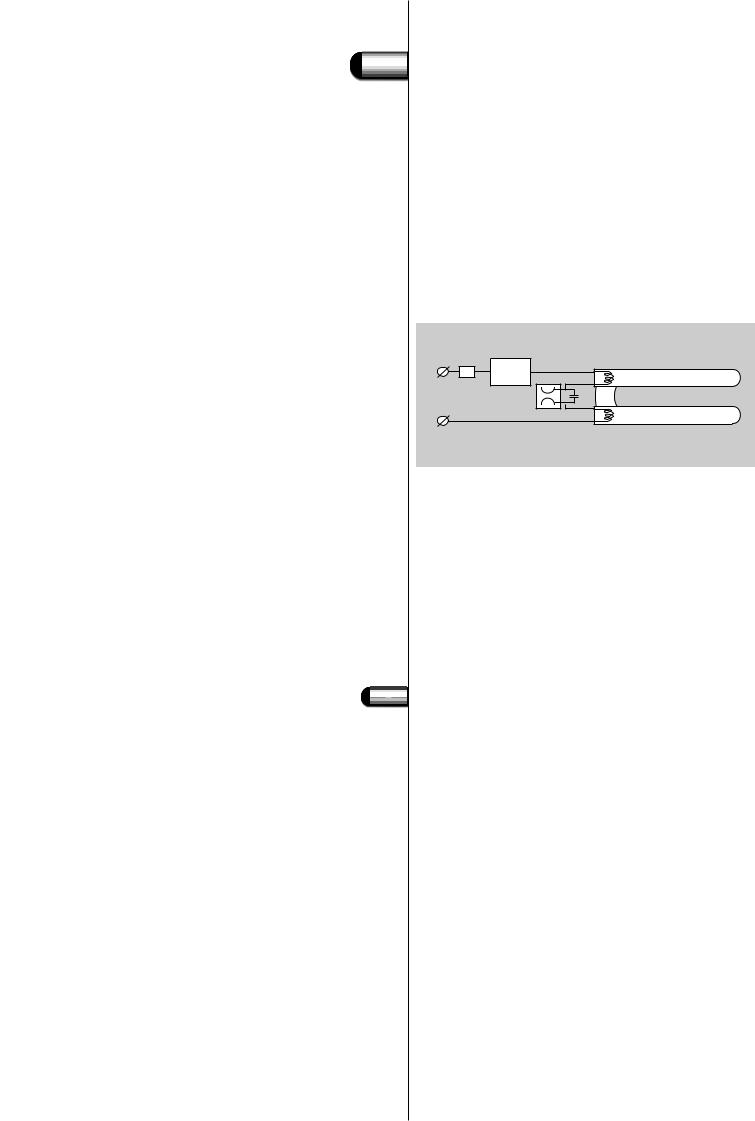
Fig. 109. Different ways of grouping capacitors to match them with the corresponding filter coil.


 3
3  4
4 
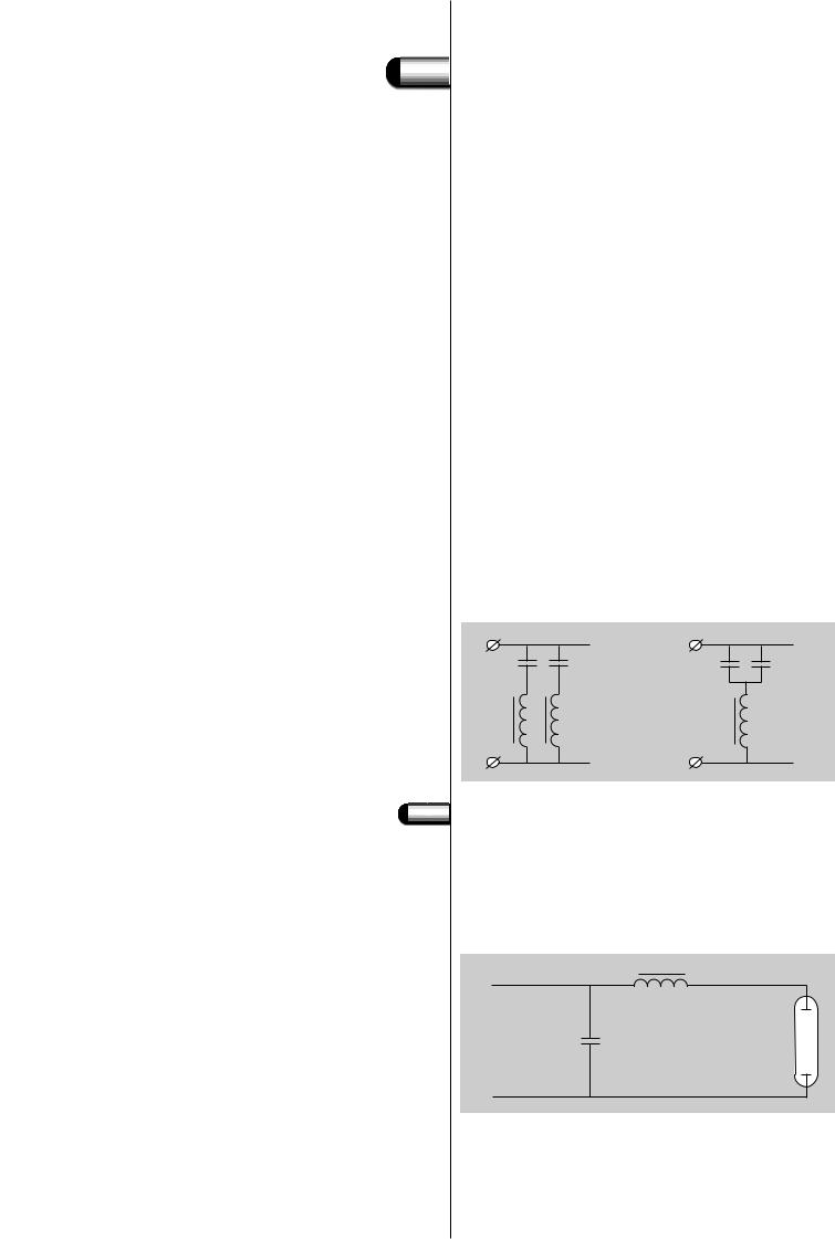
Fig. 110. Power factor correction with a parallel compensating capacitor.
3.3 Filter coils
There are other advantages to be gained from employing filter coils. The parallel capacitor can cause troublesome switching phenomena to occur, which can give rise to very large current surges.Although these surges are of only very short duration (a few milliseconds), they are nevertheless sufficient to cause switching relays to stick or circuit breakers to switch off.The filter coil serves to prevent this problem by damping the very short, high amplitude pulses in the current.
The type of filter coil needed depends on the capacitance of the capacitor employed. So, in fact every capacitor needs its own filter coil. But in some cases it is possible to group the capacitors and match them with the corresponding filter coil. For example: two capacitors of 4 µF parallel can be connected in series with one filter coil for 8 µF (see Fig. 109).
Also central filter coil systems exist where a filter system in the supply system is blocking the applied signalling frequencies.
Although the voltage across the filter coils is rather low (approx. 14 to 20 V), the filter coils have to be regarded as ballasts, as they are directly connected to the mains.They also cause some additional watt losses.
The amount of third and fifth harmonics in the mains current will rise in cases where the mains supply voltage is disturbed with third or fifth harmonics, when applying a filter coil.The total impedance for the combination of capacitor and filter coil is lower than the impedance of the sole capacitor for these frequencies (see section 5.3.9: Harmonic distortion and Fig. 108).
L |
|
L |
2 x 4 F |
= |
4 x 4 F |
capacitors |
capacitors |
|
2 x 4 F |
1 x 8 F |
|
coils |
|
filter coil |
N |
|
N |
Power factor correction
Circuits with gas-discharge lamps are stabilised with inductive ballasts and compensated for a good power factor with a parallel compensating capacitor (mono-compensation, Fig. 110).
Without the capacitor the inductive ballast causes a phase shift of the current, which is lagging behind the applied voltage.
B
L 
C
La
N 
119
 5
5
Fig. 111. Lamp current (Il), lamp voltage (Vl) and mains voltage (Vm).
Fig. 112. Example of a vector diagram showing lamp voltage and lamp current in phase.
Fig. 113. Uncompensated circuit with lamp current and mains voltage out of phase.
3.4 Power factor correction
Vm
I
 Vl
Vl
ϕ
This can be seen in Fig. 111, which is showing the lamp current Il, the lamp voltage Vl (both in phase with each other) and the sinus form of the mains voltage Vm.
The power factor of the circuit can be calculated by dividing the total wattage by the product of mains voltage and current. In formula:
P.F. = (Wl + Wb)/(Vm . Im) |
(1) |
Without the parallel compensating capacitor the power factor of a gas-discharge circuit is approx. 0.5.
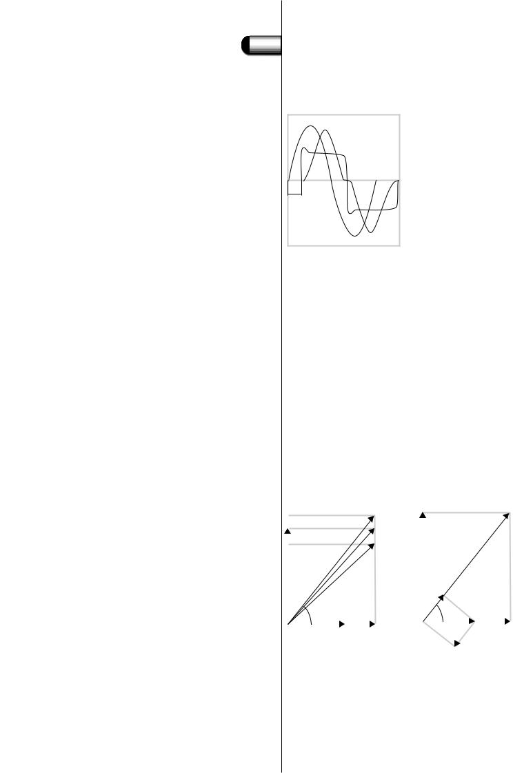
For the fundamentals of the voltages and current a so-called vector diagram can be made (see Fig. 112). Lamp voltage and lamp current are in phase and the voltage across the ballast is leading 90 electrical degrees to the current.The vectorial sum of lamp voltage and ballast voltage gives the mains voltage. Now we see that cos ϕ = Vl/Vm, which is less accurate than (1).
In any case the energy supply authority has to deliver an apparent power of Vm . Il to the system on which the distribution network must be based (cabling, transformers).
The energy meter only records the in-phase component Vm . Il cos ϕ, so the supply authority does not get paid for the so-called ‘blind’ part: Il sin ϕ .Vm (Fig. 113).
|
|
|
|
1.1 Vm |
Vb |
|
|
|
|
|
Vm |
|
|
|
|
|
|
|
|
||||
Vb |
|
|
|
Vm |
|
|
|
|
|
|
|
|
|
|
0.9 Vm |
|
|
|
|
|
|
|
|
|
|
|
|
|
|
|
|
|
|
|
|
ϕ |
|
|
|
|
|
|
Il cos |
ϕ |
|
|
|
|
|
|
|
|
|
|
|
ϕ |
|
|
|
|
|
|
|
|
|
|
|
|
|
||
|
|
|
|
|
|
|
|
|
|
|
|
|
|
|
|
|
|
|
|
|
Il |
Vl |
|
I |
l |
V |
l |
|
I |
sin |
|
||||
|
|
|
l |
j |
|
|
|||||
|
|
|
|
|
|
|
|
|
|||
|
|
|
|
|
|
|
|
|
|
||
For this reason, the supply authority demands compensation of the phase shift.
Where in general the ‘unadjusted’ power factor is about 0.50, it has to be compensated to a minimum of 0.85 or even 0.90.This is achieved by adding a capacitor across the mains. In contrast to an inductive
120
 5
5
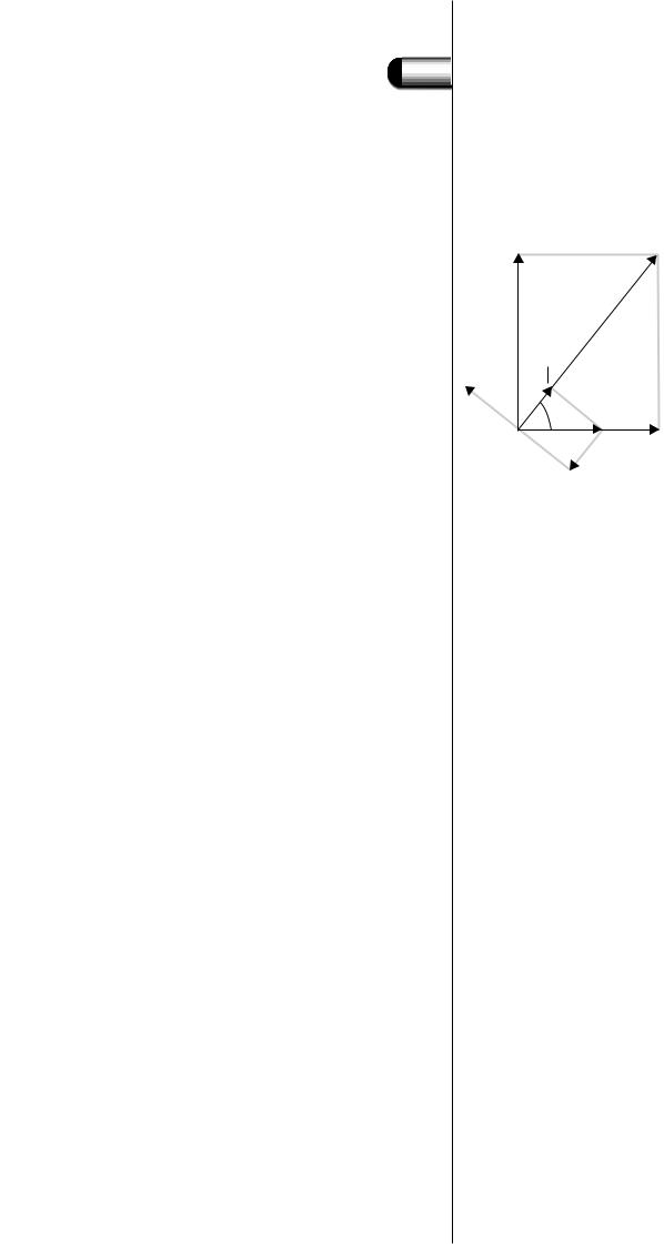
Fig. 114. Compensated circuit.
3.4 Power factor correction
ballast, the capacitor current is leading 90 electrical degrees to the capacitor voltage (which is the mains voltage). So the capacitor current has the opposite direction of Ilsin ϕ (see Fig. 114).
Vb |
Vm |
Il cos ϕ
I |
|
cap |
ϕ |
I |
Il |
Vl |
sin |
|
|
l |
|
|
ϕ |
|
|
|
|
Maximum compensation is achieved when the current through the capacitor Ic = Il sin ϕ ; then the power factor is 1.This is purely theoretical, as the vector diagram is only valid for the fundamentals of the currents. Due to distortion in the lamp current (see section 5.3.9: Harmonic distortion), the maximum practical power factor is between 0.95 and 0.98.This explains the difference between power factor and cos ϕ.
The power factor is the result of the quotient of the actual wattage and the product of mains voltage and mains current, including the harmonics, and can be calculated as follows:
Power factor (P.F.) = total wattage/mains voltage . mains current
The angle ϕ is the phase shift angle between mains voltage and mains current and can be found and calculated by means of the vector diagram.This is only valid for the fundamentals and does not take into account the harmonics.
The same analogy is valid for the lamp: there is practically no phase shift between lamp voltage and lamp current: both are zero at the same time. So the phase angle α is zero and cos α = 1.
The product of lamp voltage and lamp current does not equal the lamp wattage; the difference is called lamp factor:
Lamp factor = lamp wattage / lamp voltage . lamp current
and has a value between 0.8 and 0.9. For the same lamp type the lamp factor is higher for higher wattages, identical to the lamp efficacy. Typical capacitor values for this parallel compensation (also sometimes called mono-compensation) for a 50 Hz mains are 4.5 µF for a 36 or 40 W fluorescent lamp and 6.5 µF for a 58 or 65 W lamp.
A second method for compensation is the so-called duo-circuit.This is employed for pairs of lamps, as for example in two-lamp luminaires. Here the capacitor is placed in series with one of the ballasts (see Fig. 115).
121
 Loading...