


EDC-141E
Philips EDC-141E, EDC-142E, EDC-143E, EDC-142E1, EDC-144E User Manual
...
1
Installation and Operating Manual
Fastrax
Dome Video Camera for Ceiling and Wall Mounting
EDC-141E, EDC-142E, EDC-143E, EDC-142E1, EDC-144E, EDC-142E2

2
3
Contents
1. Introduction ..............................................................................................................................................................................................................3
1.1 Features ...................................................................................................................................................................................................................3
2. Installation and Conguration ................................................................................................................................................................................... 5
2.1 Package Contents..................................................................................................................................................................................................... 5
2.2 Basic Conguration of Fastrax II Dome Camera System ............................................................................................................................................ 6
2.2.1 Single Multiplexer..................................................................................................................................................................................................... 7
2.2.2 Single User with Two Multiplexer .............................................................................................................................................................................. 8
2.2.3 Two Multiplexer with Slave Keyboard Controller........................................................................................................................................................ 9
2.2.4 Two Multiplexer with Slave Keyboard Controller (method 2) .................................................................................................................................... 10
2.3 Setting Unit For Termination.................................................................................................................................................................................... 11
2.4 Setting Address (ID) of Dome Camera ....................................................................................................................................................................12
2.5 Setting Protocol of Dome Camera .......................................................................................................................................................................... 13
2.6 Connection ............................................................................................................................................................................................................ 14
2.7 Getting Started ....................................................................................................................................................................................................... 14
3. Program and Operation........................................................................................................................................................................................... 15
3.1 Selecting Dome Camera ......................................................................................................................................................................................... 15
3.2 Accessing On-Screen Menu Utility .......................................................................................................................................................................... 15
3.3 How To Control On-Screen Menu Utility................................................................................................................................................................... 15
3.4 Auto Scan............................................................................................................................................................................................................... 16
3.5 Preset..................................................................................................................................................................................................................... 17
3.6 Shortcut of Preset Program..................................................................................................................................................................................... 18
3.7 Tour ....................................................................................................................................................................................................................... 18
3.8 Pattern ................................................................................................................................................................................................................... 19
3.9 Alarm ..................................................................................................................................................................................................................... 20
3.10 Area Title............................................................................................................................................................................................................... 20
3.11 Privacy Zone........................................................................................................................................................................................................... 21
3.12 Camera ................................................................................................................................................................................................................. 22
Focus Control ......................................................................................................................................................................................................... 22
WB (White Balance) Control .................................................................................................................................................................................... 23
AE Control............................................................................................................................................................................................................... 24
Line Lock Control.................................................................................................................................................................................................... 25
Night Shot Menu..................................................................................................................................................................................................... 25
3.13 Dome Setup ........................................................................................................................................................................................................... 26
Language Setup ..................................................................................................................................................................................................... 26
Home Function Setup ............................................................................................................................................................................................. 26
OSD Display Setup.................................................................................................................................................................................................. 27
View Direction ........................................................................................................................................................................................................ 27
Dome OSD Display ................................................................................................................................................................................................. 27
Area Display ........................................................................................................................................................................................................... 27
Panning Range ....................................................................................................................................................................................................... 27
Flip ......................................................................................................................................................................................................................... 27
Tilt Over Angle ........................................................................................................................................................................................................ 28
Initialize Data.......................................................................................................................................................................................................... 28
Origin Offset ........................................................................................................................................................................................................... 28
Dome Reset............................................................................................................................................................................................................ 28
System Information ................................................................................................................................................................................................ 28
4. Troubleshooting...................................................................................................................................................................................................... 29
5. Glossary ................................................................................................................................................................................................................. 30
6. Short-Cut Key ......................................................................................................................................................................................................... 31
7. Specications ......................................................................................................................................................................................................... 32
8. Dimensional Drawings ............................................................................................................................................................................................ 34

3
Safety Instructions
• Read these safety instructions and the operation manual rst before you install and commission the camera.
• Keep the manual in a safe place for later reference.
• Protect your camera from contamination with water and humidity to prevent it from permanent damage. Never switch the camera on when it gets wet.
Have it checked at an authorized service center in this case.
• Never operate the camera outside of the specications as this may prevent the camera functioning.
• Do not operate the cameras beyond their specied temperature, humidity or power ratings. Operate the camera only at a temperature range of -10°C to
+50°C and at a humidity of max. 90%.
• To disconnect the power cord of the unit, pull it out by the plug. Never pull the cord itself.
• Pay attention when laying the connection cable and observe that the cable is not subject to heavy loads, kinks, or damage and no moisture can get in.
Do not attempt to disassemble the camera board from the dome.
• Do not attempt to disassemble the camera board from the dome.
• The warranty becomes void if repairs are undertaken by unauthorized persons. Do not open the camera housing. Maintenance and repair have to be
carried out only by authorized service centers.
• Do not use strong or abrasive detergents when cleaning the dome. Use a dry cloth to clean the dome surface. In case the dirt is hard to remove, use a mild
detergent and wipe gently.
NOTE: This is a class A digital device. This digital device can cause harmful interference in a residential area; in this case the user may be required
to take appropriate corrective action at his/her own expense.
1. Introduction
1.1 Features
The Fastrax II Keyboard Controller and the Fastrax II dome cameras make up the building blocks for any surveillance/security system. Using multiple Keyboard
Controllers and multiple dome cameras, no place is too large for monitoring. Extensible and exible architecture facilitates remote control functions for a
variety of external switching devices such as multiplexers and DVRs.
• Built-in 18x (23x,25x, 22x, 26x) times optical power zoom camera with True Night Shot function
• 240 Preset positions
• 8 Tours consist of Preset, Pattern, Auto-Scan and Tour itself can be programmed over 300 functions and Preset location. While moving, each Preset scan
can be watched in smooth Vector Scan mode.
• 8 Auto Scan including vector scan (and 1 endless Auto Scan at EDC-144E)
• 4 Pattern (240seconds)
• 8 Privacy zone
• 8 Alarm input / 4 Aux out (NC & NO)
• Variable speed from 0.1°/sec to 90°/sec
• Turbo speed is Max 360°/sec with Ctrl key pressed
• Maximum speed is inversely proportional to the zoom ratio
• Maximum speed is 380°/sec when preset command.
• Programmable user preferences (alarm, preset, title, etc.)
• Up to 999 selectable camera addresses
• Built-in RS-485/422 receiver driver
• Clear bubble with black liner (shelter) for concealing the camera
• Optional Tinted Bubble, Indoor & Outdoor pendant housing with heater & blower, Indoor Flush Mount, Parapet mount & Roof Top mount

4
5
Figure 1 - Typical System Conguration
Figure 2 - Assemble bubble ring ass’y
Note: It is recommended to remove camera window for improving picture quality when you assemble bubble ring ass’y.
up to 255 multiplexer
Alarm Input
(up to 8)
<Sensor>
<Siren>
<Flashing light>
Alarm
Output
(up to 4)
J-box
Master keyboard
up to 3 Slave keyboards
up to 99 DVR
up to 32 cameras
push
push
remove
camera window
bubble ring ass’y
screw
Remove window Assemble bubble ring ass’y

5
2. Installation and Conguration
2.1 Package Contents
The package contains the following:
1x Fastrax II E (Dome Camera)
1x Bubble Ring
1x Instruction Manual (This Document)
3x Assembly Screws for Attaching Fastrax II E
3x Plastic Anchor
1x 10Pin Connector
2x 12Pin Connector
CAUTION: Be sure to have caution labels (E version only) on both body and base of the camera.
Different version will not support alarm input and output.
The dome camera is for use in surface mounting applications and the mounting surface should be capable of supporting loads up to 10lb (4.5kg).
The dome camera’s base should be attached to a structural object, such as a hard wood, wall stud or ceiling rafter that supports the weight of the dome
camera.
Figure 3 - Installation
Cable entry
Surface (ceiling)
Base
Align extruded tap in the base to
the keyhole on the PCB in the body
Body
LockUnlock
Lock
6
7
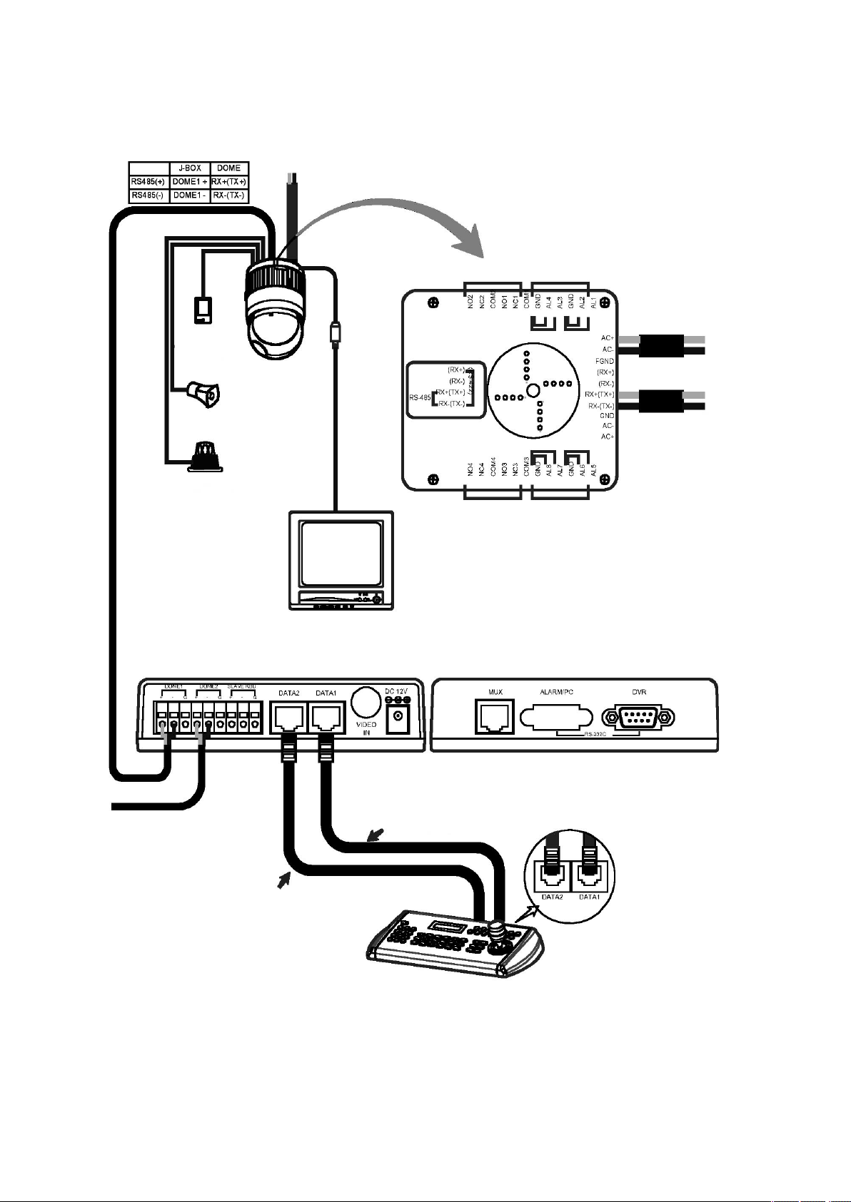
2.2 Basic Conguration of Fastrax II Dome Camera System
Figure 4- Basic installation diagram
The dome camera must be installed by qualied service personnel in accordance with all local and federal electrical and building codes.
The system should be installed according to Figures 4 through 9.
Power
24VAC
STP AWG #24
Sensor
Alarm input
up to 8
Siren
Light
Alarm output
up to 4
BNC
Alarm output
1 ~ 2
Alarm input
1 ~ 4
Power
24VAC
Dome1+
Dome1–
Alarm output
3 ~ 4
Alarm input
5 ~ 8
Monitor
BNC
RS-485
Half Duplex mode: RX+, RX–
RS-422
Simplex mode: (RX+), (RX–)
Duplex mode: (TX+), (TX–), (RX+), (RX–)
J-Box (Back) J-Box (Front)
unshielded cable
unshielded cable
DATA2 port should be connected
in case that DOME2 port or DVR
port are used.
Up to 128 Dome cameras including
32 alarm mode can be connected
at DOME2 port.
Rear
Keyboard controller
7
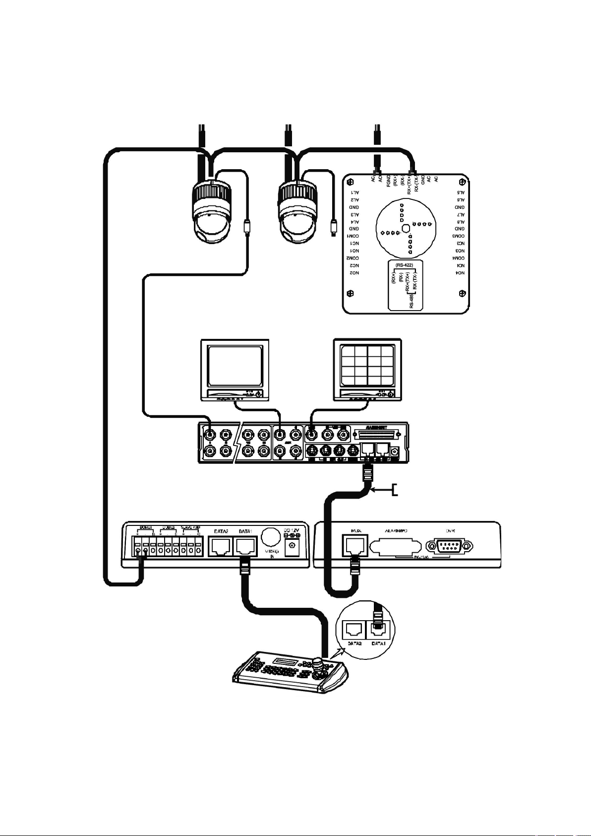
2.2.1 Single Multiplexer
Figure 5 - Single Multiplexer
Rear
Keyboard controller
Power
24VAC
BNC
Main Monitor
BNC
BNC
RS-485 (–) Pin No. 4
RS-485 (+) Pin No. 6
J-Box (Back) J-Box (Front)
AWG #24
Power
24VAC
Power
24VAC
Spot Monitor
Multiplexer
8
9
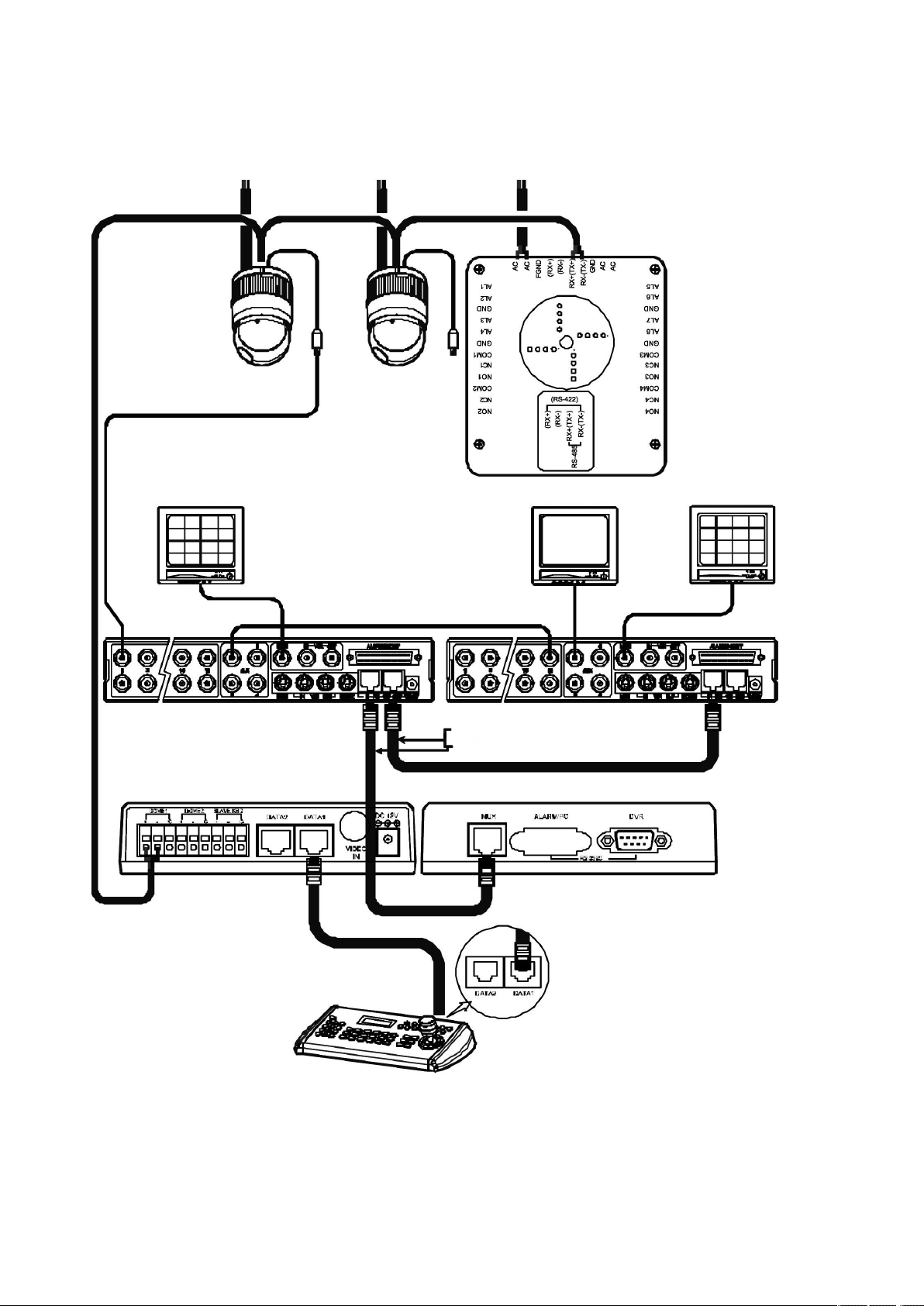
2.2.2 Single User with Two Multiplexer
Figure 6 - Two Multiplexer
Rear
Keyboard controller
Power
24VAC
BNC
1st Main Monitor
BNC
BNC
RS-485 (–) Pin No. 4
RS-485 (+) Pin No. 6
J-Box (Back) J-Box (Front)
AWG #24
Power
24VAC
Power
24VAC
Spot Monitor
1st Multiplexer
BNC
2nd Multiplexer
2nd Main Monitor
Spot output of the rst multiplexer to be connected
to 16
th
input of the second multiplexer.
And rst spot output of the 2
nd
multiplexer to be
connected to the spot monitor. You will see tthe
picture of the selected camera (1-31) on spot
monitor by selecting camera No. + Cam.
9
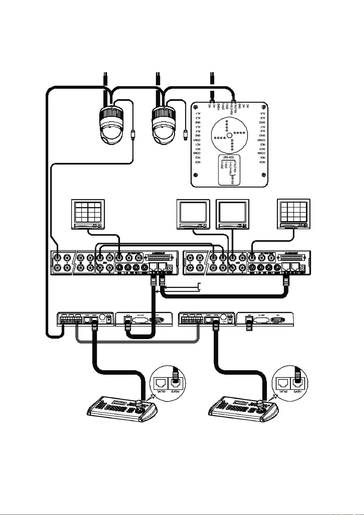
2.2.3 Two Multiplexer with Slave Keyboard Controller
Figure 7 - Two Multiplexer with Slave Keyboard Controller
Rear
Keyboard controller
Master
Power
24VAC
BNC
1st Main Monitor
BNC
BNC
RS-485 (–) Pin No. 4
RS-485 (+) Pin No. 6
J-Box (Back) J-Box (Front)
AWG #24
Power
24VAC
Power
24VAC
Spot Monitor
for Master K/B
1st Multiplexer
BNC
2nd Multiplexer
2nd Main Monitor
Spot Monitor
for Slave K/B
Keyboard controller
Slave
Rear
Spot output 1 of the rst multiplexer to be connected to 16
th
input of the
second multiplexer.
n: User, Spot out of n
th
to be connected to (17-n)
th
camera input of the 2
nd
multiplexer. n
th
spot out of the 2
nd
multiplexer to be connected to the n
th
spot
monitor. Each user will see the picture of the selected camera (1 ~ (31-n)) on
n
th
spot monitor of the Mux 2 by selecting camera No. + Cam.
10
11
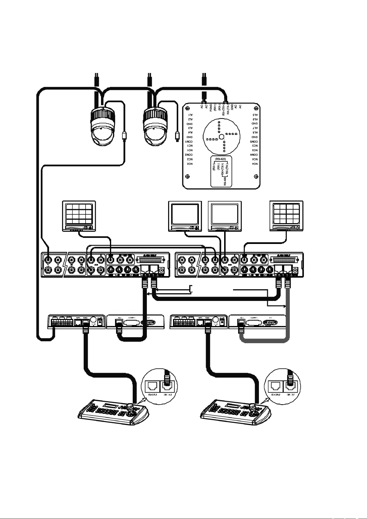
2.2.4 Two Multiplexer with Slave Keyboard Controller (method 2)
Figure 8 - Two Multiplexer with Slave Keyboard Controller (method 2)
Spot output 1 of the rst multiplexer to be connected to 16
th
input of the
second multiplexer.
n: User, Spot out of n
th
to be connected to (17-n)
th
camera input of the 2
nd
multiplexer. n
th
spot out of the 2
nd
multiplexer to be connected to the n
th
spot
monitor. Each user will see the picture of the selected camera (1 ~ (31-n)) on
n
th
spot monitor of the Mux 2 by selecting camera No. + Cam.
Rear
Keyboard controller
Master
Power
24VAC
BNC
1st Main Monitor
BNC
BNC
RS-485 (–) Pin No. 4
RS-485 (+) Pin No. 6
J-Box (Back) J-Box (Front)
AWG #24
Power
24VAC
Power
24VAC
Spot Monitor
for Master K/B
1st Multiplexer
BNC
2nd Multiplexer
2nd Main Monitor
Spot Monitor
for Slave K/B
Keyboard controller
Slave
Rear

11
Figure 9 - Layout of Switches
2.3 Setting Unit for Termination
The device which is connected at end of line, whether it is a dome camera or keyboard controller, must have the cable for communication terminated by
setting the appropriate DIP switch. Without proper termination, there is potential for control signal errors. Total length of the cable for communication should
not exceed 1.2km.
SW1 1 2
Terminated ON ON
Not terminated OFF OFF
Figure 10 - Setting Unit for Termination
Termination switches
Addresses (ID) and protocol
selection switches
 Loading...