


WS-1612
PROFESSIONAL WEATHER CENTER
WS-1612
Operation Manual

Table of Contents
Topic Page
Features 3
Setting up 6
Function keys 12
LCD Screen 14
Manual Setting 16
Time alarm setting 24
Weather alarm operations 25
Hysteresis 31
Weather forecast and weather tendency 32
Wind direction and wind speed measurement 36
Rainfall measurement 37
Viewing history data 37
Viewing the min/ max weather data 39
Switch On/ Off buzzer 46
Outdoor transmission 915 MHz reception 48
Positioning 49
Care and Maintenance 53
Specification 54
Warranty Info 57
1

PROFESSIONAL WEATHER CENTER
Instruction Manual
Congratulations on purchasing this state-of-the-art Professional Weather Center as an
example of excellent design and innovative technology. Featuring time, date,
calendar, weather forecast, wind direction and speed, rainfall, outdoor temperature
and outdoor humidity, air pressure and various alarm settings for different weather
conditions, this Weather Center will provide you with extensive weather information
and forecast.
This product offers:
INSTANT TRANSMISSION is the
state-of-the-art new wireless
transmission technology, exclusively
designed and developed by LA
CROSSE TECHNOLOGY. INSTANT
TRANSMISSION
immediate update (every 4.5
seconds!) of all your outdoor data
measured from the sensors: follow
your climatic variations in real-time!
offers you an
2
FEATURES:
Weather Center
LCD
•
Time display (manual setting)
•
12/24 hour time display
•
Calendar display (weekday, date, month, year)
•
Time alarm function
•
Weather forecasting function with 3 weather icons and weather tendency
indicator
•
Outdoor temperature display in ºF/°C
•
Outdoor Humidity display as RH%
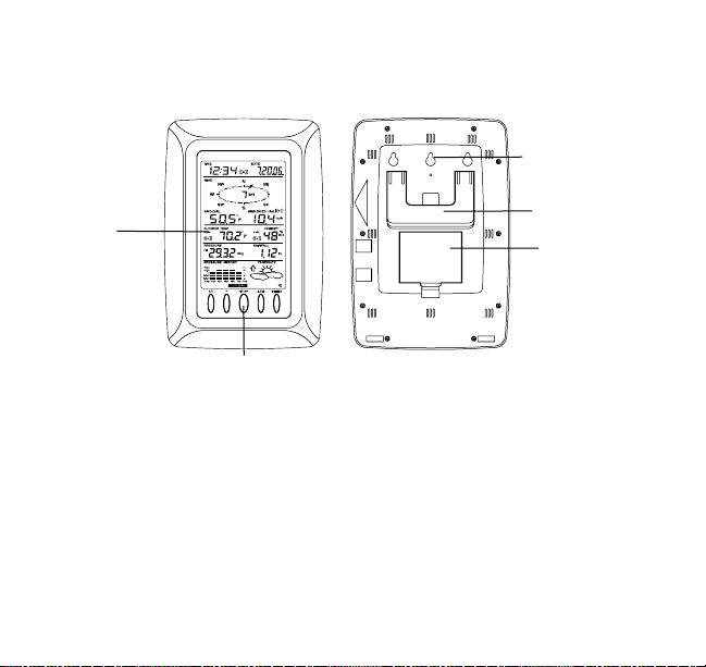
Function keys
Hanging hole
Foldout stand
Battery
compartment
cover
3
•
MIN/MAX value of outdoor temperature and humidity display with time & date
of recording
•
Low/High outdoor temperature and humidity alarm
•
Relative air pressure displayed in inHg or hPa
•
Air pressure tendency indicator for the past 12 hours (bargraph format)
•
LCD contrast selectable
•
Low battery indicator
•
Wind direction displayed in 16 steps
•
Wind speed displayed in mph, km/h, or m/s, and Beaufort scale
•
Wind chill displayed in °F of °C
•
Max wind speed displayed with time & date of recording
•
High alarm function for wind speed
•
Manual reset of outdoor temperature/ humidity, pressure and wind chill data
•
Total rainfall displayed in mm or inch
•
Storm warning alarm
•
Buzzer on/off selectable
•
Storage of 200 sets of history weather data recorded in 3-hour intervals
•
Wireless transmission at 915 MHz
•
Transmission range up to 330 feet (100 meters)
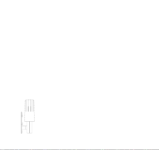
Thermo-hygro Sensor
•
Remote transmission of the outdoor temperature and humidity
to the Weather Center at 915 MHz
•
Weather-resistant casing
•
Wall mounting case (to be mounted in a sheltered place. Avoid
direct rain and sunshine)
4
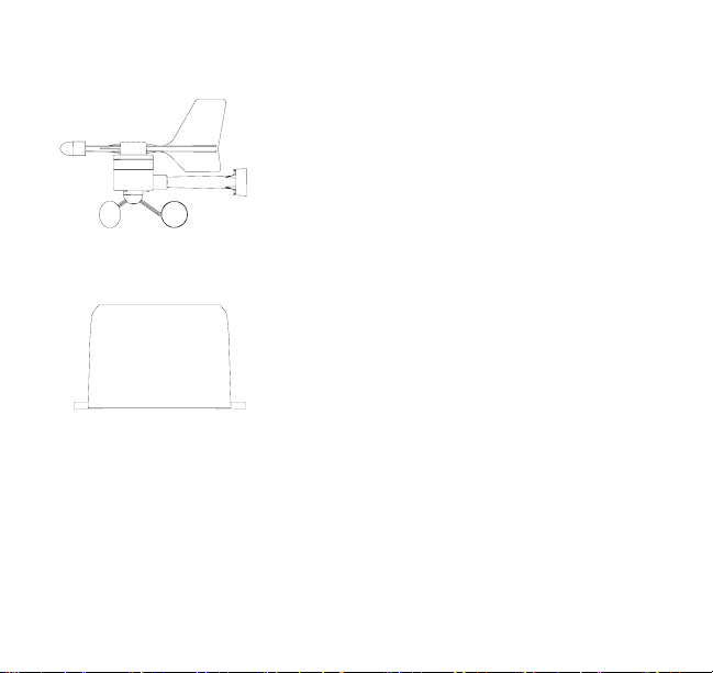
Wind Sensor
Rain Sensor
•
Connected to the thermo-hygro sensor by cable
•
Can be installed onto a mast or a horizontal panel
•
Connected to the thermo-hygro sensor by cable
•
To be mounted onto a horizontal panel
5
r
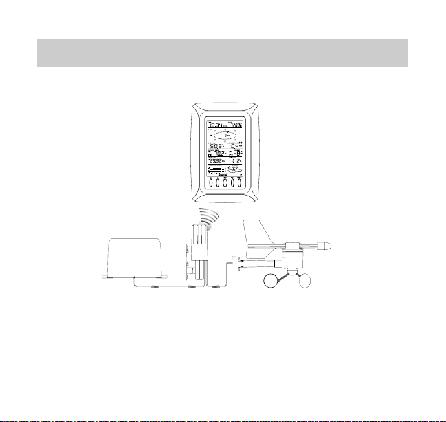
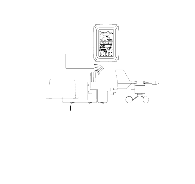
SETTING UP:
Wireless transmission at
915 MHz - thermo-hygro
Note:
When putting the Weather Center into operation, it is important to perform in close
proximity (e.g. on a table) a complete wiring and set-up of the system. This step is
sensor to the Weather
Rain Senso
Center
Cable connection between
the rain sensor and the
thermo-hygro sensor
Weather Center
Cable connection between
the wind sensor and the
thermo-hygro sensor
Wind Sensor
6
important to test all components for correct function before placing and mounting them
at their final destinations (See Positioning below)
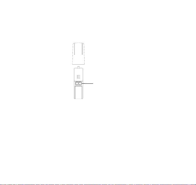
1. Unwind the cables of the rain and the wind sensors. Connect the rain and the
wind sensors to the thermo-hygro sensor by plugging the connector heads of
the two sensors into the appropriate sockets of the thermo-hygro sensor.
Sockets for wind
and rain sensor
2. First insert the batteries into the thermo-hygro sensor (see “How to install and
replace the batteries into the thermo-hygro sensor“ below).
3. Then insert the batteries into the Weather Center (see “How to install and
replace the batteries into the Weather Center” below). Once the batteries
are installed, all segments of the LCD will light up briefly and a short signal
tone will be heard. It will then display the time as 12:00, the date as 1.1.05, the
weather icons, and air pressure value. "- - -" will be shown for outdoor data.
4. Afterwards, the Weather Center will start receiving data from the sensor. The
outdoor temperature, humidity wind chill and wind speed should then be
7

displayed on the Weather Center. If this does not happen after 30 seconds, the
batteries will need to be removed from both units. You will have to start again
from step 1.
5. You may then check all cables for correct connection and all components for
correct function by manually turning the wind-gauge, moving the weather-vane,
tilting the rain sensor to hear the impact of the internally moving seesaw, etc
(See Positioning below).
6. Time and date shall be manually set (See Manual Setting below).
7. After the Weather Center has been checked for correct function with regard to
the above points and found fit, the initial set up of the Weather Center system
is finished and the mounting of the system components can take place. It must
be verified, however, that all components work properly together at their
chosen mounting or standing locations. If e.g. there appear to be problems with
the 915 MHz radio transmission, they can mostly be overcome by slightly
changing the mounting locations.
Note:
The radio communication between the receiver and the sensor in the open field
reaches distances of max 330 feet, provided there are no interfering obstacles such
as buildings, trees, vehicles, high voltage lines, etc.
8. Radio interferences created by PC screens, radios or TV sets can in some
cases entirely cut off radio communication. Please take this into consideration
when choosing standing or mounting locations.
Note:
The thermo-hygro sensor should be placed in a dry, shaded area. The temperature
sensor has a range of 330 feet. Keep in mind that the 330 feet is in open air with no
8

obstructions and that radio waves DO NOT curve around objects. Actual transmission
range will vary depending on what is in the path of the signal. Each obstruction (roof,
walls, floors, ceilings, thick trees, etc.) will effectively cut signal range in half.
Example: A Professional Weather Center with a 330 feet range is mounted on an
interior wall, so that the signal has to pass through one interior wall, one exterior wall,
and across the 10 feet width of the room between the 2 walls. The first wall will
reduce the range to 165 feet, and the second wall will reduce the range to 87 feet.
Factoring in the 10 foot room, this leaves a maximum of 77 feet of remaining signal
range.
This allowance is typically enough for a frame wall with non-metallic siding; however
certain materials can reduce range even further. Metal siding, stucco, and some
types of glass can reduce signal range by as much as ¾ or more, compared to the ½
reduction typical of most obstructions. It is possible to receive a signal through these
materials, however maximum range will be much less due to their tendency to absorb
or reflect a much larger portion of the sensor’s signal
.
Note :
•
After batteries are installed in the sensor, install the batteries in the Weather
Center to receive the signal from the sensor as soon as possible. If the
Weather Center is powered more than 5 hours after the sensor is powered, the
Weather Center will never receive signal successfully from this sensor. In this
case, user will need to reinstall the batteries from the sensor to redo set-up
procedure.
9
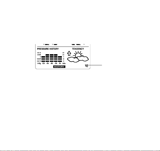
•
After batteries are installed, there w ill be sy nchronization between Weather
Center and the sensor. At this time, the signal reception icon will be blinking.
When the signal is successfully received by the Weather Center, the icon will
be switched on. (If it is not successful, the icon will not be shown in LCD) So
the user can easily see whether the last reception was successful (icon on) or
not (icon off). On the other hand, the short blinking of the icon shows that a
reception is in progress.
•
If the signal reception is not successful on the first frequency (915MHz) for 14
Sensor signal reception
icon
seconds, the frequency is changed to 920MHz and the learning is tried another
14 seconds. If still not successful the reception is tried for 14 seconds on
910MHz. This will also be done for re-synchronization.
HOW TO INSTALL AND REPLACE THE BATTERIES INTO THE WEATHER
CENTER
The Weather Center works with 3 x AA, IEC LR6, 1.5V batteries. When the batteries
need to be replaced, the low battery symbol will appear on the LCD.
To install and replace the batteries, please follow the steps below:
10
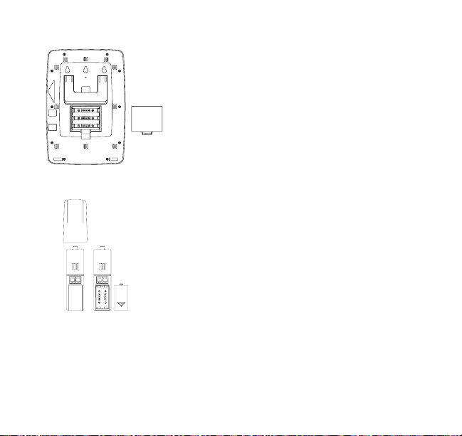
1. Remove the battery compartment cover.
2. Insert the batteries observing the correct
polarity (see the marking in the battery
compartment).
3. Replace the battery cover.
HOW TO INSTALL AND REPLACE THE
BATTERIES INTO THE THERMO-HYGRO SENSOR
The outdoor thermo-hygro sensor works with 2 x “AA”,
IEC LR6 1.5V batteries. To install and replace the
batteries, please follow the steps below:
1. Uninstall the rain cover of the sensor.
2. Remover the battery compartment cover.
3. Insert the batteries, observing the correct polarity (see
the marking in the battery compartment).
4. Replace the battery cover and the rain cover onto the
unit.
11
Note:
In the event of changing batteries in any of the units, all units need to be reset by
following the setting up procedures. This is because a random security code is
assigned by the thermo-hygro sensor at start-up and this code must be received and
stored by the Weather Center in the first 30 seconds of power being supplied to it.
BATTERY CHANGE:
It is recommended to replace the batteries in all units every 24 months to ensure
optimum accuracy of these units.
Note:
The stored History record will not be kept after the battery change is done on the
Weather Center.
Please participate in the preservation of the environment. Return
used batteries to an authorized depot.
12
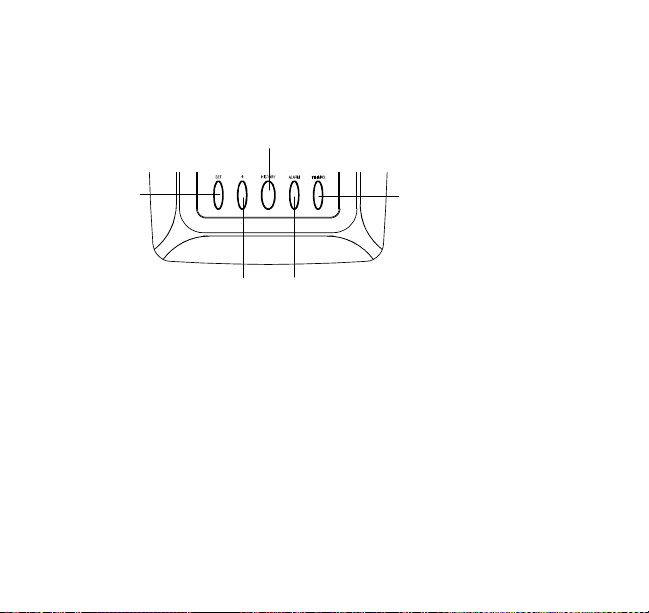
FUNCTION KEYS:
A
Weather Center:
The Weather Center has 5 easy-to-use function keys.
Set key
SET key
•
Press to enter manual setting modes: LCD contrast, Manual time setting, 12/24
hour time display, Calendar setting, ºF/ºC temperature unit, Wind speed unit,
Rainfall unit, Pressure unit, Relative pressure reference setting, Weather
Tendency Sensitivity Value setting, Storm warning sensitivity setting and Storm
Alarm On/Off setting
•
In normal display mode, press and hold to switch on/off the Buzzer
•
In the weather alarm setting mode, press and hold to adjust different alarm
value and switch the alarm On/Off
•
Press to activate the reset mode when max or min record is shown
•
Stop the alarm during the time alarm or weather alarm ringing
•
To switch on the backlight
HISTORY key
+ key
MIN/MAX key
LARM key
13

+ key
•
Press to change the calendar display to the preset alarm time, date, weekday +
date or seconds in the time display
•
Press to adjust (increase) the level of different settings
•
Stop the alarm during the time alarm or weather alarm ringing
•
Press to confirm to reset the max/min record
•
To switch on the backlight
HISTORY key
•
Press to display the weather data history records
•
Stop the alarm during the time alarm or weather alarm ringing
•
Press to exit manual setting mode and alarm setting mode
•
To switch on the backlight
ALARM key
•
Press to enter the time alarm and weather alarm setting mode
•
Confirm particular alarm setting
•
Press to exit the manual setting mode
•
Stop the alarm during the time alarm or weather alarm ringing
•
Press to exit max/ min record display mode
•
To switch on the backlight
MIN/MAX key
•
Press to display minimum and maximum records of various weather data
•
Press to adjust (decrease) the level of different settings
•
Stop the alarm during the time alarm or weather alarm ringing
•
To switch on the backlight
14

Note:
The LED backlight will be on and last for 15 seconds for every simple key-
press. The LED will keep lighting when the key is "pressed and held".
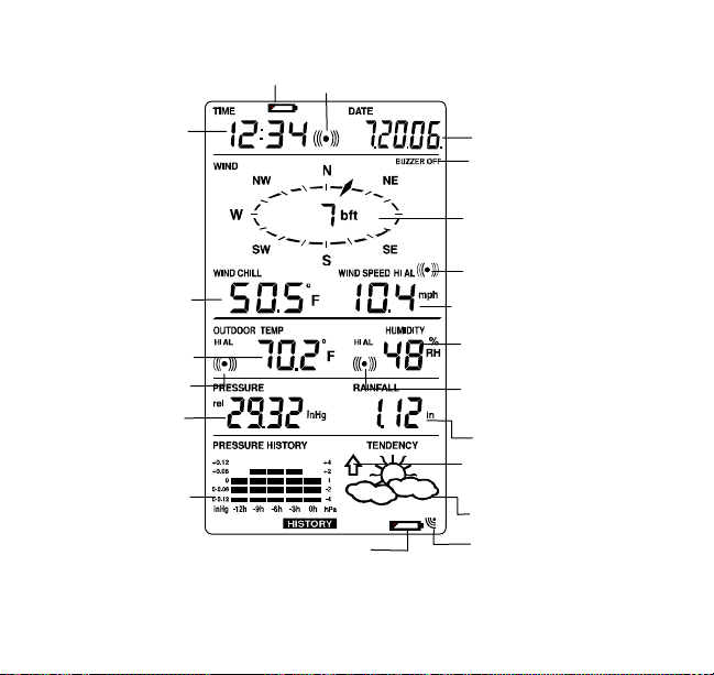
LCD SCREEN
The LCD screen is split into 5 sections displaying the following information:
1. Time and date
2. Wind data
3. Outdoor temperature and humidity,
4. Air pressure and Rainfall data
5. Air pressure history and Weather forecast.
15
X
Time display
Wind Chill in °F or °C
Outdoor temperature
display in inHg or hPa
in °F or ºC
Outdoor temp.
alarm icon
Relative air pressure
Air pressure
histogram
Low battery
indicator
Sensor low battery
Time alarm icon
indicator
16
Wind speed in mph, km/h
or m/s
Outdoor relative
humidity in %
Outdoor Humidity
alarm icon
Weather tendency
indicator
T
Calendar display
Buzzer off indicator
Wind direction display and
wind speed in Beaufort
scale
Wind speed Hi/ Lo alarm
icon
Total rainfall in inch or mm
Weather forecast
icon
Sensor signal reception
icon

MANUAL SETTING:
The following manual settings can be changed once the SET key is pressed:
•
LCD contrast setting
•
Manual time setting
•
12/24 hour time display
•
Calendar setting
•
°F/ °C temperature unit setting
•
Wind speed unit
•
Rainfall unit setting
•
Air pressure unit setting
•
Relative pressure reference value setting
•
Weather Tendency Sensitivity value
•
Storm warning threshold value
•
Alarm On/ Off setting
LCD CONTRAST SETTING
The LCD contrast can be set within 8 levels, from "LCD 1" to "LCD8" (default setting is
LCD 5):
1. Press the SET key, the contrast level digit will start flashing.
2. Use the + or MIN/MAX key to adjust the level of contrast.
3. Confirm with the SET key and enter the MANUAL TIME SETTING.
Digit flashing
17
MANUAL TIME SETTING:
r
You then may manually set the time of the clock by following the steps below:
Minutes flashing
Hou
flashing
1. The hour digit will start flashing.
2. Use the + or MIN/MAX key to set the hour.
3. Press the SET key to switch to the minutes. The minute digit will start flashing.
4. Use the + or MIN/MAX key to set the minute.
5. Confirm the time with the SET key and enter the 12/24 HOUR TIME DISPLAY
SETTING.
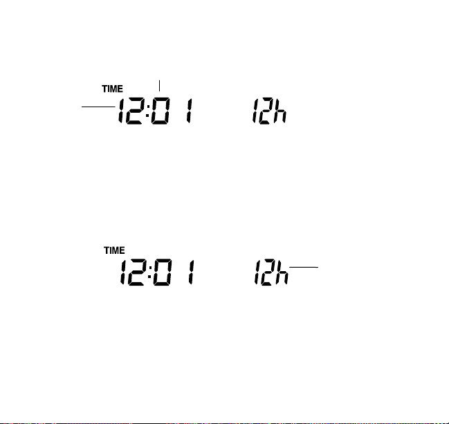
12/24 HOUR TIME DISPLAY SETTING:
Digit flashing
The time can be set to view as 12-hour or 24-hour format. The default time display
mode is 12-h. To set to 24-h time display:
1. Use the + or MIN/MAX key to toggle the value.
18
 Loading...