


WS-8025SU
R
Wireless Weather Center with
Sun/Moon Time
Instruction Manual
RADIO CONTROLLED
TIME DATE
WWWB
SUNRISE MOON PHASE
PM PM
SUNSET
INDOOR TEMPERATURE
TENDENCY
PRESSURE
rel
PRESSURE HISTORY
OUTDOOR TEMPERATURE
LO
MINHIMAX
MOONRISE +1
LOCATION MOONSET
HUMIDITY
inHg
-1h-3h-6h-9h-12h-18h-24h-30h
+1
+0.5
+0.2
0
HUMIDITY
2
%RH%
MIN MAX
%
RH
+7
+5
+3
+1
0
-1
-3
-5
-7
01
+4
+2
%
RH
RH
FCC ID: OMO-01TX (transmitter), OMO-01RX (receiver)
THIS DEVICE COMPLIES WITH PART 15 OF THE FCC RULES. OPERATION IS SUBJECT TO
THE FOLLOWING TWO CONDITIONS:
1. THIS DEVICE MAY NOT CAUSE HARMFUL INTERFERENCE, AND
2. THIS DEVICE MUST ACCEPT INTERFERENCE RECEIVED, INCLUDING INTERFERENCE
THAT MAY CAUSE UNDESIRED OPERATION.
OUT
ALARM
SET
IN
SUN/
MOON
CH
+
–
REMOTE
THERMO-SENSOR
433 MHz

Contents
Language Page
English 2
French 22
Spanish 44
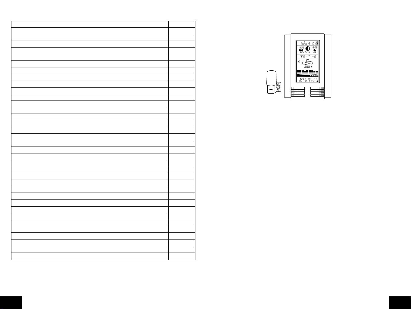
TABLE OF CONTENTS
Topic Page
Inventory of Contents/ Additional Equipment 3
About WWVB 3
Quick Set Up Guide 3
Detailed Set Up Guide
Battery Installation 4
Start Up Sequence 5
Explanation of LCD Information 6
Function Key Layout 6
Program Mode
Time, 12/24 Hour Mode and Date Setting 7
City Location Setting 7
U.S. City Codes 8
Canada City Codes 11
Mexico City Codes 11
Time Zone and Daylight Saving Time (DST) Setting 11
Weather Measuring Units 11
LCD Contrast 12
Features and Operation
Sun Rise/Set and Moon Rise/Set Calculation 12
Moon Phase 13
Minimum/Maximum Temperature/Humidity 14
Multiple Remote Transmitters 14
Remote T emperature Alarm 15
Comfort Indicator 15
Weather Forecast Icon and Pressure Trend 15
Weather Tendency Arrows 16
Storm Warning Alarm 16
Two Hour Air Pressure Tendency Chart 17
Barometric Air Pressure Reading 17
Air Pressure History Bar Chart 17
Mounting 17
Maintenance and Care 19
Troubleshooting Guide 19
Specifications 19
Warranty Information 20
INVENTORY OF CONTENTS
1. WS-8025SU-indoor weather station
2. TX4U-remote thermo/hygro (temperature/humidity) sensor
3. Instruction manual and warranty card
RADIO CONTROLLED
TIME DATE
WWWB
MOONRISE +1
SUNRISE MOON PHASE
PM PM
LOCATION MOONSET
SUNSET
HUMIDITY
INDOOR TEMPERATURE
TENDENCY
PRESSURE
PRESSURE HISTORY
OUTDOOR TEMPERATURE
LO
6
REMOTE
THERMO-SENSOR
433 MHz
MINHIMAX
%
RH
rel
inHg
+7
+5
+3
+1
0
-1
-3
-5
-7
-1h-3h-6h-9h-12h-18h-24h-30h
01
+4
+2
+1
+0.5
+0.2
0
HUMIDITY
%
2
RH
%RH%
RH
MIN MAX
SUN/
IN
MOON
OUT
CH
ALARM
+
SET
–
ADDITIONAL EQUIPMENT (not included)
1. Five fresh AA 1.5V alkaline batteries.
2. One wall-mounting screw (optional)
ABOUT WWVB (radio-controlled time)
The NIST (National Institute of Standards and Technology-Time and F requency Division) radio station,
WWVB, is located in Ft. Collins, Colorado and transmits the exact time signal continuously throughout
the United States at 60 kHz. The signal can be received up to 2,000 miles away through the internal
antenna in the indoor weather station. However, due to the nature of the Earth's Ionosphere, reception
is very limited during daylight hours. The indoor weather station will search for a signal every night
when reception is best. The WWVB radio station derives its signal from the NIST Atomic clock in
Boulder, Colorado. A team of atomic physicists continually measure every second of every day to an
accuracy of ten billionths of a second a day. These physicists hav e created an international standard,
measuring a second as 9,192,631,770 vibrations of a Cesium 133 atom in a vacuum. For more
information about WWVB please see the NIST website at
http://www.boulder.nist.gov/timefreq/stations/wwvb.htm
QUICK SET-UP GUIDE
Hint : Use good quality Alkaline Batteries and avoid rechargeable batteries.
1. Have the indoor weather station and remote thermo/hygro sensor 3 to 5 apart.
2. Batteries should be out of both units for 10 minutes.
3. Place the batteries into the remote thermo/hygro sensor first then into the indoor weather station.
(All remote thermo/hygro sensors must be started before the indoor weather station)
4. DO NOT PRESS ANY BUTTONS FOR 10 MINUTES.
In this time the indoor weather station and remote thermo/hygro sensor will start to talk to each other
and the indoor weather station will show both the indoor temperature and humidity and the outdoor
temperature and humidity. If the indoor weather station does not display all values after the 10
minutes please retry the set up as stated above. After all values are displayed f or 10 minutes y ou can
place your remote thermo/hygro sensor outdoors and set your time.
GB
P.2
The remote thermo/hygro sensor should be placed in a dry, shaded area. The remote thermo/hygro
sensor has a range of 200 feet. An y w alls that the signal will hav e to pass through will reduce distance.
An outdoor wall or window will have 20 to 30 f eet of resistance and an interior wall will have 10 to 20
feet of resistance. Your distance plus resistance should not exceed 200 ft. in a straight line.
P.3
GB

NOTE
: Fog and mist will not harm your remote thermo/h ygro sensor but direct rain must be avoided.
II. Start Up Sequence
To complete the set up of your indoor weather station after the 10 minutes ha v e passed please follow
the steps in the Detailed Set Up Guide.
Note
: The remote thermo/hygro sensor transmits a signal every 5 minutes; after the batteries have
been installed, the indoor weather station will search for the signal for a duration of 5 minutes. If there
is no temperature reading in the OUTDOOR LCD after 5 minutes, make sure the units are within
range of each other, or repeat the battery installation procedure.
DETAILED SET-UP GUIDE
I. Battery Installation
Batteries will fit tightly. To avoid start-up problems, make sure that the batteries do not spring
free. Also be sure to insert alkaline batteries into the remote thermo/hygro sensor first, then
the indoor weather station. Initial set up should be done with the remote thermo/hygro sensor
and indoor weather station in the same room. The units should be permanently mounted only
after the signal reception has been verified.
Mounting
Bracket/Recent
+
SIZE AA LR6
SIZE AA LR6
Rain
Cover
REMOTE
THERMO-SENSOR
433 MHz
Thermo-Hygro
Transmitter
+
A. Remote Temperature and Humidity Sensor, TX4U
1. Pull the cylindrical rain cover off the transmitter.
2. Remove the battery cover (located on the backside of the transmitter, above the
mounting post and bracket). Press the arrow and slide the battery cover off.
3. Observing the correct polarity install 2 Alkaline AA batteries.
4. Replace battery cover, and place rain cover snugly onto the transmitter.
B. Weather Center
1. Remove the battery cover (the cover has white writing on it).
2. Observe the correct polarity, and install three Alkaline AA batteries.
3. Do not press any buttons for at least ten minutes. If a button is pressed before the
Weather Center has received information from the TX4U sensor , no data will be received
from that sensor until reset.
4. Replace the battery cover.
Battery
Cover
A. Initial Start
1. Immediately after the batteries have been installed, the indoor weather station will
sound a "beep", and the LCD will completely light up for a brief moment.
2. All information will then appear in normal mode, with "12:00" as the default time and
"1.1" as the default date (2001 as the year).
3. "DCA" is the default city (Washington, DC, USA), with the sunrise, sunset, moonrise
and moonset times displayed for that city at that date.
4. The indoor temperature and humidity, and barometric air pressure (as 29.91 inHg
relative RH) will also be displayed.
5. There is a "satellite" icon that appears near the bottom of the LCD, to the right of the
"max" remote temperature-this icon informs the user that the indoor weather station is
looking for signals from the remote thermo/hygro sensor. Within five minutes the remote
temperature and humidity should be displayed-if not, remove batteries from all units
and repeat battery installation, the remote temperature sensor first, then the indoor
weather station.
B. WWVB Reception
1. Once the batteries are installed in the Weather Center, it will automatically search for
the WWVB signal. If it receives a good signal (which is unlikely during daylight hours in
most locations), the WWVB reception indicator (looks like a tower icon) will flash. The
indoor weather station requires five full minutes of good reception to successfully capture
the signal and set to the correct hour, minute, second, month, day and year. If the
signal reception is not successful within ten minutes, the signal search will be cancelled
and will automatically resume every two hours until the signal is successfully captured.
2. The signal is sent from Ft. Collins, Colorado only and is similar to an AM radio signal.
Atmospheric interferences such as storms, sunspots, and even sunlight will cause the
signal to not travel as far.
3. To maximize reception, place the indoor weather station in a window facing Colorado,
at least six feet from any electrical source (computers, televisions, refrigerators, etc.).
Do not move the indoor weather station while it is searching for the signal.
4. The time and date can be manually set. Once the signal is captured, it will override any
time and date set to the time zone selected.
5. Once the time and date are set, the indoor weather station will conduct a search every
night at midnight and correct to the accurate time and date (Daylight Saving Time is
automatic). If the signal has been received in the past 24 hours, the reception indicator
will be displayed.
GB
P.4
SIZE AA LR6
+
SIZE AA LR6
+
SIZE AA LR6
+
P.5
GB
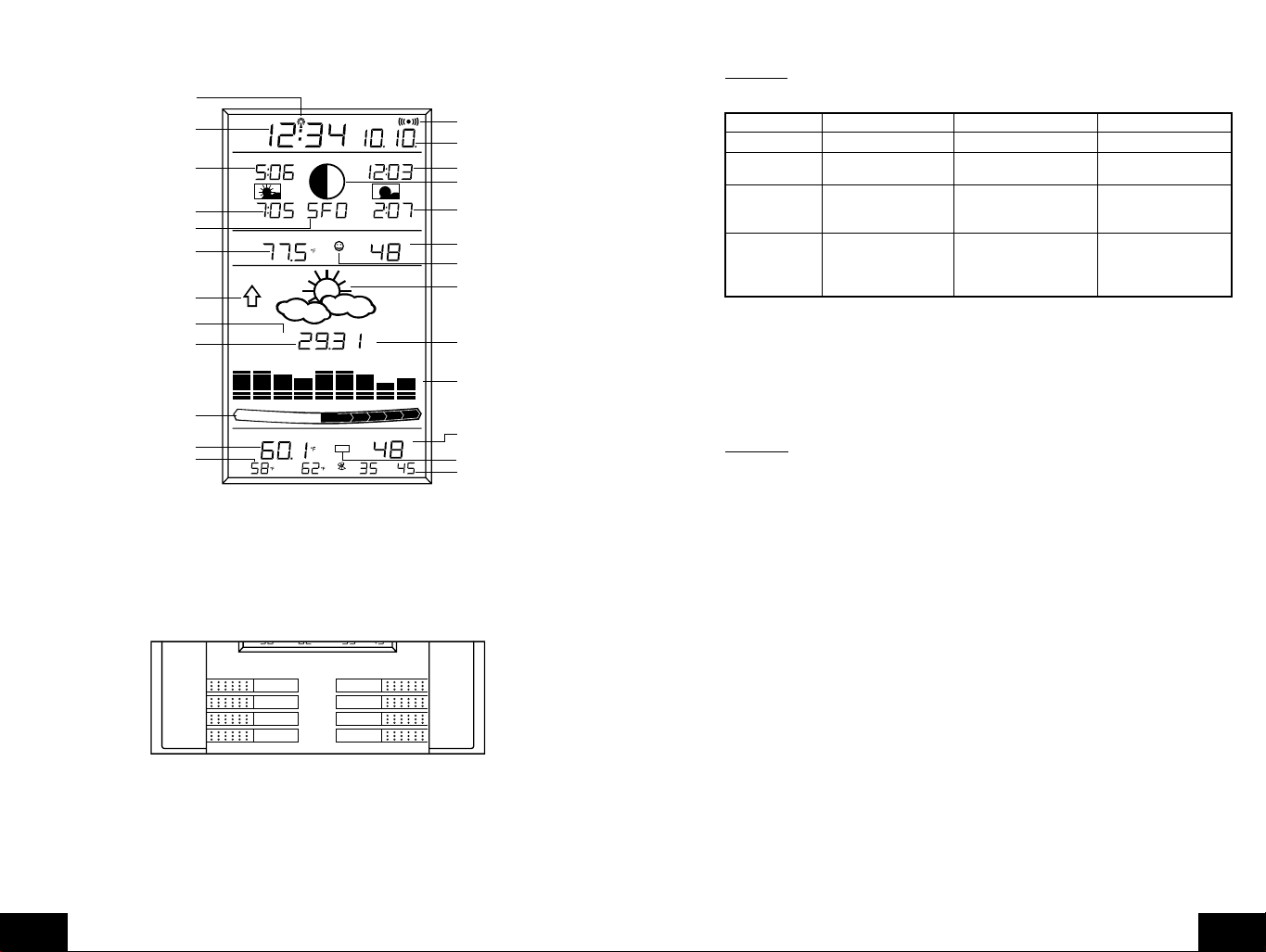
III. Explanation of LCD Information
A. The below picture highlights the LCD features
WWVB reception indicator
Radio-controlled time
Sunrise time for
selected location
Sunset time for
selected location
City code for city selected
(San Francisco, USA shown)
Indoor temperature
Air pressure tendency arrow
(increase displayed)
Relative or absolute air pressure
selection (relative shown)
Barometric air pressure
Pressure change over
last two hours (in hPa)
(+4 hPa shown)
Remote temperature
Remote temperature
minimum and maximum
OR alarm setting
TIME DATE
WWWB
SUNRISE MOON PHASE
PM PM
SUNSET
INDOOR TEMPERATURE
TENDENCY
PRESSURE
PRESSURE HISTORY
OUTDOOR TEMPERATURE
LO
MIN
LOCATION MOONSET
rel
HI
MAX
0
+0.2
2
MIN MAX
+0.5
MOONRISE +1
HUMIDITY
inHg
+1
HUMIDITY
%RH%
RH
-1h-3h-6h-9h-12h-18h-24h-30h
+2
%
+7
+5
+3
+1
0
-1
-3
-5
-7
01
+4
%
RH
RH
Alarm on indicator
Radio-controlled date
Moonset time for
selected location
Current moon phase
Moonset time for
selected location
Indoor humidity
Comfort icon
Forecast icon
Measuring unit for
air pressure, inHg
shown
Last 30 hour air
pressure graph
Remote humidity
Remote sensor number
(up to three total)
Remote humidity
minimum and maximum
B. There are many different modes the indoor weather station can be set to. The LCD shown
is the normal operating mode, and your actual data shown will be different based on your
local settings and conditions.
IV. Function Key Layout
A. The below picture shows the eight function keys used in programming and operation of
your indoor weather station.
MIN MAX MIN MAX
IN
OUT
ALARM
SET
MOON
SUN/
CH
+
–
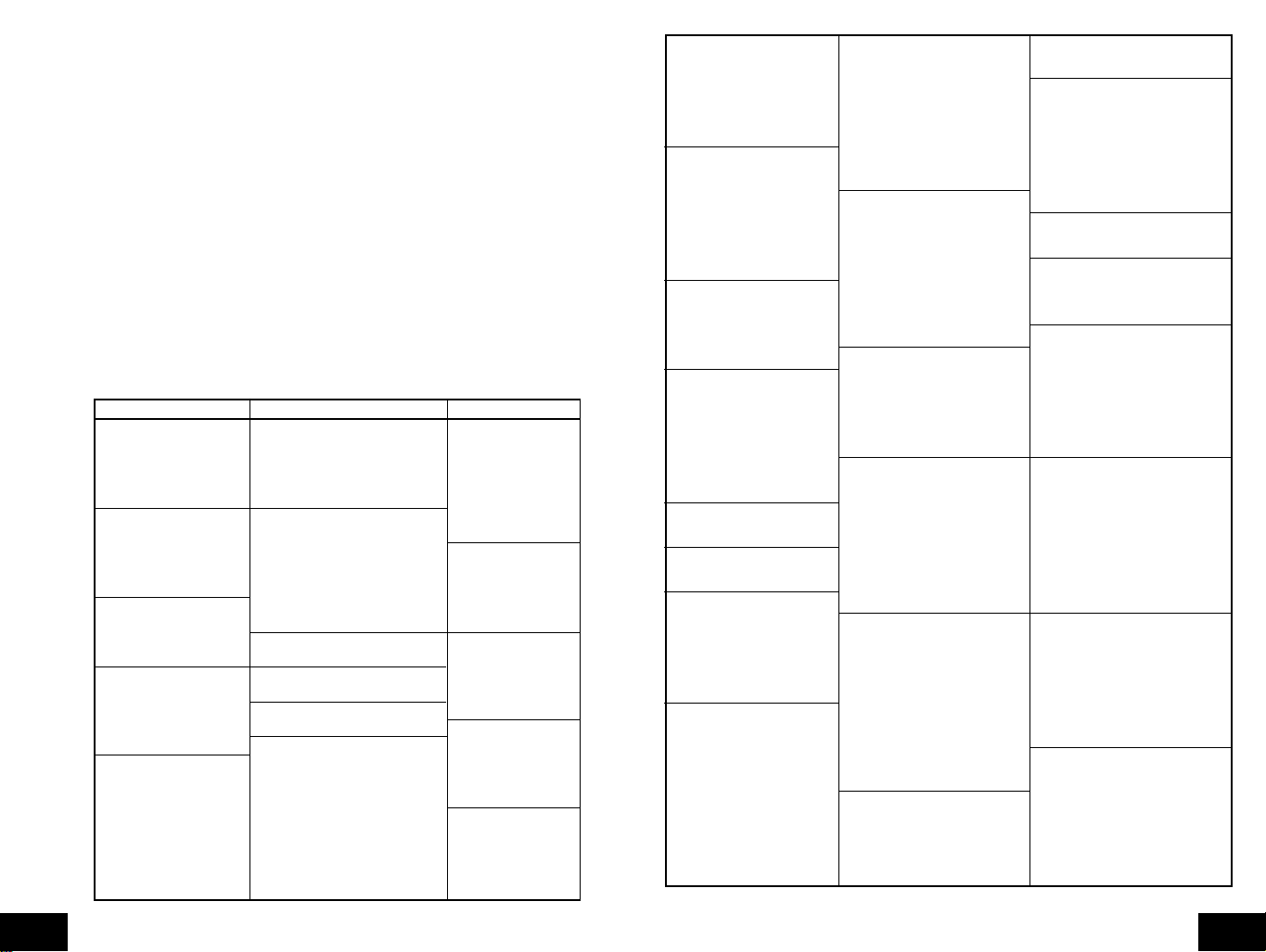
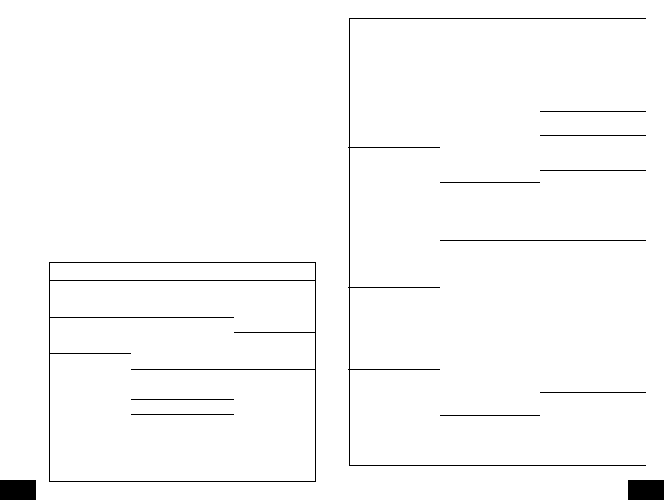
V. Program Mode
The program mode is laid out in a manner that allows you to program each function separately,
or you can follow the instructions entirely to program the indoor weather center. Complete
programming is usually done for the initial set-up, and will require you to skip step 1 and 2 of
each programming section. The prog ramming mode can be exited at any time b y either pressing
the "CH" button, or waiting for the 16-second time-out to take effect.
A. Overview of programming mode sequence
Note
: If the country setting is other than USA step 8 is city, step 9 is time zone, etc.
1. Hour 2. Minute 3. 12/24 hour 4. Year
5. Month 6. Date 7. Country 8. State
9. City 10. Time Zone 11. DST on/off 12. ˚F/˚C
13. inHg/hPa 14. Relative pressure 15. Forecast 16.Storm warning
setting sensitivity setting
17. Storm alarm 18. LCD contrast 19. LI on/off
on/off
B. Time, 12/24 Hour Mode and Date Setting
The WWVB signal will override any manual set time and date information. The time will be
based on the time zone selected.
1. Press and hold the "
SET
" button for 1 second.
2. The hour is now flashing.
3. Press and release the "+" or "-" button to select the current hour.
Note
: In 12h mode "PM" will appear to the left of the time during PM hours. If the time is
not within the PM hours nothing will be displayed. Be sure to set the time to the correct AM/
PM time to ensure automatic reception.
4. Press the "
SET
" button to advance to the minute
5. The minute is now flashing.
6. Press and release the "+"or "-" button to select the current minute.
7. Press and release the "
SET
" button to advance to the 12/24-hour setting.
8. "12" is now flashing.
9. Press and release the "+"or "-" button to select either 12 (am/pm) or 24 hour (military)
time format.
10. Press and release the "
SET
" button to advance to the year setting.
11. The year is now flashing.
12. Press and release the "+"or "-" button to select the current year.
13. Press and release the "
SET
" button to advance to the month setting.
14. The month is now flashing.
15. Press and release the "+"or "-" button to select the current month.
16. Press and release the "
SET
" button to advance to the date setting.
17. The date is now flashing.
18. Press and release the "+"or "-" button to select the current date.
19. Press and release the "
SET
" button to advance to the location setting (skip steps 1 and
2 in section B if continuing).
C. City Location Setting
The list of the cities available is listed after this section.
1. Press and hold the "
2. Press and release the "
SET
" button for 1 second.
SET
" button 6 times.
3. The country location will flash (USA default/factory setting).
4. Press and release the "+"or "-" button to select the country (USA=United States,
CAN=Canada, MEX=Mexico).
5. Press and release the "
SET
" button to advance to the state setting (USA only) or the
city location (Canada or Mexico).
GB
P.6
P.7
GB
Skip to step nine if Mexico or Canada is selected
6. The state is now flashing.
7. Press and release the "+"or "-" button to select the state.
8. Press and release the "
9. The city is now flashing.
10. Press and release the "+"or "-" button to select the city closest to your location
(abbreviated by airport code, if applicable).
11. Press and release the "
and 2 in section D if continuing).
SET
" button to advance to the city setting.
SET
" button to advance to the time zone setting (skip steps 1
Section C lists the available city codes. Section D continues with the setup programming.
D. City Location Listing
The following list of city locations is entered in the database. Due the limited memory, 245
cities are listed. Every attempt has been made to provide a location close to all parts of
North America. The choices were based first on state capitals , then nearby locations based
on population and difference of latitude and longitude. There are cases where your city
may be closer to a city in a nearby state rather than your state. We are unable to change
the database, but are open to suggestions for future locations. If you feel there is a city that
should be listed, please write to us (either mail or e-mail).
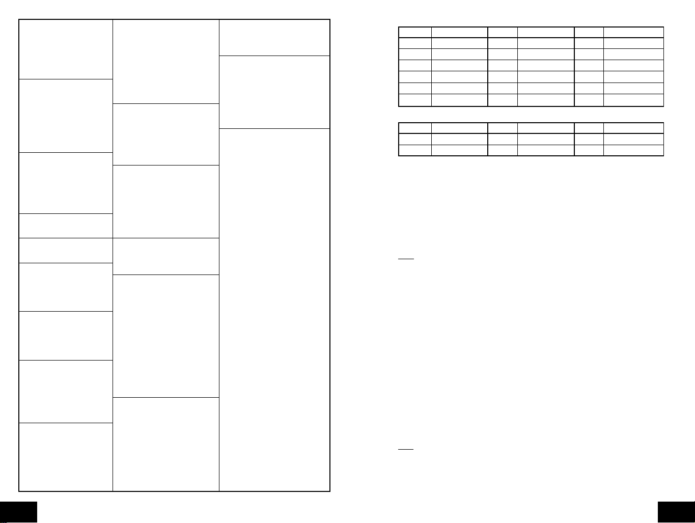
United States Cities, Listed by State
Code State/City Code State/City Code State/City
AK Alaska CA California (cont.) GA Georgia
ANC Anchorage SAC Sacramento ABY Albany
FAI Fairbanks SAN San Diego AGS Augusta
JNU Juneau SBD San Bernardino ATL Atlanta
OME Nome SFO San Francisco CSG Columbus
AL Alabama CO Colorado MAC Macon
BHM Birmingham DEN Denver SAV Savanna
GAD Gadsden DRO Durango HI Hawaii
MGM Montgomery FNL Ft. Collins HNL Honolulu
MOB Mobile GJT Grand Junction ITO Hilo
AR Arkansas ITR Burlington OGC Kahului
FSM Fort Smith PUB Pueblo WAI Waimea
LIT Little Rock CT Connecticut IA Iowa
TXK Texarkana HFD Hartford ALO Waterloo
AZ Arizona DC District of Columbia DSM Des Moines
FLG Flagstaff DCA Washington DVN Davenport
PHX Phoenix DE Delaware SUX Sioux City
TUS Tucson 0N5 Dover ID Idaho
YUM Yuma FL Florida BOI Boise
CA California EYW Key West GIB Gibbonsville
BFL Bakersfield JAX Jacksonville PIH Pocatello
BLH Blythe MIA Miami SZT Sand Point
EKA Eureka ORL Orlando IL Illinois
FAT Fresno PNS Pensacola CMI Champaign
FTB Ft. Bragg TLH Tallahassee ORD Chicago
LAX Los Angeles TPA T ampa SPI Springfield
ROD Redding
IN Indiana MN Minnesota ND North Dakota, cont.
EVV Evansville AEL Albert Lea GFK Grand Forks
HUF Terre Haute BJI Bemidji NE Nebraska
IND Indianapolis DLH Duluth GRI Grand Island
SBN South Bend GPO Grand Portage LNK Lincoln
KS Kansas INL International Falls OMA Omaha
DDC Dodge City STP St. Paul SNY Sidney
K32 Wichita MO Missouri VTN Valentine
KCK Kansas City JEF Jefferson City NH New Hampshire
OH1 Wakeeney MKC Kansas City CON Concord
TOP Topeka MPH Memphis NJ New Jersey
KY Kentucky POF Poplar Bluff EWR Newark
FFT Frankfort SGF Springfield TTN Trenton
LEX Lexington STL St. Louis NM New Mexico
LOU Louisville MS Mississippi ABQ Albuquerque
LA Louisiana GWO Greenwood MAG Magdalene
BTR Baton Rouge HUV Huntsville ROW Roswell
CWF Lake Charles JAN Jackson RTN Raton
IER Natchitoches TUP Tupelo SAF Santa Fe
NEW New Orleans MT Montana NV Nevada
SHV Shreveport BIL Billings AIN Austin
MA Massachusetts FTP Ft. Peck CXP Carson City
BOS Boston GFT Great Falls ELY Ely
MD Maryland HLN Helena LAS Las V egas
BWI Baltimore SDY Sidney LWL Wells
ME Maine WTF Whitefish RNO Reno
AUG Augusta NC North Carolina NY New York
BGR Bangor AVL Asheville ALB Albany
CAR Caribou CLT Charlotte BUF Buffalo
PWM Portland FAY Fayetteville JFK New Y ork City
MI Michigan ILM Wilmington LKP Lake Placid
AZO Kalamazoo INT Winston-Salem SYR Syracuse
DET Detroit MCZ Williamston OH Ohio
FNT Flint RDU Raleigh CLE Cleveland
LAN Lansing ND North Dakota CMH Columbus
PZQ Rogers City BIS Bismarck ISZ Cincinnati
SAW Marquette BWB Bowbells TOL Toledo
TVC Traverse City FAR Fargo YNG Youngstown
GB
P.8
P.9
GB
OK Oklahoma TX Texas (cont.) WV West Virginia
17K Boise City DFW Dallas/Ft. Worth CRW Charleston
LAW Lawton ELP El Paso HLG Wheeling
OKC Oklahoma City HOU Houston WY Wyoming
TUL Tulsa LRD Laredo BYG Buffalo
OR Oregon ODO Odessa CPR Casper
BNO Burns SAT San Antonio CYS Cheyenne
EUG Eugene UT Utah LAA Little America
MFR Medford SAL Saline WYE West Y ellowstone
PDX Portland SGU St. George
SLE Salem SLC Salt Lake City
PA Pennsylvania TSN Thompson
CXY Harrisburg VA Virginia
PHL Philadelphia DON Vienna
PIT Pittsburgh LYH Lynchburg
SCR Scranton ORF Norfolk
PR Puerto Rico RIC Richmond
SJU San Juan ROA Roanoke
RI Rhode Island VT Vermont
PVD Providence BTV Burlington
SC South Carolina MPR Montpelier
CHS Charleston WA Washington
CUB Columbia ABE Aberdeen
GMU Greenville ALW Walla W alla
SD South Dakota KTF Kettle Falls
FSD Sioux Falls MVN Mt. Vernon
PIR Pierre OLM Olympia
RAP Rapid City SEA Seattle
TN Tennessee SFF Spokane
BNA Nashville TON Tonasket
CHA Chattanooga YKM Yakima
DKX Knoxville WI Wisconsin
MEM Memphis AUW Wausau
TX Texas GRB Green Bay
ABI Abilene LSE La Crosse
AMA Amarillo MSN Madison
AUS Austin MWC Milwaukee
BRO Brownsville SSQ Spooner
Canada City Listing
Code City Code City Code City
EDM Edmonton YEL Yellowknif e CHT Charlotte Town
ALB Calgary OTT Ottawa MON Montreal
VAN Vancouver SUD Sudbury QUE Quebec
WIN Winnipeg THU Thunder Bay REG Regina
FRE Fredericton TOR Toronto WHI Whitehorse
HAL Halifax
Mexico City Listings
Code City Code City Code City
CHH Chihuahua MEX Mexico City HER Hermosillo
DUR Durango GUA Guadalupe
E. Time Zone and Daylight Saving Time Settings
1. Press and hold the "
2. Press and release the "
3. The time zone will now flash based on the city selected.
4. Press and release the "+"or "-" button to adjust to the correct time zone.
5. Press and release the "
6. "dst ON" will now flash.
7. Press and release the "+" or "-" button to select DST 1 (recognizes Daylight Saving
Time change) or DST 0 (does not change with Daylight Saving Time).
Note
: Some locations (Arizona and parts of Indiana) do not follow Daylight Saving Time.
8. Press and release the "
settings (skip steps 1 and 2 in section E if continuing).
F. Weather measurement units (˚F/˚C, inHg/hPa)
1. Press and hold the "
2. Press and release the "
3. The selected temperature units will now flash (˚F default/factory setting).
4. Press and release the "+"or "-" button to select ˚F (Fahrenheit) or ˚C (Celsius).
5. Press and release the "
setting.
6. The selected air pressure units will now flash (inHg default/factory setting).
7. Press and release the "+"or "-" button to select inHg (inches of Mercury) or hPa
(hectopascal or millibars).
8. Press and release the "
setting.
9. The air pressure reading will now flash (29.91 inHg, 1012.8 hPa as default).
10. Press and release the "+"or "-" button to adjust to the correct relative air pressure
based on local reports.
11. Press and release the "
Note
: Barometric air pressure is usually reported as "relative air pressure". This reading is
based on the combination of absolute air pressure and altitude. In general, an increase in
altitude will result in a decrease in air pressure. Relative air pressure will make readings in
nearby locations relative to each other to allow for proper forecasting. The absolute air
pressure reading in the Weather Center cannot be calibrated, only the relativ e air pressure .
SET
" button for 1 second.
SET
" button 9 times.
SET
" button to advance to the Daylight Saving Time setting.
SET
" button to advance to the weather measurement units
SET
" button for 1 second.
SET
" button 11 times.
SET
" button to advance to the barometric air pressure units
SET
" button to advance to the barometric air pressure calibration
SET
" button to advance to the forecast sensitivity setting.
GB
P.10
P.1 1
GB
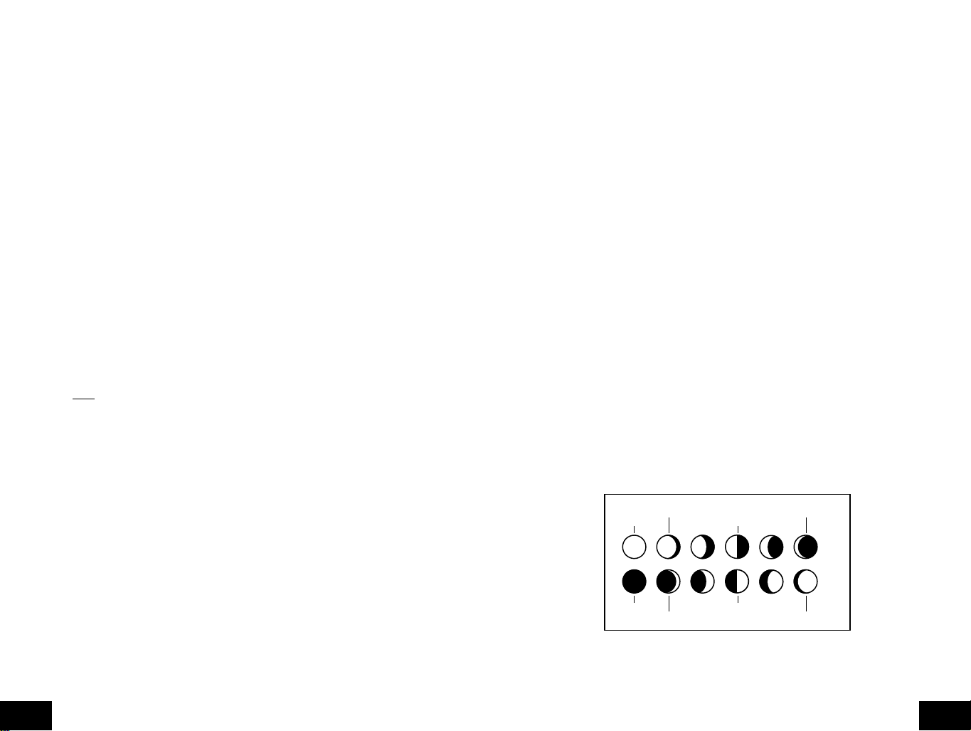
New Moon
Waxing Crescent Waxing Gibbous
First Ouarter
Full Moon
Waning Gibbous Waning Crescent
Last Ouarter
12. The selected forecast sensitivity setting will now flash (0.09 inHg default).
13. Press and release the "+"or "-" button to select 0.06, 0.09, or 0.12 inHg (if hPa is
selected, the choices will be 2, 3, or 4). A lower setting will result in a quic k er change in
the forecast icon. In other words, if the setting is 0.06 inHg, the forecast icon will change
if the air pressure changes by at least 0.06 inHg within a six-hour period. This is useful,
as certain areas will have a change of air pressure but no change in weather.
14. Press and release the "
SET
" button to advance to the storm warning setting.
15. The selected storm warning level will now flash (0.15 inHg, 5 hPa default).
16. Press and release the "+"or "-" button to select the storm warning setting. This can be
set to 0.09, 0.12, 0.15, 0.18, 0.21, 0.24, or 0.27 inHg (from 3 to 9 hPa). This setting will
determine how much of a drop in air pressure over six hours will sound the storm
warning alarm.
17. Press and release the "
SET
" button to advance to the storm warning alarm on/off
setting.
18. The storm warning on or off setting will now flash (AOFF default/factory setting).
19. Press and release the "+"or "-" button to select whether or not the storm warning alarm
is activated.
20. Press and release the "
SET
" button to advance to the LCD setting (skip steps 1 and 2
in section F if continuing).
f. Press and release the "+" or "-" key to select the state (see listing on pages 8 to 11).
g. Press and release the "
SET
" key to advance to the city selection.
h. The city is now flashing.
i. Press and release the "+" or "-" key to select the city.
j. Press and release the "
SET
" key to advance to the date setting.
If the sunrise/set moonrise/set times are desired for the current date, the "SUN/MOON"
key may be pressed to calculate. Skip to step t for further explanation.
k. The year is now flashing (the current year).
l. Press and release the "+" or "-" key to select the year desired.
m. Press and release the "
SET
" key to advance to the month setting.
n. The month is now flashing (the current month).
o. Press and release the "+" or "-" key to select the month desired.
p. Press and release the "
SET
" key to advance to the date setting.
q. The date is now flashing (the current date).
r. Press and release the "+" or "-" key to select the date desired.
s. Press and release the "
SUN/MOON
" key to calculate the new city location at the date
selected.
G. LCD Contrast
1. Press and hold the "
2. Press and release the "
SET
" button for 1 second.
SET
" button 17 times.
3. The LCD contrast setting will now flash (4 is the default/factory setting).
4. Press and release the "+"or "-" button to select the contrast level desired (from 1 to 8).
5. Press and release the "
SET
" button to advance to the LI setting.
6. The LI setting will now flash (ON is the default/factory setting).
7. Press and release the "+"or "-" button to select ON or OFF.
8. Press and release the "
Note
: The LI setting does not affect the function of the indoor weather station and is
SET
" button to exit the programming mode.
present only for future use.
FEATURES AND OPERATIONS
A. Sunrise/set and Moonrise/set Calculation
The indoor weather station will calculate the sunrise/set moonrise/set each day based on the
location entered through the programming mode. To view another location and/or date without
affecting the programmed city location and date, f ollow section A.2 in F eatures and Operations .
1. Daylight Hours and Minutes Calculation
Press and release the "SUN/MOON" button. In place of the sunrise/sunset time will be the
number of daylight hours and minutes. Press the "SUN/MOON" button to view the sunrise/
sunset time again.
2. View Different Location/Time for Sunrise/set and Moonrise/set
If no buttons are pressed in 30 seconds during this selection the indoor weather station will
revert to the normal mode. Alternatively, you may press the "CH" key to revert to the
GB
normal mode.
a. Press and hold the "
SUN/MOON
" key for at least two seconds.
b. The selected country will now flash.
c. Press and release the "+" or "-" key to select the desired country.
d. Press and release the "
SET
" key to advance to the state selection (or city if Canada or
Mexico is selected skip to step h.).
e. The state is now flashing.
P.12
You may instead press the "SET" k ey to select a different location, starting at step b above.
t. Once the "SUN/MOON" key is pressed, the sunrise/set and moonrise/set times will
flash as dashes while the indoor weather station calculates the times (the moon phase
is calculated, also). Once the times are displayed, the indoor weather station will remain
in this mode for 30 seconds or until the "
CH
" key is pressed. The year, month, or date
will also be flashing. At this time it is possible to start at step b. to select another date or
location.
u. Once this mode is exited either through timeout after 30 seconds or by pressing the
"
CH
" button, the indoor weather station will revert to the normal mode with the location
and date set through the programming mode. The indoor weather station will default to
the last city selected when this mode is entered again.
B. Moon Phase
1. There are 12 moon phases shown on the indoor weather station; the black portion signifies
the portion of the moon visible in the sky. Thus, when the moon icon is all black, it is a full
moon. The indoor weather station is programmed with all moon phases from the year
2000 until 2099.
2. The moon phase for any date may be found by selecting a different date through the sun
rise/set moon rise/set programming section (section A in Features and Operations).
P.13
GB

C. Minimum and Maximum Temperature and Humidity
1. Indoor Minimum and Maximum Temperature and Humidity
The indoor weather station automatically stores the minimum and maximum indoor
temperature and humidity. The minimum and maximum values are updated automatically
when a new minimum or maximum is recorded, or until manually reset.
a. From the normal display mode, press and release the "
minimum temperature and humidity ("MIN" will be displayed near the indoor temperature
and humidity).
b. Press and release the "
humidity.
c. Press and release the "
minimum/maximum values will occur if no keys are pressed for fifteen seconds).
IN
" key again to view the indoor maximum temperature and
IN
" key again to return to the normal mode (timeout of viewing
IN
" key once to view the indoor
2. Viewing and Operating with Multiple Remote Sensors
a. To vie w the temperature of a diff erent remote sensor press and release the "
button. A shift from one "bo xed" n umber to the next should be observed in the OUTDOOR
LCD.
b. The minimum and maximum temperature of the additional remote sensor will be
displayed below the current temperature of the remote sensor in the OUTDOOR LCD.
c. To reset the minimum and maxim um temperature readings press and hold the "
button for 5 seconds and the records for all the remote sensor will be reset.
Each remote sensor will have its own minimum and maximum values stored, as well as its
own alarm settings for temperature. Resetting the outdoor minimum and maximum values
will reset all remote sensors' recordings.
E. Remote Temperature Alarm
CHANNEL
RESET
"
"
Note
: To reset the indoor minimum and maximum temperature and humidity, press and
hold the "IN" key for at least two seconds.
2. Outdoor Minimum and Maximum Temperature and Humidity
The indoor weather station automatically stores the minimum and maximum outdoor
temperature and humidity. The minimum and maximum values are updated automatically
when a new minimum or maximum is recorded, or until manually reset.
a. The outdoor (remote) minimum and maximum temperature values are displayed below
the outdoor temperature display.
b. These values are rounded down for minimum and rounded up for maximum.
Note : The temperature alarm mode shares the same display. When the alarm values are
displayed, "ALARM" will be displayed above the remote temperature. To switch back and
forth between views, press the "OUT" key.
c. To reset the outdoor minimum and maximum temperatures press and hold the "CH"
key for at least one second.
D. Multiple Remote Temperature Sensors
The WS-8025SU is able to receive signals from 3 diff erent remote sensors . These extra remote
sensors can be purchased through the same dealer as this unit. A TX4U will monitor the
temperature and humidity , a TX3U will monitor temperature and displa y the temperature on its
LCD and the TX3UP will monitor the temperature via a probe for measuring soil or water
temperatures.
Note
: When setting up multiple units it is important to insert batteries first into all the remote
sensors, and in numeric sequence. Second install batteries into the indoor weather station.
Transmission problems will arise if this is not done correctly and if the total time for set-up
exceeds 6 minutes
1. Set Up of Multiple Units
a. It is necessary to remove the batteries from all units currently in operation.
b. Remove the battery covers to all remote sensors.
c. Place all remote sensors in a numeric sequential order.
d. In sequential order, install batteries following the same battery installation procedures
seen in Detailed Set-Up Guide section of this manual.
e. Install batteries into the indoor weather station.
f. Follow the Detailed Set-Up Guide for programming and operating instructions.
1. Activating the alarm
From the normal mode, press and release the "
alarm and minimum/maximum values. "
temperature display; this will also activate the temperature alarm.
2. Setting the temperature alarm
a. Press and hold the "
b. The low temperature will be flashing (32˚F default/factory setting).
c. Press and release the "+" or "-" key to adjust the temperature from -22˚F to +157˚F
("- -" if outside this range). Any value attained below this will sound the alarm.
d. Press and release the "
e. The high temperature setting is now flashing (86˚F default/factory setting).
f. Press and release the "+" or "-" key to adjust the temperature from -22˚F to +157˚F
("- -" if outside this range). Any value attained above this value will sound the alarm.
g. Press and release the "
will timeout after fifteen seconds and return to the normal mode automatically).
3. Canceling the Temperature Alarm While Sounding
a. While the alarm is sounding, press any key to mute the alarm. The temperature will
flash as long as the value is above the set value.
b. The alarm will reactivate automatically once the value has fallen below the set value,
or if a new value is entered.
F. Comfort Indicator for Indoor Temperature and Humidity
1. The comfort level indicator appears inbetween the indoor tempearture and humidity.
2. The indicator will display a "happy-face" when the temperature is between 68˚F and 79˚F
(20˚C and 25.9˚C), and the humidity is between 45% and 64%.
3. A "sad-face" will be displayed when the temperature and humidity are outside the mentioned
ranges.
4. If the humidity is below 45% the word "DRY" will appear to the right of the "sad-face" icon.
5. If the humidity is above 54% the word "WET" will appear to the right of the "sad-face" icon.
G. Weather Forecast Icon and Pressure Trend Indicators
The weather forecasting feature is estimated to be 75% accurate, and is based solely upon
the change of air pressure over time. The WS-8025SU a verages past air-pressure readings to
provide an accurate forecast-creating a necessity to disregard all weather forecasting for 1224 hours after the unit has been set-up, reset, or moved from one altitude to another (i.e. from
one floor of a building to another floor). In areas where the weather is not affected by the
change of air pressure, this feature will be less accurate.
OUT
" key for two seconds.
SET
" key to advance to the high temperature alarm.
SET
" key to return to the normal display mode (or the display
OUT
ALARM
" key to toggle between the temperature
" will be displayed above the remote
GB
P.14
P.15
GB
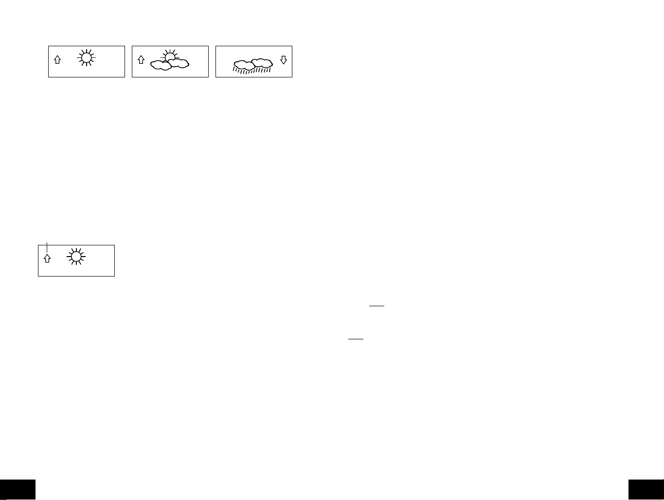
1. Weather Icons
a. There are 3 possible weather icons that will be displayed at various times in the
center of the indoor weather station.
i
Sunny
- indicates that the weather is expected to improve (not that the weather
will be sunny).
ii
Sun with Clouds
weather will be sunny with clouds).
iii
Clouds with Rain
the weather will be rainy).
b. The weather icons change when the unit detects a change in air pressure.
c. The icons change in order, from "sunny" to "sun with clouds" to "clouds with
rain" or the reverse.
d. It will not change from "sunny" directly to "clouds with rain", although it is possible
for the change to occur quickly.
e. If the symbols do not change, the weather has not changed (or the change has
been slow and gradual).
f. The sensitivity of the change in foreacst icon is set by the user in section F of
the Detailed Set Up Guide.
H. Weather Tendency Arrows
Pressure trend arrow
1. Along with the forecast icon there is a pressure tendency arrow.
2. There is one that points up (on the left side of the LCD) and one that points down
(on the right side of the LCD).
3. These arrows reflect current changes in the air pressure.
4. An arrow pointing up indicates that the air pressure is increasing and the weather is
expected to improve or remain good.
5. An arrow pointing down indicates that the air pressure is decreasing and the weather
is expected to become worse or remain poor.
6. No arrow means the pressure is stable.
7. A storm can be expected if there is a drop of 4 hPa or more in less than 6 hours.
The clouds with rain icon will be displayed and the tendency arrow that points down
will be flashing-indicating the storm warning feature has been activated. The flashing
will stop when the air pressure stabilizes or begins to rise.
I. Storm Warning Alarm
1. An alarm can be set to warn of a drop in air pressure.
2. Please follow the programming instructions in section F of the Detailed Set Up
Guide to activate this alarm
3. When the air pressure drops by the level set, an alarm will sound (if the alarm is
activted).
4. To cancel the alarm while sounding press any key.
- indicates that the weather is expected to be fair (not that the
- indicates that the weather is expected to get worse (not that
J. Air Pressure Tendency for Past Two Hours
The bar below the air pressure history chart displays the air pressure change over the past
two hours (values based on hPa change, 1 hPa equals 0.03 inHg).
K. Barometric Air Pressure Reading
1. The actual barometric air pressure is displayed directly under the weather forecast icon
2. The relative air pressure is calibrated by the user through the programming mode.
3. Please Follow the programming instructions in section F of the Detailed Set Up Guide to
set this feature.
4. To toggle between absolute and relative air pressure, press the "-" key.
L. Air Pressure History Bar Chart
1. The bar graph shows in hPa (Hekto Pascal) the recorded air pressure over the past 30hours.
2. The horizontal axis shows the hours at increments of -30 hours, -24 hours, -18 hours, -12
hours, -6 hours, -3 hours, -1 hours, and 0 hours (current).
3. The vertical axis is set by hPa: the "0" on this axis represents the current hPa, and + or
-1,3,5, or 7 shows (in hPa) how high or low the past air pressure was as compared to the
current one.
4. The "0" on the vertical axis indicates the current air pressure value.
5. The "0h" on the horizontal axis indicates the current hour, thus the current air pressure
also.
6. Each bar on the bar graph represents a value of 0.03 hPa, and each bar also has a
corresponding value on the verticle axis.
7. Air pressure trends can be determined by simply glancing at the bar graph.
a. If the bars are rising (higher on the right than the left) then the air pressure has a rising
trend, and the weather should improve.
b. If the bars are dropping (lower on the right than the left) then the air pressure has a
falling trend, and the weather should worsen.
8. Multiply the two values to find past air pressure (note the + or - sign of values on the
verticle axis); i.e. 0.03 hPa x 3 = 0.09 hPa, now add this value to the air pressure (in LCD
4) to evaluate what past air pressures have been.
9. The bar chart will constantly scroll to avoid burnout of the LCD.
Note
: This feature cannot be turned off.
MOUNTING
Note
: Before permanently mounting, ensure that the indoor weather station is able to receive signals
from the transmitters and WWVB signal at the desired location. To achieve a true temperature reading,
avoid mounting the remote thermo/hygro sensor (or any sensor) where direct sunlight can reach the
remote sensor. We recommend that you mount the remote sensor on a North-facing wall or under an
eve. The sending range of the remote thermo/h ygro sensor is 200 feet(60m) however obstacles such
as walls, concrete, and large metal objects can reduce the range. Place all units in their desired
location, and wait approximately 15 minutes before permanently mounting to ensure that there is
proper reception. If the indoor weather station loses the signal from the remote sensor, it will display
the last temperature reading for 15 minutes. After 15 minutes of not receiving any signals, the remote
temperature will display "- -.-".
A. Mounting the Remote Thermo/hygro Sensor
The remote thermo/hygro sensor can be mounted with the use of screws or by using the
adhesive tape.
GB
P.16
P.17
GB
1. Mounting with screws
a. Remove the mounting bracket/receptor from the packaging.
b. Place the mounting bracket over the desired mounting surface.
c. Through the 2 screw holes of the bracket, mark the mounting surface with a pencil.
d. Where marked, start the screw holes using the provided screws.
e. Remove screws from the mounting surface.
f. Align the mounting bracket with the started screw holes.
g. Screw mounting bracket onto the mounting surface. The screws should be flush with
the bracket.
h. Fit the mounting post (on the back of the transmitter) into the receptor of the mounting
bracket.
REMOTE
THERMO-SENSOR
433 MHz
REMOTE
THERMO-SENSOR
433 MHz
2. Mounting with Adhesive Tape
a. With a nonabrasive solution, clean and dry the back of the mounting bracket and the
mounting surface to ensure a secure hold. The mounting surface should be smooth
and flat.
b. Remove the protective strip from one side of the tape.
c. Press firmly onto the designated area on the back of the mounting bracket.
d. Remove the protective strip from the other side of the tape, and situate the mounting
bracket.
e. Firmly press the mounting bracket onto the mounting surface.
f. Fit the mounting post into the receptor of the mounting bracket.
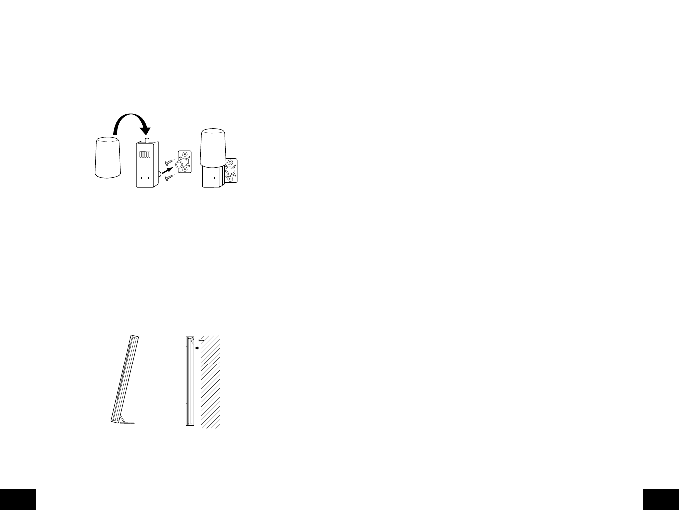
B. Mounting the WS-8025SU Weather Center
The indoor weather station can be mounted in two ways; free standing or hanging on a wall.
To have the indoor weather station free standing, simply unf old the stands on the bac k and set
on a stable flat surface.
Maintenance and Care Instructions
A. Extreme temperatures, vibration, and shock should be avoided to prevent damage to the units.
B. Clean displays and units with a soft, damp cloth. Do not use solvents or scouring agents; they
may mark the displays and casings.
C. Do not submerge in water.
D. Immediately remove all low powered batteries to avoid leakage and damage.
E. Opening the casings invalidates the warranty. Do not try to repair the unit. Contact La Crosse
Technology for repairs.
TROUBLESHOOTING
Problem : The LCD is faint.
Solution : 1) Set the LCD contrast to a higher level.
2) Replace batteries.
Problem : No outdoor temperature/humidity is displayed.
Solution : 1) Remove all batteries, reinsert into the remote thermo/hygro sensor first, then into the
indoor weather station.
2) Place remote thermo/hygro sensor closer to the indoor weather station.
3) Be sure all batteries are fresh.
4) No other interfering sources are being used (such as computer monitors, TV sets,
headphones, or speakers) in the vicinity. The signal tra vels in a straight line , an electrical
source near that "line" may cause interference.
Problem : Temperature, humidity, or air pressure is incorrect.
Solution : 1) Check/Replace batteries.
2) If multiple remote sensors are in use, check location with corresponding "boxed
numbers."
3) Move away from sources of heat/cold.
4) Adjust relative air pressure to a value from a reliable source (TV radio, etc.).
5) The indoor weather station and remote sensors are calibrated at the factory. If there is
a consistent problem, please call La Crosse Technology.
Problem : "- -" in humidity display.
Solution : 1) Humidity is below 1% or above 99%.
2) TX3U or TX3UP is used for remote temperature.
Problem : WWVB time and date will not set or update
Solution : 1) Wait until overnight for signal to be received
2) Move indoor weather station away from sources of electricity
3) Place indoor weather station in window facing Colorado
4) The first reception is most difficult, as the indoor weather station needs five continual
minutes of clear signal reception. After the initial time/date set, the indoor weather
station only requires one full minute of clear reception each night.
To wall mount the indoor weather station;
1. Ensure that the integrated stands are folded in.
2. Fix a screw (not included) into the desired wall, leaving approximately 3/16 of an inch
(5mm) extended from the wall.
3. Place the indoor weather station onto the screw using the hanging hole on the backside.
Gently pull the indoor weather station down to lock the screw into place.
P.18
GB
SPECIFICATIONS
Radio-controlled Time Signal WWVB, 60 kHz from Ft. Collins, CO
Indoor weather station recommended
operating temperature 32˚F to 122˚F (0˚C to 50˚C)
LCD contrast 8 levels (1-8)
Sunrise/set, Moonrise/set, and moon phase
dates available January 1, 2000 through December 31, 2099
P.19
GB

Temperature measuring range
Indoor 14˚F to 140˚F with 0.2˚F resolution
Outdoor -21.8˚F to 157.8˚F with 0.2˚F resolution
Relative humidity range
Indoor/Outdoor 1% to 99% with 1% resolution, indoor weather
Air pressure
Absolute hPa/inHg 700 hPa to 1099 hPa
Relative hPa (adjustable) 960 hPa to 1040 hPa
Relative inHg (adjustable) 28.60 inHg to 30.45 inHg
Sensitivity setting hPa 1 hPa to 4 hPa
Air pressure history For the past 30 hours (0, -1, -2, -3, -6, -12, -18, -24
Data checking intervals
Indoor temperature Every 15 second
Indoor humidity Every 20 seconds
Outdoor temperature Every 5 minutes
Outdoor humidity Every 5 minutes
Transmitter reading update (within sensor)
Outdoor temperature Every 1 minute
Outdoor humidity Every 1 minute
Transmission frequency 433.92 MHz
Transmission range 200 feet (60meter) open space
Power supply
Weather Center: 3 x AA, IEC LR6, 1.5V batteries.
Thermo Hygro Transmitter: 2 x AA, IEC LR6, 1.5V batteries.
Dimensions (L x W x H)
Indoor weather station 7.75 x10.00 x 1.00 inches
Remote thermo/hygro sensor 1.56 x 0.78 x 4.29 inches
(-9.9˚C to 59.9˚C with 0.1˚C resolution)
"OFL" displayed if outside this range)
(-29.9˚C to 69.9˚C with 0.1˚C resolution)
"OFL" displayed if outside this range
station displays "--.-" if outside this range
(20.67 inHg to 32.46 inHg)
and -30 hours)
(196 x 254 x 25mm)
(40 x 20 x 110 mm)

WARRANTY INFORMATION
La Crosse Technology, Ltd provides a 1-year limited warranty on this
product against manufacturing defects in materials and workmanship.
This limited warranty begins on the original date of purchase, is valid
only on products purchased and used in North America and only to
the original purchaser of this product. To receive warranty service,
the purchaser must contact La Crosse Technology, Ltd for problem
determination and service procedures. Warranty service can only be
performed by a La Crosse Technology, Ltd authorized service center.
The original dated bill of sale must be presented upon request as
proof of purchase to La Crosse Technology, Ltd or La Crosse
Technology, Ltd’s authorized service center.
La Crosse Technology, Ltd will repair or replace this product, at our
option and at no charge as stipulated herein, with new or
reconditioned parts or products if found to be defective during the
limited warranty period specified above. All replaced parts and
products become the property of La Crosse Technology, Ltd and
must be returned to La Crosse Technology, Ltd. Replacement parts
and products assume the remaining original warranty, or ninety (90)
days, whichever is longer. La Crosse Technology, Ltd will pay all
expenses for labor and materials for all repairs covered by this
warranty. If necessary repairs are not covered by this warranty, or if
a product is examined which is not in need or repair, you will be
charged for the repairs or examination. The owner must pay any
shipping charges incurred in getting your La Crosse Technology, Ltd
product to a La Crosse Technology, Ltd authorized service center.
La Crosse Technology, Ltd will pay ground return shipping charges to
the owner of the product to a USA address only.
Your La Crosse Technology, Ltd warranty covers all defects in
material and workmanship with the following specified exceptions: (1)
damage caused by accident, unreasonable use or neglect (including
the lack of reasonable and necessary maintenance); (2) damage
occurring during shipment (claims must be presented to the carrier);
(3) damage to, or deterioration of, any accessory or decorative
surface; (4) damage resulting from failure to follow instructions
contained in your owner’s manual; (5) damage resulting from the
performance of repairs or alterations by someone other than an
authorized La Crosse Technology, Ltd authorized service center; (6)
units used for other than home use (7) applications and uses that this
product was not intended or (8) the products inability to receive a
signal due to any source of interference.. This warranty covers only
actual defects within the product itself, and does not cover the cost of
installation or removal from a fixed installation, normal set-up or
1

adjustments, claims based on misrepresentation by the seller or
performance variations resulting from installation-related
circumstances.
LA CROSSE TECHNOLOGY, LTD WILL NOT ASSUME LIABILITY
FOR INCIDENTAL, CONSEQUENTIAL, PUNITIVE, OR OTHER
SIMILAR DAMAGES ASSOCIATED WITH THE OPERATION OR
MALFUNCTION OF THIS PRODUCT. THIS PRODUCT IS NOT TO
BE USED FOR MEDICAL PURPOSES OR FOR PUBLIC
INFORMATION. THIS PRODUCT IS NOT A TOY. KEEP OUT OF
CHILDREN’S REACH.
This warranty gives you specific legal rights. You may also have
other rights specific to your State. Some States do no allow the
exclusion of consequential or incidental damages therefore the above
exclusion of limitation may not apply to you.
For warranty work, technical support, or information contact:
La Crosse Technology, Ltd
2809 Losey Blvd S.
La Crosse, WI 54601
Phone: 608.782.1610
Fax: 608.796.1020
e-mail:
support@lacrossetechnology.com
(warranty work)
sales@lacrossetechnology.com
(information on other products)
web:
www.lacrossetechnology.com
2

FCC DISCLAIMER
This device complies with part 15 of the FCC rules. Operation is
subject to the following two conditions:
(1) This device may not cause harmful interference.
(2) This device must accept any interference received,
including interference that may cause undesired
All rights reserved. This handbook must not be reproduced in any
form, even in excerpts, or duplicated or processed using electronic,
mechanical or chemical procedures without written permission of the
publisher.
This handbook may contain mistakes and printing errors. The
information in this handbook is regularly checked and corrections
made in the next issue. We accept no liability for technical mistakes
or printing errors, or their consequences.
All trademarks and patents are acknowledged.
operation.
La Crosse Technology
Made in China
3
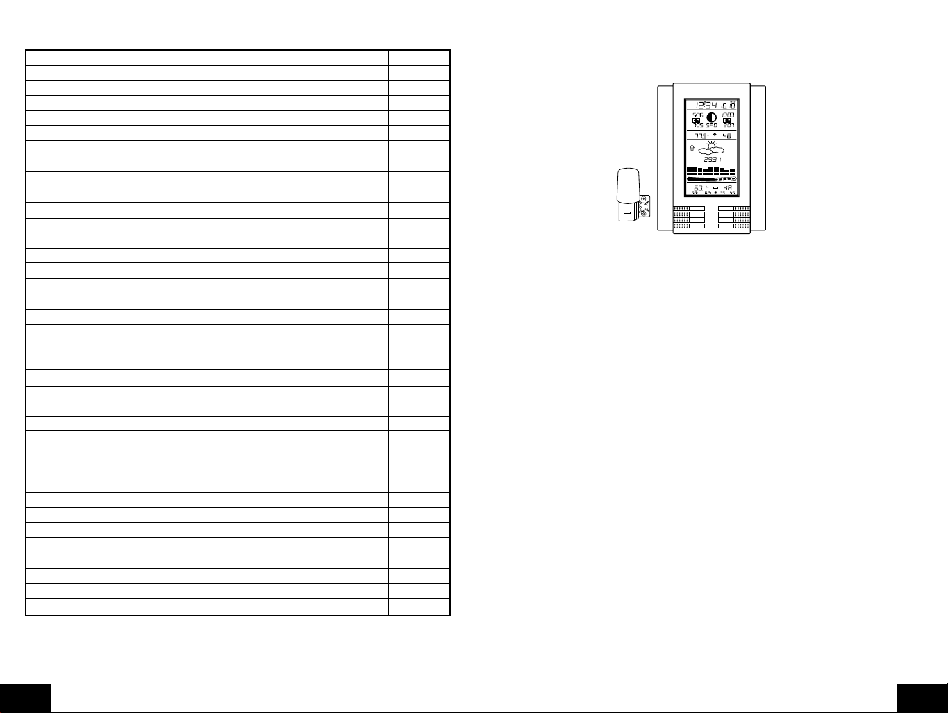
TABLE DES MATIERES
CONTENU
1. WS-8025SU-station météo intérieure
Sommaire Page
Contenu/ Equipement supplémentaire 23
2. TX4U-capteur thermo/hygro radio-piloté (température/hygrométrie)
3. Mode d'emploi et certificat de garantie
A propos de la station WWVB 23
Guide d'installation rapide 23
Guide d'installation détaillé 24
Installation des piles 24
Séquence de démarrage 25
Explication des informations LCD 26
Disposition des touches de fonction 26
Mode de programmation
Heure, mode de format 12/24 heures et réglage de la date 27
26
REMOTE
THERMO-SENSOR
433 MHz
Réglage de l'emplacement de la ville 27
Codes des villes des Etats-Unis 28
Codes des villes du Canada 31
Codes des villes du Mexique 31
Réglage de fuseau horaire 31
Réglage d'heure d'été (DST) 31
Unités de mesure météo31
Contraste LCD 32
Caractéristiques et fonctionnement 32
Calcul du lever/coucher du soleil et du lever/coucher de la lune 32
Phase de la lune 34
Température mini/max/hygrométrie 34
Emetteurs radio-pilotés multples 35
Alarme de température radio-pilotée35
Indicateur de niveau de confort 36
Icône de prévision météo et de tendance de pression 36
Flèches de tendance météo37
Alarme d’avertissment d’orage 37
Tableau de tendance de pression atmosphérique pour deux heures 37
Lecture de pression atmosphérique barométrique 37
Graphique d’historique de la pression atmosphérique 38
Montage 38
Maintenance et entretien 39
Guide de depistage des pannes 40
Caracteristiques techniques 40
Garantie 41
EQUIPEMENT SUPPLEMENTAIRE (non fourni)
1. Cinq piles alcalines neuves de 1,5 V de format AA.
2. Une vis de montage mural (option)
A PROPOS DE LA WWVB (heure radio-pilotée)
La station radio NIST (National Institute of Standards and Technology-Division Heure et Fréquence),
WWVB, est située à Ft. Collins, dans le Colorado et transmet un signal horaire exact en continu à
travers les Etats-Unis 60 kHz. Le signal peut être reçu jusqu'à 2000 miles via l'antenne interne dans
la station météo intérieure. Toutef ois, due à la nature de l'ionosphère de la terre, la réception est très
limitée pendant l'été. La station météo intérieure cherche un signal chaque nuit lorsque la réception
est la meilleure. La station radio WWVB dérive son signal de l'horloge atomique NIST à Boulder,
dans le Colorado. Une équipe de physiciens atomiques mesure en continu chaque seconde chaque
jour avec une précision de dix billionièmes de seconde par jour. Ces physiciens ont créé une norme
internationale, pour mesurer une seconde comme 9,192,631,770 vibrations d'un atome de césium
133 sous vide. Pour des informations plus détaillées à propos de la station WWVB consulter le site
internet NIST http://www.boulder.nist.gov/timefreq/stations/wwvb.htm
GUIDE D'INSTALLATION RAPIDE
Conseil : Utiliser des piles alcalines de bonne qualité et éviter des batteries rechargeables.
1. Eloigner la station météo intérieure et le capteur thermo/hygro radio-piloté de 3 à 5 pieds.
2. Les piles doivent être retirées des deux appareils pendant 10 minutes.
3. Placer les piles d'abord dans le capteur thermo/hygro radio-piloté, ensuite les placer dans la
station météo intérieure.
(Tous les capteurs thermo/hygro radio-pilotés doivent être démarrés avant la station météo
intérieure)
4. NE PAS APPUYER SUR LES TOUCHES PENDANT 10 MINUTES.
A ce moment-là, la station météo intérieure et le capteur thermo/hygro radio-piloté commencent à
entrer en communication et la station météo intérieure affiche la température intérieure et l'hyg rométrie
et la température extérieure et l'hygrométrie. Si la station météo intérieure n'affiche pas toutes les
valeurs après 10 minutes, recommencer l'installation comme indiqué ci-dessus. Lorsque toutes les
valeurs sont affichées pendant 10 minutes, le capteur thermo/hygro radio-piloté peut être placé à
l'extérieur et l'heure peut être réglée.
RADIO CONTROLLED
TIME DATE
WWWB
MOONRISE +1
SUNRISE MOON PHASE
PM PM
LOCATION MOONSET
SUNSET
HUMIDITY
INDOOR TEMPERATURE
TENDENCY
PRESSURE
rel
inHg
PRESSURE HISTORY
-1h-3h-6h-9h-12h-18h-24h-30h
+2
+1
+0.5
+0.2
0
HUMIDITY
OUTDOOR TEMPERATURE
2
%RH%
LO
MINHIMAX
MIN MAX
SUN/
IN
MOON
OUT
CH
ALARM
+
SET
–
%
RH
+7
+5
+3
+1
0
-1
-3
-5
-7
01
+4
%
RH
RH
P.22
F
P.23
F

Le capteur thermo/hygro radio-piloté doit être placé dans un endroit sec, à l'ombre . Le capteur thermo/
hygro radio-piloté a une portée de 200 pieds. Tout mur que le signal doit tra verser réduira la distance.
Un mur extérieur ou une fenêtre aura une résistance de 20 à 30 pieds et un mur intérieur aura une
résistance de 10 à 20 pieds. Votre distance plus résistante ne doit pas dépasser 200 pieds en ligne
droite.
REMARQUE
: Le brouillard et la brume n'affectent pas le capteur thermo/hygro radio-piloté, mais la
pluie directe doit être évitée.
Pour terminer l'installation de la station météo intérieure après 10 minutes, suivre les étapes décrites
dans le Guide d'installation détaillé.
Remarque
: Le capteur thermo/hygro radio-piloté transmet un signal toutes les 5 minutes; après
l'installation des piles, la station météo intérieure cherche le signal pendant 5 minutes. S'il n'y a pas
de relevé de température sur l'écran LCD OUTDOOR après 5 minutes, s'assurer que les appareils
sont dans leurs portées respectives ou répéter la procédure d'installation des piles.
GUIDE D'INSTALLATION DETAILLE
I. Installation des piles
Les piles s'insèrent à fond. Pour éviter des problèmes de démarrage, s'assurer que les piles
ne ressortent pas. Aussi, s'assurer d'insérer d'abord les piles alcalines dans le capteur thermo/
hygro radio-piloté, ensuite les insérer dans la station météo intérieure. L'installation initiale
doit être effectuée avec le capteur thermo/hygro radio-piloté et la station météo intérieure
places dans la même pièce. Les appareils doivent être montés définitivement uniquement
après la vérification de la réception du signal.
Mounting
Bracket/Recent
+
SIZE AA LR6
SIZE AA LR6
Rain
Cover
REMOTE
THERMO-SENSOR
433 MHz
Thermo-Hygro
Transmitter
+
A. Capteur de température radio-pilotée et d'hygrométrie, TX4U
1. Détacher le couvercle anti-pluie cylindrique de l'émetteur.
2. Retirer le couvercle du compartiment à piles (situé au dos de l'émetteur, au-dessus du
pilier de montage et du support). Enfoncer la flèche et glisser le couvercle du
compartiment à piles vers l'extérieur.
3. Respecter la polarité appropriée et installer 2 piles de format AA.
4. Remettre le couvercle du compartiment à piles en place, et placer le couvercle anti-
pluie à ras sur l'émetteur.
B. Centre météo
1. Retirer le couvercle du compartiment à piles (le couvercle porte une écriture en blanc).
2. Respecter la polarité appropriée et installer trois piles alcalines de format AA.
3. Ne pas appuyer sur les touches pendant au moins dix minutes. Si une touche est
enfoncée avant que le centre météo ait reçu l'information du capteur TX4U, aucune
donnée ne sera reçue de ce capteur avant la réinitialisation.
4. Remettre le couvercle du compartiment à piles en place.
Battery
Cover
SIZE AA LR6
+
SIZE AA LR6
+
SIZE AA LR6
+
II. Séquence de démarrage
A. Démarrage initial
1. Immédiatement après l'installation des piles, la station météo intérieure émet un "bip",
et l'écran LCD s'allume complètement pendant un bref instant.
2. Toutes les inf ormations apparaîtront alors en mode normal, av ec "12:00" comme heure
par défaut et "1.1" comme date par défaut (2001 comme année par défaut).
3. "DCA" est la ville par défaut (Washington, DC, USA), avec les heures de lever du
soleil, de lever de la lune et de coucher de la lune affichées pour cette ville à cette
date.
4. La température intérieure et l'hygrométrie, et la pression atmosphérique barométrique
(RH relative 29.91 pouces Hg) sont également affichées.
5. Une icône "satellite" qui apparaît près du bas de l'écran LCD, à droite de la température
"max" radio-pilotée-cette icône informe l'utilisateur que la station météo intérieure
cherche des signaux du capteur thermo/hygro radio-piloté. La température radio-pilotée
et l'hygrométrie doivent être affichées dans les 5 minutes-sinon, enlever les piles de
tous les appareils et répéter l'installation des piles, d'abord du capteur radio-piloté,
ensuite de la station météo intérieure.
B. Réception WWVB
1. Dès que les piles sont installées dans le centre météo, ce dernier cherche
automatiquement le signal WWVB. S'il reçoit un bon signal (qui est improbable pendant
l'heure d'été dans la plupart des endroits), l'indicateur de réception WWVB (qui
ressemble à une icône de tour) clignote. La station météo intérieure nécessite cinq
bonnes minutes de bonne réception pour capturer avec succès le signal et régler
correctement l'heure, les minutes, secondes, le mois, le jour et l'année. Si la réception
du signal a échoué dans les dix minutes, la recherché du signal sera annulée et reprise
automatiquement toutes les deux heures jusqu'à ce que le signal soit capturé avec
succès.
2. Le signal est envoyé de Ft. Collins, dans le Colorado uniquement, il est similaire à un
signal radio AM. Les interférences atmosphériques telles que les orages, éclipses de
soleil, et même les rayons du soleil empêchent le signal de voyager loin.
3. Pour maximiser la réception, placer la station météo intérieure sur une fenêtre face au
Colorado, à au moins six pieds de toute source électrique (ordinateurs, téléviseurs,
réfrigérateurs, etc.). Ne pas déplacer la station météo intérieure pendant qu'elle cherche
le signal.
4. L'heure et la date peuvent être réglées manuellement. Dès que le signal est capturé, il
remplace l'heure et la date réglées par le fuseau horaire sélectionné.
5. Dès que l'heure et la date sont réglées, la station météo intérieure effectue une recherché
toutes les nuits à minuit et corrige l'heure et la date exactes (automatique pour l'heure
d'été). Si le signal a été reçu pendant les dernières 24 heures, l'indicateur de réception
s'affiche.
P.24
F
P.25
F
III. Explication des informations sur l'écran LCD
A. Sommaire de la séquence du mode de programmation
A. L'image ci-dessous met en surbrillance les caractéristiques de l'écran LCD.
Indicateur de réception WWVB
Heure radio-commandée
Heure du lever du soleil
pour un lieu sélectionné
Heure du coucher du soleil
pour un lieu sélectionné
Code de la ville sélectionnée
(San Francisco, USA affichée)
Température intérieure
Flèche de tendance de la
pression atmosphérique
(affichée en hausse)
Sélection de la pression
atmosphérique relative ou
absolue (relative affichée)
Pression baromètrique
Changement de la pression
durant les deux dernières
heures (en hPa) (+4hPa afiché)
Température à distance
Température à distance
minimum et maximum
OU réglage de l'alarme
TIME DATE
WWWB
SUNRISE MOON PHASE
PM PM
SUNSET
INDOOR TEMPERATURE
TENDENCY
PRESSURE
PRESSURE HISTORY
OUTDOOR TEMPERATURE
LO
MIN
LOCATION MOONSET
rel
HI
MAX
0
+0.2
2
MIN MAX
+0.5
MOONRISE +1
HUMIDITY
inHg
+1
RH
-1h-3h-6h-9h-12h-18h-24h-30h
+2
HUMIDITY
%RH%
%
+7
+5
+3
+1
0
-1
-3
-5
-7
01
+4
%
RH
RH
Indicateur d'alarme activée
Date radio-commandée
Heure du lever de la lune
pour un lieu sélectionné
Phase actuelle de la lune
Heure du coucher de la lune
pour un lieu sélectionné
Humidité intérieure
Icône de confort
Icône de prévision
Unité de relevé pour la
pression atmosphérique,
inHg affichés
Courbe de la pression
des 30 dernières heures
Humidité à distance
Numéro du capteur à
distance (jusqu'à trois)
Humidité à distance
minimum et maximum
B. Il existe de nombreux modes différents dans lesquels la station météo intérieure peut être
réglée. L'écran LCD indiqué représente le mode de fonctionnement normal, et les données
effectives indiquées seront différentes selon les réglages et conditions locales.
IV. Description des touches de fonction
A. L'image suivante montre les huit touches de fonction utilisées pendant la programmation
et l'utilisation de la station météo intérieure
MIN MAX MIN MAX
IN
OUT
ALARM
SET
SUN/
MOON
CH
+
–
V. Mode de programmation
Le mode de programmation est expliqué d'une manière permettant de programmer chaque
fonction séparément ou les instructions peuvent être suivies intégralement pour la
programmation du centre météo intérieure. La programmation complète est normalement
effectuée pour l'installation initiale, et nécessite de sauter les étapes 1 et 2 de chaque section
de programmation. Le mode de programmation peut être quitté à tout moment en appuyant
sur la touche"CH", ou en attendant un délai d'attente de 16 secondes.
P.26
F
Remarque
: Si le pays programmé n'est pas les Etats-Unis, l'étape 8 correspond à la ville,
l'étape 9 est le fuseau horaire, etc.
1. Heure 2. Minute 3. 12/24 heures 4. Annee
5. Mois 6. Date 7. Pays 8. Etat
9. Ville 10.Fuseau horaire 11. DST active/ 12. ˚F/˚C
desactive
13. inHg/hPa 14. Reglage de la 15. Sensibilite de la 16. Reglage
pression relative prevision d'avertissement
d'orage
17. Alarme 18. Contraste LCD 19. LI active/desactive
d'orage
activee/
desactivee
B. Réglage de l'heure, du mode 12/24 heures et de la date
Le signal WWVB remplacera toute information de réglage manuel de l'heure et de la date.
L'heure sera basée sur le fuseau horaire sélectionné.
1. Appuyer sur la touche "
SET"
la maintenir enfoncée pendant 1 seconde.
2. L'heure clignote maintenant.
3. Appuyer sur la touche "+" ou "-" et la relâcher pour sélectionner l'heure courante.
Remarque
: En mode 12h "PM" apparaît à gauche de l'heure pendant les heures de
l'après-midi (PM). Si l'heure n'est pas dans les heures PM, rien n'est affiché. S'assurer de
régler l'heure à l'heure AM/PM correcte afin d'assurer une réception automatique.
4. Appuyer sur la touche "
SET
" pour avancer vers les minutes
5. Les minutes clignotent maintenant.
6. Appuyer sur la touche "+"ou "-"et la relâcher pour sélectionner la minute courante.
7. Appuyer sur la touche "
SET
" et la relâcher pour avancer vers le réglage 12/24 heures.
8. "12" clignote maintenant.
9. Appuyer sur la touche "+"ou "-" et la relâcher pour sélectionner le format d'heure 12
(am/pm) ou 24 heures (affichage 24 h).
10. Appuyer sur la touche "
SET
" et la relâcher pour avancer vers le réglage de l'année.
11. L'année clignote maintenant.
12. Appuyer sur la touche "+"ou "-"et la relâcher pour sélectionner l'année courante.
13. Appuyer sur la touche "
SET
" et la relâcher pour avancer vers le réglage du mois.
14. Le mois clignote maintenant.
15. Appuyer sur la touche "+"ou "-"et la relâcher pour sélectionner le mois courant.
16. Appuyer sur la touche "
SET
" et la relâcher pour avancer vers le réglage de date.
17. La date clignote maintenant.
18. Appuyer sur la touche "+"ou "-"et la relâcher pour sélectionner la date actuelle.
19. Appuyer sur la touche "
SET
" et la relâcher pour avancer vers le réglage de la ville
(sauter les étapes 1 et 2 dans la section B pour continuer)
C. Réglage de l'emplacement de la ville
La liste des villes disponible est indiquée après cette section.
1. Appuyer sur la touche "
2. Appuyer 6 fois sur la touche "
SET
" la maintenir enfoncée pendant 1 seconde.
SET
" et la relâcher.
3. L'emplacement du pays clignote (Etats-Unis par défaut /réglage d'origine).
4. Appuyer sur la touche "+"ou "-"et la relâcher pour sélectionner le pays (USA=Etats-
Unis, CAN=Canada, MEX=Mexique).
P.27
F
D. Liste des villes
P.28
F
5. Appuyer sur la touche "
les Etats-Unis uniquement) ou de l'emplacement de la ville (au Canada ou au Mexique).
Sauter vers l'étape neuf si le Mexique ou le Canada est sélectionné
6. L'état clignote maintenant.
7. Appuyer sur la touche "+"ou "-"et la relâcher pour sélectionner l'état.
8. Appuyer sur la touche "
9. La ville clignote maintenant.
10. Appuyer sur la touche "+"ou"-"et la relâcher pour sélectionner la ville la plus proche de
votre ville (abrégé par un code d'aéroport, si applicable)
11. Appuyer sur la touche "
horaire (sauter les étapes 1 et 2 dans la section D pour continuer)
SET
" et la relâcher pour avancer vers le réglage de l'état (pour
SET
" et la relâcher pour avancer vers le réglage de la ville.
SET
" et la relâcher pour avancer vers le réglage de fuseau
La section C décrit les listes de codes de ville disponibles. La section D continue avec la
programmation de l'installation.
La liste suivante des villes est entrée dans la base de données. Due à la capacité mémoire
limitée, 245 villes figurent sur la liste. Chaque tentative a été faite pour fournir un endroit
proche à toutes les régions d'Amérique du Nord. Les choix ont été bases d'abord sur les
capitales des états, ensuite sur les villes proches basées sur la population et la différence
de latitude et de longitude. Dans certains cas lorsque votre ville est plus proche d'une ville
dans un état voisin que de votre état. Nous ne sommes pas en mesure de modifier la base
de données, mais nous sommes ouverts à toutes suggestions pour des futurs
emplacements. Si vous estimez qu'il y a une ville qui doit figurer sur la liste, veuillez nous
écrire (par courrier ou e-mail).
Villes des Etats-Unis, classées par etat
Code Code de Ville Code Code de Ville Code Code de Ville
de l'Etat de l'Etat de l'Etat
AK Alaska CA California (cont.) GA Georgia
ANC Anchorage SAC Sacramento ABY Albany
FAI Fairbanks SAN San Diego AGS Augusta
JNU Juneau SBD San Bernardino ATL Atlanta
OME Nome SFO San Francisco CSG Columbus
AL Alabama CO Colorado MAC Macon
BHM Birmingham DEN Denver SAV Savanna
GAD Gadsden DRO Durango HI Hawaii
MGM Montgomery FNL Ft. Collins HNL Honolulu
MOB Mobile GJT Grand Junction ITO Hilo
AR Arkansas ITR Burlington OGC Kahului
FSM Fort Smith PUB Pueblo WAI Waimea
LIT Little Rock CT Connecticut IA Iowa
TXK Texarkana HFD Hartford ALO Waterloo
AZ Arizona DC District of Columbia DSM Des Moines
FLG Flagstaff DCA Washington DVN Davenport
PHX Phoenix DE Delaware SUX Sioux City
TUS Tucson 0N5 Dover ID Idaho
YUM Yuma FL Florida BOI Boise
CA California EYW Key West GIB Gibbonsville
BFL Bakersfield JAX Jacksonville PIH Pocatello
BLH Blythe MIA Miami SZT Sand Point
EKA Eureka ORL Orlando IL Illinois
FAT Fresno PNS Pensacola CMI Champaign
FTB Ft. Bragg TLH Tallahassee ORD Chicago
LAX Los Angeles TPA T ampa SPI Springfield
ROD Redding
IN Indiana MN Minnesota ND North Dakota, cont.
EVV Evansville AEL Albert Lea GFK Grand Forks
HUF Terre Haute BJI Bemidji NE Nebraska
IND Indianapolis DLH Duluth GRI Grand Island
SBN South Bend GPO Grand Portage LNK Lincoln
KS Kansas INL International Falls OMA Omaha
DDC Dodge City STP St. Paul SNY Sidney
K32 Wichita MO Missouri VTN Valentine
KCK Kansas City JEF Jefferson City NH New Hampshire
OH1 Wakeeney MKC Kansas City CON Concord
TOP Topeka MPH Memphis NJ New Jersey
KY Kentucky POF Poplar Bluff EWR Newark
FFT Frankfort SGF Springfield TTN Trenton
LEX Lexington STL St. Louis NM New Mexico
LOU Louisville MS Mississippi ABQ Albuquerque
LA Louisiana GWO Greenwood MAG Magdalene
BTR Baton Rouge HUV Huntsville ROW Roswell
CWF Lake Charles JAN Jackson RTN Raton
IER Natchitoches TUP Tupelo SAF Santa Fe
NEW New Orleans MT Montana NV Nevada
SHV Shreveport BIL Billings AIN Austin
MA Massachusetts FTP Ft. Peck CXP Carson City
BOS Boston GFT Great Falls ELY Ely
MD Maryland HLN Helena LAS Las V egas
BWI Baltimore SDY Sidney LWL Wells
ME Maine WTF Whitefish RNO Reno
AUG Augusta NC North Carolina NY New York
BGR Bangor AVL Asheville ALB Albany
CAR Caribou CLT Charlotte BUF Buffalo
PWM Portland FAY Fayetteville JFK New Y ork City
MI Michigan ILM Wilmington LKP Lake Placid
AZO Kalamazoo INT Winston-Salem SYR Syracuse
DET Detroit MCZ Williamston OH Ohio
FNT Flint RDU Raleigh CLE Cleveland
LAN Lansing ND North Dakota CMH Columbus
PZQ Rogers City BIS Bismarck ISZ Cincinnati
SAW Marquette BWB Bowbells TOL Toledo
TVC Traverse City FAR Fargo YNG Youngstown
P.29
F
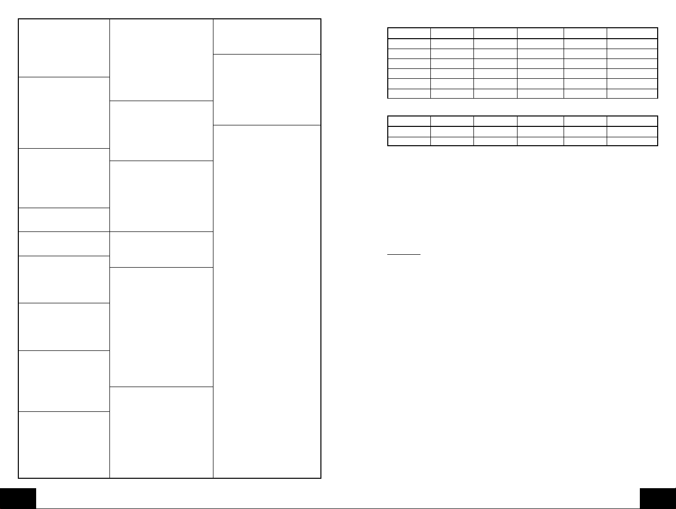
OK Oklahoma TX Texas (cont.) WV West Virginia
17K Boise City DFW Dallas/Ft. Worth CRW Charleston
LAW Lawton ELP El Paso HLG Wheeling
OKC Oklahoma City HOU Houston WY Wyoming
TUL Tulsa LRD Laredo BYG Buffalo
OR Oregon ODO Odessa CPR Casper
BNO Burns SAT San Antonio CYS Cheyenne
EUG Eugene UT Utah LAA Little America
MFR Medford SAL Saline WYE West Y ellowstone
PDX Portland SGU St. George
SLE Salem SLC Salt Lake City
PA Pennsylvania TSN Thompson
CXY Harrisburg VA Virginia
PHL Philadelphia DON Vienna
PIT Pittsburgh LYH Lynchburg
SCR Scranton ORF Norfolk
PR Puerto Rico RIC Richmond
SJU San Juan ROA Roanoke
RI Rhode Island VT Vermont
PVD Providence BTV Burlington
SC South Carolina MPR Montpelier
CHS Charleston WA Washington
CUB Columbia ABE Aberdeen
GMU Greenville ALW Walla W alla
SD South Dakota KTF Kettle Falls
FSD Sioux Falls MVN Mt. Vernon
PIR Pierre OLM Olympia
RAP Rapid City SEA Seattle
TN Tennessee SFF Spokane
BNA Nashville TON Tonasket
CHA Chattanooga YKM Yakima
DKX Knoxville WI Wisconsin
MEM Memphis AUW Wausau
TX Texas GRB Green Bay
ABI Abilene LSE La Crosse
AMA Amarillo MSN Madison
AUS Austin MWC Milwaukee
BRO Brownsville SSQ Spooner
Liste des villes du Canada
Code de l'Etat Code de Ville Code de l'Etat Code de Ville Code de l'Etat Code de Ville
EDM Edmonton YEL Yellowknife CHT Charlotte Town
ALB Calgary OTT Ottawa MON Montreal
VAN Vancouver SUD Sudbury QUE Quebec
WIN Winnipeg THU Thunder Bay REG Regina
FRE Fredericton TOR Toronto WHI Whitehorse
HAL Halifax
Liste des villes du Mexique
Code de l'Etat Code de Ville Code de l'Etat Code de Ville Code de l'Etat Code de Ville
CHH Chihuahua MEX Mexico City HER Hermosillo
DUR Durango GUA Guadalupe
E. Réglages du fuseau horaire et de l'heure d'été
1. Appuyer sur la touche "
2. Appuyer 9 fois sur la touche "
3. Le fuseau horaire clignote maintenant basé sur la ville sélectionnée.
4. Appuyer sur la touche "+"ou "-"et la relâcher pour ajuster le fuseau horaire correct.
5. Appuyer sur la touche "
d'été.
6. "dst ON" clignote maintenant.
7. Appuyer sur la touche "+" ou "-"et la relâcher pour sélectionner DST 1 (reconnaît le
changement d'heure d'été) ou DST 0 (ne change pas avec l'heure d'été).
Remarque
d'été.
8. Appuyer sur la touche "
F. Unités de mesure météo (˚F/˚C, inHg/hPa)
1. Appuyer sur la touche "
2. Appuyer 11 fois sur la touche "
3. Les unités de température sélectionnées clignotent maintenant (˚F par défaut/réglage
4. Appuyer sur la touche "+"ou "-" et la relâcher pour sélectionner ˚F (Fahrenheit) ou ˚C
5. Appuyer sur la touche "
6. Les unités de pression atmosphérique sélectionnée clignotent maintenant (inHg par
7. Appuyer sur la touche "+"ou "-"et la relâcher pour sélectionner inHg (pouces de mercure)
8. Appuyer sur la touche "
9. L'indication de la pression atmosphérique clignote maintenant (29.91 inHg, 1012.8
10. Appuyer sur la touche "+"ou "-"et la relâcher pour ajuster la pression atmosphérique
11. Appuyer sur la touche "
: Certaines régions (Arizona et des zones de l'Indiana) n'appliquent pas l'heure
mesure météo (sauter les étapes 1 et 2 dans la section E pour continuer)
d'origine).
(Celsius).
pression atmosphérique barométrique.
défaut/réglage d'origine).
ou hPa (hectopascal ou millibars).
de la pression atmosphérique barométrique.
hPa par défaut).
relative correcte, basée sur les rapports locaux.
de la prévision.
SET
" la maintenir enfoncée pendant 1 seconde.
SET
" et le relâcher.
SET
" et la relâcher pour avancer vers le réglage de l'heure
SET
" et la relâcher pour avancer vers le réglage des unités de
SET
" la maintenir enfoncée pendant 1 seconde.
SET
" et la relâcher.
SET
" et la relâcher pour avancer vers le réglage des unités de
SET
" et la relâcher pour avancer vers le réglage de l'étalonnage
SET
" et la relâcher pour avancer vers le réglage de la sensibilité
P.30
F
P.31
F

Remarque
"pression atmosphérique relative". Cette lecture est basée sur la combinaison de la pression
atmosphérique absolue et l'altitude. En général, une augmentation en altitude conduit à
une diminution de pression atmosphérique. La lecture de la pression atmosphérique relative
sera effectuée dans des localités relativement proches l'une de l'autre pour permettre
d'effectuer une prévision correcte. La lecture de la pression atmosphérique absolue dans
le centre météo ne peut pas être étalonnée, seulement la pression atmosphérique relative.
12. Le réglage de la sensibilité de prévision sélectionnée clignote maintenant (0.09 inHg
13. Appuyer sur la touche "+"ou "-"et la relâcher pour sélectionner 0.06, 0.09, ou 0.12 inHg
14. Appuyer sur la touche "
15. Le niveau d'avertissement d'orage sélectionné clignote maintenant (0.15 inHg, 5 hPa
16. Appuyer sur la touche "+"ou "-"et la relâcher pour sélectionner le réglage d'avertissement
17. Appuyer sur la touche "
18. Le réglage d'activation ou de désactivation d'avertissement d'orage clignote maintenant
19. Appuyer sur la touche "+"ou "-"et la relâcher pour sélectionner si l'alarme d'avertissement
20. Appuyer sur la touche "
G. Contraste LCD
1. Appuyer sur la touche "
2. Appuyer 17 fois sur la touche "
3. Le réglage du contraste LCD clignote maintenant (4 est le réglage par défaut/réglage
4. Appuyer sur la touche "+"ou "-" et la relâcher pour sélectionner le niveau de contraste
5. Appuyer sur la touche "
6. Le réglage LI clignote maintenant (ON est le réglage par défaut/réglage d'origine).
7. Appuyer sur la touche "+"ou "-" et la relâcher pour sélectionner ON ou OFF.
8. Appuyer sur la touche "
Remarque
présent uniquement pour une utilisation future.
: La pression atmosphérique barométrique est normalement signalée comme
par défaut).
(si hPa est sélectionné, les choix seront 2, 3 ou 4). Un réglage inférieur conduit à un
changement plus rapide dans l'icône de prévision. En d'autres termes, si le réglage est
0.06 inHg, l'icône de prévision change si la pression atmosphérique change d'au moins
0.06 inHg durant une période de six heures. C'est utile, car certaines régions ont un
changement de pression atmosphérique, mais pas de changement de temps.
l'avertissement d'orage.
par défaut).
d'orage. Ceci peut être réglé à 0.09, 0.12, 0.15, 0.18, 0.21, 0.24 ou 0.27 inHg (de 3 à
9 hPa). Ce réglage détermine quelle chute de pression atmosphérique sur six heures
va faire retentir l'alarme d'avertissement d'orage.
désactivation de l'alarme d'avertissement d'orage.
(AOFF par défaut/réglage d'origine).
d'orage doit être activée ou non.
les étapes 1 et 2 dans la section F pour continuer)
d'origine).
désiré (de 1 à 8).
: Le réglage LI n'affecte pas la fonction de la station météo intérieure et il est
SET
" et la relâcher pour avancer vers le réglage de
SET
" et la relâcher pour avancer vers le réglage d'activation/
SET
" et la relâcher pour avancer vers le réglage LCD (sauter
SET
" et la maintenir enfoncée pendant 1 seconde.
SET
" et la relâcher.
SET
" et la relâcher pour avancer vers le réglage LI.
SET
" et la relâcher pour quitter le mode de programmation.
CARACTERISTIQUES ET FONCTIONNEMENT
A. Calcul du lever/coucher du soleil et du lever/coucher de la lune
La station météo intérieure calculera le lever/coucher du soleil et le lever/coucher de la lune
chaque jour basé sur le lieu entré en mode de programmation. Pour visualiser un autre lieu
et/ou une autre date sans affecter la ville programmée et la date, suivre la section A.2 dans
Caractéristiques et fonctionnement.
1. Calcul des heures et minutes de l'heure d'été
Appuyer sur la touche "
du soleil apparaît le nombre d'heures et de minutes de l'heure d'été. Appuyer sur la touche
"
SUN/MOON
2. Visualiser des localités différentes /heure de lever/coucher du soleil et de lever/
coucher de la lune
Si aucune touche n'est en,foncée en 30 secondes pendant cette sélection la station météo
intérieure retourne au mode norma. En alternance, sur la touche "CH" peut être enfoncée
pour retourner au mode normal.
a. Appuyer sur la touche "
b. Le pays sélectionné clignote maintenant.
c. Appuyer sur la touche "+" ou "-" et la relâcher pour sélectionner le pays désiré.
d. Appuyer sur la touche "
e. L'état clignote maintenant.
f. Appuyer sur la touche "+" ou "-" et la relâcher pour sélectionner l'état (voir les listes
g. Appuyer sur la touche "
h. La ville clignote maintenant.
i. Appuyer sur la touche "+" ou "-" et la relâcher pour sélectionner la ville.
j. Appuyer sur la touche "
Si les heures de lever du soleil et de lever de la lune sont désirées pour la date courante,
la touche "
explication plus détaillée.
k. L'année clignote maintenant (l'année courante).
l. Appuyer sur la touche "+" ou "-" et la relâcher pour sélectionner l'année désirée.
m. Appuyer sur la touche "
n. Le mois clignote maintenant (le mois courant).
o. Appuyer sur la touche "+" ou "-" et la relâcher pour sélectionner le mois désiré.
p. Appuyer sur la touche "
q. La date clignote maintenant (la date courante).
r. Appuyer sur la touche "+" ou "-" et la relâcher pour sélectionner la date désirée.
s. Appuyer sur la touche "
A la place on peut appuyer sur la touché "
commençant par l'étape b ci-dessus.
t. Dès que la touche "
u. Dès que ce mode est quitté soit après un délai d'attente après 30 secondes soit en
" pour visualiser de nouveau l'heure de lever/coucher du soleil.
secondes.
de la ville si le Canada ou le Mexique est sélectionné, sauter vers l'étape h.).
pages 28 à 31).
SUN/MOON
de la ville à la date sélectionnée.
et de lever/coucher de la lune clignotent sous forme de traits pendant que la station
météo intérieure calcule les heures (la phase lunaire est calculée, également). Dès
que les heures sont affichées, la station météo intérieure reste dans ce mode pendant
30 secondes ou jusqu'à ce que la touche "CH" soit enfoncée. L'année, le mois ou la
date clignote également. A ce moment-là, il est possible de commencer par l'étape b.
pour sélectionner une autre date ou lieu.
appuyant sur la touché "CH", la station météo intérieure retourne au mode avec le lieu
et la date réglés à l'aide du mode de programmation. La station m étéo intérieure retourne
par défaut à la dernière ville sélectionnée lorsque ce mode est entré de nouveau.
SUN/MOON
" peut être enfoncée pour le calcul. Sauter vers l'étape t pour une
SUN/MOON
" et la relâcher. A la place de l'heure de lever/coucher
SUN/MOON
SET
SET
SET
SET
SET
SUN/MOON
" la maintenir enfoncée pendant au moins deux
" et la relâcher pour avancer vers la sélection de l'état (ou
" et la relâcher pour avancer vers la sélection de la ville.
" et la relâcher pour avancer vers le réglage de la date.
" et la relâcher pour avancer vers le réglage du mois.
" et la relâcher pour avancer vers le réglage de la date.
" et la relâcher pour calculer le nouvel emplacement
SET
" pour sélectionner un autre lieu, en
" est enfoncée, les heures de lever/coucher du soleil
P.32
F
P.33
F
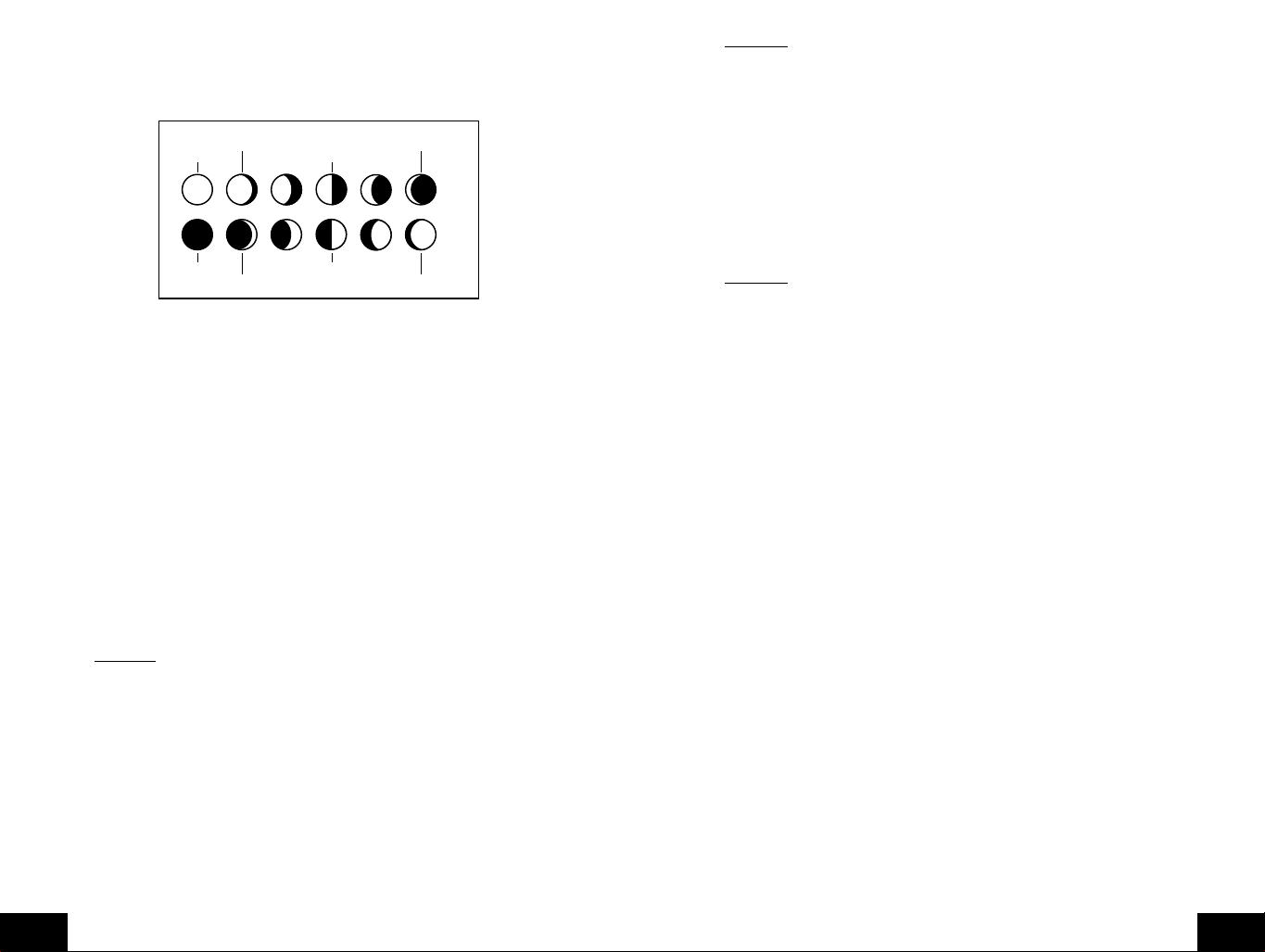
B. Phase lunaire
1. Il y a 12 phases lunaires affichées sur la station météo intérieure; la partie noire signifie la
partie de la lune visible au ciel. Ainsi, lorsque l'icône de lune est entièrement noire, c'est la
pleine lune. La station météo intérieure est programmée avec toutes les phases lunaires
de l'année 2000 jusqu'à 2099.
Lune croissante Lune croissante
Nouvelle Lune
Pleine Lune
Lune décroissante Lune décroissante
Premier quartier
Dernier quartier
2. La phase lunaire pour chaque date peut être trouvée en sélectionnant une date différente
par la section de programmation du lever/coucher du soleil et du lever/coucher de la lune
(section A dans Caractéristiques et fonctionnement).
C. Température mini et maxi et hygrométrie
1. Température intérieure mini et maxi et hygrométrie
La station météo intérieure mémorise automatiquement les températures mini et maxi
intérieure et l'hygrométrie. Les valeurs minima et maxima sont mises à jour automatiquement
lorsqu'un nouveau minimum ou maximum est enregistré ou jusqu'à la réinitialisation
manuelle.
a. A partir du mode d'affichage normal, appuyer une fois sur la touche "
IN
" et la relâcher
pour visualiser la température intérieure minimale et l'hygrométrie ("MIN" sera affiché
près de la température intérieure et l'hygrométrie).
b. Appuyer à nouveau sur la touche "
IN
" et la relâcher pour visualiser la température
maxi intérieure et l'hygrométrie.
c. Appuyer de nouveau sur la touche "
IN
" et la relâcher pour retourner au mode normal
(un délai d'attente de visualisation des valeurs mini/maxi s'instaure si aucune touche
n'est enfoncée pendant quinze secondes).
Remarque
valeurs de l'alarme sont affichées, "
: Le mode d'alarme de température partage le même affichage. Lorsque les
ALARM
" sera affiché au-dessus de la température
radio-pilotée. Pour effectuer un va-et-vient entre les affichages, appuyer sur la touche
"
OUT
".
c. Pour réinitialiser les températures extérieures mini et maxi appuyer sur la touche "
la maintenir enfoncée pendant au moins une seconde.
D. Capteurs de température radio-pilotés multiples
Le WS-8025SU est capable de recev oir des signaux de 3 capteurs r adio-pilotés différents.
Ces capteurs radio-pilotés supplémentaires peuvent être achetés auprès du même
revendeur de cet appareil. Un TX4U contrôle la température et l'hygrométrie, un TX3U
contrôle la température et affiche la température sur son écran LCD et le TX3UP contrôle
la température via une sonde de mesure des températures du sol ou de l'eau.
Remarque
: Lors de l'installation de plusieurs appareils, il est important d'insérer d'abord
les piles dans tous les capteurs radio-pilotés, et dans un ordre numérique. Ensuite, installer
les piles dans la station météo intérieure. Des problèmes de transmission se produiront si
ceci n'est pas effectué correctement et si la durée totale de l'installation dépasse 6 minutes
1. Installation de plusieurs appareils
a. Il est nécessaire de retirer les piles de tous les appareils en cours de service.
b. Retirer le couvercle du compartiment à piles de tous les capteurs radio-pilotés.
c. Placer tous les capteurs radio-pilotés dans un ordre numérique.
d. Installer les piles dans l'ordre en suivant les mêmes procédures d'installation des
piles décrites dans la section Guide d'installation détaillé de ce mode d'emploi.
e. Installer les piles dans la station météo intérieure.
f. Suivre le Guide d'installation détaillé pour la programmation et le mode d'emploi.
2. Visualiser et utilisation avec plusieurs capteurs radio-pilotés
a. Pour visualiser la température d'un autre capteur radio-piloté appuyer sur la touche
"
CHANNEL
" et la relâcher. Un décalage d'un nombre "encadré" vers le suivant
doit être observé sur l'écran LCD OUTDOOR.
b. Les températures mini et maxi du capteur radio-piloté supplémentaire sera affiché
sous la température actuelle du capteur radio-piloté sur l'écran LCD OUTDOOR.
c. Pour réinitialiser les relevés de températures mini et maxi, appuyer sur la touche
"
RESET
" la maintenir enfoncée pendant 5 secondes et les enregistrements pour
tous les capteurs radio-pilotés seront réinitialisés.
CH
"
Remarque
: Pour réinitialiser la température mini et maxi intérieure et l'hygrométrie, appuyer
sur la touche "IN" et la maintenir enfoncée pendant au moins deux secondes.
2. Température extérieure mini et maxi et hygrométrie
La station météo intérieure mémorise automatiquement la température mini et maxi
extérieure et l'hygrométrie. Les valeurs minimales et maximales sont mises à jour
automatiquement lorsqu'un nouveau minimum ou maximum est enregistré ou jusqu'à la
réinitialisation manuelle.
a. Les valeurs de température extérieure (radio-pilotée) mini et maxi sont affichées sous
l'affichage de température extérieure.
b. Ces valeurs sont arrondies vers le bas pour le minimum et arrondies vers le haut pour
le maximum.
P.34
F
Chaque capteur radio-piloté a ses propres valeurs minima et maxima mémorisées,
ainsi que ses propres réglages d'alarme pour la température. Le fait de réinitialiser les
valeurs de température extérieure mini et maxi réinitialisera tous les enregistrements
du capteur radio-piloté.
E. Alarme de température radio-pilotée
1. Activer l'alarme
En mode normal, appuyer sur la touché "
l'alarme de température et les valeurs mini/maxi. "
OUT
" et la relâcher pour commuter entre
ALARM
" sera affiché au-dessus de
l'affichage de la température radio-pilotée; ceci va également activer l'alarme de
température.
2. Réglage de l'alarme de température
a. Appuyer sur la touche "
OUT
" la maintenir enfoncée pendant deux secondes.
b. La basse température clignote (32˚F par défaut /réglage d'origine).
P.35
F
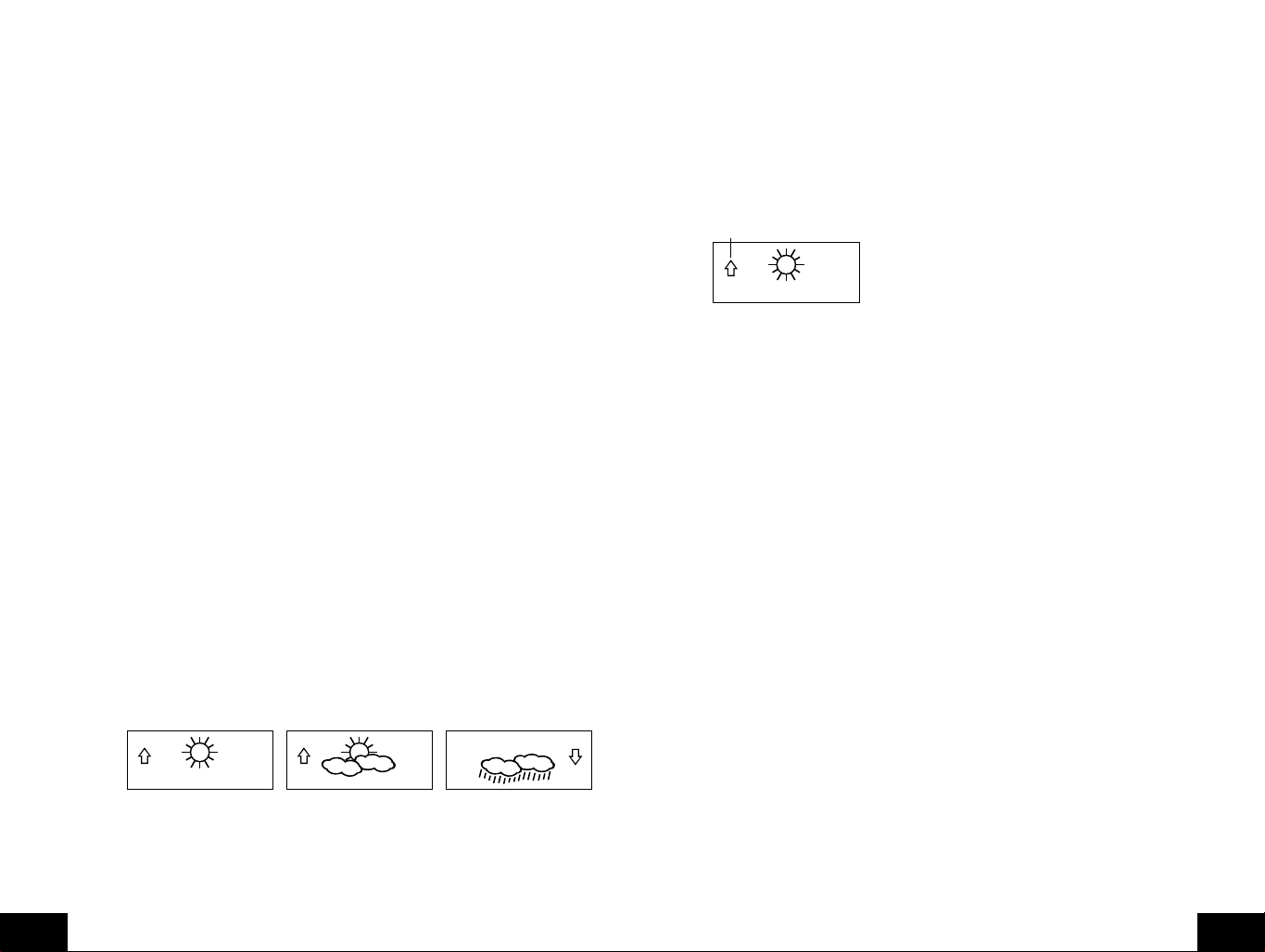
c. Appuyer sur la touche "+" ou "-" et la relâcher pour ajuster la température de -22˚F
Flèche de tendance de pression
à +157˚F ("- -" si hors de cet intervalle limite). Toute valeur inférieure à cette v aleur
fait retentir l'alarme.
d. Appuyer sur la touche "
température élevée.
e. Le réglage de température élevée clignote maintenant (86˚F par défaut/réglage
d'origine).
f. Appuyer sur la touche "+" ou "-" et la relâcher pour ajuster la température de -22˚F
to +157˚F ("- -" si hors de cet intervalle limite). Toute valeur supérieure à cette
valeur fait retentir l'alarme.
g. Appuyer sur la touche "
normal (ou l'affichage présente un délai d'attente après quinze secondes et retourne
automatiquement au mode normal).
3. Annuler l'alarme de température pendant sa sonnerie
a. Pendant la sonnerie de l'alarme, appuyer sur n'importe quelle touche pour rendre
l'alarme silencieuse. La température clignote aussi longtemps que la valeur est
supérieure à la valeur réglée.
b. L'alarme se réactive automatiquement dès que la valeur est descendue en dessous
de la valeur réglée ou si une nouvelle valeur est entrée.
F. Indicateur de niveau de confort pour la température intérieure et l'hygrométrie
1. L'indicateur de niveau de confort apparaît entre la température intérieure et l'hygrométrie.
2. L'indicateur affiche un "visage heureux" lorsque la température est comprise entre 68˚F
et 79˚F (20˚C et 25.9˚C), l'hygrométrie est comprise entre 45 % et 64 %.
3. Un "visage triste" est affiché lorsque la température et l'hygrométrie sont hord des
intervalles limites mentionnés.
4. Si l'hygrométrie est inférieure à 45 % le mot "DRY" apparaît à droite de l'icône "visage
triste".
5. Si l'hygrométrie est supérieure à 54 % le mot "WET" apparaît à droite de l'icône "visage
triste".
G. Icône de prévision météo et indicateurs de tendance de pression
La fonction de prévision météo a une précision estimée à 75 %, elle est basée uniquement
sur le changement de pression atmosphérique dans le temps. Le WS-8025SU fait la mo yenne
des relevés de pressions atmosphériques précédentes pour fournir une prévision précise-
créant la nécessité de ne pas tenir compte de toutes prévisions météo 12-24 heures après
l'installation, la réinitialisation ou le déplacement de l'appareil d'une altitude vers une autre
(i.e. d'un étage d'un immeuble vers un autre étage). Dans des régions où le temps n'est pas
affecté par le changement de pression atmosphérique, cette fonction sera moins précise.
1. Icônes météo
a. Il y a 3 icônes météo possibles qui seront affichées à différentes heures au centre de
la station météo intérieure.
i
Ensoleillé
sera ensoleillé).
ii
Soleil avec des nuages
temps sera ensoleillé sans nuages).
iii Nuages avec de la pluie-indique que le temps va se détériorer (cela ne signifie
pas que le temps sera pluvieux).
- indique que le temps va s'améliorer (cela ne signifie pas que le temps
SET
" et la relâcher pour avancer pour vers l'alarme de
SET
" et la relâcher pour retourner au mode d'affichage
- indique que le temps moyen (cela ne signifie pas que le
b. Les icônes météo changent lorsque l'appareil détecte un changement de pression
atmosphérique.
c. Les icônes changent dans l'ordre, de "ensoleillé" à "soleil avec des nuages" à "nuages
avec de la pluie " ou l'inverse.
d. Il ne change pas de "sunny" directement à "nuages avec de la pluie ", bien qu'il soit
possible que le changement se produiise rapidement.
e. Si les symboles ne changent pas, le temps n'a pas changé (ou le changement a été
lent et progressif).
f. La sensibilité du changement dans l'icône de prévision est réglé par l'utilisateur dans
la section F du Guide d'installation détaillé.
H. Flèches de tendance météo
1. Le long de l'icône de prévision il y a une flèche de tendance de pression.
2. Une flèche pointe vers le haut (à gauche de l'écran LCD) et une autre pointe vers le bas
(à droite de l'écran LCD).
3. Ces flèches reflètent les changements actuell de la pression atmosphérique.
4. Une flèche qui pointe vers le haut indique que la pression atmosphérique est en cours
d'augmentation et que le temps va s'améliorer ou rester stable.
5. Une flèche qui pointe vers le bas indique que la pression atmosphérique est en cours de
diminution et que le temps va se détériorer ou rester médiocre.
6. Aucune flèche signifie que la pression est stable.
7. Un orage peut être attendu s'il y a une chute de pression de 4 hPa ou plus en moins de
6 heures. L'icône nuages avec de la pluie sera affichée et la flèche de tendance qui
pointe vers le bas clignote-indiquant que la fonction d'avertissement d'orage a été activée.
Le clignotement s'arrête lorsque la pression atmosphérique se stabilise ou commence à
monter.
I. Alarme d'avertissement d'orage
1. Une alarme peut être programmée pour avertir une chute de la pression atmosphérique.
2. Suivre les instructions de programmation dans la section F du Guide d'installation détaillé
pour activer cette alarme
3. Lorsque la pression atmosphérique chute au niveau réglé, une alarme retentit (si l'alarme
est activée).
4. Pour annuler l'alarme pendant sa sonnerie, appuyer sur n'importe quelle touche.
J. Tendance de la pression atmosphérique pour les deux dernières heures
La barre sous le graphique d'historique de la pression atmosphérique affiche le changement
de pression atmosphérique sur les deux dernières heures (valeurs basées sur le changement
de hPa, 1 hPa est égal à 0.03 inHg).
K. Lecture de la pression atmosphérique barométrique
1. La pression atmosphérique barométrique effective est affichée directement sous l'icône
de prévision météo.
2. La pression atmosphérique relative est étalonnée par l'utilisateur à l'aide du mode de
programmation.
3. Suivre les instructions de programmation dans la section F du Guide d'installation détaillé
pour régler cette fonction.
4. Pour commuter entre les pressions atmosphériques absolue et relative, appuyer sur la
touche "-".
P.36
F
P.37
F
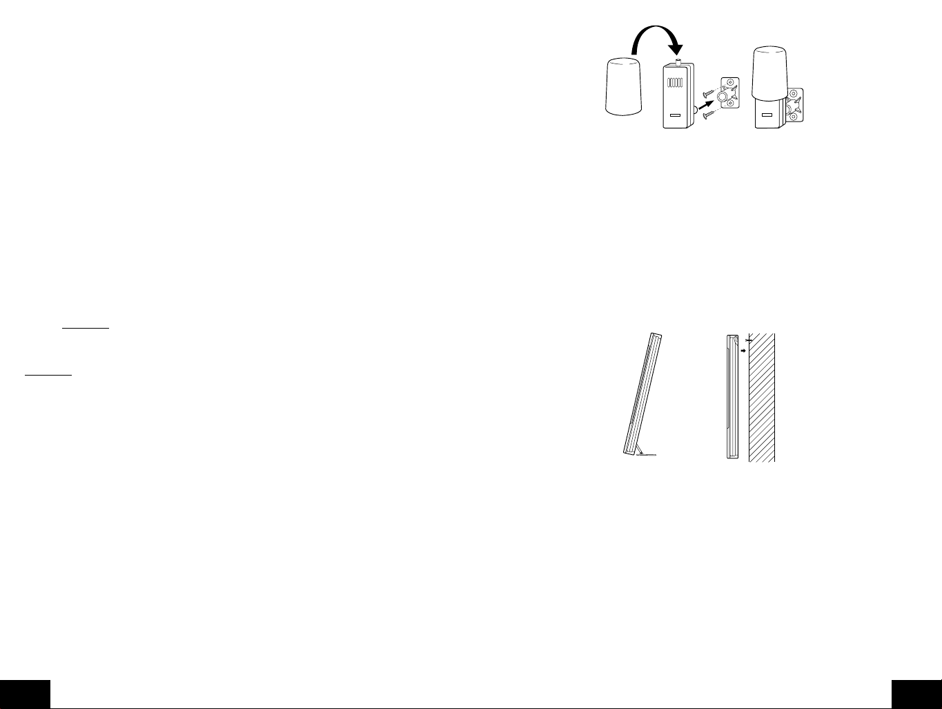
L. Graphique d'historique de la pression atmosphérique
1. Le graphique indique en hPa (Hekto Pascal) la pression atmosphérique enregistrée les
30 dernières heures.
2. L'axe horizontal indique les heures par incréments de -30 heures, -24 heures, -18 heures,
-12 heures, -6 heures, -3 heures, -1 heures, et 0 heure (courante).
3. L'axe vertical est réglé par hPa: "0" sur cet axe représente la valeur courante en hPa, et
+ ou - 1,3,5 ou 7 indique (in hPa) la pression atmosphérique précédente haute ou basse
comparée à la pression actuelle.
4. "0" sur l'axe vertical indique la valeur de la pression atmosphérique actuelle.
5. "0h" sur l'axe horizontal indique l'heure courante, donc aussi la pression atmosphérique
actuelle.
6. Chaque barre sur le graphique représente une valeur de 0,03 hPa, et chaque barre a
également une valeur correspondante sur l'axe vertical.
7. Les tendances de pression atmosphérique peuvent être déterminées en regardant
simplement sur le graphique à barres.
a. Si les barres sont en train de monter (plus haut à droite qu'à gauche), la pression
atmosphérique a alors tendance à monter, et le temps doit s'améliorer.
b. Si les barres sont en train de chuter (plus bas à droite qu'à gauche), la pression
atmosphérique a alors tendance à baisser, et le temps doit se dégrader.
8. Multiplier les deux valeurs pour trouver la pression atmosphérique précédente (noter le
signe + ou - des valeurs sur l'axe vertical); i.e. 0.03 hPa x 3 = 0.09 hPa, maintenant
ajouter cette valeur à la pression atmosphérique (sur l'écran LCD 4) pour évaluer les
pressions atmosphériques précédentes.
9. Le graphique à barres va défiler constamment pour éviter de griller l'écran LCD.
Remarque
: Cette fonction ne peut pas être désactivée.
MONTAGE
Remarque
recevoir des signaux des émetteurs et de la station WWVB à l'endroit désiré. Pour obtenir un relevé
de température effective , éviter de monter le capteur thermo/hygro r adio-piloté (ou tout autre capteur)
dans un endroit ou les rayons du soleil peuvent atteindre le capteur radio-piloté. Il est recommandé
de monter le capteur radio-piloté sur un mur face au nord ou sous abri. La portée de transmission du
capteur thermo/hygro radio-piloté est de 200 pieds(60 m) toutefois, des obstacles , tels que des murs ,
du béton, et de gros objets métalliques peuvent réduire la portée. Placer tous les appareils sur leurs
emplacements désirés et attendre environ 15 minutes av ant de les monter définitiv ement afin d'assurer
une réception correcte. Si la station météo intérieure perd le signal du capteur radio-piloté, il affichera
la dernière température lue pendant 15 minutes. Après 15 minutes sans réception de signaux, la
température radio-pilotée affiche "- -.-".
F
: A vant de monter définitivement, s'assurer que la station météo intérieure est capable de
A. Montage du capteur thermo/hygro radio-piloté
Le capteur thermo/hygro radio-piloté peut être monté à l'aide de vis ou en utilisant le ruban
adhésif.
1. Montage à l'aide de vis
a. Retirer le support de montage/récepteur de l'emballage.
b. Placer le support de montage par dessus la surface de montage désirée.
c. A travers les 2 trous de vis du support, marquer la surface de montage avec un crayon.
d. A l'endroit marqué, faire des trous de vis en utilisant les vis fournies.
e. Retirer les vis de la surface de montage.
f. Aligner le support de montage avec les trous de vis.
g. Visser le support de montage sur la surface de montage. Les vis doivent être à ras
avec le support.
h. Fixer le pilier de montage (au dos de l'émetteur) dans le récepteur du support de
montage.
P.38
REMOTE
THERMO-SENSOR
433 MHz
REMOTE
THERMO-SENSOR
433 MHz
2. Montage à l'aide d'un ruban adhésif
a. En utilisant une solution non abrasive, nettoyer et sécher le dos du support de montage
et de la surface de montage pour assurer une fixation solide. La surface de montage
doit être lisse et plate.
b. Retirer la bande de protection d'une face de la bande.
c. Enfoncer fermement la zone désignée au dos du support de montage.
d. Retirer la bande de protection de l'autre face de la bande, et fixer le support de montage.
e. Enfoncer fermement le support de montage sur la surface de montage.
f. Fixer le pilier de montage dans le récepteur du support de montage.
B. Montage du centre météo WS-8025SU
La station météo intérieure peut être montée de deux manières; debout ou en suspension au
mur.
Pour mettre la station météo intérieure debout, déplier simplement les pieds au dos et la
placer sur une surface plate stable.
Pour monter la station météo intérieure au mur;
1. S'assurer que les pieds intégrés sont pliés.
2. Fixer une vis (non fournie) dans le mur désiré, en laissant environ 3/16 pouces (5 mm) du
mur.
3. Placer la station météo intérieure sur la vis en utilisant le trou de suspension au dos. Tirer
doucement la station météo intérieure vers le bas pour verrouiller la vis en place.
ENTRETIEN
A. Eviter les changements excessifs de température, vibrations et chocs qui endommageraient les
appareils.
B. Nettoyer les affichages et appareils av ec un chiff on doux et humide . Ne pas utiliser de dissolvants
ni de produits abrasifs - ils risquent de les rayer. Ne pas plonger les appareils dans de l'eau.
C. Retirer sans délai toutes piles faibles afin d'éviter fuites et dégâts. Remplacer les piles par des
piles neuves de la taille recommandée.
D. Ouvrir les boîtiers risque d'annuler la garantie. Ne pas essayer de réparer l'appareil. Pour toutes
réparations, contacter La Crosse Technology.
P.39
F

EN CAS DE PANNE
Problème : Le LCD est pâle.
Solution :1)Règler le contraste à un niveau plus élevé.
2) Remplacer les piles.
Problème : Pas d'affichage de la température/humidité.
Solution : 1) Retirer toutes les piles; les remettre en commençant par l'émetteur, suivi du Centre
Météo.
2) Rapprocher l'émetteur à distance de l'afficheur.
3) S'assurer que toutes les piles sont bonnes.
4) S'assurer de l'absence de sources d'interférence dans le voisinage (moniteurs
d'ordinateurs, téléviseurs, casques ou haut-parleurs). Le signal voyage en ligne droite
et une source électrique près de cette "ligne" peut causer des interférences.
Problème : La température, l'humidité ou la pression atmosphérique sont incorrectes.
Solution :1)Vérifier/remplacer les piles.
2) Si plusieurs émetteurs sont utilisés, vérifier leur position avec les "numéros encadrés"
correspondant.
3) Eloigner les appareils des sources de chaleur/froid.
4) Ajuster la pression atmosphérique relative sur une valeur d'une source fiable
télévision, radio, etc.).
5) Le Centre Météo et les émetteurs sont calibrés en usine. En cas de persistance du
problème, contacter La Crosse Technology.
Problème : "--" sur l'affichage de l'humidité.
Solution : 1) L'humidité est inférieure à 1% ou supérieure à 99%.
2) Un TX3U ou TX3UP est utilisé pour la température à distance.
Problème : L'heure et la date WWVB ne se règlent pas ou ne s'actualisent pas.
Solution : 1) Attendre le signal nocturne.
2) Eloigner le Centre Météo de sources électriques.
3) Placer le Centre Météo à une fenêtre tournée vers le Colorado.
4) La première réception est la plus difficile, car le Centre Météo a besoin de recevoir un
signal clair pendant cinq minutes. Après le réglage initial de l'heure/date, il lui suffit
d'une minute de réception claire chauqe nuit.
SPECIFICATIONS
Signal horaire radio-commandé WWVB, 60 kHz de Ft. Collins, CO
Centre Météo - température de fonctionnement
recommandée0˚C à 50˚C (32˚F à 122˚F)
Contraste du LCD 8 niveaux (1-8)
Coucher/lever du soleil et de la lune et phases
de la lune disponibles 1er janvier 2000 au 31 décembre 2099
Rayon de relevés de température
Intérieure -9,9˚C à 59,9˚C à 0,1˚C près (14˚F à 140˚F à
0,2˚F près) ("OFL" affiché en-dehors de ces
limites)
Extérieure -29,9˚C à 69,9˚F à 0,1˚C près (-21,8˚F à
157,8˚F à 0,2˚F près) ("OFL" affiché en-dehors
de ces limites)
Rayon d'humidité relative
Intérieure/extérieure 1% à 99% à 1% près. Affiche "--.-" en-dehors
de ce rayon.
Pression atmosphérique
hPa/inHg absolus 700 hPa à 1099 hPa
(20,67 inHg à 32,46 inHg)
hPa relatifs (réglables) 960 hPa à 1040 hPa
inHg relatifs (réglables) 28,60 inHg à 30,45 inHg
Réglage de la sensibilité hPa 1hPa à 4hPa
Historique de la pression atmosphérique Pour les 30 dernières heures (0, -1, -1, -3, -6,
-12, -18, -24 et -30 heures).
Intervalles de relevé des données
Température intérieure Toutes les 15 secondes
Humidité intérieure Toutes les 20 secondes
Température extérieure Toutes les 5 minutes
Humidité extérieure Toutes les 5 minutes
Actualisation des relevés de l'émetteur (dans capteur)
Température extérieure Toutes les minutes
Humidité extérieure Toutes les minutes
Fréquence de transmission 433.92 MHz
Rayon de transmission 60m (200 pieds) en espace decouvert
Alimentation
Centre Météo 3 piles AA (IEC LR6) 1,5V
Emetteur thermo-hygro 2 piles AA (IEC LR6) 1,5V
GARANTIE
La Crosse Technology, Ltd garantit ce produit de façon limitée pendant 1 an contre les défauts de
fabrication et de matière.
Cette garantie limitée commence le jour du premier achat, n'est valable que pour les produits achetés
et utilisés en Amérique du Nord et ne couvre que l'acheteur originel de ce produit. Pour toute
intervention sous garantie, l'acheteur doit contacter La Crosse Technology, Ltd pour l'identification du
problème et les procédures de SAV. Les interventions sous garantie ne peuvent être effectuées que
dans un centre de SAV agréé par La Crosse Technology, Ltd. Le ticket de caisse d'origine doit être
présenté sur demande à La Crosse Technology, Ltd ou à son centre de SAV comme preuve d'achat.
La Crosse Technology, Ltd réparer a ou remplacera, à notre discrétion, ce produit g ratuitement comme
spécifié par la présente avec ou par des pièces ou produits neufs ou remis à neuf si ce produit
s'avère être déf ectueux pendant la période de la garantie limitée e xposée ci-dessus. Toutes les pièces
et produits remplacés deviennent la propriété de La Crosse Technology, Ltd et doivent être restitués
à La Crosse Technology, Ltd. Les pièces et produits de rechange sont couverts par la garantie d'origine
restante ou pendant quatre-vingt-dix (90) jours, soit la durée la plus longue. La Crosse Technology,
Ltd prendra en charge tous les frais de main d'œuvre et de matériels pour toute réparation couverte
par cette garantie. Si les réparations nécessaires ne sont pas couvertes par cette garantie ou s'il
s'avère, lors de sa vérification, qu'un produit ne nécessite aucune répar ation, la réparation ou vérification
vous sera facturée. Le propriétaire doit prendre en charge tous frais d'expédition du produit La Crosse
Technology, Ltd vers le centre de SAV agréé La Crosse Technology, Ltd. La Crosse Technology, Ltd
prendra en charge les frais raisonnables de retour au propriétaire du produit.
P.40
F
P.41
F

TABLE OF CONTENIDO
Tema Página
Inventario de Contenido/ Equipo Adicional 45
Acerca de la WWVB 45
Guía Rápida de Puesta en Funcionamiento 45
Guía Detallada de Puesta en Funcionamiento 46
Instalación de las Baterías 46
Secuencia de Puesta en Funcionamiento 47
Explicación de la Información de la Pantalla LCD 48
Esquema de las Teclas de Funcionamiento 48
Modo de Programación
Ajuste de Hora, Modo 12/24 Horas y Fecha 49
Ajuste de la Localización de la Ciudad 49
Códigos de Ciudades de Estados Unidos 50
Códigos de Ciudades de Canadá 53
Códigos de Ciudades de Méjico 53
Ajuste de Zona Horaria 53
Ajuste de la Hora de Verano (DST) 53
Unidades de Medición del Tiempo 53
Contraste de la Pantalla LCD 54
Características y Operación 54
Salida/Puesta del Sol y Cálculo de la Salida/Puesta de la Luna 54
Fase Lunar 56
Minimo/máximo de temperatura/humedad 56
Transmisores múltipes remotos 57
Alarma de temperatura remota 57
Indicador de comodidad 58
Ícono de pronóstico del tiempo y tendencia de presion 58
Flechas de tendencia del tiempo 59
Alarma de advertencia de tormenta 59
Tabla de la tendencia de la presion atmosferica en dos horas 59
Lectura de la presion atmosferica barométricaa 59
Tabla historica de la presion atmosferica 59
Montaje 60
Mantenimiento y cuidado 61
Guia de solucion de problemas 62
Especificaciones 62
Informacion de la garantia 63
INVENTARIO DE CONTENIDO
1. Estación del Tiempo Interior- WS-8025SU
2. Sensor hygro-térmico (temperatura/humedad) remoto- TX4U
3. Manual de Instrucciones y tarjeta de garantía
RADIO CONTROLLED
TIME DATE
WWWB
MOONRISE +1
SUNRISE MOON PHASE
PM PM
LOCATION MOONSET
SUNSET
HUMIDITY
INDOOR TEMPERATURE
TENDENCY
PRESSURE
PRESSURE HISTORY
OUTDOOR TEMPERATURE
LO
48
REMOTE
THERMO-SENSOR
433 MHz
MINHIMAX
%
RH
rel
inHg
+7
+5
+3
+1
0
-1
-3
-5
-7
-1h-3h-6h-9h-12h-18h-24h-30h
01
+4
+2
+1
+0.5
+0.2
0
HUMIDITY
%
2
RH
%RH%
RH
MIN MAX
SUN/
IN
MOON
OUT
CH
ALARM
+
SET
–
EQUIPO ADICIONAL (no incluido)
1. Cinco baterías AA nuevas de 1.5V alcalinas.
2. Un tornillo de Montaje en Pared (opcional)
ACERCA DE LA WWVB (Hora Radiocontrolada)
El NIST (Instituto Nacional de Estándares y Tecnología- Division de Hora y Frecuencia) la radio
estación WWVB está localizada en Ft. Collins, Colorado, y transmite la señal de hora exacta
continuamente a lo largo de los Estados Unidos a 60 kHz. La señal puede ser recibida a más de
2000 millas de distancia a través de la antena interna de la Estación del Tiempo. Sin embargo,
debido a la naturaleza de la Ionosfera de la tierra, la recepción es muy limitada durante las horas
diurnas. La Estación del Tiempo buscará la señal cada noche cuando la recepción es mejor. La
radio estación WWVB deriva su señal del Reloj Atómico del NIST en Boulder, Colorado. Un grupo de
Físicos Atómicos están midiendo continuamente cada segundo, de cada día, con una exactitud de
un diez billonésimos de segundo por día. Estos Físicos han creado un estándar internacional, midiendo
cada segundo como 9,192,631,770 vibraciones de un átomo de Cesio-133 al vacío. Para más
información acerca de la WWVB por favor visite el sitio web del NIST http://www.boulder.nist.gov/
timefreq/stations/wwvb.htm
GUIA RAPIDA DE PUESTA EN FUNCIONAMIENTO
Recomendación : Use Baterías Alcalinas de buena calidad y evite usar baterías recargab les.
1. Coloque La Estación del Tiempo Interior y el sensor hygro-térmico remoto separados 3 a 5 pies .
2. Debe sacarse las baterías de ambas unidades por 10 minutos.
3. Coloque las baterías en el sensor hygro-térmico remoto primero y luego en la Estación del Tiempo
Interior.
(Todos los sensores hygro-térmicos remotos deben ponerse en funcionamiento antes que la
Estación del Tiempo Interior)
4. NO PRESIONE NINGUNA TECLA POR 10 MINUTOS.
En este momento la Estación del Tiempo Interior y el sensor hygro-térmico remoto empezarán a
interactuar el uno con el otro y La Estación del Tiempo Interior presentará la temperatura y humedad
interior, la temperatura y humedad al aire libre. Si la Estación del Tiempo Interior no presenta todos
lo valores después de 10 minutos por favor reintente la puesta en funcionamiento anteriormente
descrita. Después que todos los valores son visualizados por 10 minutos usted puede colocar su
sensor hygro-térmico remoto al aire libre y ajustar la hora.
P.44
S
P.45
S
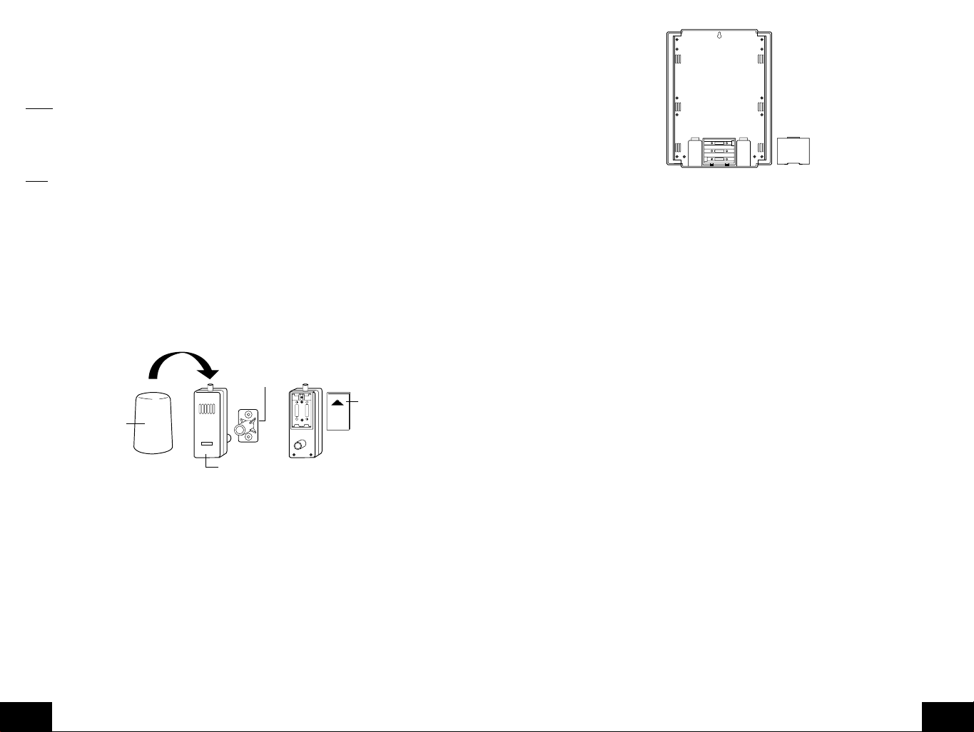
El sensor hygro-térmico remoto deberá ser colocado en un área seca y sombreada. El sensor h ygro-
+
SIZE AA LR6
+
SIZE AA LR6
+
SIZE AA LR6
térmico remoto tiene un rango de 200 pies. Cualquier pared que la señal tenga que atr av esar reducirá
su alcance. Una pared aire libre o una ventana tienen de 20 a 30 pies de resistencia y una pared
interior tendrá de 10 a 20 pies de resistencia. Su distancia más la resistencia no deberá e xceder los
200 pies en línea recta.
NOTA
: La niebla y el rocío no dañarán su sensor hygro-térmico remoto pero la lluvia directa debe
evitarse.
Para una puesta en funcionamiento completa de su Estación del Tiempo después que hayan pasado
10 minutos siga los pasos de la Guía Detallada de Puesta en Funcionamiento.
Nota
: El sensor hygro-térmico remoto transmite la señal cada 5 minutos; después que las baterías
ha sido instaladas, La Estación del Tiempo buscará la señal por espacio de 5 minutos. Si no hay una
lectura de temperatura en el AL AIRE LIBRE LCD después de 5 minutos, asegúrese que las unidades
están dentro del rango una de otra, o repita el procedimiento de Instalación de las Baterías.
GUIA DETALLADA DE PUESTA EN FUNCIONAMIENTO
I. Instalación de las Baterías
Las Baterías se ajustarán perfectamente. Para evitar problemas de arranque, asegúrese que
las baterías no salten de los contactos. Asegúrese también de insertar primero las baterías
alcalinas en el sensor hygro-térmico remoto, luego en la Estación del Tiempo Interior. La
puesta en funcionamiento inicial debe ser hecha con el sensor hygro-térmico remoto y la
Estación del Tiempo Interior en el mismo cuarto. Las unidades únicamente se montarán
permanentemente después que la recepción de la señal ha sido verificada.
Mounting
Bracket/Recent
Rain
Cover
REMOTE
THERMO-SENSOR
433 MHz
Thermo-Hygro
Transmitter
A. Sensor Remoto de Temperatura y Humedad, TX4U
1. Hale para quitar la cubierta cilíndrica para lluvia del transmisor.
2. Quite la tapa de las baterías (localizada en la parte trasera del transmisor, arriba del
poste de montaje y soporte). Presione la flecha y deslice la tapa de las baterías hacia
afuera.
3. Observando la polaridad correcta instale 2 baterías alcalinas AA.
4. Coloque nuevamente tapa de las baterías y coloque la cubierta de lluvia ajustadamente
en el transmisor.
B. Centro del Tiempo
1. Quite la tapa de las baterías (la cubierta tiene una inscripción blanca en ella).
2. Observando la polaridad correcta, instale tres baterías alcalinas AA.
3. No presione ninguna tecla por al menos diez minutos. Si una tecla es presionada
antes que la Estación del Tiempo hay a recibido información del sensor TX4U , ningún
dato será recibido hasta que el sensor se reinicialice.
4. Coloque nuevamente la tapa de las baterías.
P.46
S
+
SIZE AA LR6
SIZE AA LR6
+
Battery
Cover
II. Secuencia de Puesta en Funcionamiento
A. Initial Start
1. Inmediatamente después que las baterías han sido instaladas, en la Estación del Tiempo
Interior sonará un "beep", y el LCD se iluminará completamente por un breve momento.
2. Toda la información aparecerá luego en el modo normal, con "12:00" como la hora por
defecto y "1.1" como la fecha por defecto (2001 como el año).
3. "DCA" es la ciudad por defecto (Washington, DC, USA), con las horas de salida de
sol, puesta de sol, salida de luna y puesta de luna visualizadas para esa Ciudad y
fecha.
4. La temperatura interior, humedad y presión atmosférica barométrica (29.91 inHg como
RH relativa) también será visualizada.
5. Un ícono de "satélite" aparecerá cerca de la parte inferior LCD, a la derecha del "max"
de temperatura remota-este ícono informa que el usuario de la Estación del Tiempo
Interior está buscando la señal del sensor hygro-térmico remoto. Dentro cinco minutos
la temperatura remota y humedad deberán ser visualizadas-si no es así, quite las
baterías de todas las unidades y repita la instalación de las baterías, el sensor remoto
temperatura primero, luego la Estación del Tiempo Interior.
B. Recepción de la WWVB
1. Una vez que las baterías están instaladas en la Estación del Tiempo, esta empezará
automáticamente la búsqueda de la señal WWVB. Si recibe una buena señal (la cual
es muy difícil durante las horas diurnas en muchas localizaciones), el indicador de
recepción WWVB (parece un icono de la torre) titilará. La Estación del Tiempo Interior
requiere cinco minutos completos para que la recepción detecte exitosamente la señal
y ajuste la hora, minuto, segundo, mes, día y año correctos. Si la recepción de la señal
no es exitosa dentro de diez minutos, la búsqueda de la señal será cancelada y se
reintentará automáticamente cada dos horas hasta que la búsqueda de señal sea
exitosa.
2. La señal es enviada desde Ft. Collins, Colorado únicamente y es similar a una señal
de radio de AM. interferencias atmosféricas como tormentas, manchas solares, y aún
la luz solar causará que la señal no viaje tan lejos.
3. Para maximizar la recepción, coloque la Estación del Tiempo Interior en una v entana
orientada a Colorado y al menos a seis pies de cualquier fuente eléctrica
(computadores, televisores, refrigeradores, etc.). No mueva la Estación del Tiempo
Interior mientras esté buscando la señal.
4. La hora y fecha pueden ser manualmente ajustadas. Una vez la señal es detectada,
reemplazará cualquier hora y fecha ajustada ala Zona Horaria seleccionada.
5. Una vez que la hora y fecha son ajustadas, la Estación del Tiempo Interior conducirá
una búsqueda cada noche a medianoche para mantener la exacta hora y fecha (la
Hora de Verano es automática). Si la señal ha sido recibida en las pasadas 24 horas,
el indicador de recepción será visualizado.
P.47
S

III. Explicación de la Información de la Pantalla LCD
A. La siguiente ilustración presenta las características de la LCD
Indicador de recepción de la
área o ubicación seleccionada
área o ubicación seleccionada
Código de la ciudad para la ciudad
seleccionada (Aparecen visualizadas
Flecha para indicar las tendencias
de la presión del aire (Aparece
visualizada hacia arriba/ aumentando)
Selección de la presión del aire se puede
escojer en una escala de Absoluto o Relativo
(Aparece visualizado el modo Relativo)
Cambio de la Presión en las
(Aparece visualizado -4 hPa)
Temperatura a control remoto
Mínimos y máximos registros de
remoto o ajuste de la Alarma
WWVB señal
Hora controlada por
señales de radio
Hora del Amanecer para el
Hora del Atardecer para el
las siglas de San Francisco)
Temperatura en interiores
Visualización Barométrica
de la presión del aire
últimas 2 horas (in hPa)
la Temperatura a control
TIME DATE
WWWB
SUNRISE MOON PHASE
PM PM
INDOOR TEMPERATURE
TENDENCY
PRESSURE
PRESSURE HISTORY
OUTDOOR TEMPERATURE
LO
MIN
SUNSET
LOCATION MOONSET
rel
HI
MAX
0
+0.2
2
MIN MAX
+0.5
MOONRISE +1
HUMIDITY
inHg
+1
HUMIDITY
%RH%
Indicador de la Alarma
Fecha controlada por señales de radio
Hora de la aparición o salida de la luna
en el área o ubicación seleccionada
Fase de la luna actual/del momento
Hora en que se oculta la luna
en el área o ubicación seleccionada
%
Humedad en Interiores
RH
Icono del nivel de comodidad
Icono del pronóstico del tiempo
Unidad de medición para la
presión del aire (Aparece
visualizado en inHg)
+7
+5
+3
+1
0
Visualización gráfica de la
-1
-3
presión del aire en las
-5
-7
01
+4
%
RH
RH
últimas 30 horas
Humedad a Control Remoto
Número del Sensor a Control
Remoto (Hasta un total de 3)
Mínimos y máximos registros
de la Humedad a control remoto
-1h-3h-6h-9h-12h-18h-24h-30h
+2
B. Hay muchos diferentes modos en que la Estación del Tiempo Interior pueden ajustarse.
La LCD presenta el modo de operación normal, y sus datos actuales serán diferentes
basados en sus ajustes y condiciones locales.
IV. Esquema de las Teclas de Funcionamiento
A. La siguiente ilustración muestra las ocho teclas de funcionamiento usadas en la
programación y operación de su Estación del Tiempo Interior.
MIN MAX MIN MAX
IN
OUT
ALARM
SET
MOON
SUN/
CH
+
–
V. Modo de Programación
El Modo de Programación se ha puesto de una manera que le permite programar cada función
separadamente, o usted puede seguir las instrucciones completas para programar el centro
del tiempo interior. La programación completa normalmente se hace para la puesta en
funcionamiento inicial, y le exigirá que salte paso 1 y 2 de cada sección de la programación.
El modo de programación puede terminarse en cualquier momento presionando la tecla
marcada con "CH", o esperando 16 segundos que termine el efecto.
A. Repaso de la secuencia del modo de programación
Nota
: Si el ajuste de país es diferente a USA vaya al paso 8 Ciudad, paso 9 es Zona
Horaria, etc.
1. Hora 2. Minuto 3. 12/24 hora 4. Ano
5. Mes 6. Fecha 7. Pais 8. Estado
9. Ciudad 10.Zona Horaria 11.DST on/off 12. ˚F/˚C
13. inHg/hPa 14. Ajuste de la Presion 15. Pronostico de 16. Ajuste de la
Relativa Sensiblidad Advertencia
de T ormenta
17. Alarma de 18. Contraste de la 19. LI on/off
Tormenta Pantalla LCD
on/off
B. Ajuste de Hora, Modo 12/24 Horas y Fecha
La señal WWVB reemplazará cualquier ajuste de hora y fecha hecho manualmente. La
hora se basará en la Zona Horaria seleccionada.
1. Presione y sostenga la tecla "
SET
" por 1 segundo.
2. La hora está ahora titilando.
3. Presione y suelte la tecla "+" o "-" para seleccionar la hora actual.
Nota
: En el modo 12h “PM” aparecerá a la izquierda de la hora durante las horas de PM.
Si las horas no están dentro de las horas PM nada será visualizado. Asegúrese de ajustar
la hora a la correcta AM/PM para asegurar la recepción automática.
4. Presione la tecla "
SET
" para avanzar al minuto
5. El minuto está ahora titilando.
6. Presione y suelte la tecla "+"o "-" para seleccionar el minuto actual.
7. Presione y suelte la tecla "
SET
" para avanzar al ajuste del formato 12/24-hora.
8. "12" está ahora titilando.
9. Presione y suelte la tecla "+"o "-" para seleccionar el formato 12 (am/pm) o 24 (militar)
de horas.
10. Presione y suelte la tecla "
SET
" para avanzar al ajuste del año.
11. El año está ahora titilando.
12. Presione y suelte la tecla "+"o "-" para seleccionar el año actual.
13. Presione y suelte la tecla "
SET
" para avanzar al ajuste del mes.
14. El mes está ahora titilando.
15. Presione y suelte la tecla "+"o "-" para seleccionar el mes actual.
16. Presione y suelte la tecla "
SET
" para avanzar al ajuste de la fecha.
17. La fecha está ahora titilando.
18. Presione y suelte la tecla "+"o "-" para seleccionar la fecha actual.
19. Presione y suelte la tecla "
SET
" para avanzar al ajuste de la localización (vaya a los 1
y 2 en la sección en B si continúa).
C. Ajuste de la Localización de la Ciudad
La lista de las ciudades disponibles se lista después de esta sección.
1. Presione y sostenga la tecla "
2. Presione y suelte la tecla "
SET
SET
" 6 veces.
" por 1 segundo.
3. La localización del país titilará (USA por defecto/ ajuste de fábrica).
4. Presione y suelte la tecla "+"o "-" para seleccionar el país (USA= Estados Unidos,
CAN=Canadá, MEX=Méjico).
P.48
S
P.49
S

5. Presione y suelte la tecla "
o la 'tecla' de localización de la ciudad (Canadá o Méjico).
Vaya al paso 9 si Méjico o Canadá se seleccionan
6. El estado estará titilando ahora.
7. Presione y suelte la tecla "+"o "-" para seleccionar el estado.
8. Presione y suelte la tecla "
9. La Ciudad está ahora titilando.
10. Presione y suelte la tecla "+"o "-" para seleccionar la Ciudad más cercana a su
localización (código abreviado por aeropuerto, si es aplicable).
11. Presione y suelte la tecla "
pasos 1 y 2 en la sección D si continúa).
Sección C lista los códigos de Ciudad disponibles. En la Sección D continúe con la
programación de la puesta en funcionamiento.
D. Lista de la localización de ciudades
La siguiente lista de localización de ciudades es ingresada en la base de datos. Debido
la memoria limitada, se listan 245 ciudades. Se ha intentado proporcionar una situación
cercana a todos los sitios de América del Norte. La elección se basó primero en capitales
estatales, luego en las localizaciones cercanas basados en la población y diferencia de
latitud y longitud. Hay casos donde su ubicación puede ser más cercana a una ciudad de
otro estado. Nosotros no tenemos la capacidad de cambiar la base de datos, pero estamos
abiertos para sugerencias de futuras localizaciones. Si usted siente que hay una ciudad
que debe listarse, por favor escríbanos (correo o e-mail).
Ciudades de Estados Unidos, Listadas por Estado
Código Estado/Ciudad Código Estado/Ciudad Código Estado/Ciudad
AK Alaska CA California (cont.) GA Georgia
ANC Anchorage SAC Sacramento ABY Albany
FAI Fairbanks SAN San Diego AGS Augusta
JNU Juneau SBD San Bernardino ATL Atlanta
OME Nome SFO San Francisco CSG Columbus
AL Alabama CO Colorado MAC Macon
BHM Birmingham DEN Denver SAV Savanna
GAD Gadsden DRO Durango HI Hawaii
MGM Montgomery FNL Ft. Collins HNL Honolulu
MOB Mobile GJT Grand Junction ITO Hilo
AR Arkansas ITR Burlington OGC Kahului
FSM Fort Smith PUB Pueblo WAI Waimea
LIT Little Rock CT Connecticut IA Iowa
TXK Texarkana HFD Hartford ALO Waterloo
AZ Arizona DC District of Columbia DSM Des Moines
FLG Flagstaff DCA Washington DVN Davenport
PHX Phoenix DE Delaware SUX Sioux City
TUS Tucson 0N5 Dover ID Idaho
YUM Yuma FL Florida BOI Boise
CA California EYW Key West GIB Gibbonsville
BFL Bakersfield JAX Jacksonville PIH Pocatello
BLH Blythe MIA Miami SZT Sand Point
EKA Eureka ORL Orlando IL Illinois
FAT Fresno PNS Pensacola CMI Champaign
FTB Ft. Bragg TLH Tallahassee ORD Chicago
LAX Los Angeles TPA T ampa SPI Springfield
ROD Redding
P.50
S
SET
" para avanzar al ajuste del estado (USA únicamente)
SET
" para avanzar al ajuste de la Ciudad.
SET
" para avanzar al Ajuste de la Zona Horaria (vaya a los
IN Indiana MN Minnesota ND North Dakota, cont.
EVV Evansville AEL Albert Lea GFK Grand Forks
HUF Terre Haute BJI Bemidji NE Nebraska
IND Indianapolis DLH Duluth GRI Grand Island
SBN South Bend GPO Grand Portage LNK Lincoln
KS Kansas INL International Falls OMA Omaha
DDC Dodge City STP St. Paul SNY Sidney
K32 Wichita MO Missouri VTN Valentine
KCK Kansas City JEF Jefferson City NH New Hampshire
OH1 Wakeeney MKC Kansas City CON Concord
TOP Topeka MPH Memphis NJ New Jersey
KY Kentucky POF Poplar Bluff EWR Newark
FFT Frankfort SGF Springfield TTN Trenton
LEX Lexington STL St. Louis NM New Mexico
LOU Louisville MS Mississippi ABQ Albuquerque
LA Louisiana GWO Greenwood MAG Magdalene
BTR Baton Rouge HUV Huntsville ROW Roswell
CWF Lake Charles JAN Jackson RTN Raton
IER Natchitoches TUP Tupelo SAF Santa Fe
NEW New Orleans MT Montana NV Nevada
SHV Shreveport BIL Billings AIN Austin
MA Massachusetts FTP Ft. Peck CXP Carson City
BOS Boston GFT Great Falls ELY Ely
MD Maryland HLN Helena LAS Las V egas
BWI Baltimore SDY Sidney LWL Wells
ME Maine WTF Whitefish RNO Reno
AUG Augusta NC North Carolina NY New York
BGR Bangor AVL Asheville ALB Albany
CAR Caribou CLT Charlotte BUF Buffalo
PWM Portland FAY Fayetteville JFK New Y ork City
MI Michigan ILM Wilmington LKP Lake Placid
AZO Kalamazoo INT Winston-Salem SYR Syracuse
DET Detroit MCZ Williamston OH Ohio
FNT Flint RDU Raleigh CLE Cleveland
LAN Lansing ND North Dakota CMH Columbus
PZQ Rogers City BIS Bismarck ISZ Cincinnati
SAW Marquette BWB Bowbells TOL Toledo
TVC Traverse City FAR Fargo YNG Youngstown
P.51
S

OK Oklahoma TX Texas (cont.) WV West Virginia
17K Boise City DFW Dallas/Ft. Worth CRW Charleston
LAW Lawton ELP El Paso HLG Wheeling
OKC Oklahoma City HOU Houston WY Wyoming
TUL Tulsa LRD Laredo BYG Buffalo
OR Oregon ODO Odessa CPR Casper
BNO Burns SAT San Antonio CYS Cheyenne
EUG Eugene UT Utah LAA Little America
MFR Medford SAL Saline WYE West Y ellowstone
PDX Portland SGU St. George
SLE Salem SLC Salt Lake City
PA Pennsylvania TSN Thompson
CXY Harrisburg VA Virginia
PHL Philadelphia DON Vienna
PIT Pittsburgh LYH Lynchburg
SCR Scranton ORF Norfolk
PR Puerto Rico RIC Richmond
SJU San Juan ROA Roanoke
RI Rhode Island VT Vermont
PVD Providence BTV Burlington
SC South Carolina MPR Montpelier
CHS Charleston WA Washington
CUB Columbia ABE Aberdeen
GMU Greenville ALW Walla W alla
SD South Dakota KTF Kettle Falls
FSD Sioux Falls MVN Mt. Vernon
PIR Pierre OLM Olympia
RAP Rapid City SEA Seattle
TN Tennessee SFF Spokane
BNA Nashville TON Tonasket
CHA Chattanooga YKM Yakima
DKX Knoxville WI Wisconsin
MEM Memphis AUW Wausau
TX Texas GRB Green Bay
ABI Abilene LSE La Crosse
AMA Amarillo MSN Madison
AUS Austin MWC Milwaukee
BRO Brownsville SSQ Spooner
Listado de Ciudades de Canada
Código Ciudad Código Ciudad Código Ciudad
EDM Edmonton YEL Yellowknife CHT Charlotte Town
ALB Calgary OTT Ottawa MON Montreal
VAN Vancouver SUD Sudbury QUE Quebec
WIN Winnipeg THU Thunder Bay REG Regina
FRE Fredericton TOR Toronto WHI Whitehorse
HAL Halifax
Liste des villes du Mexique
Código Ciudad Código Ciudad Código Ciudad
CHH Chihuahua MEX Mexico City HER Hermosillo
DUR Durango GUA Guadalupe
E. Ajuste de Zona Horaria y Hora de Verano
1. Presione y sostenga la tecla "
2. Presione y suelte la tecla "
3. La Zona Horaria titilará ahora basada en la Ciudad seleccionada.
4. Presione y suelte la "+" o "-" tecla para ajustar la Zona Horaria correcta.
5. Presione y suelte la tecla "
6. "dst ON" titilará ahora.
7. Presione y suelte la tecla "+" o "-"para seleccionar DST 1 (reconoce el cambio de
Hora de Verano) o DST 0 (no cambia con la Hora de Verano).
Nota
: Algunas zonas (Arizona y partes de Indiana) no siguen la Hora de Verano.
8. Presione y suelte la tecla "
del tiempo (vaya los pasos 1 y 2 en la sección E si continúa).
F. Unidades de Medición del Tiempo (˚F/˚C, inHg/hPa)
1. Presione y sostenga la tecla "
2. Presione y suelte la tecla "
3. Las unidades seleccionadas de temperatura titilarán ahora (˚F por defecto/ ajuste de
fábrica).
4. Presione y suelte la tecla "+" o "-"para seleccionar ˚F (Fahrenheit) o ˚C (Celsius).
5. Presione y suelte la tecla "
atmosférica barométrica.
6. Las unidades seleccionadas de presión atmosférica titilarán ahora (inHg por defecto/
ajuste de fábrica).
7. Presione y suelte la tecla "+" o "-"para seleccionar inHg (Pulgadas de Mercurio) o hPa
(hectopascal o millibars).
8. Presione y suelte la tecla "
atmosférica barométrica.
9. La lectura de la presión atmosférica titilará ahora (29.91 inHg, 1012.8 hPa por defecto).
10. Presione y suelte la tecla "+" o "-"para ajustar a la presión atmosférica relativa correcta
basada en los reportes locales.
11. Presione y suelte la tecla "
SET
" por 1 segundo.
SET
" 9 veces.
SET
" para avanzar al ajuste de la Hora de Verano.
SET
" para avanzar al ajuste de las unidades de medición
SET
" por 1 segundo.
SET
" 11 veces.
SET
" para avanzar al ajuste de las unidades de presión
SET
" para avanzar al ajuste de la calibración de la presión
SET
" para avanzar al ajuste de la sensibilidad del pronóstico.
P.52
S
P.53
S

Note
: La presión atmosférica barométrica es usualmente reportada como "presión
atmosférica relativa". esta lectura está basada en la combinación de la presión atmosférica
absoluta y la altitud. En general, un aumento en la altitud producirá una disminución en la
presión atmosférica. La presión atmosférica relativa hará lecturas en cerca localizaciones
cercanas relativa una de la otra para permitir un pronóstico apropiado. La lectura de la
presión atmosférica absoluta en la Estación del Tiempo no puede ser calibrada, únicamente
la presión atmosférica relativa.
12. El ajuste de la sensibilidad seleccionada del pronóstico titilará ahora (0.09 inHg por
defecto).
13. Presione y suelte la tecla "+" o "-"para seleccionar 0.06, 0.09, o 0.12 inHg (si hPa es
seleccionada, las opciones serán 2, 3, o 4). A ajuste más bajo producirá un cambio
más rápido en el ícono del pronóstico. En otras palabras, si el ajuste es 0.06 inHg, el
ícono del pronóstico cambiará si la presión atmosférica cambia al menos en 0.06 inHg
dentro un período de seis horas. Esto es útil, cuando ciertas áreas tienen un cambio
de presión atmosférica pero ningún cambio en el tiempo.
14. Presione y suelte la tecla "
15. El nivel de advertencia de tormenta seleccionado titilará ahora (0.15 inHg, 5 hPa por
defecto).
16. Presione y suelte la tecla "+" o "-"para seleccionar el ajuste de advertencia de tormenta.
Este puede ser ajustado a 0.09, 0.12, 0.15, 0.18, 0.21, 0.24, o 0.27 inHg (desde 3 a 9
hPa). Este ajuste determinará cuánto de una gota en presión atmosférica sobre seis
horas sonará la alarma de advertencia de tormenta.
17. Presione y suelte la tecla "
tormenta on/off.
18. El ajuste de la advertencia de tormenta on o off titilará ahora (AOFF por def ecto/ ajuste
de fábrica).
19. Presione y suelte la tecla "+" o "-"para seleccionar si si o no la alarma de advertencia
de tormenta es activada.
20. Presione y suelte la "
y 2 en la sección F si continúa).
G. Contraste de la Pantalla LCD
1. Presione y sostenga la tecla "
2. Presione y suelte la tecla "
3. El ajuste del Contraste de la Pantalla LCD titilará ahora (4 es por defecto/ ajuste de
fábrica).
4. Presione y suelte la tecla "+" o "-"para seleccionar el nivel de contraste deseado (desde
1 a 8).
5. Presione y suelte la tecla "
6. El ajuste LI titilará ahora (ON es por defecto/ ajuste de fábrica).
7. Presione y suelte la tecla "+" o "-" para seleccionar ON o OFF.
8. Presione y suelte la tecla "
Nota
: El ajuste LI no afecta el funcionamiento de la Estación del Tiempo Interior y está
presente únicamente para el uso futuro.
SET
" para avanzar al ajuste de la advertencia de tormenta.
SET
" para avanzar al ajuste de la alarma de advertencia de
SET
" tecla para avanzar al ajuste de la LCD (vaya a los pasos 1
SET
" por 1 segundo.
SET
" 17 veces.
SET
" para avanzar al ajuste LI.
SET
" para salir del modo de programación.
CARACTERÍSTICAS Y OPERACIÓN
A. Salida/Puesta de Sol y Cálculo de Salida/Puesta de Luna
La Estación del Tiempo Interior calculará Salida/Puesta de la Luna y Salida/Puesta de Sol
cada día basado en la localización ingresada a través del modo de programación. Para ver
otra localización y/o fecha sin afectar la localización programada de la ciudad y fecha, siga
sección A.2 in Características y Operación
1. Cálculo de Horas Diurnas y Minutos
Presione y suelte la tecla "
estará el número horas diurnas y minutos. Presione la tecla "
ver la hora de salida/puesta sol.
2. Vista de Diferente Localización/ Hora de Salida /Puesta de Sol y Salida/Puesta de
Luna
Si ninguna teclas es presionada en 30 segundos durante esta selección la Estación del
Tiempo Interior volverá al modo normal. Alternativamente , Usted puede presionar la tecla
"CH" para volver al normal modo.
a. Presione y sostenga la tecla "
b. El país seleccionado titilará ahora.
c. Presione y suelte la tecla "+" o "-" para seleccionar el país deseado.
d. Presione y suelte la tecla "
Canadá o Méjico se selecciona pase al paso h.).
e. El estado está ahora titilando.
f. Presione y suelte la tecla "+" o "-" para seleccionar el estado (vea las listas en las
Páginas 48 a 51).
g. Presione y suelte la tecla "
h. La Ciudad está ahora titilando.
i. Presione y suelte la tecla "+" o "-" para seleccionar la Ciudad.
j. Presione y suelte la tecla "
SUN/MOON
". En el lugar de la hora de salida/ puesta de sol
SUN/MOON
SUN/MOON
SET
" para avanzar a la selección del estado (o Ciudad si
SET
" para avanzar a la selección de la Ciudad.
SET
" para avanzar al ajuste de la fecha.
" por al menos dos segundos.
" otra vez, para
Si la hora de Salida/Puesta de Sol y la hora de Salida/Puesta la Luna times se desean
para la fecha actual, la tecla "SUN/MOON" puede ser presionada para calcular. Vaya al
paso t para explicación adicional.
k. El año está ahora titilando (el año actual).
l. Presione y suelte la tecla "+" o "-" para seleccionar el año deseado.
m. Presione y suelte la tecla "
n. El mes está ahora titilando (el mes actual).
o. Presione y suelte la tecla "+" o "-" para seleccionar el mes deseado.
p. Presione y suelte la tecla "
q. La fecha está ahora titilando (la fecha actual).
r. Presione y suelte la tecla "+" o "-" para seleccionar la fecha deseada.
s. Presione y suelte la tecla "SUN/MOON" para calcular la nueva localización de la ciudad
en la fecha seleccionada.
SET
" para avanzar al ajuste del mes.
SET
" para avanzar al ajuste de la fecha.
A cambio usted puede presionar la tecla "SET" para seleccionar una localización diferente,
empezando en el anterior paso b.
t. Una vez la tecla "
salida/puesta de luna / titilará como segmentos de líneas mientras la Estación del
Tiempo Interior calcula las horas (la Fase Lunar también es calculada). Una vez las
horas son visualizadas, la Estación del Tiempo Interior permanecerá en este modo
por 30 segundos o hasta que la tecla "
estarán titilando. En este momento está posible empezar en el paso b. para seleccionar
otra fecha o localización.
u. Una vez este modo o termina a través de la interrupción automática después que 30
segundos o presionando la tecla "
normal con la localización y fecha ajustada a través del modo de programación. La
Estación del Tiempo Interior tendrá como v alor predefinido la última ciudad seleccionada
cuando se entra en este modo de nuevo.
SUN/MOON
" es presionada, las horas de la salida/puesta de sol y
CH
" es presionada. El año, mes, o fecha también
CH
", la Estación del Tiempo Interior volverá al modo
P.54
S
P.55
S
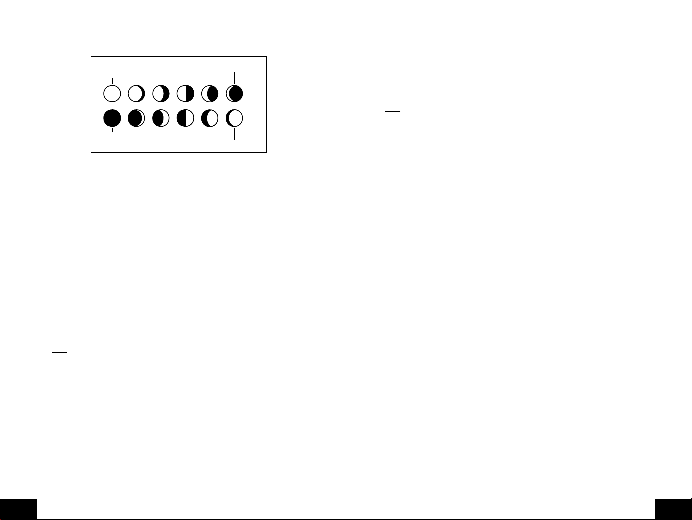
B. Fase Lunar
1. Hay 12 Fases Lunares mostradas en la Estación del Tiempo Interior; Así, cuando el icono
de la luna es todo el negro, es una luna llena. La estación de tiempo interior se programa
con todas las fases de luna del año 2000 hasta las 2099.
Fase entre media Luna y luna
Cuarto Cresciente
Luna Nueva
Luna Llena
Cuarto Menguante
llena en el periodo de la Luna Cresciente
Primer Cuarto
Ultimo Cuarto
Fase entre media Luna y luna
llena en el periodo del Menguante
2. La fase de la luna para cualquier fecha puede ser encontrada seleccionando una fecha
diferente mediante la sección programación de Salida/Puesta de Sol y Salida/Puesta de
Luna (sección A en Características y Operación).
C. Mínimo y máximo de Temperatura y Humedad
1. Mínimo y máximo de Temperatura y Humedad Interior
La Estación del Tiempo Interior automáticamente almacena el mínimo y máximo de
temperatura y humedad interior. Los valores de mínimo y máximo son actualizados
automáticamente cuando un nuevo mínimo o máximo es registrado, o hasta que
manualmente se reinicialice.
a. En el modo de visualización normal, Presione y suelte la "
IN
" tecla una vez para ver el
mínimo de temperatura y humedad interior ("MIN" será visualizado cerca de la
temperatura y humedad interior).
b. Presione y suelte la tecla "
IN
" otra vez para ver el máximo de temperatura y humedad
interior.
c. Presione y suelte la tecla "
IN
" otra vez para volver al modo normal (la interrupción
automática de los valores mínimo/máximo ocurrirá si ninguna teclas es presionada
por quince segundos).
Nota
: Para reinicializar los valores mínimo y máximo de temperatura y humedad interior,
Presione y sostenga la tecla "
IN
" por al menos dos segundos.
2. Mínimo y máximo Temperatura y Humedad Al Aire Libre
La Estación del Tiempo Interior automáticamente almacena el mínimo y máximo de
temperatura y humedad Al Aire Libre. Los valores de mínimo y máximo son actualizados
automáticamente cuando un nuevo mínimo o máximo es registrado, o hasta que
manualmente se reinicialice.
a. Los valores mínimo y máximo de temperatura Al Aire Libre (remoto) serán visualizados
debajo de la visualización de la temperatura Al Aire Libre.
b. Estos valores serán redondeados hacia abajo el mínimo y redondeados hacia para el
máximo.
Note
: El modo de alarma de temperatura comparte la misma visualización. Cuando los
valores están alarma están visualizados, "
remota. Para cambiar y volver entre las visualizaciones, presione la tecla "
ALARM
" será visualizado arriba de la temperatura
OUT
c. Para reinicializar los mínimo y máximo de temperaturas Al Aire Libre Presione y
sostenga la tecla "CH" por al menos un segundo.
D. Múltiples Sensores de Temperatura Remota
Las unidades WS-8025SU pueden recibir señales de 3 sensores remotos diferentes. Estos
sensores remotos extras pueden comprarse a través del mismo distribuidor de esta unidad. A
TX4U monitoreará la temperatura y humedad, a TX3U monitoreará temperatur a y visualizará
la temperatura en su LCD y el TX3UP monitoreará la temperatura vía una sonda de medición
de temperatura de tierra o agua.
Note
: Cuando ponga en funcionamiento sensores remotos múltiples es insertar baterías
primero en todos los sensores remotos, y en sucesión numérica. Segundo instale las baterías
en la estación de tiempo interior. Problemas de transmisión ocurrirán si esto no se hace
correctamente y si el tiempo total para la puesta en marcha excede 6 minutos
1. Puesta en Funcionamiento de Múltiples Unidades
a. Es necesario quitar las baterías de todas las unidades actualmente en funcionamiento.
b. Quite la tapa de las baterías de todos los sensores remotos.
c. Ponga todos los sensores remotos en orden numérico secuencial.
d. En orden secuencial, instale baterías siguiendo los mismos procedimientos de
instalación de baterías vistos en la sección de Guía Detallada de Puesta en
funcionamiento de este manual.
e. Instale baterías en la Estación del Tiempo Interior.
f. Siga Guía Detallada de Puesta en funcionamiento programación e instrucciones de
funcionamiento.
2. Viendo y Operando con Sensores Remotos Múltiples
a. Para ver la temperatura de un sensor remoto diferente Presione y suelte la tecla
"
CHANNEL
". Un cambio desde el número uno "encajado" al próximo deberá ser
observado en el AL AIRE LIBRE LCD.
b. El mínimo y máximo de temperatura del sensor remoto adicional serán visualizados
debajo de la temperatura actual del sensor remoto en el AL AIRE LIBRE LCD.
c. Para reinicializar las lecturas de mínimo y máximo de temperatura Presione y sostenga
la tecla "
RESET
" por 5 segundos y los registros de todos los sensores remotos serán
reinicializados.
Cada sensor remoto tendrá sus propios valores mínimo y máximo almacenados, como
también sus propios ajustes de alarma para temperatura. Reinicializando los valores
mínimo y máximo Al Aire Libre reinicializarán todos los registros de los sensores remotos.
E. ALARMA DE TEMPERATURA REMOTA
1. Activando la Alarma
Desde el modo normal, Presione y suelte la tecla "OUT" para saltar entre la alarma de
temperatura y los valores mínimo/máximo. "
ALARM
" será visualizado arriba de la
visualización de la temperatura remota; esto también activará la alarma de temperatura.
2. Ajuste la alarma de temperatura
a. Presione y sostenga la tecla "
OUT
" por dos segundos.
b. La temperatura baja estará titilando (32˚F por defecto/ajuste de fábrica).
c. Presione y suelte la tecla "+" o "-"para ajustar la temperatura desde -22˚F s +157˚F
("- -" si está fuera de este rango). Cualquier valor alcanzado bajo este hará sonar la
alarma.
d. Presione y suelte la tecla "
SET
" para avanzar a la alarma de temperatura alta.
".
P.56
S
P.57
S
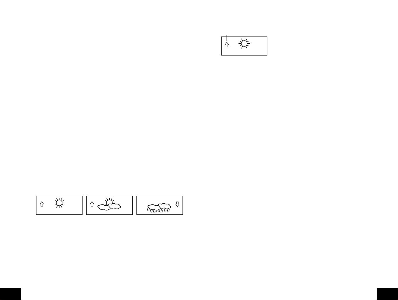
e. El ajuste de la temperatura alta está ahora titilando (86˚F por defecto/ajuste de fábrica).
f. Presione y suelte la tecla "+" o "-"para ajustar la temperatura desde -22˚F a +157˚F
("- -" si está fuera de este rango). Cualquier valor alcanzado arriba de este valor
sonará la alarma.
g. Presione y suelte la tecla "
visualización retornará automáticamente después de quince segundos y volverá al
modo normal automáticamente).
3. Cancelando la Alarma de Temperatura Mientras está Sonando
a. Mientras la alarma está sonando, presione cualquier tecla para enmudecer la alarma.
La temperatura titilará hasta que el anterior valor sea ajustado.
b. La alarmase reactivará automáticamente una vez el valor ha caído por debajo del
valor ajustado, o si un nuevo valor se ajusta.
F. Indicador de comodidad para la Temperatura y Humedad Interior
1. El indicador del nivel de comodidad aparece entre la temperatura interior y la humedad.
2. El indicador visualizará una "cara felíz" cuando la temperatura está entre 68˚F y 79˚F
(20˚C y 25.9˚C), y la humedad está entre 45% y 64%.
3. Una "cara triste" será visualizada cuando la temperatura y humedad están fuera de los
rangos mencionados.
4. Si la humedad está por debajo del 45% la palabra "DRY" aparecerá a la derecha del icono
de "cara triste".
5. Si la humedad está arriba de 54% la palabra "WET" aparecerá a la derecha del icono
"cara triste".
G. ICONO DE PRONOSTICO DEL TIEMPO E INDICADORES DE TENDENCIA DE PRESION
La característica del Pronóstico del Tiempo se estima ser exacta un 75%. El Pronóstico del
Tiempo está basado solamente en el cambio de la presión atmosférica en el tiempo. La WS8025SU promedia las lecturas pasadas de la presión atmosférica para proporcionar un
exacto, creando la necesidad de descartar todos los Pronóstico del Tiempo para las siguientes
12-24 horas después que la unidad ha sido puesta en funcionamiento, reinicializada, o movida
de una altitud a otra (por ej: desde un piso de un edificio a otro). En áreas donde el tiempo no
es afectado por el cambio de la presión atmosférica, esta característica será menos exacta.
1. Iconos del tiempo
a. Hay 3 posibles iconos de tiempo que se visualizarán varias veces en el centro de la
Estación del Tiempo Interior.
i
Soleado
ii
iiiNubes con lluvia- indica que se espera que el tiempo empeore (no que el tiempo va
b. Los Iconos del Tiempo cambian cuando la unidad detecta un cambio en la presión
atmosférica.
c. Los iconos cambian en orden, desde "soleado" a "parcialmente soleado" y a "nublado"
o al contrario.
d. No cambiarán desde "soleado" directamente a "lluvioso", Aunque es posible que el
cambio ocurra rápidamente.
e. Si los símbolos no cambian el tiempo no ha cambiado, o el cambio ha sido lento y
gradual.
P.58
S
- indica que se espera que el tiempo mejore (no que será Soleado).
Sol con Nubes
ser soleado con nubes)..
a ser lluvioso).
SET
" para volver al modo de visualización normal (o la
- indica que el tiempo esperado será parejo (no que el tiempo va a
pronóstico
f. La sensiblidad del cambio de ícono de pronóstico es ajustada por el usuario en la
sección F de la Guía Detallada de Puesta en Funcionamiento.
H. FLECHAS DE TENDENCIA DEL TIEMPO
Flecha de tendencia de Presión
1. Junto con el ícono de pronóstico también está una flecha de tendencia de presión.
2. Hay una que apunta hacia arriba (al lado izquierdo del LCD) y una que apunta hacia abajo
(al lado derecho del LCD).
3. Estas flechas reflejan los cambios actuales en la presión atmosférica.
4. Una flecha apuntando hacia arriba indica que la presión atmosférica está aumentando y
se espera que el tiempo mejore permanezca bueno.
5. Una flecha apuntando hacia abajo indica que la presión atmosférica está disminuyendo y
se espera que el tiempo se ponga peor o pemanezca malo.
6. Ninguna flecha indica que la presión está estable.
7. Una tormenta puede esperarse si hay una gota de 4 hPa o más en menos de 6 horas. El
ícono nubes con lluvia será visualizado y la flecha tendencia que apunta hacia abajo
estará titilando-indicando que la función de advertencia de tormenta ha sido activada. El
titilado se detendrá cuando la presión atmosférica se estabilice o empiece a aumentar.
I. ALARMA DE ADVERTENCIA DE TORMENTA
1. Una alarma puede ajustarse para advertir de una gota en la presión atmosférica.
2. Por favor siga las instrucciones de la programación de la sección F en la Guía Detallada
de Puesta en Funcionamiento para activar esta alarma
3. Cuando la presión atmosférica cae por el ajuste de nivel, una alarma sonará (si la alarma
está activada).
4. Para cancelar la alarma mientras está sonando presione cualquier tecla.
J. Tendencia de la Presión atmosférica para las Pasadas Dos Horas
La barra debajo de la tabla presión atmosférica histórica visualizará el cambio de la presión
atmosférica después de pasadas dos horas (valores basados en el cambio de hPa, 1 hPa
equivale a 0.03 inHg).
K. LECTURA DE LA PRESION ATMOSFERICA BAROMÉTRICA
1. La presión atmosférica barométrica actual será visualizada directamente debajo del ícono
de pronóstico del tiempo
2. La presión atmosférica relativa es calibrada por el usuario mediante el modo de
programación.
3. Por favor Siga las instrucciones de programación de la sección F en la Guía Detallada de
Puesta en Funcionamiento apar ajustar esta función.
4. Para saltar entre la presión atmosférica absoluta and relativa, presione the "-" tecla.
L. GRAFICO DE BARRA DE LA PRESION ATMOSFERICA HISTORICA
1. El gráfico de barras muestra en hPa (Hekto Pascal) la presión atmosférica grabada durante
las últimas 30 horas.
2. El eje de las abscisas muestra las horas en incrementos de -30 horas, -24 horas,
-18 horas, -12 horas, -6 horas, -3 horas, -1 horas, y 0 horas (actual).
3. El eje de ordenadas es ajustado en hPa: el “0” en este eje representa el actual hPa hPa,
y + o - 1,3,5, o 7 muestra (in hPa) que tan alta o baja fue la presión atmosférica pasada
comparada con la actual.
4. El “0” en el eje de ordenadas indica el valor de la presión atmosférica actual.
P.59
S
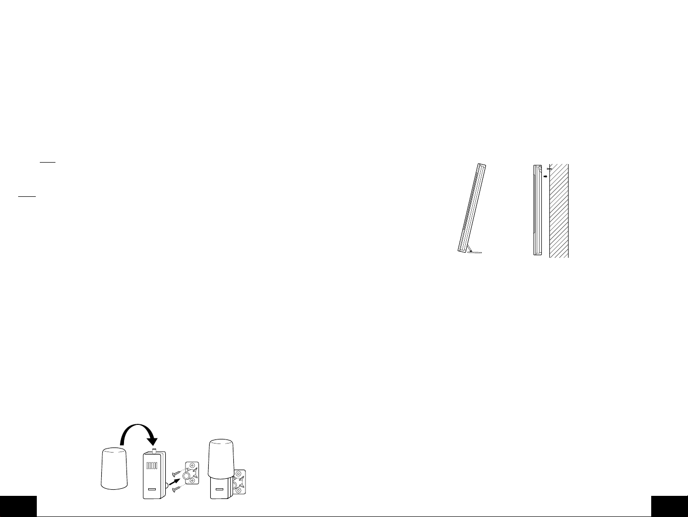
5. El “0h” en el eje de abscisas indica la hor a actual, así como también la presión atmosférica
actual.
6. Cada barra en el gráfico de barras representa un valor de 0.03 hPa, y cada barra también
tiene un valor correspondiente en el eje del vertical.
7. Las tendencias de la presión atmosférica pueden ser determinadas simplemente repasando
el gráficode barras.
a. Si las barras están subiendo (superior a la derecha que la izquierda) entonces la
presión atmosférica tiene una tendencia creciente, y el tiempo debe mejorar.
b. Si las barras están cayendo (más baja a la derecha que la izquierda) entonces la
presión atmosférica tiene una tendencia decayente, y el tiempo debe empeorar.
8. Multiplique los dos valor para encontrar presión atmosférica pasada (note el signo de los
valores + o-la en el eje vertical); por ej 0.03 hPa x 3 = 0.09 hPa, ahora agregue este valor
a la presión atmosférica (en LCD 4) para evaluar qué presiones atmosféricas pasadas
han sido.
9. El gráfico de barras constantemente se moverá para evitar quemar la pantalla LCD.
Note
: Esta función no puede ser apagada.
MONTAJE
Nota
: Antes de montar permanentemente asegúrese que La Estación del Tiempo Interior es capaz
de recibir la señal WWVB en la ubicación deseada. Para asegurar una lectura real de temperatura,
evite colocar el sensor hygro-térmico remoto (o cualquier sensor) donde la luz directa del sol pueda
alcanzar al sensor remoto. Recomendamos que usted ubique el sensor remoto en una pared orientada
al Norte o bajo una saliente. El rango de transmisión del sensor hygro-térmico remoto es de 200
pies. Sin embargo, obstáculos como paredes, concreto, y g r andes objetos metálicos pueden reducir
el rango. Coloque todas las unidades en su localización deseada y espere aproximadamente 15
minutos antes de montar permanentemente para asegurarse que allí es adecuada la recepción. Si la
Estación del Tiempo Interior pierde la señal del sensor remoto, visualizará la última lectura de
temperatura por 15 minutos. Después de 15 minutos de no recibir cualquier señal, la temperatura
remota visualizará "- -.-".
A. Montaje del Sensor hygro-térmico remoto
El sensor hygro-térmico remoto puede ser montado usando tornillos o usando cinta adhesiva.
1. Montaje con tornillos
a. Saque el soporte/receptor de Montaje del paquete.
b. Coloque el soporte de montaje sobre la superficie de montaje deseada.
c. A través de los 2 agujeros para tornillos del soporte marque la superficie de montaje
con un lápiz.
d. Donde haya marcado, inicie los agujeros usando los tornillos suministrados.
e. Quite los tornillos de la superficie de montaje.
f. Alinee el soporte de montaje con los agujeros iniciados.
g. Atornille el soporte de montaje en la superficie de montaje. Los tornillos deberán quedar
a ras con el soporte.
h. Ajuste el poste de montaje (en la parte de atrás del transmisor remoto) en el receptor
del soporte de montaje.
2. Montaje Con Cinta Adhesiva
a. Con una solución no abrasiva, limpie y seque la parte posterior del soporte de montaje
y la superficie de montaje para asegurar un sostenimiento seguro. La superficie de
montaje debe ser lisa y plana.
b. Quite la tira de protección de un lado de la cinta.
c. Presione firmemente en el área deseada en la parte de atrás del soporte de montaje.
d. Quite la tira de protección del otro lado de la cinta, y sitúe el soporte de montaje.
e. Presione firmemente el soporte de montaje en la superficie de montaje.
f. Ajuste el poste de montaje en el receptor del soporte de montaje.
B. Montaje del Centro del Tiempo WS-8025U
La Estación del Tiempo Interior puede ser montada de dos formas; libre de soporte o colgada
en una pared.
Para tener la Estación del Tiempo Interior libre de soporte, simplemente despliegue el soporte
de la parte de atrás y ponga en una superficie llana estable.
Para montar en la pared la Estación del Tiempo Interior;
1. Asegúrese que el soporte integrado está plegado.
2. Fije un tornillo (no incluido) en la pared deseada, dejando aproximadamente 3/16 de pulg.
(5mm) extendido fuera de la pared.
3. Coloque la Estación del Tiempo Interior en el tornillo usando el agujero de montaje de la
parte posterior. Suav emente hale hacia abajo la Estación del Tiempo Interior para asegurarla
en el tornillo.
CUIDADO Y MANTENIMIENTO
A. Deben evitarse temperaturas extremas, vibraciones, y golpes para prevenir daño a las unidades.
B. Limpie las pantallas y las unidades con un paño húmedo suave. No use que solventes o agentes
frotantes porque ellos pueden rayar y dañar las pantallas y cubiertas. No sumerja en agua.
C. Quite Inmediatamente todas las baterías bajas para evitar goteo y daño. Sólo reemplace con
baterías nuevas y del tamaño recomendado.
D. Abriendo las cubiertas invalida la garantía. No intente reparar las unidades. Avise a La Crosse
Technology para las reparaciones.
REMOTE
THERMO-SENSOR
433 MHz
P.60
S
REMOTE
THERMO-SENSOR
433 MHz
P.61
S

SOLUCION DE PROBLEMAS
Problema : El LCD es débil.
Solución : 1) Ponga el contraste del LCD en un nivel superior.
2) Reemplace baterías.
Problema : Ningún temperatura/humedad al aire libre se despliega.
Solución : 1) Quite todas las baterías, reinserte primero las del transmisor y después las del
Centro del Tiempo.
2) Coloque el sensor remoto más cerca de la pantalla.
3) Verifique seguro que todas las baterías son nuevas.
4) No se deben estar usando fuentes de interferencia en su proximidad (como monitores
de computadora, televisores, auriculares, o altavoces). La señal viaja en línea recta,
una fuente eléctrica cerca de esa "línea" puede causar interferencia.
Problema : Temperatura, humedad, o la presión atmosférica es incorrecta.
Solución : 1) Verifique/Reemplace las baterías.
2) Si hay transmisores múltiples en uso, chequee la localización del correspondiente a
cada uno.
3) Aleje el montaje de las fuentes de calor/frío.
4) Ajuste presión atmosférica relativa a un valor de una fuente fiable (reporte de radio o
de televisión, etc.).
5) El Centro del Tiempo y los transmisores se calibran en la fábrica. Si ha y un prob lema
constante, por favor llame a La Crosse Technology.
Problema : Despliega "- -" en humedad.
Solución : 1) La humedad está debajo de 1% o arriba del 99%.
2) Se usan TX3U o TX3UP para temperaturas remotas.
Problema : La hora WWVB y la fecha no se actualizan
Solución : 1) Espere toda una noche para que la señal sea recibida
2) Mueva el Centro del Tiempo lejos de fuentes de electricidad
3) Coloque el Centro del Tiempo cerca de una ventana orientada a Colorado
4) La primera recepción es más difícil, porque el Centro del Tiempo necesita cinco
minutos continuos de recepción de señal clara. Después de la recepción inicial de
hora/fecha, el Centro del Tiempo sólo requiere un minuto contin uo de recepción clara
cada noche.
Rango de la humedad relativa
Interior / Al aire libre: 1% a 99% con 1% de resolución. Despliega "--. -"
si está fuera de este rango.
Presión atmosférica
HPa/inHg absoluto: 700 hPa a 1099 hPa.
(20.67 inHg a 32.46 inHg).
HPa relativo (ajustable): 960 hPa a 1040 hPa.
InHg relativo (ajustable): 28.60 inHg a 30.45 inHg.
Ajuste de Sensibilidad hPa: 1 hPa a 4 hPa.
Presión atmosférica Histórica: Durante las últimas 30 horas (0, -1, -2, -3, -6, -12,
-18, -24 y–30 horas).
Intervalos de verificación de Datos
Temperatura interior: Cada 15 segundos.
Humedad interior: Cada 20 segundos.
Temperatura al aire libre: Cada 5 minutos.
Humedad al aire libre: Cada 5 minutos.
Actualización de lectura del Transmisor (dentro del sensor)
Temperatura al aire libre: Cada minuto.
Humedad al aire libre: Cada minuto.
Frecuencia de la transmisión: 433.92 MHz.
Extensión de transmisión: 200 pies (60m) en espacios abiertos
Fuente de Alimentación
Centro del Tiempo: 3 baterías AA (IEC LR6) 1.5V.
Transmisor Hygro -térmico: 2 baterías AA (IEC LR6) 1.5V.
INFORMACION DE LA GARANTIA
La Crosse Technology, Ltd. le otorga para este producto una garantía limitada por 1 año contra
daños de fabricación y los materiales.
Esta garantía limitada comienza a partir del día de la compra, solamente es valida para productos
comprados en América del Norte y solamente comprados al distribuidor original autorizado de este
producto. Para recibir servicio de la garantía, el comprador deberá contactar a La Crosse Technology,
Ltd para la evaluación de problemas y los tramites de servicio. Los servicios de la garantía deberán
ser hechos por el centro autorizado de servicio al cliente de La Crosse Technology, Ltd. El recibo
original de compra deberá ser incluido si este solicitado como prueba de la compra por La Crosse
Technology, Ltd o el centro de servicio autorizado de La Crosse Technology.
ESPECIFICACIONES
Señal de hora radio-controlada WWVB, 60 kHz desde Ft. Collins, CO,
Temperatura de funcionamiento
recomendada para Centro del Tiempo: 32˚F a 122˚F (0˚C a 50˚C).
Contraste LCD: 8 niveles (1-8).
Salida/Puesta de Sol, Salida/Puesta de Luna,
y fechas de las fases de la luna disponibles: De Enero 1 del 2000 hasta el 31 de diciembre del
Rango de medición de Temperatura
Interior: 14˚F a 140˚F con 0.2˚F resolución.
Al aire libre: -21.8˚F a 157.8˚F con 0.2˚F resolución.
P.62
S
2099
(-9.9˚C a 59.9˚C con 0.1˚C resolución).
"OFL" se despliega si está fuera de este rango).
(-29.9˚C a 69.9˚C con 0.1˚C resolución ) "OFL" se
despliega si está fuera de este rango).
La Crosse Technology, Ltd le reparará o le remplazará este producto, bajo nuestra discreción y se
hará gratuitamente tal como esta estipulado en la presente, con piezas o productos nuev os o reparados
si se encuentran que estos son defectuosas durante el periodo cubierto por la garantía limitada
especificado anteriormente. Todas las piezas y productos cambiados pasarán a ser propiedad de La
Crosse Technology, Ltd y deberán ser de vueltas a La Crosse Technology, Ltd. Las piezas o productos
cambiados seguirán cubiertos por la garantía original restante del producto, o noventa (90) días,
será lo que tenga mayor duración. La Crosse Technology, Ltd pagará los gastos de mano de obra y
materiales de todas las reparaciones cubiertas por esta garantía. Si hay alguna reparación necesaria
que no este cubierta por esta garantía o si el producto es examinado y no necesita ninguna reparación
el costo de la reparación o inspección del aparato le será cobrado al cliente. El propietario deberá
pagar los costos de envío para enviar su producto de La Crosse Technology, Ltd hasta un centro de
servicio autorizado de La Crosse Technology, Ltd. La Crosse Technology, Ltd le pagará los costos
razonables de envío de retorno al propietario del producto.
Su garantía de La Crosse Technology, Ltd cubre todos los defectos del material y fabricación del
producto con las siguientes excepciones: (1) los daños causados por accidentes, uso irrazonable o
negligencia (incluyendo la falta de mantenimiento razonable y necesario); (2) daños ocurrido durante
el envío/transporte (los reclamos deberán ser hechos al transportador); (3) daños o deterioro de
P.63
S

cualquier accesorio o superficie decorativa; (4) daños como resultado del no cumplimiento de las
instrucciones contenidas en el manual de instrucciones del usuario; (5) daños ocasionados por la
reparación o modificación efectuadas por personal distinto al del centro de servicio autorizado de La
Crosse Technology,; (6) unidades utilizadas para un uso diferente al del uso domestico (7) las
aplicaciones y usos para los cuales no esta destinado este producto o (8) la incapacidad del producto
de recibir la señal debido a cualquier fuente de interferencia. Esta garantía cubre solamente los
defectos actuales del producto mismo y no cubre los costos de instalación o desinstalación de una
instalación fija, la configuración normal, los reclamos basados en malas interpretaciones del vendedor
o las variaciones de funcionamiento resultantes de las circunstancias relativas con la instalación.
LA CROSSE TECHNOLOGY, LTD NO ASUMIRA NINGUNA RESPONSABILIDAD POR DAÑOS
INCIDENTALES, CONSECUTIVOS , PUNITIVOS U OTROS DAÑOS SIMILARES RELACIONADOS
CON LA UTILIZACION O EL MAL FUNCIONAMIENTO DE ESTE PR ODUCTO. ESTE PRODUCTO
NO DEBERA SER USADO PARA FINES MÉDICOS O PARA INFORMACION AL PÚBLICO. ESTE
PRODUCTO NO ES UN JUGUETE. MANTÉNGALO FUERA DEL ALCANCE DE LOS NIÑOS.
Esta garantía le confiere derechos legales específicos. Usted también puede tener otros derechos
específicos de su Estado. Algunos Estados no permiten la exclusión de daños y perjuicios
consecuenciales o incidentales, por lo tanto la anterior exclusión de limitación puede que no aplique
en su caso.
Para trabajos de la garantía, asistencia técnica o información, por favor contacte:
La Crosse Technology, Ltd
190 Main Street
La Crescent, MN 55947
Teléfono: 507.895.7095
Fax: 507.895.2820
support@lacrossetechnology.com
sales@lacrossetechnology.com
(información de otros productos)
www.lacrossetechnology.com
e-mail:
(trabajo de la garantía)
web:
Si tiene preguntas? Por favor vea el vídeo de instrucciones en
T odos los derechos reservados. Este manual no deberá ser reproducido de ninguna f orma, ni siquiera
en citas bibliográficas ni ser copiado o procesado electrónicamente, mecánicamente o químicamente
sin permiso escrito del editor.
Este manual puede contener errores técnicos y errores de impresión. La información contenida en
este manual se verifica regularmente y las correcciones se harán en la próxima edición. Nosotros no
aceptamos ninguna responsabilidad por los errores técnicos o los errores de impresión o sus
consecuencias.
Todas las marcas comerciales y las patentes están reconocidas
P.64
S
www.lacrossetechnology.info/8025
EJIN8025L221
P.65
S
 Loading...