


La Crosse Technology TX4U, TX5U, WS-7095U User Manual
WS-7095U
Wireless 433 MHz
24” Wall Hanging Wireless Weather Center
Instruction Manual
,1
P
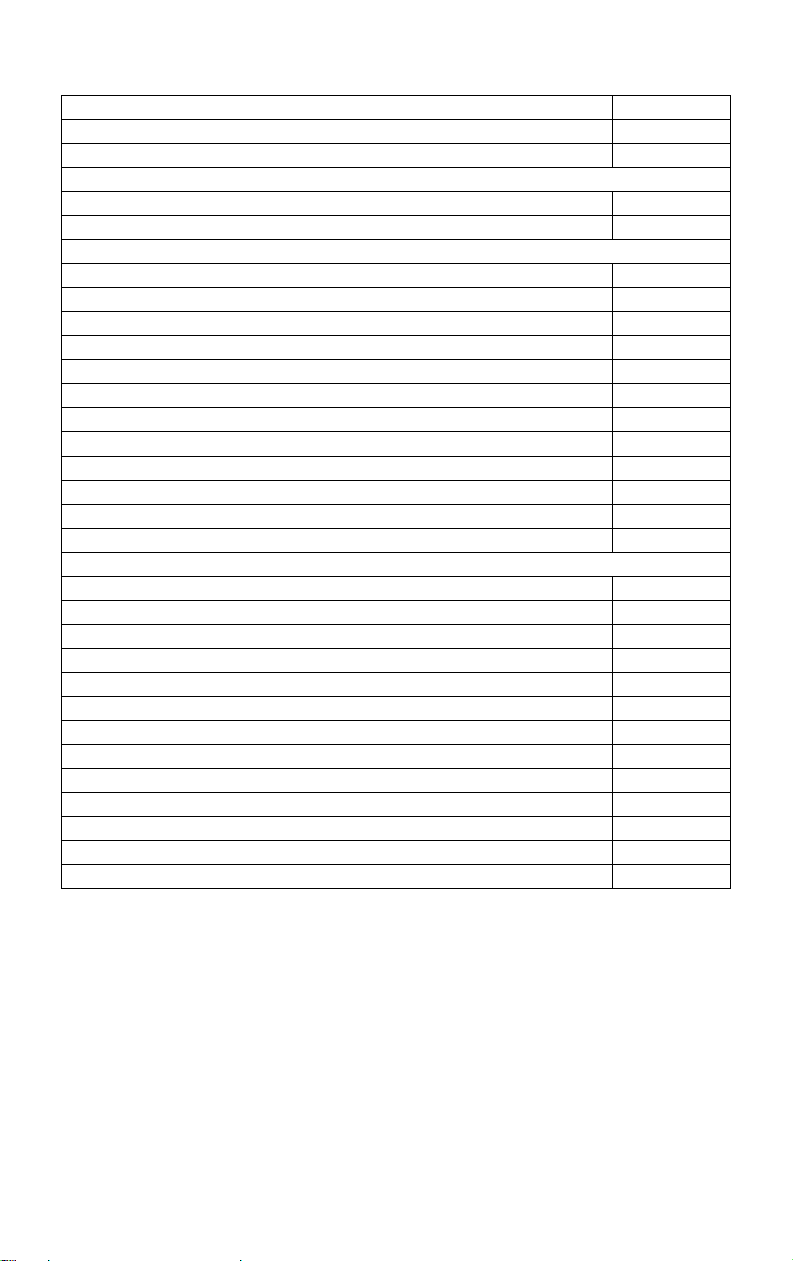
TABLE OF CONTENTS
Topic Page
Inventory of Contents/Additional Equipment: 3
Quick Set-Up Guide: 3
Detailed Set-Up Guide
Battery Installation: 4
LCD Screens: 5
Program Mode
Function Buttons: 6
LCD Contrast: 6
12/24-hour Time Display: 6
Time Setting: 6-7
Time Zone Setting: 7
Date Setting: 7
Date Display: 7
Selecting °F or °C and Inches or Millimeters:
7-8
Setting Forecast Sensitivity: 8
Displaying Relative/Absolute hPa/inHg: 8-9
Manually Setting Relative Air Pressure: 9
Setting Bar Graph Display: 9
Features & Operations
Moon Phase: 10-11
Minimum & Maximum Records (Indoor, Outdoor, Resetting): 11-12
Weather Forecast and Weather Icons: 12-14
Bar Graph Histories (Air Pressure and Rainfall): 14-16
Rainfall (Quantity & Resetting): 16-17
Manual setting of Rain Multiplicator: 17
Hard Reset of EEPROM Weather Center Memory: 17-18
Adding Sensors: 18-19
Mounting: 19-22
Maintenance and Care: 23
Troubleshooting: 23
Specifications: 24-25
Warranty Information: 26
2
INVENTORY OF CONTENTS
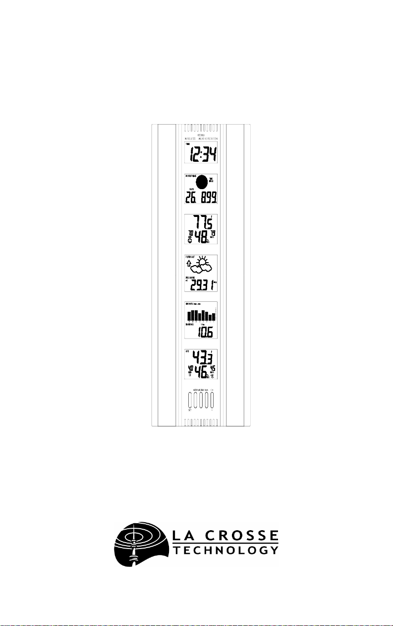
1. WS-7095U—24” Wall Hanging
Wireless Weather Center
(Figure 1).
2. TX4U—Remote Thermo-Hygro
(temperature-humidity) Sensor: includes a
mounting bracket/receptor, rain cover, two mounting screws, and
adhesive tape (Figure 2).
3. TX5U—Rainfall Sensor: includes a
base, rainfall collector, and two
mounting screws (Figure 3).
4. Instruction manual and warranty card.
ADDITIONAL EQUIPMENT (not included)
1. Three fresh 1.5V C batteries.
2. Four fresh 1.5V AA batteries.
3. Philips screwdriver.
4. Flathead screwdriver.
5. Four wall-mounting screws.
QUICK SET-UP GUIDE
1. Insert two AA batteries into the Remote Thermo-Hygro Sensor.
2. Insert two AA batteries into the Rainfall Sensor.
3. Insert three C batteries into the Weather Center.
4. Wait 12 minutes, or until the Weather Center has received signals
from the Remote Thermo-Hygro, and Rainfall Sensors.
5. Set time and date.
6. Mount the units, ensuring they are sending and receiving signals.
,1
P
3
DETAILED SET-UP GUIDE
I. BATTERY INSTALLATION
Batteries will fit tightly. To avoid start-up problems, make sure that the
batteries do not spring free.
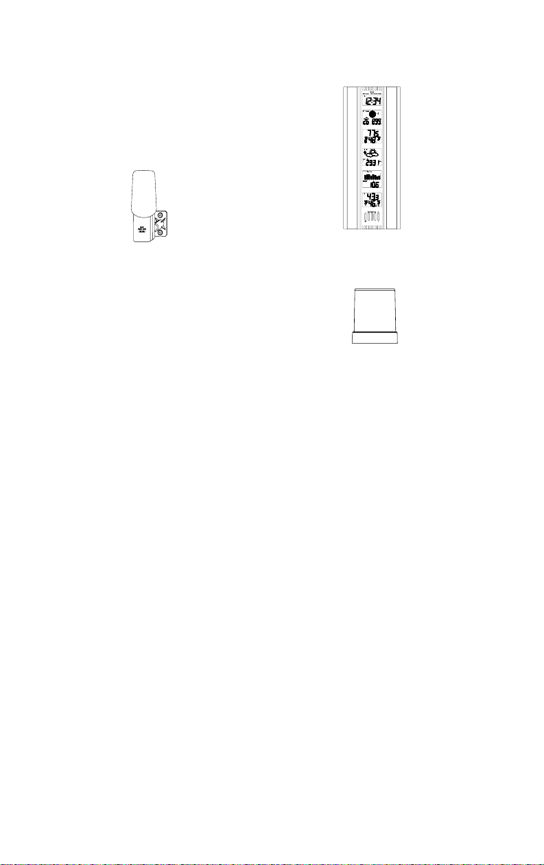
A. REMOTE THERMO-HYGRO SENSOR
Mounting
Bracket/Receptor
Rain
Cover
Thermo-Hygro
Sensor
1. Pull the cylindrical rain cover off the sensor.
2. Remove the battery cover (located on the backside of the sensor,
above the mounting post and bracket). Press the arrow and slide
the battery cover off.
3. Observing the correct polarity install 2 AA batteries.
4. Replace battery cover, and place rain cover snugly onto the sensor.
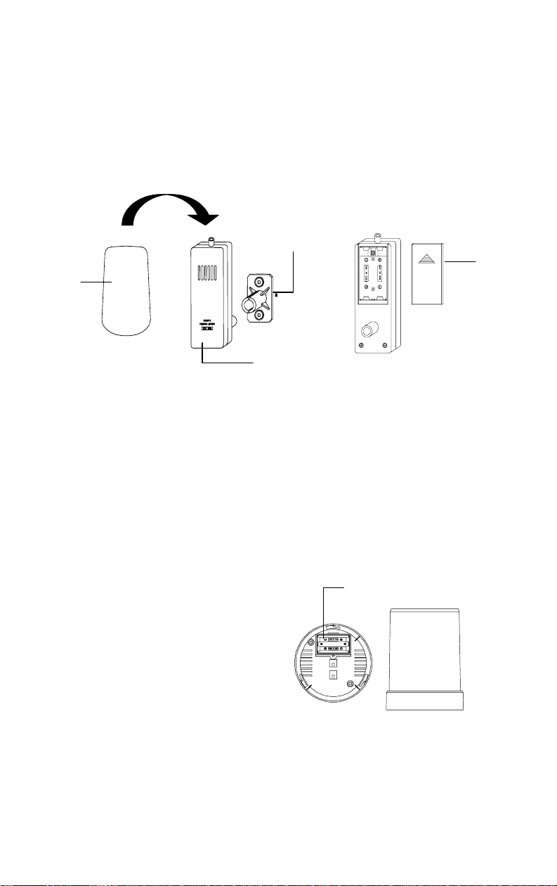
B. RAINFALL SENSOR
1. Remove the flat-head screw and battery cover, located on the
underside of the base.
2. Observe the correct
polarity, and install two
Battery
Compartment
AA batteries.
3. Make sure the rubber
weather seal is in place and
replace the battery cover
and screw.
Battery
Cover
4

C. WEATHER CENTER
1. Remove the battery cover. To
do this, place a solid object in
the space provided at the lowercentral position of the battery
cover (the cover has white
writing on it) then push up and
pull out on the battery cover.
2. Observe the correct polarity, and
Battery
Cover
install three C batteries.
3. Replace the battery cover.
Battery
Compartment
THE LCD SCREENS
Immediately after the batteries have been installed, the LCD (Liquid Crystal
Display) Screens will completely light up for a brief moment. There are 6 LCD
Screens, each displaying different information.
Note:
After the LCD Screens briefly light up, “267” will appear in the LCD 1,
then the LCD’s will display the default settings. A low-battery warning-icon
appears in LCD 1 beside the “TIME” icon (this should not be on). There is also
a satellite icon that appears in LCD 6, under the “MAX” icon—this icon
informs the user that the Weather Center is receiving signals from the sensors.
Within 12 minutes the Outdoor temperature and humidity should be displayed—
if not, remove batteries from all units and repeat battery installation.
Following is a general display
description of each LCD. Details
concerning the LCD Screens will be
LCD 1
explained during the complete
Programming sections and the Features
& Operations sections.
,1
LCD 2
LCD 1—shows the time.
LCD 2—moon phases and dates.
LCD 3—indoor temperature/humidity.
LCD 4—forecast icons and air pressure.
LCD 5—rainfall/air pressure histories,
and rain quantity.
P
LCD 3
LCD 4
LCD 6—outdoor temperature/humidity.
LCD 5
LCD 6
5

PROGRAM MODE
The Program Mode is laid out in a manner that allows you to program each
function separately, or you can follow the instructions entirely to program
the Weather Center. Complete programming is usually done for the initial
set-up, and will require you to skip step 1 of each programming section
(from section III to XII). The programming mode can be exited at any time
by either pressing the MIN/MAX button, or waiting for the 20-second timeout to take effect.
**Important note: Due to a programming error, the WS-7095U will not
properly recognize the dates March 1 or 2. When the date switches from
February 28 (February 29 in leap years), the unit will reset all information to
the default values. Any attempt to set this unit to March 1 or 2 will give the same
result. To prevent this, set the unit to March 3 on February 28 o r sooner. Once
the actual date is March 3, you may then reset it. As of this prin ting , no softwar e
changes are scheduled, and we apologize for that. This product is very
specialized, and volumes do not allow us to easily change the software. We
appreciate your business, and strive to maintain our quality of products. We
hope that you will find this unit has enough good features to help you overloo k
the missed programming. Feel free to call or e-mail us with any further
questions.
I. FUNCTION BUTTONS
There are 5 function buttons located on the front of the Weather Center,
under the LCD Screens. The function buttons are labeled: SET, MOON,
MIN/MAX, RAIN, and CH/+.
II. SETTING THE LCD CONTRAST
1. Hold down the SET button for 3 seconds, the default setting
“LCD 7” will flash in LCD 2.
2. Press the CH/+ button to advance through the LCD settings.
There are 16 settings to select from—“LCD 0” is the lightest and
“LCD 15” is the darkest.
3. Press the SET button to confirm, and to advance to select
12/24-hour time display.
III. 12/24 HOUR TIME DISPLAY SELECTION
1. Press the SET button twice to enter the 12/24-hour selection mode.
2. The default setting “12” will flash in LCD 1.
3. Use the CH/+ to select either “12” or “24” hour time display.
6

4. Press the SET button to confirm, and to advance to the Time
setting mode.
IV. TIME SETTING
Note:
The default time, after battery installation is “12:00.” The
Weather Center will begin to keep track of time after this.
1. Press the SET button three times to enter the Time setting mode.
2. The hour digit will flash in LCD 1.
3. Press the CH/+ button to advance the hours.
Note:
When setting the hours notice that there is no “AM” icon to
indicate that the time being set is in the AM. There is only a “PM”
icon. Be sure to set the time accordingly.
4. Press the SET button to confirm, and advance to set the minutes.
5. The minute digit will flash in LCD 1. Press the CH/+ to advance
the minutes (holding the CH/+ down will advance the minutes in
increments of five).
6. Press the SET button to confirm, and to advance to the Time Zone
setting.
V. TIME ZONE SETTING
This is a feature available on the WS-7095U, it is designed for use in
Germany. You may ignore this feature.
1. Press the SET button five times to enter this setting mode.
2. “Zo 0” will flash in LCD 1.
3. Press the SET button again to advance to set the date.
VI. DATE SETTING
1. Press the SET button six times to enter the Date Setting mode.
2. The default year “98” will flash in LCD 2.
3. Press the CH/+ to change the year.
4. Press the SET button to confirm the year, and to advance to set the
month. The default month digit “1” will flash in LCD 1.
5. Press the CH/+ to change the month.
6. Press the SET button to confirm, and to advance to set the date.
The default date digit “1” will flash in LCD 1.
7. Press the CH/+ to change the date.
8. Press the SET
button to confirm, and to advance set the Date
Display.
7

VII. DATE DISPLAY SETTING
1. Press the SET button nine times to enter the Date Display setting
mode.
2. The default “month/date/year” display will flash in LCD 2.
3. Press the CH/+ button to toggle between the default setting and the
“weekday/month/day” setting.
4. Press the SET button to confirm, and to advance to select °F or °C.
VIII. SELECTING °F OR °C AND INCHES OR MILLIMETERS
1. Press the SET button ten times to enter the °F/°C setting mode.
2. The default “F” will flash in LCD 1.
3. Press the CH/+ button to toggle between “F” and “°C.”
Note:
When °F is selected, the rainfall measurement will change to
inches. When
to millimeters. When the selection is made the effects are seen
immediately in temperature and rainfall measurement reading s
found in other LCD screens.
4. Press the SET button to confirm, and to advance to set the Weather
Forecast Sensitivity.
IX. WEATHER FORECAST SENSITIVITY SETTING
Note:
A higher hPa (Hekto Pascal) setting decreases the forecasting
sensitivity of the unit, this feature is available for persons living in areas
where air pressure changes are significant. (not necessarily related to a
change of weather). A lower hPa setting is available for areas with a
more constant air pressure. This designates that it takes 2 hP a of
pressure change to change the forecast icon. Note that 1 hPa change =
0.03 inHg (Inch Column of Mercury) change. 1 hPa= 1 mb (millibar).
The hPa options that appear in LCD 4 are “2” hPa= 0.06 i nH g, “3”
hPa= 0.09 inHg, and “4” hPa= 0.12 inHg.
1. Press the SET button eleven times to reach the Weather Forecast
Sensitivity setting mode.
2. The default sensitivity level of “3” will flash in LCD 4.
3. Press the CH/+ button to select a weather forecast sensitivity level
(2 through 4).
4. Press the SET button to confirm, and to advance to the Relative or
Absolute display setting.
°
C is selected, the rainfall measurement will change
8

X. DISPLAYING RELATIVE hPa/inHg OR ABSOLUTE hPa/inHg
Note: Air pressure can be displayed in four different measures:
Relative hPa/inHg and Absolute hPa/inHg. Absolute settings give a true
and real-time air pressure reading (at user’s location) that cannot be
manually calibrated. Relative air pressure is measured in relation to sea
level and is the standard meteorological form of measure. Relative air
pressure settings must be manually programmed to suit the users needs.
Relative air pressure can be found from local weather services. Absolute
air pressure decreases by about 0.01 inHg for every 10 feet in altitude.
In higher altitudes (above 6,500 feet), this effect is less noticeable. The
WS-7095U will measure absolute pressure reliably up to 7,500 feet.
There is no limit for relative air pressure since the user sets it.
1. Press the SET button twelve times to reach Relative or Absolute
Display setting mode.
2. The default “rel 29.91 inHg” will flash in LCD 4. Press the CH/+
button to toggle through “abs --.-- inHg”, “rel 1012.55 hPa”,
“abs --.-- hPa”.
3. Press the SET button to confirm, and to advance to the next setting
mode. The next setting mode depends on which was chosen,
Absolute or Relative. If Absolute is displayed, the next setting
mode will be to set the Bar Graph Display. If Relative is
displayed, the next setting mode will be to Manually set the
Relative Air Pressure.
9
 Loading...