


Touch Screen Weather Center Model WS-3610
QUICK SET UP GUIDE
1 Shipping Contents
The shipping contents of the WS-3610 Touch Screen Weather Center include a Base
Station (Receiver), a Thermo-Hygro Sensor (433 MHz Transmitter), a Rain Sensor
and a Wind Sensor, the respective Connecting Cables, an AC Adapter and a CDROM with a Package of PC Software for collected Weather Data.
2 Connections
Connect the Rain Sensor and Wind sensor cables to their respectively marked jacks
in the Thermo-Hygro sensor BEFORE powering up the Base Station or the Thermo-
Hygro Sensor.
The Thermo-Hygro Sensor and Base Station can be directly connected via cable if
the wireless 433 MHz radio transmission is not desired, and data transmission free of
localized radio interference is an important factor.
(The use of the direct cable connection between the Base Station and Thermo-Hygro
Sensor depends on the finally chosen operating mode (see Item 3 Power Supply).
3 Power Supply
Depending on the type of data transmission from transmitter to receiver the Base
Station and Thermo-Hygro Sensor can be supplied with power in the following
possible combinations:
• With cable connection or 433 MHz radio transmission: Base Station uses batteries, Thermo-Hygro Sensor uses batteries.
• With 433 MHz radio transmission: Base Station uses AC/DC adapter, ThermoHygro Sensor batteries.
• With cable connection: Base Station and Thermo-Hygro Sensor use the AC/DC
adapter.
The last mentioned cable connection eliminates the need for batteries (they may still
be used as backup if there is a power outage) and provides data transmission that is
less prone to interference.
4 To Begin Operation
To begin it is necessary to decide whether to use AC power (adapter included) or
batteries to operate the system. Either method will ensure a connection to the
Thermo-Hygro Sensor and Base Station by cable or by a 433 MHz wireless radio
signal.
Note: When first setting up the Weather Center, it is important to temporarily
set up the entire system in close proximity on a table or counter top as it is
intended to be used (wired or wireless). This step serves as a test to ensure
that all components function correctly prior to final installation.
In all cases the Thermo-Hygro sensor must be powered up prior to the Base Station
since the Sensor will send an identification code that must be received and stored by
the Base Station within the first few minutes of operation. It is also important to allow
the Base Station to operate for at least 15 minutes prior to touching any fields on the
display.

5 System Start
After inserting the batteries or connecting the AC adapter, the LCD will display all of
the digital segments for a few seconds.
Immediately after this the Base Station will enter a test mode during which all
measured and received weather data is cycled through, updated and displayed for a
period of approximately 15 minutes.
During this test mode, the unit will not receive the WWVB time signal.
Note: The test mode is designed so that you may check all of the cables for correct
connection and all of the components for proper function.
• To manually test the Wind Sensor: manually turn the wind-gauge, moving the
weather-vane
• To manually test the Rain Sensor: tilt the rain sensor back and forth in order to
hear the impact of the internally moving seesaw
• To manually test the Thermo-Hygro: with both the Base Station and Thermo-
Hygro placed next to each other, compare the INDOOR and OUTDOOR
sections of the LCD to make sure that they both produce the same data.
After completing the test mode, the Touch Screen Weather Center will automatically
switch to the normal display mode in order to perform all other settings. At this point
the Base Station will also automatically start searching for the WWVB time signal.
6 Placement
After the Weather Station has been checked for correct function with regard to the
above points and found fit, the mounting of the system components can take place. It
must be ensured however that all components work properly together at their chosen
mounting or standing locations. If there appear to be problems with the 433 MHz
radio transmission they can typically be overcome by moving the Thermo-Hygro
Sensor.
7 Setting Up
• All actions and functions of the Weather Center begin by slightly touching, not
pressing, the Touch Screen. The switchable areas appear with a star (٭) symbol
in the bottom section of the LCD. or above for the corresponding values.
• The following selections in the bottom section of the LCD are used to set any
function, value, or unit within any mode:
٭ON٭ or
٭OFF ٭ ,٭ UP٭ or ٭DOWN٭, or
by directly selecting the unit.
• When setting any function, value, or unit,
٭NEXT٭ will advance the screen to the
next menu option; ٭EXIT٭ will exit the menu and return to the normal display
mode.
• Every programming step activated by touching a switchable area on the screen is
acknowledged by an audible beep when the buzzer option is switched to “ON”.
• During any menu operation, if no active area is touched for 20 seconds, the menu
is automatically deactivated and the screen will return to the normal display mode.

8 PC Connection
In addition to the LCD monitor, the WS-3610 has the ability to transfer all collected
time and weather data to a PC via a Com port connection. The supplied PC software
provides complete sets of history data, data graphing, and webpage update
capabilities.
An included COM port cable provides the means to connect the Base Station to the
PC. The “Heavy Weather Pro 3610” software package (also included) must be
installed on the PC.
This software allows the display of all present weather data with graphic symbols. It
further allows the display, storage and printing of history data sets, whose volume
exceeds the maximum 1750 data sets of the Base Station, and is only limited by the
capacity of the PC’s main memory.
Furthermore the present weather data can be uploaded to web sites by means of the
“Web Publisher” software. History data can be displayed as diagrams and graphs
using the “Weather Review” software.
For further details on the PC Connection please see the Help File on the installation disk for the software.

TOUCH SCREEN WEATHER CENTER
MODEL WS-3610
Operation Manual
1

Table of Contents
1 ................... General
2 ................... Important Notes for Operating the Touch Screen
3 ................... To Begin Operation
3.1 ............. Wiring the System
3.2 ............. Power Supply
3.2.1........ Use Batteries for Power
3.2.2........ Use AC Adapter for Power
3.2.3........ Cable Connection
3.3 ............. System Start
3.4 ............. Placement
4 ................... Setting Up
5 ................... Display of stored Min/Max Values and Alarm Value
Settings
6 ................... Radio Controlled WWVB Signal Reception and Clock
7 ................... Weather Tendency
8 ................... Barometric Pressure History Bar Graph
9 ................... Operating and Setting of various Functions
9.1 ............. Air Pressure
10 ................. Operating and Setting the Rain Function
11 ................. Additional Information – Outdoor Temperature Display
12 ................. Additional Information – Wind Display
12.1 ........... Operating and Setting the Wind Direction Alarm
13 ................. Operating and Setting the Backlight, Buzzer and Alarm in
the WIND Section
13.1 ........... EL Backlight
13.2 ........... Buzzer
13.3 ........... Alarm
14 ................. PC Connection
14.1 ........... Data Storage
14.2 ........... Data Recall
14.3 ........... Connections and Software
15 ................. Technical Data
15.1 ........... Outdoor Data
15.2 ........... Data Transmission by 433 MHz Signal
15.3 ........... Data Transmission by Cable
15.4 ........... Indoor Data
15.5 ........... Power Supply
15.6 ........... PC Connection
15.7 ........... Dimensions
16…………….TX11U Rain Sensor
17…………….TX12U Wind Sensor
18…………….TX13U Thermo/Hygro Sensor
2

1 General
The shipping contents of the WS-3610 Touch Screen Weather
Center include a Base Station (Receiver), a Thermo-Hygro
Sensor (433 MHz Sensor), a Rain Sensor and a Wind Sensor,
the respective Connecting Cables, an AC Adapter and
a CD-ROM with a Package of PC Software for collected
Weather Data.
The Base Station is equipped with a Touch Screen LCD Monitor,
which features a variety of time and weather data via a
comprehensive and interactive menu. The following list
describes the features in order from top to bottom:
• Radio Controlled Time (Time)
• Perpetual Calendar (Date)
• Weather Forecast with Tendency Arrow (Tendency)
• Barometric Pressure and 72 Hour History Bar Graph
(Pressure, Pressure History)
• Indoor Temperature and Humidity (Indoor Temp, Humidity)
• Wind
• Rain (Rain)
• Outdoor Temperature and Humidity (Outdoor Temp,
Humidity)
Additional data can by displayed by certain touch screen field
combinations that are explained later.
Note: When the menu is touched and activated, the “active
menu steps” temporarily replace all of the “standard
indications” as mentioned in the list above.
In addition to the LCD monitor, the WS-3610 has the ability to
transfer all collected time and weather data to a PC via a Com
port connection. The supplied PC software provides complete
sets of history data, data graphing, and webpage update
capabilities.
3

2 Important Notes for Operating the Touch Screen
(Generally Applicable)
• All actions and functions of the Weather Center begin by
slightly touching, not pressing, the Touch Screen.
• The switchable areas appear with a star (٭) symbol in the
bottom section of the LCD or above the corresponding
values.
• The following selections in the bottom section of the LCD are
used to set any function, value, or unit within any mode:
٭ON٭ or ٭OFF ٭ ,٭ UP٭ or ٭DOWN٭, or by directly selecting
the unit.
• When setting any function, value, or unit, ٭NEXT٭ will
advance the screen to the next menu option; ٭EXIT٭ will exit
the menu and return to the normal display mode.
• Every programming step activated by touching a switchable
area on the screen is acknowledged by an audible beep
when the buzzer option is switched to “ON”.
• During any menu operation, if no active area is touched for
20 seconds, the menu is automatically deactivated and the
screen will return to the normal display mode.
3 To Begin Operation
To begin it is necessary to decide whether to use AC power
(adapter included) or batteries to operate the system. Either
method will ensure a connection to the Thermo-Hygro Sensor
and Base Station by cable or by a 433 MHz wireless radio signal.
Note: When first setting up the Weather Center, it is
important to temporarily set up the entire system in
close proximity on a table or counter top as you intend
to use the system (wired or wireless). This step serves
as a test to ensure that all components function
correctly prior to final installation.
4

3.1 Wiring the System
Connect the Rain Sensor and Wind sensor cables to their
respectively marked jacks in the Thermo-Hygro sensor BEFORE
powering up the Base Station or the Thermo-Hygro Sensor.
The Thermo-Hygro Sensor and Base Station can be
directly connected via cable if the wireless 433 MHz
radio transmission is not desired, and/or data
transmission free of localized radio interference is an
important factor.
3.2 Power Supply
Power can be supplied to the Weather Center using batteries or
the AC adapter. In the case that the AC adapter is used, it will
provide all required power to the system if the Base Station and
Thermo-Hygro Sensor are wired directly together.
3.2.1 Use Batteries for Power:
-
First insert two Type C alkaline 1.5 V batteries into the
battery compartment of the Thermo-Hygro-Sensor.
-
Immediately after, insert three Type AA alkaline 1.5 V
batteries into the battery compartment of the Touch Screen
Base Station.
3.2.2 Use AC Adapter for Power:
-
First insert two Type C alkaline 1.5 V batteries into the
battery compartment of the Thermo-Hygro-Sensor.
-
Immediately after, connect the AC adapter to the Base
Station, and then plug it into an AC outlet.
-
When the AC adapter is used, batteries may also be placed
in the Base Station to serve as a backup power supply if
there is a power outage.
Note: In either case, it is important to observe this order of
succession because the Sensor will send an identification
code that must be received and stored by the Base Station
within the first few minutes of operation.
5

It is also important to allow the Base Station to operate for
at least 15 minutes prior to touching any part of the Touch
Screen display.
Once these steps have been completed, the correct operation of
the entire weather system is ensured.
3.2.3 Cable Connection:
When operating a completely wired system, (cable connection
between Base Station and Thermo-Hygro, as well as a
connection between the individual sensors) power will be
supplied not only to the Base Station but to the all of the sensors
as well when the AC adapter is used.
Note: Operating the system directly wired while powering the
Base Station solely by batteries is not recommended due to the
considerably higher power consumption of the wired
configuration. The batteries may however remain in the Base
Station for emergency supply in case of a power failure.
A change from cable operation to 433 MHz radio
transmission or vice versa is possible in any case since
the Base Station will recognize this change and will
automatically switch to the appropriate operating mode.
3.3 System Start
After inserting the batteries or connecting the AC adapter, the
LCD will display all of the digital segments for a few seconds.
Immediately after this the Base Station will enter a test mode
during which all measured and received weather data is cycled
through, updated and displayed for a period of approximately 15
minutes.
During this test mode, the unit will not receive the WWVB time
signal.
6

Note: The test mode is designed so that you may check all of the
cables for correct connection and all of the components for
proper function.
• To manually test the Wind Sensor: manually turn the
wind-gauge, moving the weather-vane.
• To manually test the Rain Sensor: tilt the rain sensor
back and forth in order to hear the impact of the
internally moving seesaw.
• To manually test the Thermo-Hygro: with both the Base
Station and Thermo-Hygro placed next to each other,
compare the INDOOR and OUTDOOR sections of the
LCD to make sure that they both produce similar data
(within the specifications of the units).
After completing the test mode, the Touch Screen Weather
Center will automatically switch to the normal display mode in
order to perform all other settings. At this point the Base Station
will also automatically start searching for the WWVB time signal.
3.4 Placement
Once the Base Station and Sensors have been checked and
validated for correct function as mentioned in 3.3, all the system
components are ready to be permanently mounted.
It is critical to ensure that all components work properly together
at their chosen mounting or standing location. If it appears that
the Base Station is not receiving the wireless 433 MHz radio
transmission, moving the Thermo-Hygro Sensor to a different
location will usually fix the problem.
Note: The radio communication between receiver and sensor
can reach distances of up to 330 ft providing that there are
no interfering obstacles such as buildings, trees, vehicles,
high voltage lines, or similar obstructions.
If possible, PC monitors, radios, TV sets, and other
sources of radio interference should also be avoided.
7

4 Setting Up:
Note: Because of the default settings already determined by
the manufacturer, it may not be necessary to alter the
basic settings other than Relative Air Pressure (see
further down) If changes to the settings are needed, they
can easily be made if desired.
Touching the screen in the center of the text display within the
bottom two lines of the LCD will enter into the menu shown
below.
Touching the ٭SETUP٭ field will enter the setup mode.
The basic settings can now be performed in the following
successive order:
LCD Contrast
→ Contrast can be set in 8 steps from 0 to 7
(Default is 4).
Time Zone
→ Time Zones can be set in a range from
-12 to +12 hours.
Note: U.S.A. time zones will be displayed (not in hours) but in
the respective time zone abbreviations:
-4 h → ATL (Atlantic Time)
-5 h → EST (Eastern Standard Time)
-6 h → CST (Central Standard Time)
-7 h → MST (Mountain Standard Time)
-8 h → PST (Pacific Standard Time)
-9 h → ALA (Alaska Time)
-10 h → HAW (Hawaiian Time)
(Default is -5 h → EST (Eastern Standard Time).
8

Daylight Saving Time
(DST) → Daylight Saving time can be set
to on or off. The “ON” setting will automatically change the
WWVB Time Display from summer time to wintertime and vice
versa when it is activated. (Default is DST “ON”).
To proceed, touch ٭NEXT٭.
WWVB Radio Controlled Clock
(RCC) → ON/OFF. When the
“OFF” setting is selected, the clock is operates as a normal
Quartz clock (Default is RCC “ON”).
12/24 hour Time Display Format
When 12h format is selected, the hour is shown with « A.M »
between midnight and noon, and « PM » between noon
and midnight. (Default is 12-hour format).
Units
• Temperature (Temp) is displayed in °F or °C (Default is °F).
• Wind Speed (Wind) is displayed in mph, km/h, m/s, knots or
Beaufort (Default is mph).
• Rain Amount (Rain) is displayed in inch or mm
(Default is inch).
• Air Pressure (Press) is displayed in inHg or hPa
(Default is inHg).
9

Relative Air Pressure
(Rel. Pressure) → This should be set
locally to ensure a valid reference for air pressure in regards to
the local height above sea level (Default is 29.91 inHg).
Weather Tendency
(Tendency) → The Weather Tendency
sensitivity has 3 steps of sensitivity: 0.06 inHg, 0.09 inHg, and
0.12 inHg. (Default 0.09 inHg) In most cases the default works
well; however this should be set to 0.06 near the ocean and
0.012 in desert areas.
Storm Warning
(Storm) → Storm Warning sensitivity has 7 steps
of sensitivity: increments of 0.03 inHg from 0.09 inHg to 0.27
inHg, for storm warning display at a decrease of air pressure
over 6 hours (Default 0.18 inHg).
Activate or Deactivate storm warning alarm with ٭ON ٭ /٭ OFF٭
(Default is ON).
Relearn Mode
(Relearn Tx) → Allows the WS-3610 to relocate
the outdoor sensor (for example, after a changing a battery in the
Thermo-Hygro) without the necessity of a complete re-setup of
all system components → Acknowledge with ٭CONFIRM٭.
Default Settings
(Factory Reset) → Allows the reset of all
settings and/or stored values to the factory default →
Acknowledge with ٭CONFIRM٭.
10

Once all of the settings have been made, touch ٭EXIT٭ to leave
the basic setup mode.
5 Display of stored Min/Max Values
and Alarm Value Settings
Upon recall, named values will display and flash in their
respective sections.
Min/Max and alarm values are recalled from the menu shown
below which must be activated by touching the Touch Screen in
the center of the text display section (last two lines at the bottom
of the LCD). Touching the *MINMAX* or *ALARMS* field will
display the corresponding values.
The Min/Max values can also be recalled individually by touching
the respective area of the display. Example: Touching the
“Indoor” section of the display will activate the menu shown
below. Min, Max, and Alarm values can then be displayed by
touching the corresponding field.
Note: When individual Min/Max values are displayed; the top line
of the LCD screen will automatically display the time and
date that the data was recorded.
The following menu item will appear upon touching the
٭ALARMS٭ field. Low and high alarms are displayed via the
11

corresponding *LO AL* and *HI AL* fields; the individual values
are displayed in the same manner as individual Min/Max values.
(See above)
At any time the opposite respective menu (MIN/MAX or ALARM)
can be accessed via its corresponding field.
Touching the *EXIT* field at any time will return the LCD to its
normal display.
6 Radio Controlled WWVB Signal Reception and Clock
The NIST (National Institute of Standards and Technology—
Time and Frequency Division) WWVB radio station is located in
Ft. Collins, Colorado. A tower located there transmits the exact
time and date signal continuously throughout the United States
at 60 kHz. The signal can be received up to 2,000 miles away
through the internal antenna in the Base Station.
The WWVB radio station derives its signal from the NIST Atomic
clock in Boulder, Colorado. A team of atomic physicists is
continually measuring every second, of every day, to an
accuracy of ten billionths of a second per day. These physicists
have created an international standard, measuring a second as
9,192,631,770 vibrations of a Cesium-133 atom in a vacuum. For
more information on the atomic clock and WWVB please see the
NIST website at
http://www.boulder.nist.gov/timefreq/stations/wwvb.htm
.
12

Due to the nature of the earth’s ionosphere, WWVB signal
reception is very limited during daylight hours. The base station
will search for the signal every night when the reception is the
strongest.
The WWVB Radio Controlled Clock in the Base Station is
normally controlled by the radio signal of the WWVB time code
sensor and will thus set time and date automatically. Under bad
reception conditions however both time and date can be set
manually:
Setting the Time
To set the time, touch the time display.
Next, touch the ٭TIME٭ field in the bottom section of the LCD.
Set the hours and minutes by touching either ٭UP٭ or ٭DOWN٭.
To leave the mode, touch ٭EXIT٭ or wait for automatic time-out.
Setting the Date
To set the date, touch the date display.
13

Set the year, month and date by touching either ٭UP٭ or
٭DOWN٭.
To leave the mode, touch ٭EXIT٭.
Note: By twice touching the DATE section, the display will toggle
between the following:
• Date in MM.DD.YY format
• Weekday (abbrev.), Date of Day, Month
• Seconds
• Set Alarm Time
Setting the Time Alarm
To set the Time Alarm, first touch the time field. Then touch the
٭ALARM٭ field in the bottom section of the LCD.
Set the hours and minutes for the time alarm.
To leave the mode, touch ٭EXIT٭.
Note: The time alarm is activated or deactivated by touching the
TIME section of the LCD twice. The alarm symbol (((•)))
will show or disappear. To leave the mode, touch ٭EXIT٭
or wait for the automatic time-out.
7 Weather Tendency
Call up the tendency display by touching the weather symbol in
the TENDENCY section.
14

The text fields at the bottom of the LCD will display the weather
condition (with time and date) that corresponds to the presently
displayed weather symbol Sunny, Fair (Cloudy with sunny
intervals) or Rainy.
8 Barometric Pressure History Bar Graph
(Pressure History)
The air pressure history bar graph shows the progress of the
barometric air pressure over a time period of 24 or 72 hours in
the form of a 7-step bar graph. The length of the right-most bar
represents the present air pressure, and the remaining bars to
the left show the progress of the air pressure in regards to the
present air pressure.
Note: The time resolution of the bar graph can be changed from
fine (0 to -24 h) to coarse (0 to -72 h) and back by touching
the PRESSURE HISTORY section once.
9 Operating and Setting of the following Functions:
• Air Pressure (Pressure), Relative and Absolute
• Indoor Temperature (Indoor Temp)
• Indoor Humidity (Indoor Humidity)
• Outdoor Temperature (Outdoor Temp), Wind Chill, Dew
Point
• Outdoor Humidity (Outdoor Humidity)
• Wind Speed, Wind Gust
15
Important Note!
Since operating and settings procedures are identical for all
of the functions mentioned in the list above, you will use the
same process described below for “Air Pressure” to set all
of the functions mentioned in the list above.
9.1 Air Pressure (Pressure)
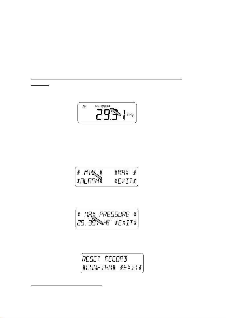
Example for Activating the Displays of Stored Maximum
Values
Call up the corresponding menu in the bottom section of the LCD
by touching the PRESSURE field.
Start by touching in the bottom section of the LCD.
Note: It is possible to display the stored minimum values
in the bottom section of the LCD in the same
fashion by touching the ٭MIN٭ field.
After touching ٭MAX٭, the stored value is displayed. Proceed by
touching the ٭MAX PRESSURE٭ field.
The displayed value can be reset to the current value by
touching *CONFIRM*. To advance without resetting, touch
٭EXIT٭.
This completes the Example
16

Example for Setting of Alarms by means of the HI Alarm
As in the example above, call up the corresponding menu in the
bottom section of the LCD by touching the PRESSURE field.
Proceed by touching ٭ALARM٭ in the section at the bottom of
the LCD.
Proceed with ٭HI AL٭ in the menu section.
Note: Setting of the low alarms is possible from here in
the same fashion by touching the ٭LO AL٭ field.
Set the high alarm value with ٭UP٭ or ٭DOWN٭.
Proceed with ٭ON/OFF٭.
Activate or deactivate the alarm with ٭ON٭ or ٭OFF٭.
Return to normal display by touching ٭EXIT٭.
Note: Activation or deactivation of the alarm (Display or deletion
of the (((•))) symbol) only pertains to the presently
displayed value, in this example it is PRESSURE.
This completes the Example
17

Note: Touching the PRESSURE section twice toggles the
display between Relative (rel) and Absolute (abs) air
pressure.
All setting and display options only pertain to the presently
displayed value.
10 Operating and Setting the Rain Function
Note: Besides the direct setting of the units for the rain amount in
the basic setup procedure, it is possible to toggle between
the following displays by touching the left part of the RAIN
section twice:
• Rain amount for the last hour
• Rain amount for the last 24 hours
• Rain amount for the last week
• Rain amount for the last month
Note: The rain amounts for the last week and the last
month do not represent the amounts collected up to
the present point of time, but to those for the last
complete week or the last complete month.
All setting and display functions pertain only to the
presently displayed value.
Important Note!
Operation and settings of the Rain function are essentially
identical to the ones described in Item 9 above. Therefore a
short description of the minor differences in regards to Item
9 will be a sufficient enough explanation.
• Since it is not necessary to display minimum rain values, the
menu does not offer the item ٭MIN٭ but ٭MAX٭ only to
display the various maximum rain amounts.
• Since no minimum rain values are stored, upon activating
the ٭ALARM٭, the display will immediately proceed to the
high alarm setting as described in section 9 above.
18

Note: The alarm option is only offered during display of the last
hour and last 24-hour rainfall amounts. No exact definition
of alarm time is possible for weekly and monthly rain
amounts; therefore these alarm functions have been
omitted.
• When touching the TOTAL field in the RAIN section, the total
rain amount accumulated since the last deletion is displayed.
This can be erased by touching ٭RAIN TOTAL٭ in the
bottom section of the LCD, followed by ٭CONFIRM٭.
11 Additional Information regarding the Outdoor
Temperature Display (Outdoor Temp)
Note: Touch the OUTDOOR field to toggle the display between
the following:
• Outdoor Temperature (Outdoor Temp)
• Wind Chill
• Dew Point
All setting and display options only pertain to the presently
displayed value.
12 Additional Information regarding the Wind Display
Note: Touch the WIND field to toggle the display between the
following:
• Wind Speed
• Wind Direction (Abbreviations of the compass rose
descriptions)
• Wind Direction (Degrees)
• Wind Gust
All setting and display options only pertain to the presently
displayed value.
19
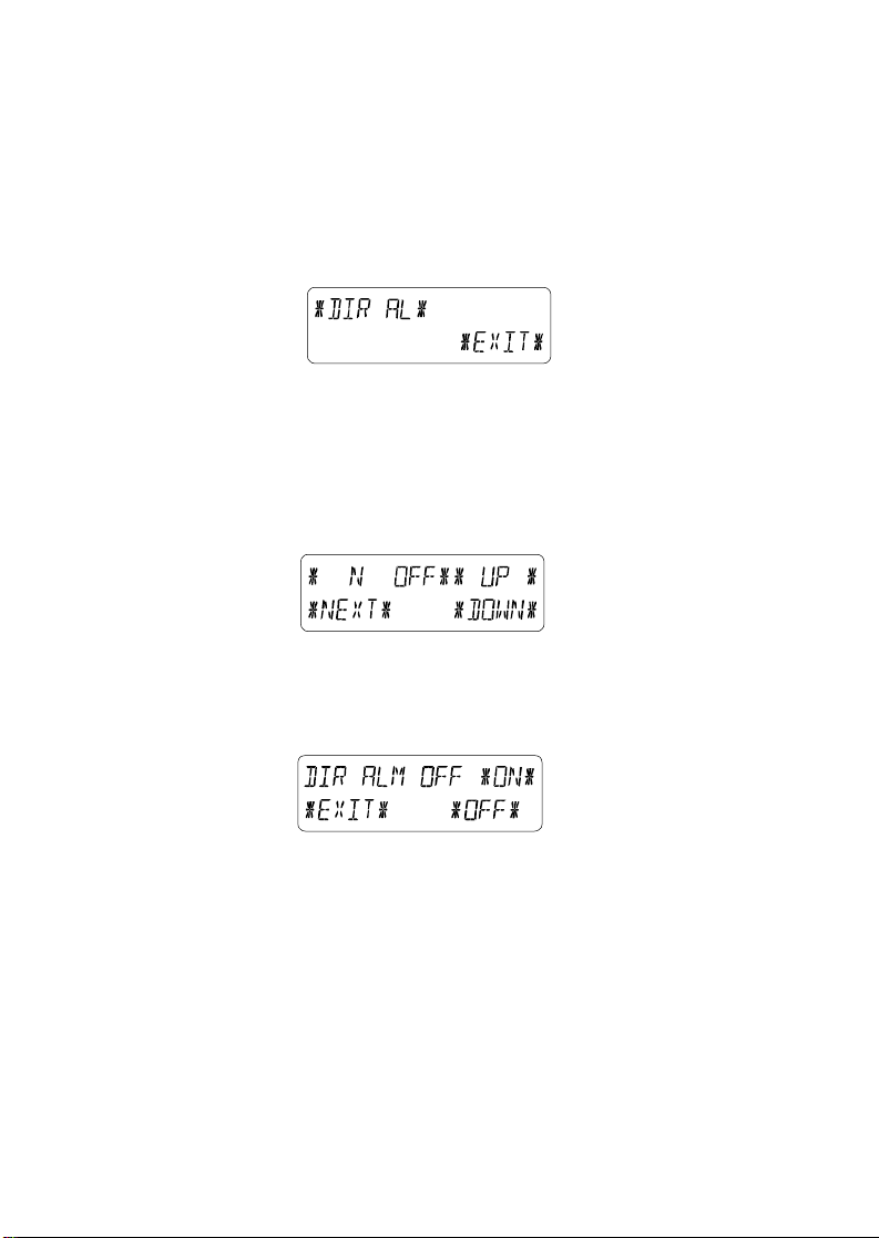
12.1 Operating and Setting the Wind Direction Alarm
In the Wind Direction display, the display of minimum or
maximum values is unnecessary. However it is possible to set
wind direction alarms.
Call up the corresponding menu in the bottom section of the LCD
by touching the center of the WIND field.
Proceed by touching ٭DIR AL٭.
In the following menu up to 16 separate alarms can be set
clockwise around the compass rose from N through NNW in
steps of 22.5°. (0° through 337.5°) Here the wind direction can
be selected by touching ٭UP٭ or ٭DOWN٭ and switched ON or
OFF with (Wind Direction) by touching ٭ON/OFF٭ in the upper
left part of the menu display.
The wind alarm feature can be enabled, or completely
deactivated by touching the ٭ON٭ and ٭OFF٭ fields in the menu
shown below.
Touch ٭EXIT٭ to return to normal display.
20

13 Operating and Setting the EL Backlight (light),
Buzzer (sound), and Alarm history (fields in the
WIND Section)
13.1 EL Backlight (Light)
For enhanced readability of the LCD the EL backlight can be
switched ON or OFF by touching the LIGHT field once. When the
backlight is switched to “Enabled”, it will glow for approximately
20 seconds every time any of the LCD sections is touched.
The switching condition (Enabled/Disabled) is shown in the
bottom section of the LCD for about 20 seconds.
Note: In case that the Base Station is battery operated, repeated
use of the EL backlight will result in a considerable
decrease of the life of the batteries. It is recommended
either to operate the Base Station with the included AC
adapter, or deactivate the EL backlight (see above).
13.2 Buzzer
The keypad beep and the audible alarms of the Base Station can
be switched ON or OFF by touching the BUZZER section.
The switching condition ON or OFF is displayed directly in the
BUZZER section as well as in the bottom section of the LCD for
about 20 seconds (Enabled/Disabled).
13.3 Alarm
Upon touching the ALARM field in the WIND section, all set and
activated alarms (except time alarm) will be shown numbered
and sorted according to time of appearance, along with ٭NEXT٭
and ٭EXIT٭. For each alarm preset, the time and date can be
displayed by touching the center of the bottom section of the
LCD.
21

14 PC Connection
In addition to the LCD monitor, the WS-3610 has the ability
to transfer all collected time and weather data to a PC via a
Com port connection. The supplied PC software provides
complete sets of history data, data graphing, and webpage
update capabilities.
14.1 Data Storage
For a comprehensive weather history, the Base Station allows
the internal storage of up to 1750 complete sets of weather data
with the recorded time and date. These data sets are stored in
non-volatile ring buffer memory (EEPROM) and will not be lost
even in case of an interruption of power supply (e. g. change of
batteries).
In the case that the memory capacity of the Base Station is
exhausted, the oldest data sets stored will be overwritten by the
new ones recorded.
14.2 Data Recall
The weather data stored can only be output, processed and
displayed on a PC. The user selectable storage interval of 1
minute to 12 hours for data sets can also only be performed on a
PC.
14.3 Connections and Software
An included COM port cable provides the means to connect the
Base Station to the PC. The “Heavy Weather Pro 3610” software
package (also included) must be installed on the PC.
This software allows the display of all present weather data with
graphic symbols. It further allows the display, storage and
printing of history data sets, whose volume exceeds the
maximum 1750 data sets of the Base Station, and is only limited
by the capacity of the PC’s main memory.
22

Furthermore the present weather data can be uploaded to web
sites by means of the “Web Publisher” software. History data can
be displayed as diagrams and graphs using the “Weather
Review” software.
For further details on the PC Connection please see the Help
File on the installation disk for the software.
23

16 TX11U Rain Sensor
The TX11U rain sensor is used in conjunction with the
TX12U wind sensor and TX13U thermo/hygro sensor to
gather and transmit information to the wireless weather
station.
INVENTORY OF CONTENTS
1. TX11U rain sensor
2. Mounting hardware
SETTING UP
BATTERY INSTALLATION
The first step to powering up the weather station is to insert the
connector (RJ11) at the end of the wire attached to the wind
speed sensor to the remote thermo/hygro sensor. Please
ensure when doing this that the connector is inserted with the
proper orientation. When seated properly you will hear the
connector ‘click’ in place.
The Rain Sensor does not need batteries to operate. Simply
insert the telephone plug (RJ-11) of the rain sensor into the
receptacle on the remote thermo/hygro sensor.
Sensor sockets
24

Important: To avoid operating problems, please take note of
battery polarity if inserting any batteries. Also do not press any
buttons after start up until all sensor information has been
displayed and the radio controlled time has set. Doing so may
interrupt communication between the sensors and display or
interrupt the WWVB time reception.
1. Pull away the rain cover of the thermo-hygro sensor to
reveal the three sockets (for the wind sensor, rain sensor
and the base station)
2. Connect the attached cables of wind and rain sensors to the
corresponding sockets of the thermo-hygro sensor by
clicking them into place
3. Open the battery cover of the thermo-hygro sensor located
below the three sockets and insert 2 x AA, IEC LR6, 1.5V
batteries and close the cover
4. Open the base station’s battery cover located at the back of
the unit and insert 3 x AA, IEC LR6, 1.5V batteries into the
battery compartment and close the battery cover
Every time the thermo-hygro sensor is powered up (for example
after a change of batteries), a random security code is
transmitted and this code must be synchronized with the base
station to receive weather data.
Note for WWVB Radio Controlled Time:
The time and date display is based on the signal provided by the
highly accurate government operated atomic clock in Ft. Collins,
Colorado. This radio-controlled clock does not only provide for
the weather station’s time and date display but also functions as
the time and date source for all of this weather station’s memory
values using time and date information.
25

Mounting the Rain Sensor
Funnel Portion
Base portion
For accurate results, the rain sensor should be securely mounted
onto a horizontal surface about 2-3ft above the ground and in an
open area away from trees or other coverings where rainfall may
be reduced causing inaccurate readings.
When securing into place, check that rain excess will not collect
and store at the base of the unit but can flow out between the
base and the mounting surface (test by pouring clean water).
After mounting the rain sensor, connect the cable to the thermohygro sensor at the corresponding socket so power supply can
be received and data be transmitted to the base station
The rain sensor is now operable. For testing purposes, very
slowly pour a small amount of clean water into the rain
sensor funnel. The water will act as rainfall and will be
received and displayed at the base station after about 2
minutes delay i.e. when the reading interval is reached.
MAINTENANCE AND CARE
1. Extreme temperatures, vibrations, and shock should be
avoided to prevent damage to the units
26

2. Clean displays and units with a soft, damp cloth. Do not use
solvents or scouring agents, they may mark the displays and
casings
3. Do not submerge in water.
4. Do not subject the units to unnecessary heat or cold by
placing them in the oven or freezer.
5. Opening the casings invalidates the warranty. Do not try to
repair the unit. Contact La Crosse Technology for repairs.
6.
17 TX12U Wind Sensor
The TX12U wind sensor is used in conjunction with a
thermo/hygro sensor to gather and transmit information to the
wireless weather station. The TX12U wind sensor measures the
wind speed and direction and sends the information to the
remote sensor. This sensor then sends all outdoor weather
information from the outdoor sensor(s) to the display indoors.
INVENTORY OF
CONTENTS
3. TX12U wind sensor
4. Mounting bracket
5. Mounting hardware
SETTING UP
First, choose to use the
adaptor (included in this set) or batteries for operation. Both
these methods allow for operation using wireless 433MHz
transmission or cable connection between the base station and
the sensor(s) and sensor. Setting up for both methods is as
follows:
27

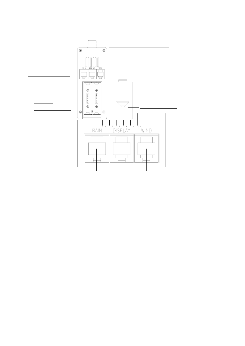
Base Station:
Battery compartment
Socket for
Adaptor
Socket for
remote
sensor
PC COM
Port
Setting up using batteries:
Sensor sockets
28

Important:
To avoid operating problems, please take note of battery polarity if
inserting any batteries. Also do not press any buttons after start up
until all sensor information has been displayed and the radiocontrolled time has set. Doing so may interrupt communication
between the sensor(s), sensor, and display or interrupt the WWVB
time reception.
1. Pull away the rain cover of the thermo/hygro sensor to reveal
the 3 sockets (for the wind sensor, rain sensor (if applicable),
and the base station)
2. Connect the attached cables of the wind sensor to the
corresponding sockets of the thermo/hygro sensor by
clicking them into place
3. Open the battery cover of the thermo/hygro sensor located
below the 3 sockets and insert 2 x AA, 1.5V batteries and
close the cover
4. Open the base station’s battery cover located at the back of
the unit and insert 3 x AA, 1.5V batteries into the battery
compartment and close the battery cover
Setting up using the AC adaptor:
1. Power up the sensor(s) and sensor as described in setting
up using batteries
2. Using the AC adaptor (included), plug it into the mains outlet
and power up the base station by inserting the adaptor jack
into the DC 6.0V socket located on the side of the base
station
Every time the thermo/hygro sensor is powered up (for example
after a change of batteries), a random security code is
transmitted and this code must be synchronized with the base
station to receive weather data.
When the base station is powered up, a short beep will sound
and all LCD segments will light up for about 5 seconds before it
enters into a 15 minute learning mode to learn the sensors
security code. After the learning mode (or by pressing the
29

“MIN/MAX” key at anytime), the base station will start the WWVB
radio-controlled time reception.
Note for WWVB Radio-Controlled Time:
The time and date display is based on the signal provided by the
highly accurate government operated atomic clock in Ft. Collins,
Colorado. This radio-controlled clock does not only provide for
the weather station’s time and date display but also functions as
the time and date source for all of this weather station’s memory
and history values using time and date information.
Mounting the wind sensor onto a mast
Wind-vane
Wind-fan
First, check that the wind-fan and the wind-vane can rotate freely
before mounting the unit. For correct and accurate readings it is
important to mount the sensor so that the front (marked E) is
pointing in East-West direction. The wind sensor should now be
mounted using the screws provided onto a mast to allow the
wind to travel around the sensor unhindered from all directions
(ideal mast size should be from Ø.63” – Ø1.3”).
Once the wind sensor is fixed onto the mast, connect the
cable to the corresponding remote sensor socket so that
operating power can be supplied and data can be
transmitted to the base station.
MAINTENANCE AND CARE
1. Extreme temperatures, vibrations, and shock should be
avoided to prevent damage to the units
30

2. Clean displays and units with a soft, damp cloth. Do not use
solvents or scouring agents, they may mark the displays and
casings
3. Do not submerge in water.
4. Do not subject the units to unnecessary heat or cold by
placing them in the oven or freezer.
5. Opening the casings invalidates the warranty. Do not try to
repair the unit. Contact La Crosse Technology for repairs.
18 TX13U Thermo/Hygro Sensor
The TX13U Thermo/Hygro Sensor is used in conjunction with the
TX12U wind sensor and TX11U rain sensor to gather and
transmit information to the WS-3610 series wireless weather
station. The TX13U Thermo/Hygro sensor measures the
temperature and humidity of the location it is mounted. This
sensor then transmits all outdoor weather information from the
three outdoor sensors to the display indoors.
INVENTORY OF CONTENTS
1. TX13U Thermo/Hygro Sensor
2. Mounting hardware
Figure B
Figure A
31

SETTING UP
First, choose to use the adaptor (included in this set) or batteries
for operation. Both these methods allow for operation using
wireless 433MHz transmission or cable connection between the
base station and the sensors and setting up for both methods is
as follows:
Base Station:
Socket for
Adaptor
Socket for
ThermoHygro Sensor
PC COM
Port
Battery compartment
32
Setting up using batteries:
Thermo/Hygro Sensor
Sensor sockets
Battery
Compartment
Important:
To avoid operating problems, please take note of battery polarity
if inserting any batteries. Also do not press any buttons after
start up until all sensor information has been displayed and the
radio controlled time has set. Doing so may interrupt
communication between the sensors and display or interrupt the
WWVB time reception.
1. Pull away the rain cover of the thermo/hygro sensor to reveal
the three sockets (for the wind sensor, rain sensor and the
base station)
2. Connect the attached cables of wind and rain sensors to the
corresponding sockets of the thermo/hygro sensor by
clicking them into place
3. Open the battery cover of the thermo/hygro sensor located
below the three sockets and insert 2 x AA, IEC LR6, 1.5V
batteries and close the cover
Battery Cover
Sensor sockets
33

4. Open the base station’s battery cover located at the back of
the unit and insert 3 x AA, IEC LR6, 1.5V batteries into the
battery compartment and close the battery cover
Setting up using the AC adaptor:
1) Power up all the sensors as described in setting up using
batteries above
2) Using the AC adaptor (included), plug it into the mains outlet
and power up the base station by inserting the adaptor jack
into the DC 6.0V socket located on the side of the base
station
Every time the thermo/hygro sensor is powered up (for example
after a change of batteries), a random security code is
transmitted and this code must be synchronized with the base
station to receive weather data.
When the base station is powered up, a short beep will sound
and all LCD segments will light up for about 5 seconds before it
enters into a 15 minute learning mode to learn the sensors
security code. After the learning mode (or by pressing the
MIN/MAX key at anytime), the base station will start the WWVB
radio controlled time reception.
Note for WWVB Radio Controlled Time:
The time and date display is based on the signal provided by the
highly accurate government operated atomic clock in Ft. Collins,
Colorado. This radio controlled clock does not only provide for
the weather station’s time and date display but also functions as
the time and date source for all of this weather station’s memory
and history values using time and date information.
34

Mounting the thermo/hygro Sensor
Rain Cover
Wall Bracket
Main Unit
An ideal mounting place for the thermo/hygro sensor would
be the outer wall beneath the extension of a roof, as this will
protect the sensor from direct sunlight and other extreme
weather conditions.
To wall mount, use the 2 screws to affix the wall bracket to the
desired wall, plug in the thermo/hygro sensor to the bracket and
secure both parts by the use of the supplied screw and ensure
that the cables from the wind and rain sensors are correctly
plugged in otherwise data transmission errors could occur.
NOTE: For best 433 MHz reception mount the thermo/hygro
sensor on an outside wall near the location of the base station.
MAINTENANCE AND CARE
1. Extreme temperatures, vibrations, and shock should be
avoided to prevent damage to the units
35

2. Clean displays and units with a soft, damp cloth. Do not use
solvents or scouring agents, they may mark the displays and
casings
3. Do not submerge in water.
4. Do not subject the units to unnecessary heat or cold by
placing them in the oven or freezer.
5. Opening the casings invalidates the warranty. Do not try to
repair the unit. Contact La Crosse Technology for repairs.
6. Place the outdoor sensor in a well-shaded area that is
protected from direct rainfall as it will read high if exposed to
the sun. If the sensor gets too wet it won’t receive accurate
humidity readings. Take care to ensure that it will not be
exposed to heavy rainfall.
36

15 Technical Data
15.1 Outdoor Data:
Transmission Range in Open Field:.....up to. 330 ft max.
Measuring Interval Outdoor Data:........every 20 s
Temperature Range: ............................-40 °F to 139.8 °F
(Display “OFL” outside
this range)
Resolution: ...........................................0.1 °F
Measuring Range Rel. Humidity: .........1% to 99%
Resolution: ...........................................1%
Rain Volume Display:...........................0 to 39.4 in (1 hr, 24 hrs.)
0 to 98.4 in (last week,
last month)
0 to 393.7 in (total
volume)
Resolution: ...........................................approx. 0.02 in
Wind Speed..........................................0 to 111.8 mph or 1 to 50
m/s
Resolution: ...........................................0.1 m/s
Wind Direction:.....................................Graphic Resolution 22.5
Degrees,
Numeric Resolution
Character Format
15.2 Data Transmission by 433 MHz Signal:
Measuring Interval Thermo-Hygro Sensor:.......................
128 s (at Wind speed ≤ 6.2 mph) or 32 s (at Wind speed > 6.2
mph, or on Wind Gust display); 10 Min. (if the Base Station does
not receive any data after 5 successive attempts all outdoor
displays except the rain amount revert to “---“)
15.3 Data Transmission by Cable:
Measuring Interval Thermo-Hygro Sensor:..........32 s
37

15.4 Indoor Data:
Measuring Interval Indoor Data:...........every 20 s
Temperature Range: ............................14.2 °F to 139.8 °F
(Display “OFL” outside
this range)
Resolution: ...........................................0.1 °F
Measuring Range Rel. Humidity: .........1% to 99%
Resolution: ...........................................1%
Measuring Range Air Pressure:...........8.86 inHg to 32.45 inHg
Resolution: ...........................................0.003 inHg
Alarm Duration: ....................................about 2 minutes
15.5 Power Supply:
Base Station:
Batteries: ..............................................3 ea. 1.5 V Batteries Type
AA, IEC LR6 (Alkaline
Batteries recommended,
Life Cycle without EL
backlight approx. 1 year)
or AC power: ........................................AC Adapter INPUT
120VAC / 60HZ (use only
the included AC Adapter.
Recommended for PC
Connection and
frequent use of EL
Backlight)
Thermo/Hygro Sensor:
Batteries: ..............................................2 ea. 1.5 V Batteries Type
C (Alkaline Batteries
recommended, Life Cycle
approx. 2.5 years)
or ..........................................................Power provided via Cable
from the Base Station by
using the AC Adapter
38

15.6 PC Connection:
Wiring: ..................................................COM Port Cable
(included)
Data Processing:..................................by PC only
Software: ..............................................“Heavy Weather Pro
3600“ (included)
Storage Intervals: .................................1 min through 12 h,
settable
Data Volume:
Base Station:........................................1750 Data Sets max. in
Ring Buffer EEPROM
PC: .......................................................Volume of Main Memory
max.
15.7 Dimensions:
Base Station:........................................8.86 x 6.10 x 1.38 in
Thermo-Hygro-Sensor: ........................5.35 x 2.87 x 2.81 in
Rain Sensor:.........................................5.51 x 5.39 x 2.76 in
Wind Sensor:........................................11.46 x 7.76 x 2.36 in
39

WARRANTY INFORMATION
La Crosse Technology, Ltd provides a 1-year limited warranty on this
product against manufacturing defects in materials and workmanship.
This limited warranty begins on the original date of purchase, is valid
only on products purchased and used in North America and only to the
original purchaser of this product. To receive warranty service, the
purchaser must contact La Crosse Technology, Ltd for problem
determination and service procedures. Warranty service can only be
performed by a La Crosse Technology, Ltd authorized service center.
The original dated bill of sale must be presented upon request as proof
of purchase to La Crosse Technology, Ltd or La Crosse Technology,
Ltd’s authorized service center.
La Crosse Technology, Ltd will repair or replace this product, at our
option and at no charge as stipulated herein, with new or reconditioned
parts or products if found to be defective during the limited warranty
period specified above. All replaced parts and products become the
property of La Crosse Technology, Ltd and must be returned to La
Crosse Technology, Ltd. Replacement parts and products assume the
remaining original warranty, or ninety (90) days, whichever is longer. La
Crosse Technology, Ltd will pay all expenses for labor and materials for
all repairs covered by this warranty. If necessary repairs are not
covered by this warranty, or if a product is examined which is not in
need or repair, you will be charged for the repairs or examination. The
owner must pay any shipping charges incurred in getting your La
Crosse Technology, Ltd product to a La Crosse Technology, Ltd
authorized service center. La Crosse Technology, Ltd will pay ground
return shipping charges to the owner of the product to a USA address
only.
Your La Crosse Technology, Ltd warranty covers all defects in material
and workmanship with the following specified exceptions: (1) damage
caused by accident, unreasonable use or neglect (including the lack of
reasonable and necessary maintenance); (2) damage occurring during
shipment (claims must be presented to the carrier); (3) damage to, or
deterioration of, any accessory or decorative surface; (4) damage
resulting from failure to follow instructions contained in your owner’s
manual; (5) damage resulting from the performance of repairs or
alterations by someone other than an authorized La Crosse
Technology, Ltd authorized service center; (6) units used for other than
home use (7) applications and uses that this product was not intended
or (8) the products inability to receive a signal due to any source of
interference.. This warranty covers only actual defects within the
product itself, and does not cover the cost of installation or removal from
a fixed installation, normal set-up or adjustments, claims based on
40

misrepresentation by the seller or performance variations resulting from
installation-related circumstances.
LA CROSSE TECHNOLOGY, LTD WILL NOT ASSUME LIABILITY
FOR INCIDENTAL, CONSEQUENTIAL, PUNITIVE, OR OTHER
SIMILAR DAMAGES ASSOCIATED WITH THE OPERATION OR
MALFUNCTION OF THIS PRODUCT. THIS PRODUCT IS NOT TO BE
USED FOR MEDICAL PURPOSES OR FOR PUBLIC INFORMATION.
THIS PRODUCT IS NOT A TOY. KEEP OUT OF CHILDREN’S
REACH.
This warranty gives you specific legal rights. You may also have other
rights specific to your State. Some States do no allow the exclusion of
consequential or incidental damages therefore the above exclusion of
limitation may not apply to you.
For warranty work, technical support, or information contact:
La Crosse Technology, Ltd
2809 Losey Blvd. S.
La Crosse, WI 54601
Phone: 608.782.1982
Fax: 608.796.1020
e-mail:
support@lacrossetechnology.com
(warranty work)
sales@lacrossetechnology.com
(information on other products)
web:
www.lacrossetechnology.com
Questions ? Instructions? Please visit:
www.lacrossetechnology.info/3610
All rights reserved. This handbook must not be reproduced in any form, even in
excerpts, or duplicated or processed using electronic, mechanical or chemical
procedures without written permission of the publisher.
This handbook may contain mistakes and printing errors. The information in this
handbook is regularly checked and corrections made in the next issue. We
accept no liability for technical mistakes or printing errors, or their consequences.
All trademarks and patents are acknowledged.
41
 Loading...