


PROFESSIONAL WEATHER CENTER
WS-1610
TWC
-
IT
Quick Set up Manual

1
Quick Set Up Manual – Professional Weather Center
Using 915MHz wireless transmission of weather data, this unique weather station can
be powered using batteries for all your weather needs in the home or office.
Carefully open and check that the following contents are complete:
Item: Consisting of: Fittings: Illustration:
Base
Station
1) Main unit

2
ThermoHygro
Sensor
Wind
Sensor
1) Main unit
2) Rain
protection
cover
1) Main unit with
wind vane
2) 32ft cable
(already
attached the
main unit)
3) Mast holder
1) Wall mounting
screws
2) Plastic
anchors for
screws
3) 2 x cable ties
1) 1 x U-bolts for
mast holder
2) 2 x Washers
3) 2 x Nuts
4)
2 x cable ties
Rain
Sensor
1) Base and
funnel
2) 32ft cable
(already
attached the
main unit)
1) 2 x Screws
and Plastic
anchors

3
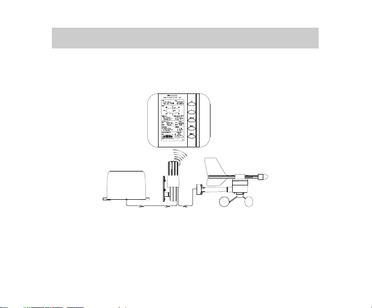
Setting Up:
Important: Operating power is supplied to both the wind and rain sensors by the
thermo-hygro sensor
Thermo-Hygro Sensor
Setting up using batteries:
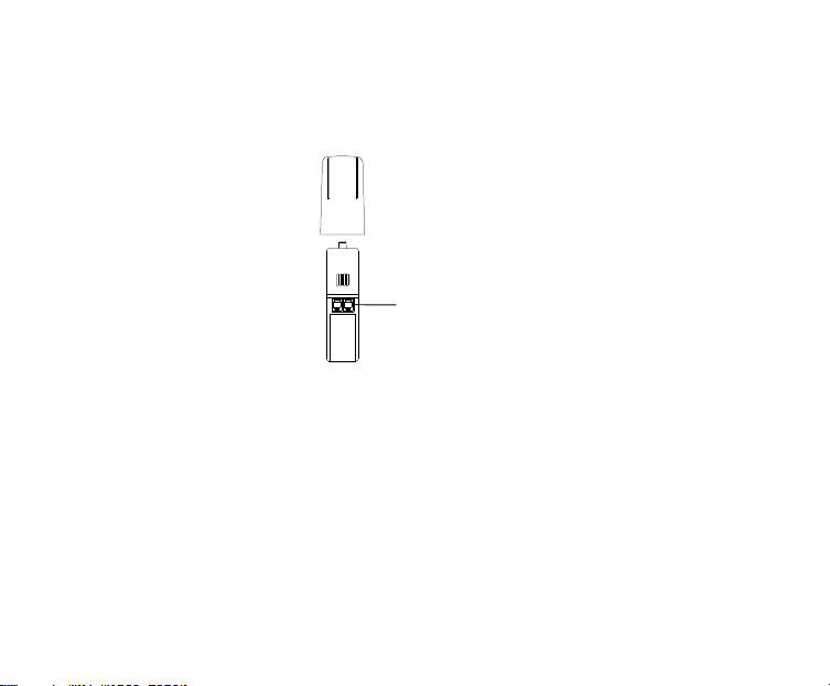
1) Sensors: Pull and remove the protective rain cover of the Thermo-Hygro
Sensor to reveal 2 socket ports and the battery cover. Insert the cables of the
wind and rain sensors in the correctly marked sockets. Slide open the battery
Sockets for wind
and rain sensor
Weather center
Battery compartment

4
compartment and checking the correct polarity insert 2 x AA IEC, LR6 1.5V
batteries and replace the cover and rain cover
2) Base Station: Now open the battery cover at the back of the unit and checking
the correct polarity insert 3 x AA IEC, LR6 1.5V batteries and replace the battery
cover
Performing a function test and Setting time manually:
1. After powering up the units, the base station has to synchronize to the sensors
before the weather data can be received.
2. Afterwards, the W eather Station will start receiving data from the transmitter.
The outdoor temperature, humidity, windchill and wind speed should then be
displayed on the Weather Station. If this does not happen after 30 seconds, the
batteries will need to be removed from both units. You will have to start again
from the beginning.
3. You may then check all cables for correct connection and all components for
correct function by manually turning the wind-gauge, moving the weather-vane,
tilting the rain sensor to hear the impact of the internally moving seesaw, etc.
4. Time and date shall be manually set.
5. After the Weather Station has been checked for correct function with regard to
the above points and found fit, the initial set up of the weather station system is
finished and the mounting of the system components can take place. It must be
ensured however that all components work properly together at their chosen
mounting or standing locations. If e.g. there appear to be problems with the 915
MHz radio transmission, they can mostly be overcome by slightly changing the
mounting locations.

5
Note:
•
Should any outdoor data not be received from the sensors (when “- - -“ is
displayed), check all cables are correctly installed. Then user shall remove the
batteries from all units and redo the set-up procedures after about 5 minutes.
•
Wind speeds that read zero does not mean reception failure, it simply means
that there was no wind at the time of reading the data.
Mounting the units:
Users must take their surroundings into consideration before deciding which method
is best suited for them. Connection by cable is advantageous in that data from the
sensors to the base station is interference free. Using 915MHz wireless transmission
gives users little restriction on placement as that all units can be positioned virtually
anywhere to within a 330 ft radius of the base station. You must decide which method
is best suited to you. For cable connecting, please ensure that the cable included in
this set meets with your distance requirements (see accessories in the main user
manual for adding extension cables).
Important: Ensure all signals can be received and/or all cable distances meet with
your requirements at the point of fixing particularly before you start drilling any
mounting holes.
Wind sensor
Secure the main unit to the shaft of the mast holder using the single screw provided
with the front of the sensor (marked E) facing in the East-West direction otherwise

6
wind direction will not be accurate. Now fix the entire unit to a suitable mast using the
U-bolt, washers and nuts found in this set.
Note: For best results mount the wind sensor onto a mast to allow the wind to freely
travel from all directions to enable an accurate reading (ideal mast size should be
5
from Ø
/8” to 11/4”). Ensure that the cable of the wind sensor meets your distance
requirements
Rain sensor
The rain sensor should be mounted horizontally about 2-3ft off from the ground in an
open area away from trees or other coverings to allow rain to fall naturally for an
accurate reading.
Note: For best results ensure the base is horizontal to allow maximum drainage of
any collected rain
Thermo-hygro Sensor
To wall mount the thermo-hygro sensor, fix the wall holder onto the desired wall (2
screws are supplied), plug the sensor firmly into the wall holder and then carefully
replace the rain cover back over the thermo-hygro sensor.
Note: After mounting the units, should the weather data not be received, user may
need to remove the batteries from all units and redo the set-up procedures after about
5 minutes.

7
WARRANTY
For warranty work, technical support, or information contact:
All rights reserved. This handbook must not be reproduced in any form, even in excerpts, or
duplicated or processed using electronic, mechanical or chemical procedures without written
permission of the publisher.
La Crosse Technology, Ltd
2809 Losey Blvd. South
La Crosse, WI 54601
Phone: 608.782.1610
Fax: 608.796.1020
support@lacrossetechnology.com
sales@lacrossetechnology.com
(information on other products)
www.lacrossetechnology.com
For more information, please visit:
www.lacrossetechnology.com/1610itc
e-mail:
(warranty work)
web:
Springfield / Lacrosse Canada.
1-800-661-6721
5151 Thimens Rd.
Montreal, Quebec
H4R 2C8

8
This handbook may contain mistakes and printing errors. The information in this handbook
is regularly checked and corrections made in the next issue. W e accept no liability for
technical mistakes or printing errors, or their consequences.
All trademarks and patents are acknowledged.

9
Ce poste météo unique, qui utilise la transmission sans fil 915MHz des données
météo, peut être alimenté par piles pour remplir tous vos besoins chez vous ou au
bureau.
Ouvrir et vérifier soigneusement que l’ensemble comprend toutes les parties
suivantes:
Article: Consiste en: Accessoires: Illustration:
Poste de
base
1) Appareil
principal
Montage rapide – Centre Météo Professionnel

10
Capteur
thermohygro
Capteur
vent
Capteur
pluie
1) Appareil
principal
2) Capuchon
anti-pluie
1) Appareil
principal avec
girouette
2) Câble de 32 ft
(déjà fixé à
l’appareil
principal)
3) Support
poteau
1) Base et
entonnoir
2) Câble de 32ft
(déjà fixé à
l’appareil
principal)
1) Vis
d’installation
murale
2) Chevilles en
plastique pour
les vis
3) 2 x frettes de
câblage
1) 1 x Boulons en
U pour support
poteau
2) 2 x Rondelles
3) 2 x Boulons
4) 2 x frettes de
câblage
1) 2 x Vis et
chevilles

11
Montage:
Important: Les capteurs vent et pluie sont alimentés par le capteur thermo-hygro.
Capteur thermo-hygro
Montage avec les piles:
1) Capteurs: Tirer et enlever le capuchon anti-pluie du capteur thermohygro pour révéler deux prises et le couvercle des piles. Insérer les
câbles des capteurs vent et pluie dans les prises conformément aux
Prises pour
capteur vent et
pluie
Poste de base
Logement des piles

12
indications. Ouvrir le couvercle du logement en le faisant coulisser et
installer 2 piles AA/R6 1,5V en respectant les polarités. Remettre le
couvercle en place.
2) Poste de base: Ensuite ouvrir le couvercle des piles au dos de l’appareil
et installer 3 piles AA/R6 1,5V en respectant les polarités. Remettre le
couvercle en place.
Effectuer un test et règler l’heure manuellement:
1. Après que les piles sont en place dans les appareils, le poste de base doit
synchroniser les capteurs avant de recevoir les données météo.
2. Ensuite, le poste météo commence à recevoir les données de l’émetteur. La
température extérieure, l’humidité, le facteur vent et la vitesse du vent devraient
s’afficher sur le poste météo. S’ils ne s’affichent pas dans les 30 secondes,
retirer les piles des deux appareils et recommencer à partir du début.
3. Il est conseillé de vérifier la bonne connexion de tous les câbles et de s’assurer
que tous les éléments fonctionnent correctement : tourner manuellement la
jauge vent, bouger la girouette, incliner le capteur pluie pour entendre le
balancier interne, etc.
4. Règler manuellement l’heure et la date.
5. Quand on s’est assuré que le poste météo fonctionne correctement en ce qui
concerne les points ci-dessus, le montage initial est terminé et il est possible de
mettre les différents éléments du système en place. Cependant, il faut s’assurer
que tous les éléments fonctionnenrt correctement aux lieux dans lesquels ils
doivent être installés. Par exemple, si des problèmes de transmission radio 915

13
MHz apparaissent, il est souvent facile de les règler en changeant légèrement
les appareils de place.
Note:
•
En cas de non-réception des données extérieures des capteurs (quand “- - “ s’affiche), vérifier que tous les câbles sont installés correctement. Ensuite,
retirer les piles de tous les appareils et recommencer la procédure de montage
5 minutes plus tard.
•
Une vitesse de vent affichant zéro n’indique pas une mauvaise réception. Ceci
indique simplement qu’il n’y a pas de vent au moment de la lecture des
données.
Mise en place des appareils:
Prendre l’environnement en considération avant de décider quelle méthode convient
le mieux . La connexion par câble est avantageuse en ce sens que les données sont
transmises des capteurs au poste de base sans aucune interférence. L’uilisation de la
transmission sans fil 915MHz permet de placer les appareils pratiquement n’importe
où dans un rayon de 330ft (110m) du poste de base. C’est à l’utilisateur de décider
quelle méthode lui convient le mieux. Pour la connexion par câble, s’assurer que le
câble de 10 m inclus avec l’appareil convient à la distance prévue (se reporter aux
accessoires dans le mode d’emploi principal pour ajouter des prolongateurs).
Important: S’assurer de la bonne réception de tous les signaux et/ou que la distance
câblée est adéquate avant de percer des trous pour fixer les appareils en place.

14
Capteur vent
Fixer l’appareil principal à la tige du support de poteau à l’aide de la vis fournie sur le
devant du capteur (marqué E) en l’installant face à la direction Est-Ouest, sinon la
direction du vent ne sera pas précise. Fixer ensuite tout l’appareil sur un poteau
adéquat à l’aide du boulon en U, des rondelles et des boulons fournis avec l’appareil.
Note: Pour de meilleurs résultats, fixer le capteur vent sur un poteau pour permettre
au vent de circuler librement de toutes les directions et permettre des relevés précis
(la taille idéale du poteau est entre Ø
câble du capteur vent est d’une longueur adéquate.
5
/8” (16 mm) et 11/4” (33 mm)). S’assurer que le
Capteur pluie
Le capteur pluie devrait être installé horizontalement à 2-3ft (60-90cm) du sol dans un
lieu dégagé à l’écart des arbres ou autres couvertures pour permettre à la pluie de
tomber naturellement et obtenir des relevés précis.
Note: Pour de meilleurs résultats, s’assurer que la base est horizontale pour
permettre un écoulement maximum de la pluie collectée.
Capteur thermo-hygro
Pour fixer le capteur thermo-hygro sur un mur, fixer le support mural à l’endroit désiré
(2 vis sont fournies); connecter solidement le capteur au support mural et remettre
soigneusement le capuchon en place sur le capteur thermo-hygro.

15
Note: En cas de non-réception des données après que les appareils ont été mis en
place, retirer les piles de tous les appareils et recommencer la procédure de montage
après 5 minutes environ.
GARANTIE
Pour toute intervention sous garantie, support technique ou information, veuillez contacter
La Crosse Technology, Ltd
2809 Losey Blvd. South
La Crosse, WI 54601
Phone: 608.782.1610
Fax: 608.796.1020
support@lacrossetechnology.com
(interventions sous garantie)
sales@lacrossetechnology.com
(informations sur les autres produits)
www.lacrossetechnology.com
Pour d'ample informations, visiter:
www.lacrossetechnology.com/1610itc
e-mail :
site web :
Springfield / Lacrosse Canada.
1-800-661-6721
5151 Thimens Rd.
Montreal, Quebec
H4R 2C8

16
Tous droits réservés. Ce manuel ne peut être ni reproduit sous quelque forme que ce soit,
même sous forme d'extraits, ni copié, ni traité par procédure électronique, mécanique ou
chimique, sans l'accord écrit de l'éditeur.
Ce manuel peut contenir des erreurs et fautes d'impression. Les informations contenues
dans ce manuel sont régulièrement vérifiées, les corrections étant apportées à l'édition
suivante. Nous n'acceptons aucune responsabilité pour les erreurs techniques ou
d'impression ou pour leurs conséquences.
Toutes les marques commerciales et brevets sont reconnus.
EJMA1610L220

PROFESSIONAL WEATHER CENTER
WS-1610TWC-IT
Operation Manual
PROFESSIONAL WEATHER CENTER
WS-1610TWC-IT
Operation Manual

Table of Contents
Topic Page
Features 3
Setting up 6
Function keys 12
LCD Screen 14
Manual Setting 16
Time alarm setting 24
Weather alarm operations 25
Hysteresis 31
Weather forecast and weather tendency 32
Wind direction and wind speed measurement 36
Rainfall measurement 37
Viewing history data 37
Viewing the min/ max weather data 39
Switch On/ Off buzzer 46
Outdoor transmission 915 MHz reception 48
Positioning 49
Care and Maintenance 53
Specification 54
Warranty Info 56
1

PROFESSIONAL WEATHER CENTER
is the
transmission technology, exclusively
immediate update (every 4 seconds!)
Instruction Manual
Congratulations on purchasing this state-of-the-art Professional Weather Center as an
example of excellent design and innovative technology. Featuring time, date,
calendar, weather forecast, wind direction and speed, rainfall, outdoor temperature
and outdoor humidity, air pressure and various alarm settings for different weather
conditions, this Weather Center will provide you with extensive weather information
and forecast.
This product offers:
INSTANT TRANSMISSION
state-of-the-art new wireless
designed and developed by LA
CROSSE TECHNOLOGY. INSTANT
TRANSMISSION
of all your outdoor data measured
from the transmitters: follow your
climatic variations in real-time!
offers you an
2

FEATURES:
Weather Center
LCD
•
Time display (manual setting)
•
12/24 hour time display
•
Calendar display (weekday, date, month, year)
•
Time alarm function
•
Weather forecasting function with 3 weather icons and weather tendency
Function keys
indicator
•
Outdoor temperature display in ºF/°C
•
Outdoor Humidity display as RH%
•
MIN/MAX value of outdoor temperature and humidity display with time & date
of recording
Foldout stand II
Foldout stand I
Hanging hole
Battery compartment
cover
3

•
Low/High outdoor temperature and humidity alarm
•
Relative air pressure displayed in inHg or hPa
•
Air pressure tendency indicator for the past 12 hours (bargraph format)
•
LCD contrast selectable
•
Low battery indicator
•
Wind direction displayed in 16 steps
•
Wind speed displayed in mph, km/h, or m/s, and Beaufort scale
•
Wind chill displayed in °F of °C
•
Max wind speed displayed with time & date of recording
•
High alarm function for wind speed
•
Manual reset of outdoor temperature/ humidity, pressure and wind chill data
•
Total rainfall displayed in mm or inch
•
Storm warning alarm
•
Buzzer on/off selectable
•
Storage of 200 sets of history weather data recorded in 3-hour intervals
•
Wireless transmission at 915 MHz
•
Transmission range up to 330 feet (100 meters)
Thermo-hygro Sensor
•
Remote transmission of the outdoor temperature and humidity
to the Weather Center at 915 MHz
•
Weather-resistant casing
•
Wall mounting case (to be mounted in a sheltered place. Avoid
direct rain and sunshine)
4

Wind Sensor
Rain Sensor
•
Connected to the thermo-hygro sensor by cable
•
Can be installed onto a mast or a horizontal panel
•
Connected to the thermo-hygro sensor by cable
•
To be mounted onto a horizontal panel
5
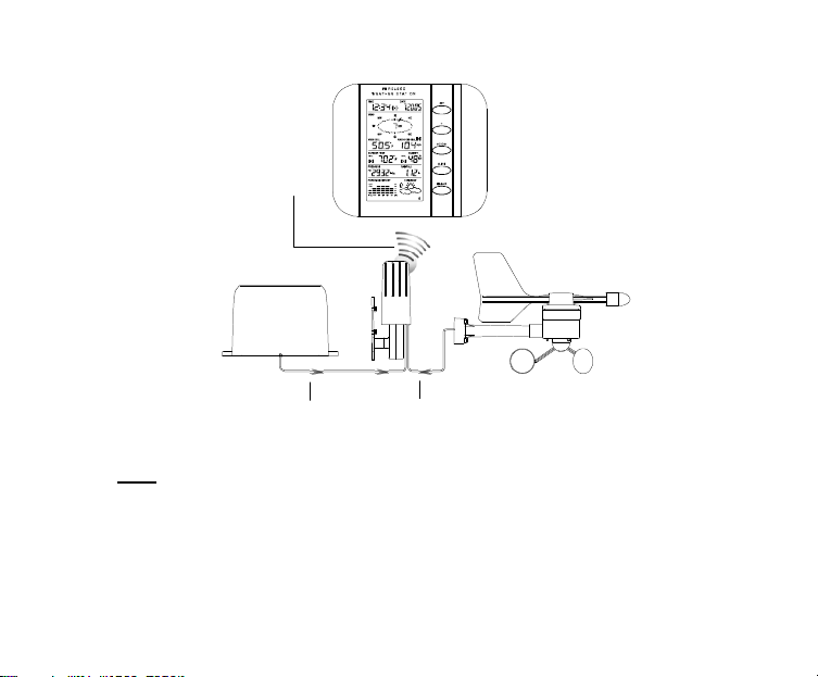
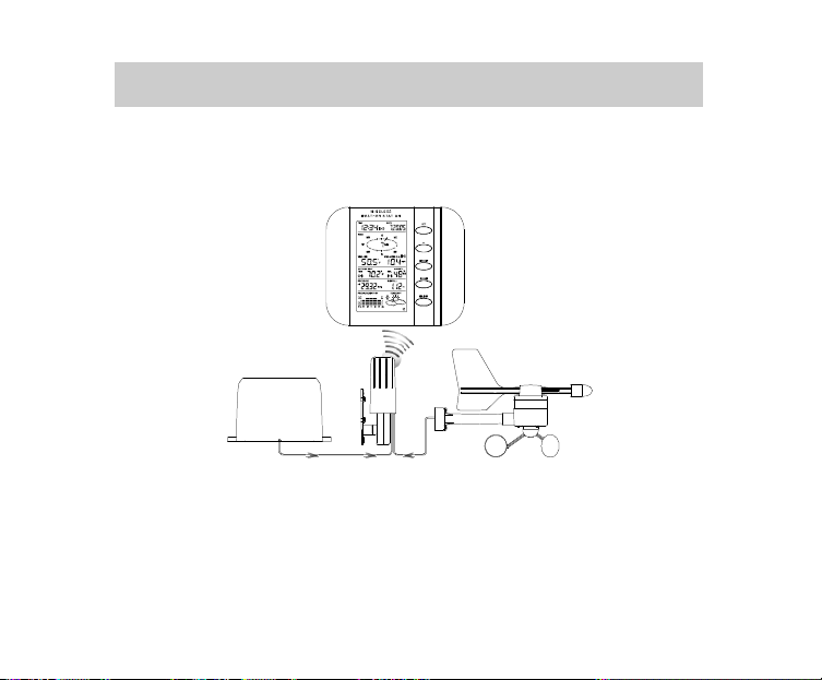
SETTING UP:
Cable connection between
Cable connection between
W
ireless transmission at
hygro
to the Weather
Center
Rain sensor
915 MHz - thermo-
Note:
When putting the Weather Center into operation, it is important to perform in close
proximity (e.g. on a table) a complete wiring and set-up of the system. This step is
sensor
Weather Center
Wind sensor
the rain sensor and the
thermo-hygro sensor
the wind sensor and the
thermo-hygro sensor
6
important to test all components for correct function before placing and mounting
them at their final destinations (See Positioning below)
1. Unwind the cables of the Rain and the Wind sensors. Connect the Rain and
the Wind sensors to the Thermo-hygro sensor by plugging the connector heads
of the two sensors into the appropriate sockets of the Thermo-hygro sensor.
Sockets for wind
and rain sensor
2. First insert the batteries into the Thermo-hygro sensor (see “How to install
and replace the batteries into the Thermo-hygro sensor“ below).
3. Then insert the batteries into the W eather Center (see “How to install and
replace the batteries into the Weather Center” below). Once the batteries
are installed, all segments of the LCD will light up briefly and a short signal
tone will be heard. It will then display the time as 12:00, the date as 1.1.05, the
weather icons, and air pressure value. "- - -" will be shown for outdoor data.
4. Afterwards, the Weather Center will start receiving data from the transmitter.
The outdoor temperature, humidity wind chill and wind speed should then be
7

displayed on the Weather Center. If this does not happen after 30 seconds, the
batteries will need to be removed from both units. You will have to start again
from step 1.
5. You may then check all cables for correct connection and all components for
correct function by manually turning the wind-gauge, moving the weather-vane,
tilting the rain sensor to hear the impact of the internally moving seesaw, etc
(See Positioning below).
6. Time and date shall be manually set (See Manual Setting below).
7. After the Weather Center has been checked for correct function with regard to
the above points and found fit, the initial set up of the weather station system is
finished and the mounting of the system components can take place. It must be
ensured however that all components work properly together at their chosen
mounting or standing locations. If e.g. there appear to be problems with the
915 MHz radio transmission, they can mostly be overcome by slightly changing
the mounting locations.
Note:
The radio communication between the receiver and the transmitter in the open field
reaches distances of max 330 feet, provided there are no interfering obstacles such
as buildings, trees, vehicles, high voltage lines, etc.
8. Radio interferences created by PC screens, radios or TV sets can in some
cases entirely cut off radio communication. Please take this into consideration
when choosing standing or mounting locations.
8

Note :
•
After batteries are installed in the transmitter, install the batteries in the weather
center to receive the signal from the transmitter as soon as possible. If the
weather center is powered more than 5 hours after the transmitter is powered,
the weather center will never receive signal successfully from this transmitter.
In this case, user will need to reinstall the batteries from the transmitter to redo
set-up procedure.
•
After batteries are installed, there will be synchronization between weather
center and the transmitter. At this time, the signal reception icon will be
blinking. When the signal is successfully received by the weather center, the
icon will be switched on. (If it is not successful, the icon will not be shown in
LCD) So the user can easily see whether the last reception was successful
(icon on) or not (icon off). On the other hand, the short blinking of the icon
shows that a reception is in progress.
Transmitter signal
reception icon
•
If the signal reception is not successful on the first frequency (915MHz) for 14
seconds, the frequency is changed to 920MHz and the learning is tried another
9

14 seconds. If still not successful the reception is tried for 14 seconds on
910MHz. This will also be done for re-synchronization.
HOW TO INSTALL AND REPLACE THE BATTERIES INTO THE WEATHER
CENTER
The Weather Center works with 3 x AA, IEC LR6, 1.5V batteries. When the batteries
need to be replaced, the low battery symbol will appear on the LCD.
To install and replace the batteries, please follow the steps below:
1. Remove the battery compartment
cover.
2. Insert the batteries observing the
correct polarity (see the marking in
the battery compartment).
3. Replace the battery cover.
HOW TO INSTALL AND REPLACE THE BATTERIES INTO THE THERMO-HYGRO
SENSOR
The outdoor Thermo-hygro sensor works with 2 x “AA”, IEC LR6 1.5V batteries. To
install and replace the batteries, please follow the steps below:
10

1. Uninstall the rain cover of the transmitter.
2. Remover the battery compartment cover.
3. Insert the batteries, observing the correct polarity (see
the marking in the battery compartment).
4. Replace the battery cover and the rain cover onto the
unit.
Note:
In the event of changing batteries in any of the units, all units need to be reset by
following the setting up procedures. This is because a random security code is
assigned by the thermo-hygro sensor at start-up and this code must be received and
stored by the Weather Center in the first 30 seconds of power being supplied to it.
BATTERY CHANGE:
It is recommended to replace the batteries in all units every 24 months to ensure
optimum accuracy of these units.
Please participate in the preservation of the environment. Return
used batteries to an authorized depot.
11
Note:
The stored History record will not be kept after the battery change is done on the
Weather Center.
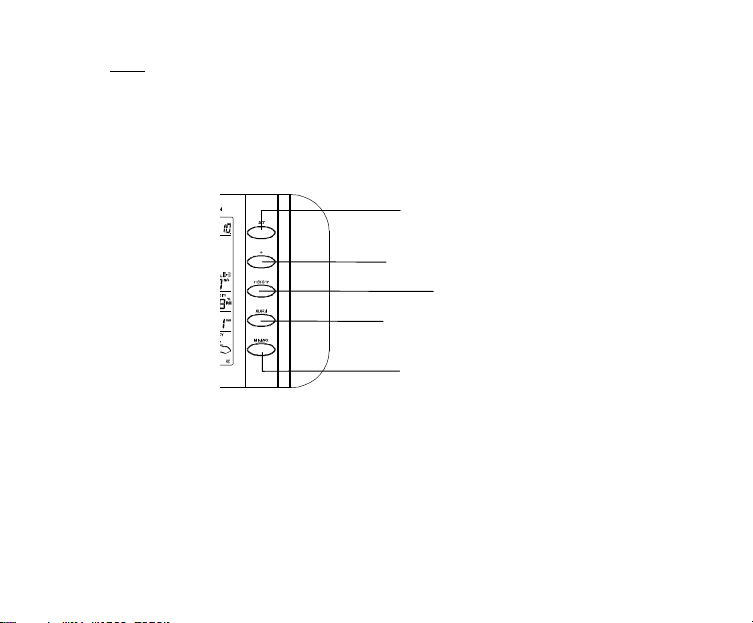
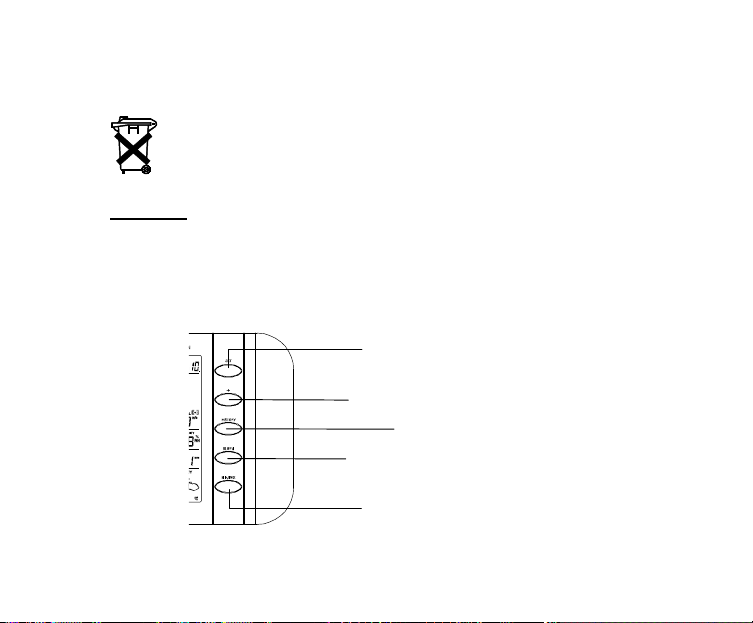
FUNCTION KEYS:
Weather Center:
The Weather Center has 5 easy-to-use function keys.
SET key
•
Press to enter manual setting modes: LCD contrast, Manual time setting, 12/24
hour time display, Calendar setting, ºF/ºC temperature unit, Wind speed unit,
Rainfall unit, Pressure unit, Relative pressure reference setting, Weather
Set key
+ key
HISTORY key
ALARM key
MIN/MAX key
12

Tendency Sensitivity Value setting, Storm warning sensitivity setting and Storm
Alarm On/Off setting
•
In normal display mode, press and hold to switch on/off the Buzzer
•
In the weather alarm setting mode, press and hold to adjust different alarm
value and switch the alarm On/Off
•
Press to activate the reset mode when max or min record is shown
•
Stop the alarm during the time alarm or weather alarm ringing
+ key
•
Press to change the calendar display to the preset alarm time, date, weekday +
date or seconds in the time display
•
Press to adjust (increase) the level of different settings
•
Stop the alarm during the time alarm or weather alarm ringing
•
Press to confirm to reset the max/min record
HISTORY key
•
Press to display the weather data history records
•
Stop the alarm during the time alarm or weather alarm ringing
•
Press to exit manual setting mode and alarm setting mode
ALARM key
•
Press to enter the time alarm and weather alarm setting mode
•
Confirm particular alarm setting
•
Press to exit the manual setting mode
•
Stop the alarm during the time alarm or weather alarm ringing
•
Press to exit max/ min record display mode
13

MIN/MAX key
•
Press to display minimum and maximum records of various weather data
•
Press to adjust (decrease) the level of different settings
•
Stop the alarm during the time alarm or weather alarm ringing
LCD SCREEN
The LCD screen is split into 5 sections displaying the following information:
1. Time and date
2. W ind data
3. Outdoor temperature and humidity,
4. Air pressure and Rainfall data
5. Air pressure history and Weather forecast.
14

temperature
Wind direction display and
wind
essure
Relative air pressure
hPa
C
Outdoor temp.
icon
Transmitter low battery
indicator
TX
display in inHg or
Time display
Wind Chill in °F or °
Outdoor
in °F or ºC
alarm
Air pr
histogram
Low battery
indicator
Time alarm icon
15
Calendar display
Buzzer off indicator
speed in Beaufort
scale
Wind speed Hi/ Lo alarm
icon
Wind speed in mph, km/h
or m/s
Outdoor relative
humidity in %
Outdoor Humidity
alarm icon
Total rainfall in inch or mm
Weather tendency
indicator
Weather forecast
icon
Transmitter signal
reception icon

MANUAL SETTING:
The following manual settings can be changed once the SET key is pressed:
•
LCD contrast setting
•
Manual time setting
•
12/24 hour time display
•
Calendar setting
•
°F/ °C temperature unit setting
•
Wind speed unit
•
Rainfall unit setting
•
Air pressure unit setting
•
Relative pressure reference value setting
•
Weather Tendency Sensitivity value
•
Storm warning threshold value
•
Alarm On/ Off setting
LCD CONTRAST SETTING
The LCD contrast can be set within 8 levels, from "LCD 1" to "LCD8" (default setting is
LCD 5):
1. Press the SET key, the contrast level digit will start flashing.
2. Use the + or MIN/MAX key to adjust the level of contrast.
3. Confirm with the SET key and enter the MANUAL TIME SETTING.
Digit flashing
16

MANUAL TIME SETTING:
Hour
You then may manually set the time of the clock by following the steps below:
Minutes flashing
flashing
1. The hour digit will start flashing.
2. Use the + or MIN/MAX key to set the hour.
3. Press the SET key to switch to the minutes. The minute digit will start flashing.
4. Use the + or MIN/MAX key to set the minute.
5. Confirm the time with the SET key and enter the 12/24 HOUR TIME DISPLAY
SETTING.
12/24 HOUR TIME DISPLAY SETTING:
Digit flashing
The time can be set to view as 12-hour or 24-hour format. The default time display
mode is 12-h. To set to 24-h time display:
1. Use the + or MIN/MAX key to toggle the value.
17

play)
display)
2. Confirm with the SET key and enter the CALENDAR SETTING.
CALENDAR SETTING:
"Date. Month." (for 24h time dis
"Month. Date." (for 12h time
Year
The date default of the Weather Center is 1. 1. of year 2005. The date can be set
manually by proceeding as follows.
1. The year digit starts flashing.
2. Use the + or MIN/MAX key to set the year. The range runs from "00" (2000) to
"99" (2099).
3. Press the SET key to confirm the year and enter the month setting. The month
digit will start flashing.
4. Use the + or MIN/MAX key to set the month.
5. Press the SET key to confirm the month and enter the date setting mode. The
date digit will start flashing.
6. Use the + or MIN/MAX key to set the date.
7. Confirm all calendar settings with the SET key and enter the °F/°C
TEMPERATURE UNIT SETTING.
18

°F/°C TEMPERATURE UNIT SETTING
Flashing
The temperature display can be selected to show temperature data in °F or °C.
(default °F)
1. The temperature unit is flashing
2. Use the + or MIN/MAX key to toggle between “°F” or “°C”.
Confirm with the SET key and enter the WIND SPEED UNIT SETTING
WIND SPEED UNIT SETTING
Flashing
The wind speed unit can be set as mph (mile per hour), km/h (kilometer per hour), or
m/s (meter per second). The default unit is mph.
1. Use the + or MIN/MAX key to toggle between the unit “mph”, “km/h” or “m/s”
2. Confirm with the SET key and enter the RAINFALL UNIT SETTING.
19
RAINFALL UNIT SETTING
Flashing
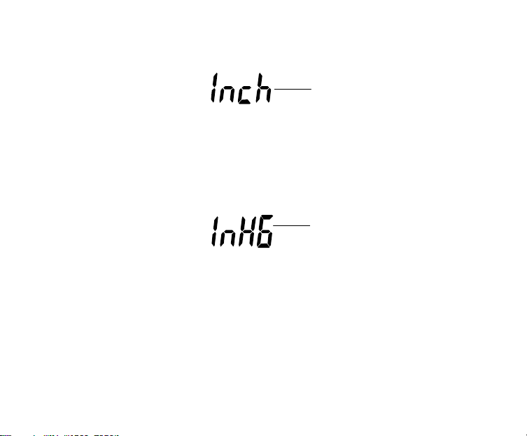
The total rainfall unit can be set as inch or mm. The default unit is inch.
1. Use the + or MIN/MAX key to toggle between the unit “inch” or “mm”
2. Confirm the unit with the SET key and enter the RELATIVE AIR PRESSURE
UNIT SETTING
RELATIVE AIR PRESSURE UNIT SETTING
Flashing
The relative air pressure can be set as inHg or hPa. The default unit is inHg.
1. Use the + or MIN/MAX key to toggle between the unit “inHg" or “hPa”
2. Confirm the unit with the SET key and enter the RELATIVE PRESSURE
REFERENCE VALUE SETTING.
20

RELATIVE PRESSURE REFERENCE VALUE SETTING
Note:
The default reference pressure value of the barometer is 29.91inHg when batteries
are first inserted. For an exact measurement, it is necessary to first adjust the
barometer to your local relative air pressure (related to elevation above sea
level). Ask for the current atmospheric pressure of your home area (Local weather
service, www, optician, calibrated instruments in public buildings, airport).
The relative air pressure can be manually set to another value within the range of
27.17 to 31.90 inHg (919 to 1080 hPa) for a better reference.
Flashing
1. The current relative pressure value will start flashing
2. Use the + or MIN/MAX key to increase or decrease the value. Continually
holding the key will allow the value to increase faster.
3. Confirm with the SET key and enter the WEATHER TENDENCY SENSITIVITY
VALUE SETTING.
21
Note:
Flashing
This feature is useful for those who live at elevations above sea level, but want their
air pressure display to be based on sea level elevation.
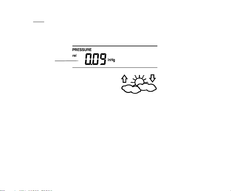
WEATHER TENDENCY SENSITIVITY LEVEL SETTING
You may select a definite switching sensitivity value, .06, .09, or .12 inHg for the
change in the display of weather icons. This represents the "sensitivity" of the weather
forecast (the smaller the value selected, the more sensitive the weather forecast).
The default value is 0.09 inHg.
1. The sensitivity value will start flashing
2. Use the + or MIN/MAX key to select the value.
3. Confirm with the SET key and enter the STORM WARNING SENSITIVITY
SETTING.
22
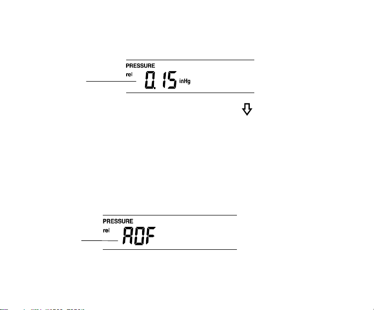
STORM WARNING THRESHOLD VALUE SETTING
Flashing
You may also define a switching sensitivity value for the Storm warning display at a
decrease of air pressure from .09 inHg to .27 inHg over 6 hours (Default 0.15 inHg).
1. The sensitivity value will start flashing.
2. Use the + or MIN/MAX key to select the value.
3. Confirm with the SET key and enter the STORM ALARM ON/OFF SETTING.
STORM ALARM ON/ OFF SETTING
You may also choose to switch On or Off the acoustic Storm warning alarm (Default
OFF).
1. The digit "AOF" will start flashing.
2. Use the + key to switch On or Off the alarm. ("AOF" = OFF; "AON" = On)
3. Confirm with the SET key and the normal display mode will be shown.
Flashing
23
Note:
In case a storm warning alarm is activated, the downward weather tendency arrow will
be flashing. (Also see WEATHER TENDENCY INDICATOR below)
TO EXIT THE MANUAL SETTING MODE
To exit the manual setting anytime during the manual setting modes, press the
ALARM key (or HISTORY key) or wait for the automatic timeout. The mode will return
to the normal time display.
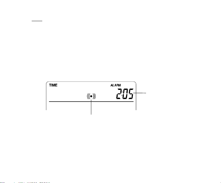
TIME ALARM SETTING
The alarm time can be set by the use of the ALARM and SET key.
1. Press the ALARM key once. The “ALARM” icon and time digits are shown at the
top right of the LCD.
Alarm-On icon
2. Press and hold the SET key for about 2 seconds. The hour digit of the alarm
time will start flashing. Press the + or MIN/MAX key to set the hour of the alarm
time.
3. Press the SET key to confirm and advance to the minute setting. The minute
digit will be flashing.
Alarm time
digit
24

4. Press the + or MIN/MAX key to set the minute of the alarm time. Press the
ALARM key to confirm. Wait for about 30 seconds and the display will return to
normal display mode automatically.
5. In the normal display mode, press the ALARM once key to go to the time alarm
setting mode again. Then press shortly the SET key to switch on or off the time
alarm. (The showing of the icon ((())) means that the time alarm is switched on.)
6. Press the HISTORY key or wait for about 30 seconds and the display will return
to normal display mode automatically.
Note:
The alarm ringing duration is 2 minutes. To stop the alarm, press any key during the
alarm ringing.
WEATHER ALARM OPERATIONS
The Weather alarms can be set when certain weather conditions are met according to
your requirements. For example, you can set the thresholds for the outdoor
temperature to +104°F (high) and 14°F (low), while only enabling the high alarm and
disabling the low alarm (i.e. temperatures <14°F won’t trigger alarm, but temperatures
>+104°F will).
25

Outdoor temp
On icon
Alarm-
High wind
speed AlarmOn icon
Outdoor humidity
Alarm-On icon
The Weather Center can be set to alert when a specific weather condition is reached.
The following Weather Alarm settings can be adjusted in the ALARM setting
mode.
•
High outdoor temperature alarm
•
Low outdoor temperature alarm
•
High outdoor humidity alarm
•
Low outdoor humidity alarm
•
High wind speed alarm
26

Default alarm values:
igh alarm
icon
On
Temperature
Low
High
32°F
104°F
Low 45% Relative
Humidity
High 70%
Wind speed High 62.0mph
HIGH AND LOW OUTDOOR TEMPERATURE ALARM SETTING
Note:
The High and Low outdoor temperature alarm can be set On/Off independently,
according to your needs.
Set the Outdoor temperature alarm value (High or Low alarm value) :
1. In the normal display mode, press the ALARM key twice. The High Outdoor
Temperature alarm display will be shown.
H
Alarm-
icon
27

2. Press and hold the SET key for about 2 seconds. The temperature digit will
start flashing. Press the + or MIN/MAX key to set the high outdoor temp alarm
value. (Keep holding the key will allow the value to increase faster.)
3. Press the ALARM key to confirm the setting. The digit will stop flashing. Press
the SET key to switch on or off the alarm. (The showing of the icon ((()))
means that the alarm is switched on.)
4. Press the ALARM key once. The Low Outdoor Temperature alarm display will
be shown.
5. Press and hold the SET key for about 2 seconds. The temperature digit will
start flashing. Press the + or MIN/MAX key to set the low outdoor temp alarm
value. (Keep holding the key will allow the value to increase faster.)
6. Press the ALARM key to confirm the setting. The digit will stop flashing. Press
the SET key to switch on or off the alarm. (The showing of the icon ((()))
means that the alarm is switched on.)
7. Press the HISTORY key or wait for about 30 seconds and the display will
return to normal display mode automatically.
In case the temperature value meets the condition for high alarm or low alarm, the
value will be blinking, along with the corresponding icon ("HI AL"/ "LO AL").
And the buzzer will ring for 2 minutes. User then may press any key to stop the ring.
User may quit the alarm setting and return to the normal display mode by pressing the
HISTORY key.
28
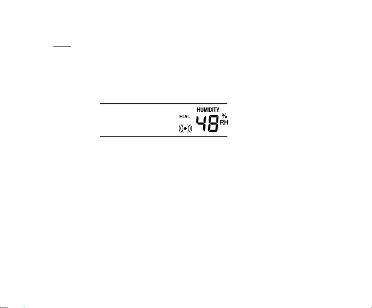
HIGH AND LOW OUTDOOR HUMIDITY ALARM SETTING
Note:
The High and Low outdoor humidity alarm can be set On/Off independently according
to your needs.
Set the Outdoor temperature alarm value (High or Low alarm value):
1. In the normal display mode, press the ALARM key 4 times. The High Outdoor
Humidity alarm display will be shown.
2. Press and hold the SET key for about 2 seconds. The humidity digit will start
flashing. Press the + or MIN/MAX key to set the high outdoor humidity alarm
value.
3. Press the ALARM key to confirm the setting. The digit will stop flashing. Press
the SET key to switch on or off the alarm. (The showing of the icon ((()))
means that the alarm is switched on.)
4. Press the ALARM key once. The Low Outdoor humidity alarm display will be
shown.
5. Press and hold the SET key for about 2 seconds. The humidity digit will start
flashing. Press the + or MIN/MAX key to set the low outdoor humidity alarm
value.
29

6. Press the ALARM key to confirm the setting. The digit will stop flashing. Press
the SET key to switch on or off the alarm. (The showing of the icon ((()))
means that the alarm is switched on.)
7. Press the HISTORY key or wait for about 30 seconds and the display will
return to normal display mode automatically.
In case the humidity value meets the condition for high alarm or low alarm, the value
will be blinking, along with the corresponding icon ("HI AL"/ "LO AL"). And the buzzer
will ring for 2 minutes. User may press any key to stop the sound.
WIND SPEED ALARM SETTING
The High wind speed alarm can be set by following the steps below.
1. In the normal display mode, press the ALARM key six times. The High wind
speed alarm display will be shown.
2. Press and hold the SET key for about 2 seconds. The wind speed digit will start
flashing. Press the + or MIN/MAX key to set the high wind speed alarm value.
3. Press the ALARM key to confirm the setting. The digit will stop flashing. Press
the SET key to switch on or off the alarm. (The showing of the icon ((()))
means that the alarm is switched on.)
30

4. Press the ALARM key once to return to the normal display mode.
In case the wind speed exceeds the condition for high wind speed alarm, the value
will be flashing, along with the corresponding high alarm icon ("HI AL"). And the
buzzer will ring for 2 minutes. User may press any key to stop the sound.
HYSTERESIS
To compensate for fluctuation of the measured data, which may cause the weather
alarm to sound constantly if the measured reading is close to your set level, a
hysteresis function has been implemented for each weather alarm. For example, if the
high temperature alarm is set to +77°F and the current value moves to +77°F, the
alarm will be activated (if it has been enabled). Now when the temperature drops to
+76.8°F or below and thereafter again increases to beyond +77°F, the data will be
blinking, but no alarm will be activated. It has to drop to below +75.2°F (with a pre-set
hysteresis of 1.8°F) so that the alarm can be produced again. Hysteresis values for
the various weather data types are given in the following table:
Weather data Hysteresis
Temperature 1.8°F
Humidity 3% RH
Wind speed 3.1 mph
Note:
The temperature or humidity data will keep on flashing even after a key has been
pressed to stop the alarm or buzzer has been switched off, to indicate that the current
weather condition is out of the pre-set limit(s)
31

WEATHER FORECAST AND WEATHER TENDENCY
Cloudy with sunny
WEATHER FORECASTING ICONS:
Weather forecasting icons is displayed in any of the following combinations at the
right bottom part of LCD:
TENDENCY
Sunny
For every sudden or significant change in the air pressure, the weather icons will
update accordingly to represent the change in weather.
(Every time a new average pressure value has been obtained (once per minute), this
value is compared with an internal reference value. If the difference between these
values is bigger than the selected weather tendency sensitivity, the weather-icon
changes, either for worse or for better. In this case, the current pressure value
becomes the new weather tendency reference.)
If the icons do not change, either the air pressure has not changed or the change has
been too small for the Weather Center to register. So you may adjust the "sensitivity"
of the pressure change checking in the setting mode –see WEATHER TENDENCY
SENSITIVITY VALUE SETTING above.
TENDENCY
intervals
TENDENCY
Rainy
32

However, if the icon displayed is a sun or raining cloud, there will be no change of
icon if the weather gets any better (with sunny icon) or worse (with rainy icon) since
the icons are already at their extremes.
The icons displayed forecasts the weather in terms of getting better or worse and not
necessarily sunny or rainy as each icon indicates. For example, if the current weather
is cloudy and the rainy icon is displayed, it does not mean that the product is faulty
because it is not raining. It simply means that the air pressure has dropped and the
weather is expected to get worse but not necessarily rainy.
Note:
After setting up, readings for weather forecasts should be disregarded for the next 1224 hours. This will allow sufficient time for the Weather station to collect air pressure
data at a constant altitude and therefore result in a more accurate forecast.
Common to weather forecasting, absolute accuracy cannot be guaranteed. The
weather forecasting feature is estimated to have an accuracy level of about 75% due
to the varying areas the Weather Center has been designed for use. In areas that
experience sudden changes in weather (for example from sunny to rain), the Weather
Center will be more accurate compared to use in areas where the weather is stagnant
most of the time (for example mostly sunny).
If the Weather Center is moved to another location significantly higher or lower than
its initial standing point (for example from the ground floor to the upper floors of a
house), discard the weather forecast for the next 48-60 hours, as the Weather Center
may mistake the new location as being a possible change in air-pressure when really
it is due to the slight change of altitude.
33

WEATHER TENDENCY INDICATOR
Working together with the weather icons is the weather tendency indicators (arrow
located on the left and right sides of the weather icons). When the indicator points
upwards, it means that the air-pressure is increasing and the weather is expected to
improve, but when indicator points downwards, the air-pressure is dropping and the
weather is expected to become worse.
Taking this into account, one can see how the weather has changed and is expected
to change. For example, if the indicator is pointing downwards together with cloud and
sun icons, then the last noticeable change in the weather was when it was sunny (the
sun icon only). Therefore, the next change in the weather will be cloud with rain icons
since the indicator is pointing downwards.
Note:
Once the weather tendency indicator has registered a change in air pressure, it will
remain permanently visualized on the LCD.
AIR PRESSURE HISTORY (ELECTRONIC BAROMETER WITH BAROMETRIC
PRESSURE TREND)
The bottom section of the LCD also shows the relative air pressure value and the air
pressure history.
Depending on programming conditions, display of the history of air pressure in form of
a graph consisting of vertical bars.
The bar graph of the electronic barometer shows the air pressure history of the past
12 hours in five 3-hour steps.
34

Air pressure
changes in inHg
Air pressure
changes in hPa
The horizontal axis represents the last 12 hours air pressure recording (-12, -9, -6, -3
and 0 hour). The bars are plotted at each of the 5 steps and give the trend over the
recorded period. The scale on the right compares the result. The "0" in the middle of
this scale determines the current air pressure.
The vertical axis represents the air pressure changes in inHg (+0.12, +0.06, 0, -0.06, -
0.12. The “0” represents the current air pressure). The newly measured pressure was
compared to the previously recorded pressure reading. The pressure change
is expressed by the difference between the current ("0h") and the past readings in
division of ±2 hPa or ±0.06 inHg. If the bars are rising it indicates that the weather is
getting better due to an increase in air pressure. If the bars go down it indicates a
drop of the air pressure and the weather is expected to get worse from the present
time "0".
At every full hour the current air pressure is used as a basis for the display of a new
graph bar. The existing graph is then moved one column to the left.
35
Note:
Text showing wind speed in
For accurate barometric pressure trend, the Weather Center should operate at the
same altitude. For example, it should not be moved. Should the unit be moved, for
instance from the ground to the second floor of the house, the readings for the next
12-24 hours shall be discarded.
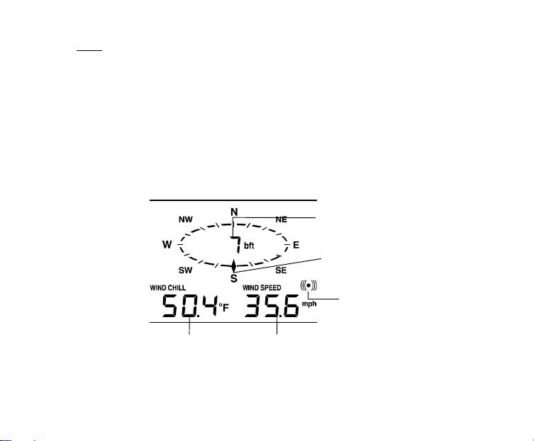
WIND DIRECTION AND WIND SPEED MEASUREMENT
In normal display mode, the second section of the LCD shows the following wind data.
•
•
•
Wind direction (shown on the a compass scale of 16 divisions) and wind speed
in Beaufort scale
Wind chill in °F or °C
Wind Speed in mph, km/h or m/s
Beaufort scale
Pointer indicates the
currently detected wind
direction
This alarm symbol
indicates that the alarm is
set On
Wind chill
Wind speed
36

RAINFALL MEASUREMENT
The total rainfall measurement is displayed in the fourth section of the LCD, in the unit
of mm or inch. (see VIEWING THE MIN/MAX WEATHER DATA below)
VIEWING THE HISTORY DATA
The Weather Center can store up to 200 sets of weather data which are recorded
automatically at 3-hour intervals after the weather station is powered up, at the
nearest time of 0:00, 03:00, 06:00, 09:00, 12:00, 15:00, 18:00 and 21:00. For
instance, if user has manually set the time as 14:52 after installing batteries, the first
history record will be made at the coming 15:00 automatically. Then the second
record will be on 18:00 and so on.
Each weather record includes the W ind direction, Wind speed in Beaufort scale, Wind
chill temperature, wind speed, Outdoor temperature and humidity, relative pressure
and total rainfall, pressure history and weather tendency. Also, the time and date of
recording will be displayed.
Note:
In order to acquire the correct time of recording of the history records, you shall
manually set the current time as soon as installing batteries to the Weather Center.
37

Afterwards, you should avoid changing the pre-set time as it will also alter the
HISTORY icon
recorded "time of recording" of each history record, which may lead to confusion.
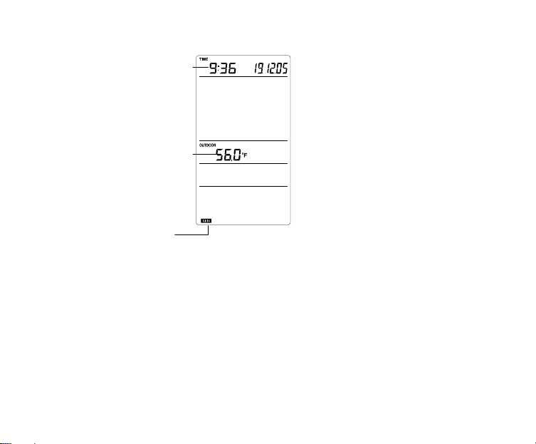
To view the weather history:
1. Press the HISTORY key. The latest weather record will be shown with the date
and time of recording. The "HISTORY" icon will be displayed at the bottom of
the LCD.
38

2. Press MIN/ MAX to view older records.
(Press MIN/MAX and + key to view "Previous" and "Next" record respectively.
The records are made at 3-hour intervals)
Note:
•
The stored history records will not be retained after battery change or whenever
battery is removed.
•
The total rainfall value will be exhibited in whole number (no decimal place) in
the history record.
VIEWING THE MIN/MAX WEATHER DATA
The Weather Center will record the maximum and minimum value of the various
weather data with time and date of recording automatically. The following stored
MIN/MAX weather data can be viewed by pressing the MIN/MAX key in normal
display mode.
39
1. Min outdoor temperature with the date and time of recording
MIN outdoor
temperature
Time and date or
recording
value
2. Max outdoor temperature with the date and time of recording
MIN icon
3. Min outdoor humidity with the date and time of recording
40

4. Max outdoor humidity with the date and time of recording
Time and date or
recording
MAX outdoor
humidity value
MAX icon
41

5. Min Wind chill temperature with the date and time of recording
ind chill
value
Time and date or
recording
MIN w
6. Max Wind chill temperature with the date and time of recording
MIN icon
7. Min Relative pressure with the date and time of recording
42
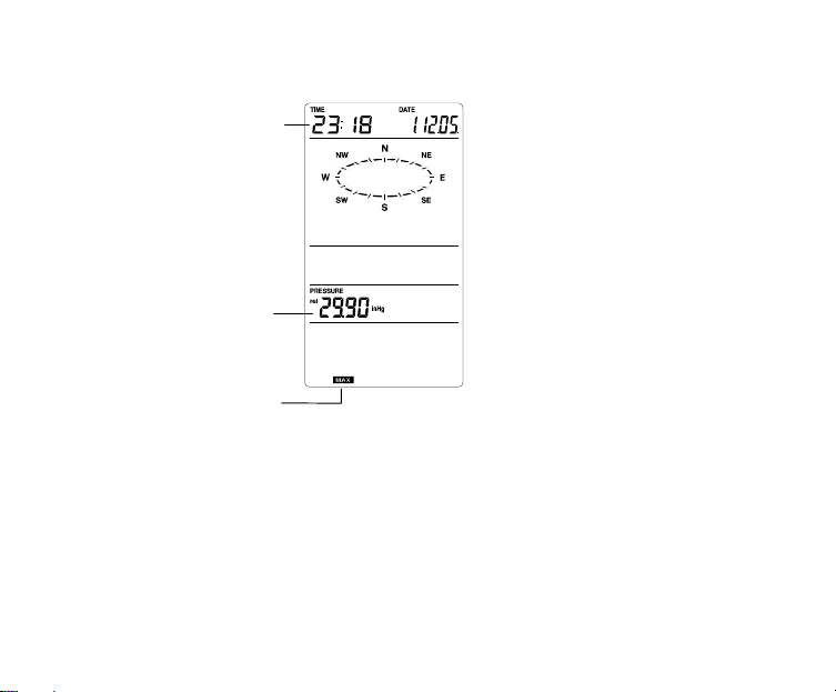
8. Max Relative pressure with the date and time of recording
MAX icon
MAX relative
pressure value
Time and date or
recording
43
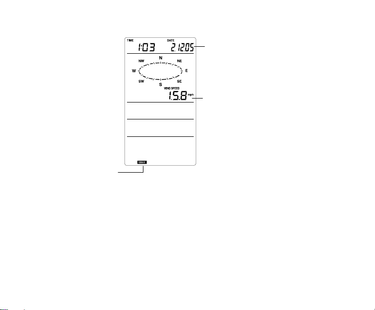
9. Maximum wind speed
Time and date or
recording
MAX wind speed
value
MAX icon
RESET THE MIN/MAX WEATHER DATA
To reset the aforementioned MIN/MAX weather data 1. to 9., you shall need to reset
each of the data independently.
1. Press MIN/MAX key to show the desired weather data. For instance, if you want
to reset the minimum humidity, in the normal display you shall press the
MIN/MAX key 3 times to show the min humidity value.
44

2. Press and hold the SET key for about 2 seconds, then the "RESET" icon will
appear at the bottom part of the LCD.
3. Press the + key once, then the stored value will be reset to the current value and
current time.
4. Press the ALARM key to return to normal display mode.
10. Total rainfall amount
The total rainfall measurement is displayed in the fourth section of the LCD, in the unit
of mm or inch. It shows the total rainfall accumulated since last reset of the Weather
Center.
In normal display mode, press the MIN/MAX key 10 times to show the total rainfall
value. The "RESET" icon will also be shown at the same time.
The total rainfall value is counted
from this time and date
Total rainfall
value
45

To reset the rainfall reading, press the + key once when the Rainfall value and
"Reset" icon is shown. Then the total rainfall amount will be reset to 0, and the time
updated to current time.
Note:
After power up, the time and date and total rainfall is displayed as "- - -". After time is
adjusted manually, the set time will be shown.
SWITCHING ON/OFF THE BUZZER
User may choose to turn off the buzzer so that when the time alarm is switched on
and activated, the buzzer will not sound but we can still see the alarm icon ((()))
flashing on the LCD for time alarm.
On the other hand, when the buzzer is turned off and any weather alarm is activated,
the particular weather digits will flash to show user that the weather condition is being
out of the preset threshold value, yet the buzzer will not sound.
To switch off the buzzer:
1. In normal display mode, press and hold the SET key until the icon "BUZZER
OFF" is shown at the right side above the Wind direction scale. The LCD will
change to setting mode.
2. Press ALARM key once to return to the normal display mode. The "BUZZER
OFF" icon will still be shown.
46
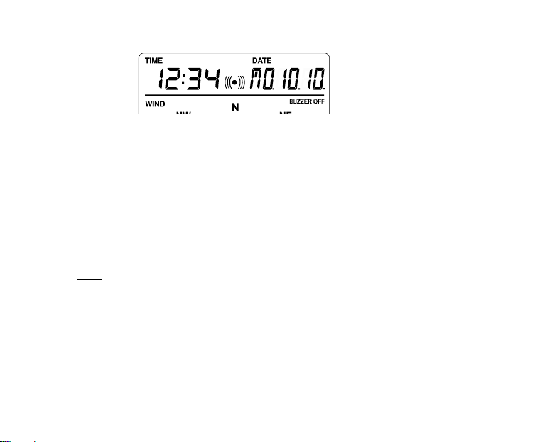
BUZZER OFF icon
To re-enable the buzzer:
1. When the BUZZER OFF icon is shown on LCD, press the SET key shortly and
the BUZZER OFF icon will disappear.
2. Press ALARM key once to return to the normal display mode. The "BUZZER
OFF" icon will no longer be shown. Then the alarm will sound normally.
LOW BATTERY INDICATOR
The low battery indicator of the Weather Center and the Thermo-hygro sensor will be
displayed at the top and bottom portion of the LCD respectively when the battery
power is low. It is recommended to replace the batteries in all units on an annual
basis to ensure optimum accuracy of the system.
Note:
•
After battery change, both the Weather Center and the Thermo-hygro sensor
need to be reset (see note ”Setting up”)
•
The History data record will be clear after the battery change.
47

OUTDOOR TRANSMITTER 915 MHz RECEPTION
The outdoor temperature, humidity, wind data and rainfall are transmitted from the
Thermo-hygro sensor every 4.5 seconds. The Weather Center will then be
synchronized to the Thermo-hygro sensor to receiver outdoor data. The transmission
range (up to 330 feet) of the Outdoor Thermo-hygro sensor may be affected by the
ambient temperature. At cold temperatures the transmitting distance may be
decreased. Please keep this in mind when placing the transmitter.
If the outdoor data are not being received within 30 seconds after setting up (or the
outdoor display shows “- - -“ in the outdoor section of the Weather Center after
consecutive failed attempts during normal operation). Please check the following
points:
1. The distance of the Weather Center or transmitter should be at least 5 to 6.5
feet away from any interfering sources such as computer monitors or TV sets.
2. Avoid positioning the Weather Center onto or in the immediate proximity of
metal doors or window frames.
3. Using other electrical products such as headphones, speakers, or cordless
phones operating on the same signal frequency (915 MHz) may prevent
correct signal transmission and reception.
4. Neighbors using electrical devices operating on the 915 MHz signal frequency
can also cause interference.
5. “Visibility” of Weather Center and Thermo-hygro sensor (e.g. through a
window) increases the range.
Note:
When the 915 MHz signal is received, do not re-open the battery compartment cover
of either the transmitter or Weather Center, as the batteries may spring free from the
48

contacts and force a false reset. Should this happen accidentally then reset all units
(see Setting up above) otherwise transmission problems may occur.
During normal operation, after the outdoor display shows "- - -", the weather station
will change to receive the outdoor data every 15 minutes, until the data is read. Then
the reception period will return to 4.5 seconds.
If no reception is possible despite the observation of these factors, all system units
have to be reset (see Setting up).
POSITIONING
Prior to permanently affixing any of the units, please ensure the following points are
considered:
•
Cable lengths of the units meet with your distance requirements at the point of
fixing
•
Signals from the sensors can be received by the base station at points of
mounting
Weather Center
The Weather Center has been designed to be hung onto wall or free standing with the
2 kinds of foldout stand.
To wall mount
Choose a sheltered place, such as under the eve of a roof. Avoid direct rain and
sunshine.
Before wall mounting, please check that the outdoor temperature and humidity values
can be received from the desired locations. To wall mount:
49

1. Fix a screw (not supplied) into the desired wall, leaving the
Rain Cover
Main Unit
2. Hang the Center onto the screw. Remember to ensure that
Thermo-hygro Sensor
head extended out the by about 5mm.
it locks into place before releasing.
Wall Bracket
50

An ideal mounting place for the Thermo-hygro sensor would be the outer wall beneath
the extension of a roof, as this will protect the sensor from direct sunlight and other
extreme weather conditions.
To wall mount, use the 2 screws to affix the wall bracket to the desired wall, plug in
the Thermo-hygro sensor to the bracket and secure both parts by the use of the
supplied screw and ensure that the cables from the wind and rain sensors are
correctly plugged in otherwise data transmission errors could occur.
Wind Sensor
Wind vane
Vertical
mast
Wind fan
Horizontal
panel
51

Firstly, check that the wind-fan and the wind-vane can rotate freely before fixing the
unit. For correct and accurate readings it is important to mount the sensor so that the
front (marked E) is pointing in East-West direction. The wind sensor should now be
mounted using the screw or cable tie provided onto a solid wall/ panel mast or mast to
allow the wind to travel around the sensor unhindered from all directions (ideal mast
size should be from diameter about
5
/8” to 11/4”).
Once the wind sensor is fixed onto the mast, connect the cable to the corresponding
thermo-hygro sensor socket so that operating power supply can be received and data
can be transmitted to the base station.
Rain Sensor
For best results, the rain sensor should be securely mounted onto a horizontal surface
about 1 meter above the ground and in an open area away from trees or other
coverings where rainfall may be reduced causing inaccurate readings.
When securing into place, check that rain excess will not collect and store at the base
of the unit but can flow out between the base and the mounting surface (test by
pouring clean water).
52

After mounting the rain sensor, connect the cable to the thermo-hygro sensor at the
corresponding socket so power supply can be received and data be transmitted to the
base station
The rain sensor is now operable. For testing purposes, very slowly pour a small
amount of clean water into the rain sensor funnel. The water will act as rainfall and will
be received and displayed at the base station after about 2 minutes delay i.e. when
the reading interval is reached.
CARE AND MAINTENANCE:
•
Extreme temperatures, vibration and shock should be avoided as these may
cause damage to the units and give inaccurate forecasts and readings.
•
When cleaning the display and casings, use a soft damp cloth only. Do not use
solvents or scouring agents as they may mark the LCD and casings.
•
Do not submerge the units in water.
•
Immediately remove all low powered batteries to avoid leakage and damage.
Replace only with new batteries of the recommended type.
•
Do make any repair attempts to the units. Return it to their original point of
purchase for repair by a qualified engineer. Opening and tampering with the
units may invalidate their guarantee.
•
Do not expose the units to extreme and sudden temperature changes, this may
lead to rapid changes in forecasts and readings and thereby reduce their
accuracy.
53

SPECIFICATIONS:
Temperature measuring range:
Outdoor : -40°F to +139.8°F with 0.2°F resolution
-40ºC to +59.9ºC with 0.1ºC resolution
(“OF.L” displayed if outside this range)
Relative humidity measuring range:
Outdoor : 1% to 99% with 1% resolution
(“- -” displayed if < 1%, "99" displayed if ≥ 99%)
Wind speed : 0 to 111.8 mph (0 to 50 m/s)
(displayed "OF.L" when > 50m/s)
Wind chill : -40°F to +139.8°F (-40ºC to +59.9ºC)
(displayed "OF.L" if outside this)
Relative pressure pre-set range : 27.17 to 31.90 inHg (919 to 1080 hPa)
Rainfall : 0" to 393.6" (0 to 9999 mm) (displayed
"OF.L" when > 9999mm)
Outdoor data reception : every 4.5 seconds
Air pressure checking interval : every 15 seconds
Transmission range : up to 330 feet (100meters) in open space
Power:
Weather Center : 3 x AA, IEC LR6, 1.5V
Thermo-hygro sensor : 2 x AA, IEC LR6, 1.5V
Battery life : approximately 24 months (Alkaline batteries
recommended)
54

Dimensions (L x W x H)
Weather Station : 6.51" x 1.21" x 5.58" (165.4 x 30.8 x 141.9 mm)
Thermo-hygro transmitter : 2.25" x 2.44" x 6.18" (57.3 x 62 x 157 mm)
Wind sensor : 9.84" x 6.45" x 7.58" (250 x 164 x 192.7 mm)
Rain sensor : 5.67" x 2.15" x 3.46" (144 x 54.6 x 88 mm)
LIABILITY DISCLAIMER
•
The electrical and electronic wastes contain hazardous substances. Disposal
of electronic waste in wild country and/or in unauthorized grounds strongly
damages the environment.
•
Please contact your local or/and regional authorities to retrieve the addresses
of legal dumping grounds with selective collection.
•
All electronic instruments must from now on be recycled. User shall take an
active part in the reuse, recycling and recovery of the electrical and electronic
waste.
•
The unrestricted disposal of electronic waste may do harm on public health and
the quality of environment.
•
As stated on the gift box and labeled on the product, reading the “User manual”
is highly recommended for the benefit of the user. This product must however
not be thrown in general rubbish collection points.
•
The manufacturer and supplier cannot accept any responsibility for any
incorrect readings and any consequences that occur should an inaccurate
reading take place.
•
This product is designed for use in the home only as indication of the
temperature.
•
This product is not to be used for medical purposes or for public information.
•
The specifications of this product may change without prior notice.
55

•
This product is not a toy. Keep out of the reach of children.
•
No part of this manual may be reproduced without written authorization of the
manufacturer.
WARRANTY
For warranty work, technical support, or information contact:
La Crosse Technology, Ltd
2809 Losey Blvd. South
La Crosse, WI 54601
Phone: 608.782.1610
Fax: 608.796.1020
support@lacrossetechnology.com
sales@lacrossetechnology.com
(information on other products)
www.lacrossetechnology.com
For more information, please visit:
www.lacrossetechnology.com/1610itc
e-mail:
(warranty work)
web:
Springfield / Lacrosse Canada.
1-800-661-6721
5151 Thimens Rd.
Montreal, Quebec
H4R 2C8
56

All rights reserved. This handbook must not be reproduced in any form, even in excerpts, or
duplicated or processed using electronic, mechanical or chemical procedures without written
permission of the publisher.
This handbook may contain mistakes and printing errors. The information in this handbook
is regularly checked and corrections made in the next issue. W e accept no liability for
technical mistakes or printing errors, or their consequences.
All trademarks and patents are acknowledged.
57
STATION MÉTÉO FAMILIALE
WS-1610TWC-IT
Manuel d'Utilisation
58

TABLE DES MATIÈRES
Sujet
Fonctionnalités 61
Installation 65
Touches de fonction 71
Écran LCD 73
Réglage manuel 75
Réglage de l'alarme de réveil 83
Fonctionnement des alarmes météo 85
Hystérésis 90
Prévisions et tendance météo 91
Direction et vitesse du vent 95
Pluviométrie 96
Affichage des données de l'historique 97
Affichage des relevés Minimum / Maximum 99
Activation / Désactivation de la sonnerie 106
Vérification de la réception du signal 915 MHz 107
Positionnement 109
Soin et entretien 113
Caractéristiques techniques 113
In formations sur la garantie 116
Page
59

STATION MÉTÉO FAMILIALE
Manuel d'Utilisation
Nous vous félicitons d'avoir choisi cette station météo alliant design sophistiqué et
technologie innovante en matière de mesures météorologiques. Elle permet d’afficher
l’heure, la date, le calendrier, les prévisions météo, la vitesse et la direction du vent,
la pluviométrie, la température et l’hygrométrie extérieures ainsi que la pression
atmosphérique. D’une grande simplicité d’utilisation, elle permet également de
programmer plusieurs alarmes relatives aux différents relevés météo.
Ce produit vous offre :
INSTANT TRANSMISSION est la
nouvelle technologie de transmission
sans fil de pointe conçue et
développée en exclusivité par LA
CROSSE TECHNOLOGY. INSTANT
TRANSMISSION assure la mise à jour
immédiate (toutes les 4.5 secondes !)
de toutes les données extérieures
relevées par les capteurs : suivez les
variations climatiques en temps réel !
60

FONCTIONNALITÉS :
Écran
Station Météo Familiale
LCD
Touches de
fonction
•
Affichage de l'heure (réglage manuel)
•
Format de l'heure 12/24 H
•
Affichage du calendrier (jour de la semaine, date, mois, année)
•
Fonction réveil
•
Prévision météo par 3 icônes avec flèche de tendance
•
Affichage de la température extérieure en °F ou ºC
•
Affichage de l'hygrométrie extérieure en %RH
Socle rabattable
Encoche pour
fixation murale
Couvercle du
compartiment à
piles
Socle rabattable
61

•
Affichage des relevés Min / Max de température et d'hygrométrie extérieures
avec date et heure des relevés
•
Alarmes haute et basse de température et d’hygrométrie extérieures
•
Pression atmosphérique relative affichée en inHg ou hPa
•
Histogramme de pression atmosphérique sur les 12 dernières heures
•
Sélection du contraste de l'écran LCD
•
Témoin d’usure des piles
•
Affichage de la direction du vent (16 directions)
•
Affichage de la vitesse du vent en mph, km/h ou m/s, et Échelle de Beaufort
•
Affichage du Windchill en °F ou °C
•
Affichage du relevé Max de vitesse du vent avec date et heure du relevé
•
Alarme haute de vitesse du vent
•
Réinitialisation manuelle des données de température/hygrométrie extérieures,
pression atmosphérique et Windchill
•
Affichage de la pluviométrie totale en mm ou inch
•
Alarme de tempête
•
Activation/désactivation du signal sonore
•
Enregistrement dans un historique de 200 jeux de données, relevés toutes les
3 heures justes
•
Transmission à distance par 915 MHz
•
Rayon de transmission jusqu'à 330 ft
62

TRANSMETTEUR THERMO-HYGRO
•
Transmission de la température et de l'hygrométrie extérieures
vers la station météo par fréquence 915 MHz
•
Chapeau protecteur
•
A installer dans un endroit abrité (non exposé directement au
soleil et à la pluie)
ANEMOMETRE
•
Connexion au transmetteur thermo-hygro par
câble
•
A fixer sur une mât ou une surface horizontale
63

PLUVIOMETRE
•
Connexion au transmetteur thermo-hygro par
câble
•
A installer sur une surface horizontale
64

INSTALLATION :
Transmission sans fil par
du
hygro
Pluviomètre
fréquence 915 MHz
transmetteur thermo-
vers la station météo
Connexion par câble du
pluviomètre au
transmetteur
thermo-hygro
Station Météo
Connexion par câble
de l'anémomètre au
transmetteur
thermo-hygro
Anémomètre
65

Remarque :
Afin de vérifier le bon fonctionnement de tous les éléments, il est recommandé de
tester le système à distance rapprochée (par exemple sur une table) en connectant
tous les câbles, avant d'installer les éléments à leurs emplacements définitifs (voir le
paragraphe Positionnement ci-après)
1. Déroulez les câbles du pluviomètre et de l'anémomètre, puis connectez-les au
transmetteur thermo-hygro en branchant les deux fiches dans les prises
appropriées du transmetteur.
Prises de
connexion du
pluviomètre et de
l'anémomètre
2. Commencez par installer les piles dans le transmetteur thermo-hygro (voir
“Comment installer et remplacer les piles dans le transmetteur thermo-
hygro“ ci-dessous).
3. Ensuite, installez les piles dans la station météo (voir “Comment installer et
remplacer les piles dans la station météo” ci-dessous). Une fois les piles
installées, tous les segments de l’écran LCD s’allument brièvement et un court
66

signal sonore se fait entendre. L’appareil affiche ensuite l’heure (12:00), la date
(1.1.05), les icônes météo et la pression atmosphérique. "- - -" s’affichent pour les
données extérieures.
4. La station météo commence ensuite à recevoir les données du transmetteur. La
température et l’humidité extérieures, ainsi que la vitesse et la direction du vent
devraient s’afficher à l’écran. Si cela ne se produit pas dans les 30 secondes,
retirez les piles des deux appareils et recommencez à partir de l’étape 1.
5. Vérifiez ensuite le bon branchement des câbles et le bon fonctionnement de tous
les éléments en tournant manuellement l'hélice et la girouette de l'anémomètre et
en inclinant le pluviomètre afin d’entendre le basculement du mécanisme interne
etc. (voir le paragraphe Positionnement ci-après).
6. Réglez manuellement l'heure et la date (voir le paragraphe Réglage Manuel ci-
après).
7. Lorsque le câblage et le bon fonctionnement des éléments de la station météo
ont été vérifiés avec succès, l'installation initiale est terminée. Les éléments
peuvent alors être installés à leurs emplacements définitifs. Si la transmission
915 MHz ne s’effectue pas correctement, nous vous invitons à déplacer
légèrement les éléments afin de rétablir le signal.
Remarque :
La distance de transmission entre le transmetteur et la station de base est d'environ
330 ft en champ libre, à condition que le signal ne soit pas perturbé par la présence
d'immeubles, d’arbres, de véhicules, de lignes à haute tension, etc.
8. Les interférences radio produites par les écrans d'ordinateur, radios ou
téléviseurs peuvent, dans les cas extrêmes, stopper la communication radio.
Tenez compte de ce facteur lorsque vous choisissez les endroits de fixation.
67

Note :
•
Immédiatement après l’insertion des piles dans le transmetteur, et pour
garantir la bonne transmission, il est conseillé d’insérer les piles dans la station
de base. Dans le cas où les piles sont insérées dans la station de base plus de
5 heures après l’insertion des piles dans le transmetteur, la transmission des
informations ne sera pas possible. Il sera alors nécessaire de réinitialiser
l’ensemble de votre station.
•
Après l’insertion des piles, une phase de synchronisation entre la station de
base et le transmetteur débute. Le signal de réception des données
extérieures clignote alors à l’écran. Lorsque le signal est réceptionné par la
station météo, l’icône reste affichée à l’écran (l’icône ne sera pas affichée si la
réception échoue). L’utilisateur peut ainsi s’assurer de la bonne réception du
signal (icône affichée) ou de l’échec de réception (icône absente). Un signal de
réception qui clignote indique une réception en cours des données extérieures.
Signal de réception des
données extérieures
68

•
Si, dans les 14 secondes, la réception du signal n'est pas réussie sur la
première fréquence (915MHz), la fréquence sera changée en 920MHz et la
recherche du signal s'effectuera à nouveau pendant 14 secondes.
Si la réception n'est toujours pas réussie, la fréquence sera alors changée en
910MHz pendant encore 14 secondes. Ce changement de fréquence se fera
également lors d'une re-synchronisation.
INSTALLATION ET REMPLACEMENT DES PILES DE LA STATION
MÉTÉO
La Station Météo fonctionne avec 3 piles 1,5 V de type AA, IEC LR6. Lorsque les
piles sont usées, le témoin d’usure des piles s'affiche à l'écran LCD. Pour installer ou
remplacer les piles, veuillez suivre les étapes suivantes :
1. Retirez le couvercle du compartiment
à piles.
2. Insérez les piles en respectant la
polarité (voir le marquage à
l'intérieur).
3. Remettez le couvercle.
69

INSTALLATION ET REMPLACEMENT DES PILES DU
TRANSMETTEUR THERMO-HYGRO
Le transmetteur thermo-hygro extérieur fonctionne avec 2 piles 1,5 V de type AA, IEC
LR6, 1.5V. Pour installer ou remplacer les piles, veuillez suivre les étapes suivantes :
Remarque :
Lors du remplacement des piles de l’un ou l’autre des éléments, il est nécessaire de
réinitialiser la station complète en suivant les étapes décrites au paragraphe
Installation. Cette étape est nécessaire en raison du code aléatoire de sécurité
généré par le transmetteur lors de sa mise en fonctionnement, qui doit être reçu et
enregistré par la station météo dans les 30 secondes suivant sa mise sous tension.
1. Retirez le chapeau protecteur du transmetteur.
2. Faites glisser le couvercle du compartiment à piles
3. Insérez les piles en respectant la polarité (voir le
marquage à l'intérieur).
4. Remettez le couvercle du compartiment à piles et le
chapeau protecteur.
70
REMPLACEMENT DES PILES :
Nous vous conseillons de remplacer les piles de tous les éléments bi annuellement
afin de garantir la précision des relevés.
Remarque :
L'historique des données météo sera effacé à chaque remplacement des piles de la
station météo.
TOUCHES DE FONCTION :
Station Météo Familiale :
La Station Météo dispose de cinq touches de fonction simples d’utilisation.
Participez à la protection de l'environnement. Rapportez les piles
usagées à un centre de collecte agréé.
Touche SET
Touche +
Touche HISTORY
Touche ALARM
Touche MIN/MAX
71

Touche SET (Réglage)
•
Appuyer pour accéder aux réglages manuels : contraste de l’écran LCD,
réglage manuel de l’heure, affichage de l’heure au format 12/24 heures, réglage
du calendrier, choix de l’unité de température (ºF/ ºC), de l’unité de vitesse du
vent, de l’unité de mesure des précipitations, réglage de la pression
atmosphérique relative, réglage de la sensibilité des prévisions météo, réglage
du seuil d’alerte de tempête et activation/désactivation de l’alarme de tempête.
•
Maintenir cette touche enfoncée pour activer/désactiver le signal sonore
•
Maintenir cette touche enfoncée pour accéder au réglage d’une Alarme Météo,
puis pour régler les valeurs de l'alarme, l'activer ou la désactiver.
•
Appuyer pour réinitialiser les relevés min/max lorsque ceux-ci sont affichés
•
Appuyer pour stopper la sonnerie du réveil ou de l'alarme météo déclenchée
Touche +
•
Appuyer pour afficher successivement le calendrier, l'heure d’alarme de réveil,
la date, le jour de la semaine ainsi que la date et les secondes à la section
« Heure »
•
Appuyer pour augmenter les valeurs lors des réglages
•
Appuyer pour arrêter la sonnerie du réveil ou de l'alarme météo déclenchée
•
Appuyer pour confirmer la réinitialisation des données min/max.
Touche HISTORY (Historique)
•
Appuyer pour afficher l'historique des données météo
•
Appuyer pour arrêter la sonnerie du réveil ou de l'alarme météo déclenchée
•
Appuyer pour sortir du réglage manuel et du réglage de l’alarme.
72

Touche ALARM (Alarme)
•
Appuyer pour accéder au réglage de l’alarme de réveil et des alarmes météo
•
Appuyer pour confirmer le réglage d'une alarme
•
Appuyer pour sortir du réglage manuel
•
Appuyer pour arrêter la sonnerie du réveil ou de l'alarme météo déclenchée
•
Appuyer pour sortir de l’affichage des données min/max.
Touche MIN/MAX
•
Appuyer pour afficher les relevés minimum et maximum des différentes
données météo
•
Appuyer pour diminuer les valeurs lors des réglages
•
Appuyer pour arrêter la sonnerie du réveil ou de l'alarme météo déclenchée
ÉCRAN LCD
L'écran LCD est divisé en 5 sections affichant les informations suivantes :
1. Heure et date
2. Données anémométriques
3. Température et hygrométrie extérieures
4. Données pluviométriques et de pression atmosphérique
5. Historique de la pression atmosphérique et prévisions météo.
73
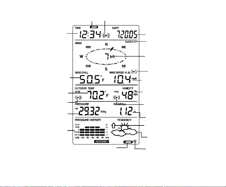
Section Heure
Histogramme de
l'historique de la
pression
Pression
atmosphérique relative
Refroidissement éolien
rme
Icône de l'alarme de la
température extérieure
Témoin d'usure
Témoin de pile de
ure
C
TX
Température extérie
en °F ou °C
en °F ou º
en inHg ou hPa
atmosphérique
des piles
l’émetteur faible
Icône réveil
74
Section Calendrier
Témoin de vibreur
éteint
Direction du vent et
vitesse en Échelle de
Beaufort
Icône de l'alarme de vitesse
du vent Fort/Fible
Vitesse du vent en mph,
km/h ou m/s
Humidité relative
extérieure en %
Icône de l'ala
d'hygrométrie
extérieure
Pluiviométrie totale en
pouces ou mm
Indicateur de
tendance météo
Icône de prévisions
méteo
Icône de réception du
signal de l’émetteur

RÉGLAGE MANUEL :
Appuyez sur la touche SET pour accéder aux réglages manuels suivants :
•
Contraste de l'écran LCD
•
Heure
•
Format d'affichage 12/24 H
•
Calendrier
•
Unités de mesure de la température °F/ °C
•
Unités de mesure de la vitesse du vent
•
Unités de mesure de la pluviométrie
•
Unités de mesure de la pression atmosphérique
•
Valeur de référence de la pression atmosphérique relative
•
Sensibilité de l'indicateur de tendance météo
•
Seuil de déclenchement de l'alarme de tempête
•
Activation/désactivation de l'alarme de tempête
CONTRASTE DE L’ÉCRAN LCD
Vous pouvez choisir huit niveaux de contraste pour l'écran LCD, de "LCD 1" à "LCD
8" (réglage par défaut : LCD 5) :
1. Appuyez sur la touche SET ; le chiffre du niveau de contraste clignote.
2. Modifiez le niveau de contraste à l'aide des touches + ou MIN/MAX.
Chiffre
clignotant
75
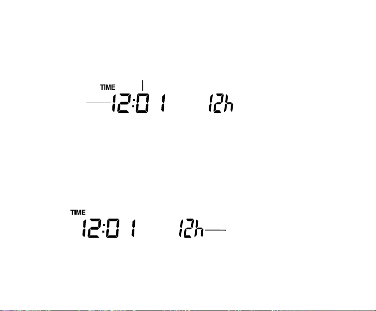
3. Appuyez sur la touche SET pour confirmer et passer au RÉGLAGE MANUEL
Heures
clignotantes
DE L’HEURE
RÉGLAGE MANUEL DE L'HEURE :
Réglez maintenant l'heure en suivant les étapes ci-dessous :
Minutes clignotantes
1. Le chiffre des heures clignote.
2. Modifiez les heures à l'aide des touches + ou MIN/MAX.
3. Appuyez sur SET pour passer au réglage des minutes. Le chiffre des minutes
clignote.
4. Modifiez les minutes à l'aide des touches + ou MIN/MAX.
5. Appuyez sur la touche SET pour confirmer et passer au réglage du FORMAT
12/24 H.
FORMAT 12/24 H :
Chiffre
clignotant
76

Année
(format 24 H)
(format 12 H)
L'heure peut être affichée au format 12 H ou 24 H. Le format par défaut est “12 H”.
Pour basculer au format “12 H” :
1. Appuyez sur la touche + ou MIN/MAX.
2. Appuyez sur la touche SET pour confirmer et passer au réglage du
CALENDRIER.
CALENDRIER :
"Date. Mois."
"Mois. Date."
La date par défaut de la station météo est le 1. 1. de l'année 2005. Pour régler la date
manuellement :
1. Le chiffre de l'année clignote.
2. Modifiez l'année à l'aide des touches + ou MIN/MAX, de "00" (2000) à "99"
(2099).
3. Appuyez sur la touche SET pour confirmer et passer au réglage du mois. Le
chiffre du mois clignote.
4. Modifiez le mois à l'aide des touches + ou MIN/MAX.
5. Appuyez sur la touche SET pour confirmer et passer au réglage de la date. Le
chiffre de la date clignote.
77

6. Modifiez la date à l'aide des touches + ou MIN/MAX.
7. Appuyez sur la touche SET pour confirmer tous les réglages du calendrier et
passer au réglage des UNITÉS DE MESURE DE LA TEMPÉRATURE °F/°C.
UNITÉS DE MESURE DE LA TEMPÉRATURE °F/°C
Clignote
La température peut être affichée soit en °F soit en °C (°F par défaut).
1. Les unités de température clignotent
2. Basculez entre °F et °C à l'aide des touches + ou MIN/MAX
3. Appuyez sur la touche SET pour confirmer et passer au réglage des UNITÉS
DE MESURE DE LA VITESSE DU VENT.
UNITÉS DE MESURE DE LA VITESSE DU VENT
Clignote
La vitesse du vent peut être affichée en mph (mile par heure), km/h (kilomètres par
heure) ou m/s (mètres par seconde). L'unité par défaut est le mph.
78

1. Sélectionnez l'unité de mesure “km/h”, “mph” ou “m/s” à l'aide des touches + ou
MIN/MAX
2. Appuyez sur la touche SET pour confirmer et passer au réglage des UNITÉS
DE MESURE DE LA PLUVIOMÉTRIE.
UNITÉS DE MESURE DE LA PLUVIOMÉTRIE
Clignote
La pluviométrie peut être affichée soit en mm soit en inch (pouces). L'unité par défaut
est le inch.
1. Basculez entre “mm” et “Inch” (pouces) à l'aide des touches + ou MIN/MAX
2. Appuyez sur la touche SET pour confirmer et passer au réglage des UNITÉS
DE MESURE DE LA PRESSION ATMOSPHÉRIQUE.
UNITÉS DE MESURE DE LA PRESSION ATMOSPHÉRIQUE
Clignote
La pression atmosphérique peut être affichée soit en inHg, soit en hPa. L'unité par
défaut est le inHg.
1. Basculez entre “hPa" et “inHg” à l'aide des touches + ou MIN/MAX
79

2. Appuyez sur la touche SET pour confirmer et passer au réglage de la VALEUR
Clignote
DE RÉFÉRENCE DE LA PRESSION ATMOSPHÉRIQUE RELATIVE.
VALEUR DE RÉFÉRENCE DE LA PRESSION ATMOSPHÉRIQUE RELATIVE
Remarque :
La valeur de référence par défaut de la pression atmosphérique relative est 29.91
inHg à la première insertion des piles.
Pour obtenir un relevé exact, il est nécessaire de régler la pression atmosphérique
relative locale (en fonction de l'altitude). La pression atmosphérique locale est
disponible sur demande (service météorologique local, Internet, opticiens, instruments
étalonnés dans les lieux publics, aéroports..).
La pression atmosphérique relative peut être réglée manuellement sur une plage de
27,17 à 31,90 inHg (919 à 1080 hPa) pour une référence plus précise.
1. La valeur de la pression atmosphérique relative clignote
2. Modifiez la valeur à l'aide des touches + ou MIN/MAX. Maintenez enfoncée la
touche pour accélérer le réglage.
80

3. Appuyez sur la touche SET pour confirmer et passer au réglage de la
Clignote
SENSIBILITE DES ICONES MÉTÉO
Remarque :
Ce réglage de pression relative est pratique pour ceux qui vivent en altitude mais qui
souhaitent afficher une pression atmosphérique basée sur la pression au niveau de la
mer.
SENSIBILITE DES ICONES MÉTÉO
Vous pouvez choisir une valeur seuil de changement des icônes météo, de 0.06, 0.09
ou 0.12 inHg. Ce réglage représente la "sensibilité" des prévisions météo (plus la
valeur est faible, plus les prévisions météo seront sensibles). La valeur par défaut est
0.09 inHg.
81
 Loading...