


 Loading...
3Com® Switch 8800 Family
Installation Guide
Switch 8807
Switch 8810
Switch 8814
www.3Com.com
Part No. 10015593, Rev. AB
Published: June, 2007
3Com Corporation
350 Campus Drive
Marlborough, MA
USA 01752-3064
Copyright © 2006-2007, 3Com Corporation. All rights reserved. No part of this documentation may be reproduced in any form or by any means or used to make any derivative work (such as translation, transformation, or adaptation) without written permission from 3Com Corporation.
3Com Corporation reserves the right to revise this documentation and to make changes in content from time to time without obligation on the part of 3Com Corporation to provide notification of such revision or change.
3Com Corporation provides this documentation without warranty, term, or condition of any kind, either implied or expressed, including, but not limited to, the implied warranties, terms or conditions of merchantability, satisfactory quality, and fitness for a particular purpose. 3Com may make improvements or changes in the product(s) and/or the program(s) described in this documentation at any time.
If there is any software on removable media described in this documentation, it is furnished under a license agreement included with the product as a separate document, in the hard copy documentation, or on the removable media in a directory file named LICENSE.TXT or !LICENSE.TXT. If you are unable to locate a copy, please contact 3Com and a copy will be provided to you.
UNITED STATES GOVERNMENT LEGEND
If you are a United States government agency, then this documentation and the software described herein are provided to you subject to the following:
All technical data and computer software are commercial in nature and developed solely at private expense. Software is delivered as “Commercial Computer Software” as defined in DFARS 252.227-7014 (June 1995) or as a “commercial item” as defined in FAR 2.101(a) and as such is provided with only such rights as are provided in 3Com’s standard commercial license for the Software. Technical data is provided with limited rights only as provided in DFAR 252.227-7015 (Nov 1995) or FAR 52.227-14 (June 1987), whichever is applicable. You agree not to remove or deface any portion of any legend provided on any licensed program or documentation contained in, or delivered to you in conjunction with, this User Guide.
Unless otherwise indicated, 3Com registered trademarks are registered in the United States and may or may not be registered in other countries.
3Com and the 3Com logo are registered trademarks of 3Com Corporation.
Cisco is a registered trademark of Cisco Systems, Inc.
Funk RADIUS is a registered trademark of Funk Software, Inc.
Aegis is a registered trademark of Aegis Group PLC.
Intel and Pentium are registered trademarks of Intel Corporation. Microsoft, MS-DOS, Windows, and Windows NT are registered trademarks of Microsoft Corporation. Novell and NetWare are registered trademarks of Novell, Inc. UNIX is a registered trademark in the United States and other countries, licensed exclusively through X/Open Company, Ltd.
IEEE and 802 are registered trademarks of the Institute of Electrical and Electronics Engineers, Inc.
All other company and product names may be trademarks of the respective companies with which they are associated.
ENVIRONMENTAL STATEMENT
It is the policy of 3Com Corporation to be environmentally-friendly in all operations. To uphold our policy, we are committed to:
Establishing environmental performance standards that comply with national legislation and regulations.
Conserving energy, materials and natural resources in all operations.
Reducing the waste generated by all operations. Ensuring that all waste conforms to recognized environmental standards. Maximizing the recyclable and reusable content of all products.
Ensuring that all products can be recycled, reused and disposed of safely.
Ensuring that all products are labelled according to recognized environmental standards.
Improving our environmental record on a continual basis.
End of Life Statement
3Com processes allow for the recovery, reclamation and safe disposal of all end-of-life electronic components.
Regulated Materials Statement
3Com products do not contain any hazardous or ozone-depleting material.

CONTENTS
ABOUT THIS GUIDE
|
Conventions |
5 |
|
|
|
|
|
|
|
|
|
Related Documentation |
6 |
|
|
|
|
|
|||
|
About this Document |
6 |
|
|
|
|
|
|||
1 |
|
|
|
|
|
|
||||
PRODUCT OVERVIEW |
|
|
|
|
|
|||||
|
Preface |
7 |
|
|
|
|
|
|
|
|
|
General Architecture |
10 |
|
|
|
|
|
|||
|
Fabric Modules |
17 |
|
|
|
|
|
|
||
|
System Specifications |
24 |
|
|
|
|
|
|||
|
Software Features |
25 |
|
|
|
|
|
|
||
|
|
|
|
|
|
|||||
2 I/O AND APPLICATION MODULES |
|
|
|
|
||||||
|
Overview |
|
29 |
|
|
|
|
|
|
|
|
3C17511 |
1-port 10GBASE-X (XENPAK) 29 |
|
|
|
|
||||
|
3C17512 |
2-port 10GBASE-X (XFP) Module |
30 |
|
|
|
||||
|
3C17513 |
12-port 1000BASE-X (SFP) Module |
31 |
|
|
|||||
|
3C17514 |
24-port 1000BASE-X (SFP) Module |
32 |
|
|
|||||
|
3C17516 |
24-port 10/100/1000BASE-T Module |
33 |
|
|
|||||
|
3C17525 |
1-port 10GBASE-X Advanced (XENPAK) Module 33 |
||||||||
|
3C17526 |
4-port 10GBASE-X (XFP) Module |
34 |
|
|
|
||||
|
3C17527 |
2-port 10GBASE-X (XFP) Advanced Module |
35 |
|||||||
|
3C17528 |
48port 10/100/1000 BASE-T (RJ-45) Module |
|
36 |
||||||
|
3C17530 |
24-port 1000BASE-X (SFP) Advanced Module |
37 |
|||||||
|
3C17531 |
24-port 10/100/1000BASE-T Advanced Module |
37 |
|||||||
|
3C17532 |
48-port 10/100/1000 BASE-T (RJ-45) Access Module 38 |
||||||||
|
3C17533 |
24-port 1000BASE-X (SFP) IPv6 Module |
39 |
|
||||||
|
3C17534 |
24-port 10/100/1000BASE-T IPv6 Module |
40 |
|
||||||
|
3C17536 |
4-port 10GBASE-X (XFP) QUAD IPv6 Module |
|
40 |
||||||
|
3C17537 |
2-port 10GBASE-X (XFP) IPv6 Module |
41 |
|
|
|||||
|
3C17538 |
48-port 1000BASE-X (SFP) IPv6 Module |
42 |
|
||||||
|
Application Modules |
43 |
|
|
|
|
|
|||
|
Transceivers |
46 |
|
|
|
|
|
|
|
|
|
Switch 8800 Port Densities |
47 |
|
|
|
|
||||
3 |
|
|
|
|
|
|||||
INSTALLATION PREPARATION |
|
|
|
|
||||||
|
Safety Recommendations |
49 |
|
|
|
|
||||
|
Examining Installation Site |
50 |
|
|
|
|||
|
Installation Tools |
52 |
|
|
|
|
|
|
4 |
|
|
|
|
|
|||
SWITCH INSTALLATION |
|
|
|
|
||||
|
Confirming Installation Preparation |
53 |
|
|
||||
|
Installation Flow |
53 |
|
|
|
|
|
|
|
Mounting the Switch in User-Supplied Cabinet |
54 |
||||||
|
Connecting PGND Wire and Power Cord |
59 |
|
|||||
|
Installing Cabling Rack |
64 |
|
|
|
|
||
|
Installing Fan Tray |
64 |
|
|
|
|
|
|
|
Installing PoE Lightning Protection Box |
65 |
|
|||||
|
Installing I/O modules |
66 |
|
|
|
|
||
|
Connecting Interface Cables |
67 |
|
|
|
|||
|
Cable Routing Recommendations |
70 |
|
|
||||
|
Cable Management |
70 |
|
|
|
|
||
|
Verifying the Installation |
73 |
|
|
|
|||
5 |
|
|
|
|
||||
DEBUGGING THE SYSTEM |
|
|
|
|||||
|
Setting up Configuration Environment |
75 |
|
|||||
|
Powering and Booting the Switch |
76 |
|
|
||||
6 |
|
|||||||
SWITCH MONITORING AND MAINTENANCE |
||||||||
|
Monitoring the Switch |
79 |
|
|
|
|
||
|
Hardware Maintenance |
81 |
|
|
|
|
||
|
Upgrading the Software |
86 |
|
|
|
|||
|
Password Loss |
95 |
|
|
|
|
|
|
A |
|
|
||||||
LIGHTNING PROTECTION OF THE SWITCH |
|
|||||||
|
Installing a Lightning Arrester for the AC Power |
97 |
||||||
|
Installing a Lightning Arrester for the Network Port 98 |
|||||||
B |
|
|
|
|||||
3COM NETWORK MANAGEMENT |
|
|
||||||
|
3Com Network Supervisor |
101 |
|
|
|
|||
|
3Com Network Director |
102 |
|
|
|
|||
|
3Com Network Access Manager |
102 |
|
|
||||
|
3Com Enterprise Management Suite 103 |
|
||||||
|
Integration Kit with HP OpenView Network Node Manager 103 |
|||||||

ABOUT THIS GUIDE
|
This guide describes the 3Com® Switch 8800 and how to install hardware, |
||
|
configure and boot software, and maintain software and hardware. This guide |
||
|
also provides troubleshooting and support information for your switch. |
||
|
This guide is intended for Qualified Service personnel who are responsible for |
||
|
configuring, using, and managing the switches. It assumes a working knowledge |
||
|
of local area network (LAN) operations and familiarity with communication |
||
|
protocols that are used to interconnect LANs. |
||
n |
Always download the Release Notes for your product from the 3Com World Wide |
||
|
Web site and check for the latest updates to software and product |
||
|
documentation: |
|
|
|
http://www.3com.com |
|
|
|
|
||
Conventions |
Table 1 lists icon conventions that are used throughout this guide. |
||
|
Table 1 |
Notice Icons |
|
|
|
|
|
|
Icon |
Notice Type |
Description |
n
c
Information note |
Information that describes important features or |
|
instructions. |
Caution |
Information that alerts you to potential loss of data |
|
or potential damage to an application, system, or |
|
device. |
w |
Warning |
Information that alerts you to potential personal |
|
injury. |
Table 2 lists text conventions that are used throughout this guide.
Table 2 Text Conventions
Convention |
Description |
|
|
Screen displays |
This typeface represents information as it appears on the |
|
screen. |
Keyboard key names |
If you must press two or more keys simultaneously, the key |
|
names are linked with a plus sign (+), for example: |
Press Ctrl+Alt+Del
The words “enter” and “type” When you see the word “enter” in this guide, you must type something, and then press Return or Enter. Do not press Return or Enter when an instruction simply says “type.”

6 ABOUT THIS GUIDE
Table 2 Text Conventions
Convention |
Description |
|
|
Words in italics |
Italics are used to: |
|
Emphasize a point. |
|
Denote a new term at the place where it is defined in the |
|
text. |
|
Identify menu names, menu commands, and software |
|
button names. |
|
Examples: |
|
From the Help menu, select Contents. |
|
Click OK. |
Words in bold |
Boldface type is used to highlight command names. For |
|
example, “Use the display user-interface command |
|
to...” |
|
|
Related |
The following manuals offer additional information necessary for managing your |
Documentation |
Switch 8800: |
|
■ Switch 8800 Command Reference Guide — Provides detailed descriptions of |
|
command line interface (CLI) commands, that you require to manage your |
|
Switch 8800. |
|
■ Switch 8800 Configuration Guide— Describes how to configure your Switch |
|
8800 using the supported protocols and CLI commands. |
|
■ Switch 8800 Release Notes — Contains the latest information about your |
|
product. If information in this guide differs from information in the release |
|
notes, use the information in the Release Notes. |
|
These documents are available in Adobe Acrobat Reader Portable Document |
|
Format (PDF) on the 3Com World Wide Web site: |
|
http://www.3com.com/ |
|
|
About this Document |
|
c |
3Com supports only the commands that are described in this document set. You |
|
may encounter commands in the device’s command line interface (CLI) that are |
|
not described in this guide. Any command that you see in the CLI but is not |
|
described in this guide is not supported in this version of the software. |
|
Unsupported commands may result in a loss of data and you enter them at your |
|
own risk. |

PRODUCT OVERVIEW
1
Preface |
The 3Com Switch 8800 Family of Routing Switches (referred to as the Switch 8800 |
|
Family) are intelligent, multi-layer modular LAN switches and are ideal for |
|
enterprise environments where non-stop availability of critical applications and the |
|
highest performance, security, and granular control are required. The Switch 8800 |
|
Family delivers high density Gigabit and 10 Gigabit switching in an integrated |
|
chassis platform. Built-in support for IPv6, MPLS, Power over Ethernet (PoE), and |
|
1.44 Tbps backplane capacity ensures unprecedented investment protection. |
|
Resilient Layer-3 routing, hot-swap modules, and redundant power, along with |
|
sub one-second fabric fail over on the Switch 8800, ensure (24 x 7) availability to |
|
support the most demanding enterprise core and campus environments. |
|
Advanced Quality of Service features such as bandwidth management and packet |
|
classification optimize quality for real-time voice and video applications. Intrusion |
|
prevention security capabilities such as IEEE 802.1X Network Login and Access |
|
Control Lists ensure that only authorized users can access network resources. |
|
The Switch 8800 is focused on delivering functionality towards the higher end of |
|
the large Enterprise, with a 4-port 10 Gigabit Module, high density 48-port |
|
Gigabit Modules, as well as a group of Advanced Modules with support for larger |
|
routing tables and/or MPLS. Power over Ethernet (PoE) is built into all Switch |
|
8800s. |
|
Application modules for the Switch 8800 provide the flexibility to add a firewall, |
|
IPsec encryption, network monitoring with NetFlow, and Layer 2 VPN networking |
|
using Virtual Private LAN Service (VPLS) by simply adding a module to the chassis. |
8 CHAPTER 1: PRODUCT OVERVIEW
Currently, the Switch 8800 Family include the following models:
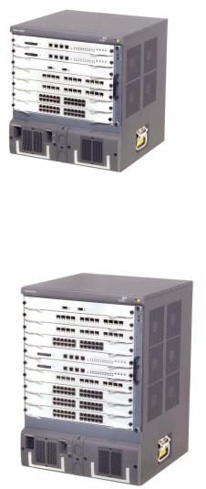
■Switch 8807: This model provides up to 600 Gbps switching capacity. It supports (for example) up to 240 GE ports and 20 x 10GE ports.
Figure 1 3Com Switch 8807 (7-Slot Chassis)
■Switch 8810: This model provides up to 960 Gbps switching capacity. It supports (for example) up to 192 GE ports and 32 x 10GE ports.
Figure 2 3Com Switch 8810 (10-Slot Chassis)

Preface 9
■Switch 8814: This model provides up to 1.44 Tbps switching capacity. It supports (for example) up to 576 GE ports and 48 x 10GE ports.
Figure 3 3Com Switch 8814 (14-Slot Chassis)
10 CHAPTER 1: PRODUCT OVERVIEW
General Architecture The Switch 8800 Family use integrated chassis, which can be subdivided into power area, board area, backplane and fan area.
Chassis and Slots Switch 8807
Figure 4 Switch 8807 slots
|
Fabric |
|
|
|
Fabric |
|
|
|
I/O Module |
Fan |
|
|
I/O Module |
||
|
tray |
||
|
I/O Module |
||
|
|
||
|
I/O Module |
|
|
|
I/O Module |
|
|
AC PSU |
PoE |
AC PSU |
|
Entry |
|||
|
|
■The Switch 8807 chassis provides seven slots in its board area: The top two accommodate fabrics, which can operate in 1+1 redundancy mode; the remaining five accommodate I/O or application modules, which you can select from various available models. All modules in this area are hot-swappable.
■At the bottom of the chassis is the power area that can accommodate one PoE entry module and two PSUs. The two PSUs are online-swappable; they can operate in 1+1 redundancy mode. The switch supports AC power inputs.
■On the right of the chassis is the fan area that contains one vertical hot-swappable fan tray. The fan tray draws and exhausts air from left to right.
General Architecture |
11 |
Switch 8810
Figure 5 Switch 8810 slots
|
I/O Module |
|
|
|
I/O Module |
|
|
|
I/O Module |
|
|
|
I/O Module |
Fan |
|
|
Fabric |
||
|
Fabric |
||
|
tray |
||
|
I/O Module |
||
|
|
||
|
I/O Module |
|
|
|
I/O Module |
|
|
|
I/O Module |
|
|
AC PSU |
PoE |
AC PSU |
|
Entry |
|||
|
|
■The Switch 8810 chassis provides ten slots in its board area: The middle two accommodate fabric modules, which can operate in 1+1 redundancy mode; the remaining eight accommodate I/O or application modules, which you can select from various available models. All modules in this area are hot-swappable.
■At the bottom of the chassis is the power area that can accommodate one PoE entry module and two PSUs. The two PSUs are online-swappable; they can operate in 1+1 redundancy mode. The switch supports AC power inputs.
■On the right of the chassis is the fan area that contains one vertical hot-swappable fan tray. The fan tray draws and exhausts air from left to right.
12 CHAPTER 1: PRODUCT OVERVIEW
Switch 8814
Figure 6 Switch 8814 slots
I/O Module
I/O Module
I/O Module
I/O Module
I/O Module
I/O Module
Fabric
Fabric
I/O Module
I/O Module
I/O Module
I/O Module
I/O Module
I/O Module
PoE
AC PSU AC PSU entry
1 tray Fan
2 tray Fan
■The Switch 8814 chassis provides 14 slots in its board area: The middle two accommodate fabric modules, which can operate in 1+1 redundancy mode; the remaining 12 accommodate I/O or application modules, which you can select from various available models. All modules in this area are hot-swappable.
■At the bottom of the chassis is the power area that can accommodate one PoE entry module and two PSUs. The two PSUs are online-swappable. The switch supports AC power inputs.
■On the right of the chassis is the fan area that contains two vertical hot-swappable fan trays. The fan trays draw and exhaust air from left to right.
Backplane The backplane of the Switch 8800 Family allows high-speed data exchange between fabrics and I/O modules, as well as the exchange of various management and control signals in the system.
Functions
The following are the main functions of the backplane:
■Providing communication channels for signal exchange between boards
■Supporting board hot-swapping
■Supporting auto-discovering boards in slots
■Connecting PSUs, distributing power and providing monitor channels to various components (PSUs, fabrics and I/O modules) in the chassis.
Structure
■ Switch 8807

General Architecture |
13 |
The Switch 8807 uses a passive backplane, which provides five I/O module interfaces, two fabric interfaces, one fan interface, and three -48V power interfaces (two for PSUs and one for PoE entry module).
■ Switch 8810
The Switch 8810 uses a passive backplane, which provides eight I/O module interfaces, two fabric interfaces, one fan interface, and three -48V power interfaces (two for PSUs and one for PoE entry module).
■ Switch 8814
The Switch 8814 uses a passive backplane, which provides 12 I/O module interfaces, two fabric interfaces, two fan interfaces, and three -48V power interfaces (two for PSUs and one for PoE entry module).
AC Power System
n ■ The Switch 8800 Family supports AC power inputs.
■The Switch 8800 Family supports 1+1 power supply redundancy.
■The PSUs of the Switch 8800 Family are online-swappable.
The Switch 8800 Family supports AC power inputs. The power frame is at the bottom of the chassis, with a height of 3U. In the same slot, you can insert an AC PSU. The power frame is in different compartment from the functional board frame and connected to the latter with cables, which are routed along the back of the chassis. The power supply is cooled by built-in fans of the PSUs, which draw air into the chassis from the front and exhaust air out of the chassis from the back.
Table 1 Specifications for AC PSUs
|
Specifications |
|
|
Item |
Switch 8807 |
Switch 8810 |
Switch 8814 |
|
|
|
|
Rated voltage |
100 to 240 VAC, |
100 to 120 VAC, 60 Hz |
100 to 120 VAC, 60 Hz |
range |
50/60 Hz |
200 to 240 VAC, 50 Hz |
200 to 240 VAC, 50 Hz |
|
|
||
Max voltage range |
90 to 264 VAC, 50/60 |
90 to 264 VAC, 50/60 |
90 to 264 VAC, 50/60 |
|
Hz |
Hz |
Hz |
Max input current |
15 A |
15 A |
15 A |
Max output power |
1200 W |
1200 W (90 to 160 V) |
1200 W (90 to 160 V) |
|
|
2000 W (160 to 264 V) |
2000 W (160 to 264 V) |
|
|
|
|
PoE Power Supply The Switch 8800 Family supports Power over Ethernet (PoE). With this feature, a Switch 8800 Family switch equipped with an external PoE power supply and PoE-capable modules can deliver 48 VDC to its remotely powered devices (PDs, such as IP phones, WLAN APs and network cameras) through twisted pairs.
■The Switch 8800 Family can supply power to remote PDs through the Ethernet electrical ports on the I/O modules. Each I/O module can simultaneously supply power to up to 48 PDs with the maximum distance of 100 m (328.1 feet).
■Each Ethernet port can deliver up to 15.4 W to its PD.

14CHAPTER 1: PRODUCT OVERVIEW
■A Switch 8800 supports up to 4500 W (220 V)/2250 W (110 V) power to its PDs. It determines whether to deliver power to a newly detected PD depending on the power it currently supplied.
PoE entry area
The PoE-supported Switch 8807/Switch 8810/Switch 8814 chassis has a PoE entry area between the two power supply units. You can insert a PoE 3C17510 Switch 8800 PoE Entry Module into this area, and connect this module to a 3C17509 Switch 8800 External PoE Power Rack so as to import the output power of the External Power Rack unit.
Figure 7 PoE entry module
External PoE Power Rack (3C17509)
The Switch 8800 External Power Rack is available for the Switch 8807, Switch 8810, and Switch 8814. The External Power Rack has three AC inputs and one DC outputs. Figure 8 shows its front panel.
Figure 8 Front panel of the 3C17509 Switch 8800 External Power Rack PoE power supply
n |
The external PoE power system supports 2+1 redundancy and online-swapping of |
||
|
PSUs. |
|
|
|
To implement the PoE function on the Switch 8800 Family, PoE-capable interface |
||
|
module is required. There are two modules are PoE-capable: |
||
|
■ |
3C17528 |
Switch 8800 48-port 10/100/1000BASE-T |
|
■ |
3C17532 |
Switch 8800 48-port 10/100/1000BASE-T Access |
Both of these I/O Modules are PoE-capable, and will function with the addition of a 3C17529 PoE Option (PoE DIMM Module).

General Architecture |
15 |
Table 2 describes typical equipment configurations and specifications of external PoE power system.
Table 2 Typical equipment configurations and specifications of external PoE power system
Item |
Description |
|
|
Physical dimensions (H x W x D) |
177 x 486 x 320.5 mm (7.0 x 19.1 x 12.6 in.) |
System controller |
One |
Rectifier |
Two NP2500UAC (required) + one redundant |
|
NP2500UAC (optional) |
AC accessory |
Three AC inputs and switches |
|
Three-phase AC voltage detection circuit |
|
Input voltage range: 90 to 290 VAC; rated voltage |
|
and current: 250 VAC, 20 A |
DC accessory |
A single DC output, with max output current of |
|
93 A |
Max power consumption |
4500 W |
|
|
The external PoE power system has monitor function. It provides one system monitoring module, one RS232 and two RS485 monitoring interfaces. The system monitoring module reports the running information of the PSUs in the system to a fabric through RS232 or RS485 interface and indicates alarm status by the alarm LED (ALM). You can connect cables to the interfaces from the front as well as the rear of the frame.
n |
The external PoE power system for the Switch 8800 Family only supports the |
|
RS485 monitoring interface. |
|
Table 3 LEDs of external PoE power system |
|
|
|
Normal |
Abnormal |
|
LED |
Label |
Color |
state |
state |
Abnormal reason |
|
|
|
|
|
|
Input power LED |
AC |
Green |
ON |
OFF |
Loss of AC input power, or blown |
|
|
|
|
|
fuse |
Output power LED |
DC |
Green |
ON |
OFF |
No DC output from PSU |
Fault LED |
Fault |
Red |
OFF |
ON |
Irreversible fault occurred in PSU |
Running status LED |
RUN |
Green |
ON |
OFF |
PSU shutdown or PSU running |
|
|
|
|
|
trouble |
Alarm LED |
ALM |
Red |
OFF |
ON |
Loss of AC input power, |
|
|
|
|
|
under-voltage or over-voltage |
|
|
|
|
|
input, under-voltage or |
|
|
|
|
|
over-voltage output, or PSU fault |
|
|
|
|
|
|
MBUS Introduction
The MBUS is a service-independent maintenance and test bus. No service traffic goes through the MBUS. The shutdown and reset of the MBUS does not affect the services on the switch, and faults that have occurred on modules do not affect the MBUS.
Through the MBUS, the system instructs the MBUS modules on individual cards to power on/off the cards one by one in turn, thus prevent power surging. The MBUS module software must support online upgrade.

16 CHAPTER 1: PRODUCT OVERVIEW
Role and function
The MBUS system is powered by 5 V from the MBUS on the fabric. The 5 V power on the two fabrics are redundant to each other.
Each MBUS module is attached to the MBUS, which contains two control lines:
MBUS0 and MBUS1.
Each card has an independent MBUS module, those on the fabrics are primary
MBUS modules, and those on application modules are secondary MBUS modules.
When the fabrics operate in redundancy mode, the MBUS module on the active fabric is the active module, and the one on the standby fabric is the standby module.
The MBUS uses a controller area network (CAN) bus as its control bus, that uses the 1:1 hot backup and transfers control information at 1 Mbps.
Fan Tray ■ The Switch 8807 uses one 25 W fan tray, which contains four 120 x 120 x 25.4
mm(4.7 x 4.7 x 1.0 in.) axial fan units. The fans can be governed in two modes: fabric-controlled or temperature-controlled. They operate at -48 VDC supplied from the backplane.
■The Switch 8810 uses one 35 W fan tray, which contains six 120 x 120 x 25.4
mm(4.7 x 4.7 x 1.0 in.) axial fan units. The fans can be governed in two modes: fabric-controlled or temperature-controlled. They operate at -48 VDC supplied from the backplane.
■The Switch 8814 uses two 25 W fan trays, each of which contains four 120 x 120 x 25.4 mm (4.7 x 4.7 x 1.0 in.) axial fan units (and totally eight for the two fan trays). The fans can be governed in two modes: fabric-controlled or temperature-controlled. They operate at -48 VDC supplied from the backplane.
Figure 9 Fan tray panel of the Switch 8800 Family

Fabric Modules 17
Table 4 LEDs on fan tray panel
LED |
Color |
Status |
Status |
|
|
|
|
RUN |
Green |
OFF |
The fan tray is faulty. |
|
|
ON |
The fan tray is operating normally. |
ALM |
Red |
OFF |
The fan tray is operating normally. |
|
|
ON |
The fan tray is faulty. |
|
|
|
|
Fabric Modules |
The Switch Fabric serves as the core of the Switch 8800 Family.The following fabric |
|
|
models are available to the Switch 8800 Family: |
|
|
■ 3C17508 - 3Com Switch 8800 360 Gbps Fabric |
|
|
■ 3C17539 - 3Com Switch 8800 720 Gbps Fabric |
|
|
These fabric modules provide: |
|
|
■ Route calculating and forwarding table maintenance. |
|
|
■ Integrating Crossbar switching fabric to accomplish service exchange between |
|
|
different boards. |
|
|
■ System configuration and monitoring functions, which allows the system to |
|
|
monitor other boards and upgrade/reset service board software. |
|
360 Gbps Switch Fabric |
Technical specifications |
|
|
This model applies to the 3C17508. See Table 5 for its specifications. |
|
|
Table 5 360 Gbps Switch Fabric specifications |
|
|
|
|
|
Item |
Specifications |
|
|
|
|
CPU |
MPC755 |
|
Boot ROM |
512 KB |
|
SDRAM |
512 MB (expandable to 1 GB) |
|
Physical dimensions (W x D) 366.7 x 340 mm (14.4 x 13.4 in.) |
|
|
Port |
One Console port, for local configuration management |
|
|
One AUX port, for remote dialup configuration management |
|
|
One 10Base-T/100Base-TX port, for software upgrade and |
|
|
network management |
|
|
One RS232/485 port, for connecting external PoE power frame |
|
|
to provide the PoE function |
|
|
One hot-swap-supported CF port |
|
Max power consumption |
60 W |
|
|
|
Panel
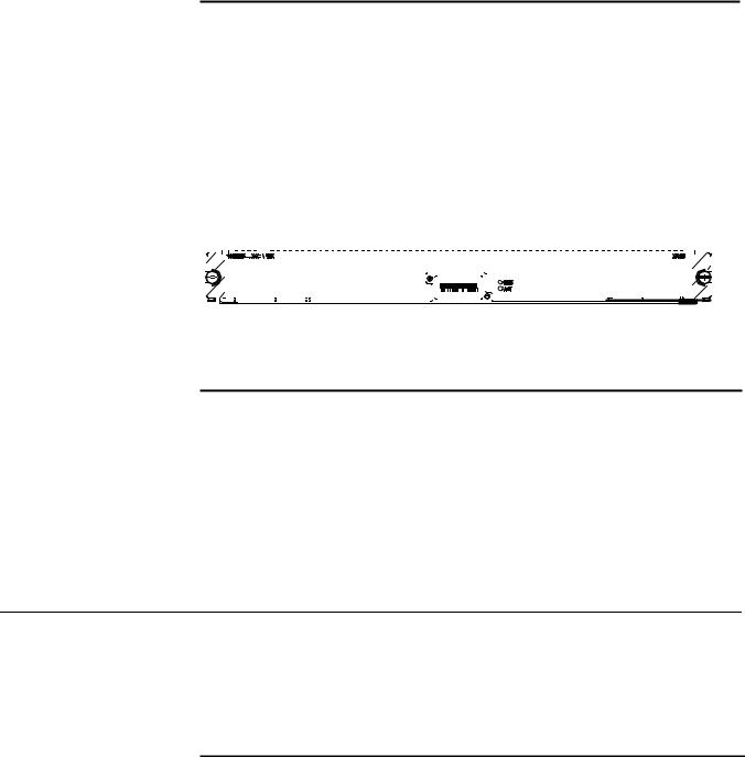
On its panel, the 360 Gbps Switch Fabric provides a CF port, CF LED (CFS), 10Base-T/100Base-TX port, RS232/485 port, Console port, AUX port, RESET button, I/O module status LEDs, and 360 Gbps Switch Fabric status LEDs (SFS, ACT, ALM, RUN) in turn, as shown in Figure 10.

18 CHAPTER 1: PRODUCT OVERVIEW
Figure 10 360 Gbps Switch Fabric panel
Compact Flash (CF slot)
The 360 Gbps Switch Fabric module provides a CF slot to accommodate a standard CF card, where you can save logging information, host version information, alarming and other diagnostic information and conveniently upgrade software online. The fabric ships with a CF memory card.
Management Ports
The Management 10Base-T/100Base-TX port uses an RJ-45 connector. It can connect a background terminal for system program loading and debugging, or connect a network management station for remote system management.
Table 6 Management 10Base-T/100Base-TX port specifications
Item |
Description |
|
|
Connector |
RJ-45 |
Number of ports |
One |
Rate |
10 Mbps, half duplex/full duplex |
|
100 Mbps, half duplex/full duplex |
Max. transmission segment over the selected medium
Service
100 m (328 ft.) over the category-5 twisted pair cable (crossover cable is required).
System program upgrade and network management
The following table describes the status LEDs for the management 10Base-T/100Base-TX port.
Table 7 Status LEDs for the management 10Base-T/100Base-TX port
LED |
Status |
|
|
|
|
LINK |
OFF |
No link is present. |
|
ON |
A link is present. |
ACT |
OFF |
No packets are transmitted/received on the port. |
|
Blinking |
Packets are being transmitted/received on the port. |
|
|
|
■ RS232/485 port
The RS232/485 port uses RJ-45 connector, for connecting external PoE power frame when supported and monitoring its status.
Table 8 RS232/485 port specifications
Item |
Description |
|
|
Connector |
RJ-45 |
Number of ports |
One RS 232 port and one RS485 port |

Fabric Modules 19
Table 8 RS232/485 port specifications
Item |
Description |
|
|
Service |
The port for monitoring and communication with the external subsystem, |
|
such as external PoE power supply module |
|
|
■ Console port
The Console port uses an RJ-45 connector. It can be connected to a background terminal for system debugging, maintenance, management, and host software loading.
Table 9 Console port specifications
Item |
Description |
|
|
Connector |
RJ-45 |
Standard |
Asynchronous EIA/TIA-232 |
Baud rate |
9600 bps (default) |
Transmission |
15 m (49 ft.) |
segment |
|
Service |
Connects a serial port of a local PC and runs terminal emulation on the |
|
PC. |
|
|
n You can choose your own baud rate for the Console port.
■ AUX port
The AUX port uses an RJ-45 connector. The port can serve as a backup port for the Console port to connect a background terminal, or directly connect a modem device, for remote system debugging, configuration, maintenance and management.
Table 10 AUX port specifications
Item |
Description |
|
|
Connector |
RJ-45 |
Standard |
Asynchronous EIA/TIA-232 |
Service |
Connects a serial port of a PC (through a Modem pair for a remote PC) and runs |
|
terminal emulation on the PC. |
|
|
RESET button
You can press the RESET button on the panel to reset the 360 Gbps Switch Fabric module.
Status LEDs
■ CF status LED
You can learn the operating status of the CF card by reading the CF status LED on the panel.

20 CHAPTER 1: PRODUCT OVERVIEW
Table 11 CF status LED
LED |
Status |
|
|
|
|
CFS |
ON |
The CF card is in position and is idle. You cannot remove the card. |
|
Blinking |
The CF card is in position and reading/writing data. You cannot remove |
|
|
the card. |
|
OFF |
The CF card is out of position or offline (you can force the in-position CF |
|
|
card to go offline using the appropriate background command). You can |
|
|
remove/insert the card. |
|
|
|
■ Status LEDs for I/O module
The 360 Gbps Switch Fabric module has 12 pairs of LEDs to indicate the operating status of 12 I/O module.
Table 12 Status LEDs for I/O module
LED |
Status |
|
|
|
|
RUN |
ON |
The module is faulty. |
|
OFF |
The module is faulty or out of position. |
|
Blinking (1s) |
The module is running normally. |
|
Fast blinking (125 ms) |
The module is booting or not registered successfully. |
ALM |
ON |
The module has alarms. |
|
OFF |
The module has no alarms or is out of position. |
0~5, |
Indicate slots 0 through 5 and slots 8 through 13 |
|
8~13 |
|
|
|
|
|
■ Status LEDs for the 360 Gbps Switch Fabric module
You can learn the operating status of 360 Gbps Switch Fabric module by reading the SFS, ACT, ALM and RUN LEDs on it. The following table gives a summary of the four LEDs.
Table 13 Status LEDs for the 360 Gbps Switch Fabric module
360 Gbps Switch |
|
|
|
Fabric LED |
Status |
|
|
|
|
|
|
SFS |
ON |
The switching fabric unit is active. |
|
|
OFF |
The switching fabric unit is standby. |
|
RUN |
Green |
The 360 Gbps Switch Fabric module is faulty. |
|
|
OFF |
The 360 Gbps Switch Fabric module is faulty. |
|
|
Green blinking |
The 360 Gbps Switch Fabric module runs normally. |
|
ALM |
Red |
The 360 |
Gbps Switch Fabric module has alarms. |
|
OFF |
The 360 |
Gbps Switch Fabric module has no alarms. |
ACT |
Green |
The 360 |
Gbps Switch Fabric module is active. |
|
OFF |
The 360 |
Gbps Switch Fabric module is standby. |
|
|
|
|
Fabric Modules 21
720 Gbps Switch Fabric Technical specifications
This model applies to the 3C17539. See Table 5 for its specifications.
Table 14 720 Gbps Switch Fabric specifications
Item |
Specifications |
|
|
CPU |
MPC755 |
Boot ROM |
512 KB |
SDRAM |
512 MB (expandable to 1 GB) |
Physical dimensions (W x D) 366.7 x 340 mm (14.4 x 13.4 in.) |
|
Port |
One Console port, for local configuration management |
|
One AUX port, for remote dialup configuration management |
|
One 10Base-T/100Base-TX port, for software upgrade and |
|
network management |
|
One RS232/485 port, for connecting external PoE power frame |
|
to provide the PoE function |
|
One hot-swap-supported CF port |
Max power consumption |
110 W |
|
|
Panel
On its panel, the 720 Gbps Switch Fabric provides a CF slot, CF LED (CFS), 10Base-T/100Base-TX port, RS232/485 port, Console port, AUX port, RESET button, I/O module status LEDs, and 360 Gbps Switch Fabric status LEDs (SFS, ACT, ALM, RUN) in turn, as shown in Figure 10. The fabric ships with a CF memory card.
Figure 11 720 Gbps Switch Fabric panel
Compact Flash (CF slot)
The 720 Gbps Switch Fabric module provides a CF port to accommodate a standard CF card, where you can save logging information, host version information, alarming and other diagnostic information and conveniently upgrade software online.
Management Ports
The Management 10Base-T/100Base-TX port uses an RJ-45 connector. It can connect a background terminal for system program loading and debugging, or connect a network management station for remote system management.
Table 15 Management 10Base-T/100Base-TX port specifications
Item |
Description |
|
|
Connector |
RJ-45 |
Number of ports |
One |
Rate |
10 Mbps, half duplex/full duplex |
|
100 Mbps, half duplex/full duplex |

22 CHAPTER 1: PRODUCT OVERVIEW
Table 15 Management 10Base-T/100Base-TX port specifications
Item |
Description |
Max. transmission segment over the selected medium
Service
100 m (328 ft.) over the category-5 twisted pair cable (crossover cable is required).
System program upgrade and network management
The following table describes the status LEDs for the management 10Base-T/100Base-TX port.
Table 16 Status LEDs for the management 10Base-T/100Base-TX port
LED |
Status |
|
|
|
|
LINK |
OFF |
No link is present. |
|
ON |
A link is present. |
ACT |
OFF |
No packets are transmitted/received on the port. |
|
Blinking |
Packets are being transmitted/received on the port. |
|
|
|
■ RS232/485 port
The RS232/485 port uses RJ-45 connector, for connecting external PoE power frame when supported and monitoring its status.
Table 17 RS232/485 port specifications
Item |
Description |
|
|
Connector |
RJ-45 |
Number of ports |
One RS 232 port and one RS485 port |
Service |
The port for monitoring and communication with the external subsystem, |
|
such as external PoE power supply module |
|
|
■ Console port
The Console port uses an RJ-45 connector. It can be connected to a background terminal for system debugging, maintenance, management, and host software loading.
Table 18 Console port specifications
Item |
Description |
|
|
Connector |
RJ-45 |
Standard |
Asynchronous EIA/TIA-232 |
Baud rate |
9600 bps (default) |
Transmission |
15 m (49 ft.) |
segment |
|
Service |
Connects a serial port of a local PC and runs terminal emulation on the |
|
PC. |
|
|
n You can choose your own baud rate for the Console port.
■ AUX port

Fabric Modules 23
The AUX port uses an RJ-45 connector. The port can serve as a backup port for the Console port to connect a background terminal, or directly connect a modem device, for remote system debugging, configuration, maintenance and management.
Table 19 AUX port specifications
Item |
Description |
|
|
Connector |
RJ-45 |
Standard |
Asynchronous EIA/TIA-232 |
Service |
Connects a serial port of a PC (through a Modem pair for a remote PC) and runs |
|
terminal emulation on the PC. |
|
|
RESET button
You can press the RESET button on the panel to reset the 720 Gbps Switch Fabric module.
Status LEDs
■ CF status LED
You can learn the operating status of the CF card by reading the CF status LED on the panel.
Table 20 CF status LED
LED |
Status |
|
|
|
|
CFS |
ON |
The CF card is in position and is idle. You cannot remove the card. |
|
Blinking |
The CF card is in position and reading/writing data. You cannot remove |
|
|
the card. |
|
OFF |
The CF card is out of position or offline (you can force the in-position CF |
|
|
card to go offline using the appropriate background command). You can |
|
|
remove/insert the card. |
|
|
|
■ Status LEDs for I/O module
The 720 Gbps Switch Fabric module has 12 pairs of LEDs to indicate the operating status of 12 I/O module.
Table 21 Status LEDs for I/O module
LED |
Status |
|
|
|
|
RUN |
ON |
The module is faulty. |
|
OFF |
The module is faulty or out of position. |
|
Blinking (1s) |
The module is running normally. |
|
Fast blinking (125 ms) |
The module is booting or not registered successfully. |
ALM |
ON |
The module has alarms. |
|
OFF |
The module has no alarms or is out of position. |
0~5, |
Indicate slots 0 through 5 and slots 8 through 13 |
|
8~13 |
|
|
|
|
|
■ Status LEDs for the 720 Gbps Switch Fabric module

24 CHAPTER 1: PRODUCT OVERVIEW
You can learn the operating status of 720 Gbps Switch Fabric module by reading the SFS, ACT, ALM and RUN LEDs on it. The following table gives a summary of the four LEDs.
Table 22 Status LEDs for the 720 Gbps Switch Fabric module
360 Gbps Switch |
|
|
|
Fabric LED |
Status |
|
|
|
|
|
|
SFS |
ON |
The switching fabric unit is active. |
|
|
OFF |
The switching fabric unit is standby. |
|
RUN |
Green |
The 720 Gbps Switch Fabric module is faulty. |
|
|
OFF |
The 720 Gbps Switch Fabric module is faulty. |
|
|
Green blinking |
The 720 Gbps Switch Fabric module runs normally. |
|
ALM |
Red |
The 720 |
Gbps Switch Fabric module has alarms. |
|
OFF |
The 720 |
Gbps Switch Fabric module has no alarms. |
ACT |
Green |
The 720 |
Gbps Switch Fabric module is active. |
|
OFF |
The 720 |
Gbps Switch Fabric module is standby. |
|
|
|
|
RESET button
You can press the RESET button on the panel to reset the 720 Gbps Switch Fabric.
Status LEDs
See the section “Status LEDs” on page 19.
System Specifications The following table summarizes the physical specifications of the Switch 8800 Family.
Table 23 Technical specifications of the Switch 8800 Family
Item |
Switch 8807 |
Switch 8810 |
Switch 8814 |
|
|
|
|
Dimensions |
486 x 436 x 450 mm |
619 x 436 x 450 mm |
753 x 436 x 450 mm |
(H x W x D) |
(19.1 x 17.2 x 17.7 |
(24.4 x 17.2 x 17.7 |
(29.6 x 17.2 x 17.7 in.) |
|
in.) |
in.) |
|
|
|
|
|
Weight (full load) |
600 kg (143 lb) |
80 kg (176 lb) |
100 kg (220 lb) |
|
|
|
|
Max power |
1200 W |
2000 W |
2000 W |
consumption |
|
|
|
|
|
|
|
Switching |
Fab360: 600 Gbps |
Fab360: 480Gbps |
Fab360: 720Gbps |
capacity (see |
(see Note 2) |
Fab720: 960Gbps |
Fab720: 1440Gbps |
Note 1) |
|
||
|
|
|
|
|
|
|
|
Number of |
4 K |
|
|
VLANs |
|
|
|
|
|
||
Maximum MAC |
14 K/per module, total 14 K x number of modules |
||
address table size |
See Note 3 |
|
|
|
|
|
|
Forwarding table |
128 K/256 K |
|
|
entries |
|
|
|
|
|
|
|
Number of fabric |
2 |
2 |
2 |
slots |
|
|
|

|
|
|
|
Software Features 25 |
|
|
Table 23 Technical specifications of the Switch 8800 Family |
|
|
||
|
|
|
|
|
|
|
Item |
Switch 8807 |
Switch 8810 |
Switch 8814 |
|
|
|
|
|
|
|
|
fabric module |
360 Gbps Fabric |
360 Gbps Switch |
360 Gbps Switch Fabric |
|
|
type |
|
Fabric |
720 Gbps Switch Fabric |
|
|
|
|
720 Gbps Switch |
||
|
|
|
|
|
|
|
|
|
Fabric |
|
|
|
|
|
|
|
|
|
Number of I/O |
5 |
8 |
12 |
|
|
module slots |
|
|
|
|
|
|
|
|
|
|
|
User interface |
10/100/1000BASE-TX RJ45 |
|
|
|
|
|
1000BASE-X (SFP) |
|
|
|
|
|
10BASE-X (XENPAK) |
|
|
|
|
|
10BASE-X (XFP) |
|
|
|
|
|
|
|
|
|
|
Operating |
0 to 40C (32 to 104F) |
|
|
|
|
temperature |
|
|
|
|
|
|
|
|
|
|
|
Operating |
10% to 90% |
|
|
|
|
humidity |
|
|
|
|
|
(noncondensing) |
|
|
|
|
|
|
|
|
|
|
|
Storage |
-10 to 70C (14 to 158F) |
|
|
|
|
temperature |
|
|
|
|
|
|
|
|
|
|
|
Storage humidity |
10% to 90% |
|
|
|
|
|
|
|||
n |
Note 1: The switching capacity in the above table is calculated based on two |
||||
|
load-sharing fabrics. |
|
|
|
|
Note 2: The 7-slot has additional backplane traces per slot compared to the 14-slot and the 10slot chassis. The additional traces enable higher capacity per slot using the 360G Fabric compared to the 10-slot and 14-slot chassis.
Note 3: See the Switch 8800 Configuration Guide for rules and limitations.
Software Features |
The software of the Switch 8800 Family uses fully distributed processing and runs |
|
|
on 3Com network operating system Comware. The following table summaries the |
|
|
supported software features. |
|
|
Table 24 Software features of the Switch 8800 Family |
|
|
|
|
|
Item |
Description |
|
|
|
|
VLAN |
IEEE 802.1Q-compliant VLAN |
|
|
Port-based, protocol-based (8 groups), IP subnet-based |
|
|
VLAN division |
|
|
GARP VLAN registration protocol (GVRP) |
|
|
Super VLAN |
|
|
Isolate user VLAN |
|
|
Guest VLAN |
|
|
Dynamic VLAN |
|
STP |
IEEE 802.1d/IEEE 802.1w/IEEE 802.1s-compliant |
|
|
spanning tree protocol (STP)/rapid STP (RSTP)/multiple |
|
|
STP (MSTP) |

26 CHAPTER 1: PRODUCT OVERVIEW
Table 24 Software features of the Switch 8800 Family
Item |
Description |
|
|
Flow control |
IEEE 802.3x flow control (full duplex) |
|
Back pressure flow control (half duplex) |
Broadcast/multicast suppression |
Supported |
Multicast |
Internet group management protocol (IGMP) snooping |
|
IGMP |
|
Internet group management protocol (IGMP) v2 |
|
Protocol-independent multicast-dense mode (PIM-DM) |
|
Protocol-independent multicast-sparse mode (PIM-SM) |
|
Multicast source discovery protocol (MSDP) |
|
Multiprotocol border gateway protocol (MBGP) |
|
Any-RP |
IP routing |
Static routing |
|
Routing information protocol (RIP) v1/v2 |
|
Open shortest path first (OSPF) v2 |
|
Border gateway protocol (BGP) |
|
Intermediate system-to-intermediate system (IS-IS) |
|
Equal cost route forwarding |
|
Routing policy |
|
Policy routing |
|
OSPF/IS-IS/BGP graceful restart (GR) |
Link aggregation |
Aggregation across cards |
|
LACP |
DHCP |
DHCP server |
|
DHCP relay |
|
DHCP Option 82 |
Mirroring |
Port-based mirroring |
Multiprotocol Label Switching (MPLS) |
L3 MPLS VPN, inter-domain MPLS VPN, hierarchy of PE |
|
(HoPE), CE dual homing, MCE, multi-role host |
|
VLL: Martini, Kompella, and CCC mode |
|
VPLS |
QoS |
Traffic classification based on port, MAC address, |
|
VLAN, IP address, IP priority, TCP/UDP port number, |
|
DSCP priority, Type of service (ToS) priority, class of |
|
service (CoS) priority, etc. |
|
Traffic monitoring, with granularity of 8 Kbps |
|
Traffic shaping |
|
Priority mark/remark |
|
Queue scheduling: strict priority (SP), weighted round |
|
Robin (WRR) and SP + WRR <par |
|
8 priority queues for each port |
|
Congestion avoidance algorithms: tail drop (TD) and |
|
weighted random early detection (WRED) |
|
|
Software Features 27 |
|
Table 24 Software features of the Switch 8800 Family |
|
|
|
|
|
Item |
Description |
|
|
|
|
Security |
Hierarchical user management and password |
|
|
protection |
|
|
Password control |
|
|
802.1x authentication |
|
|
Packet filtering |
|
|
Port-based broadcast frame suppression, speed |
|
|
calculation in bytes or packets |
|
|
Protection from attacks by virus packets, such as DOS |
|
|
attacks |
|
|
AAA/RADIUS/HWTACACS |
|
|
SSH 2.0 (security shell) |
|
|
Firewall |
|
|
IPsec |
|
|
Education network accounting |
|
QinQ |
Port VLAN VPN |
|
|
Flexible QinQ |
|
Network Monitoring feature |
NetFlow v5/v8/v9 |
|
Management and maintenance |
Configuration through the command line interface |
|
|
(CLI) |
|
|
Configuration through the Console/AUX port |
|
|
Telnet configuration/maintenance through Ethernet |
|
|
ports |
|
|
Modem dialup configuration/maintenance through |
|
|
AUX port |
|
|
SNMP management, with the 3Com network |
|
|
management application, RMON (remote monitoring), |
|
|
and 1/2/3/9 groups of MIBs. |
|
|
System logging |
|
|
Hierarchical alarming |
|
|
Debugging information output |
|
|
ping and tracert commands |
|
|
NQA |
|
Loading and upgrade |
Loading and upgrade using the XModem protocol |
|
|
Loading and upgrade using FTP/TFTP |
|
|
Loading of BootROM and host software |
|
|
|
n |
All specifications are subject to changes without notice. For up-to-date |
|
|
information, please contact 3Com marketing or technical support personnel. |
|
28 CHAPTER 1: PRODUCT OVERVIEW

I/O AND APPLICATION MODULES
2
Overview |
The Switch 8800 Family are modular switches that are designed following industry |
|
standards. The following I/O modules are available to the Switch 8800 Family: |
|
Table 25 I/O modules available to the Switch 8800 Family |
I/O module |
User interface |
|
|
3C17511 |
1-port 10GBASE-X (XENPAK) |
3C17512 |
2-port 10GBASE-X (XFP) |
3C17513 |
12-port 1000BASE-X (SFP) |
3C17514 |
24-port 1000BASE-X (SFP) |
3C17516 |
24-port 10/100/1000BASE-T (RJ-45) |
3C17525 |
1-port 10GBASE-X (XENPAK) Advanced |
3C17526 |
4-port 10GBASE-X (XFP) |
3C17527 |
2-port 10GBASE-X (XFP) Advanced |
3C17528 |
48-port 10/100/1000 BASE-T (RJ-45) |
3C17530 |
24-port 1000BASE-X (SFP) Advanced |
3C17531 |
24-port 10/100/1000BASE-T (RJ-45) Advanced |
3C17532 |
48-port 10/100/1000BASE-T (RJ-45) Access |
3C17533 |
24-port 1000BASE-X (SFP) IPv6 Module |
3C17534 |
24-port 10/100/1000BASE-T (RJ-45) IPv6 Module |
3C17536 |
4-port 10GBASE-X (XFP) QUAD IPv6 |
3C17537 |
2-port 10GBASE-X (XFP) |
3C17538 |
48-port 1000BASE-X (SFP) IPv6 |
3C17542 |
Network Monitoring Module |
3C17546 |
Firewall Module |
3CR1754766 |
IPsec Module |
3C17548 |
Virtual Private LAN Service (VPLS) |
|
|
3C17511 1-port 10GBASE-X (XENPAK)
Specifications This section provides specifications for the 1-port 10GBASE-X (XENPAK) 3C17511 module.
Table 26 3C17511 module specifications
Item |
Specification |
|
|
CPU |
MPC8245 |
30 CHAPTER 2: I/O AND APPLICATION MODULES
Table 26 3C17511 module specifications
|
|
Item |
|
|
|
|
|
|
Specification |
|||||||||||||||||||||||||||||||||||||||||||||||||
|
|
|
|
|
|
|
|
|
|
|
|
|
|
|
|
|
|
|
|
|
|
|
|
|
|
|
|
|
|
|
|
|
|
|
|
|
|
|
|
|
|
|
|
|
|
|
|
|
|
|
|
|
|
|
|
|
|
|
|
|
Boot ROM |
|
|
|
|
|
|
512 KB |
|||||||||||||||||||||||||||||||||||||||||||||||||
|
|
SDRAM |
|
|
|
|
|
|
128 MB/256 MB |
|||||||||||||||||||||||||||||||||||||||||||||||||
|
|
Physical dimensions (W x D) |
|
|
|
|
|
|
366.7 x 340 mm(14.4 x 13.4 in.) |
|||||||||||||||||||||||||||||||||||||||||||||||||
|
|
Max power consumption |
|
|
|
|
|
|
45 W |
|||||||||||||||||||||||||||||||||||||||||||||||||
|
|
Number of ports |
|
|
|
|
|
|
One |
|||||||||||||||||||||||||||||||||||||||||||||||||
|
|
Connector |
|
|
|
|
|
|
XENPAK/SC |
|||||||||||||||||||||||||||||||||||||||||||||||||
|
|
Rate |
|
|
|
|
|
|
10 Gbps |
|||||||||||||||||||||||||||||||||||||||||||||||||
|
|
|
|
|
|
|
|
|
|
|
|
|
|
|
|
|
|
|
|
|
|
|
|
|
|
|
|
|
|
|
|
|
|
|
|
|
|
|
|
|
|
|
|
|
|
|
|
|
|
|
|
|
|
|
|
|
|
|
Panel and LEDs Figure 12 3C17511 module panel |
|
|
|
|
|
|
|
|
|
|
|
|
|
|
|
|
|
|
|
|
|
|
|
|
|
|
|
|
|
|
|
|
|
|
||||||||||||||||||||||||
|
|
|
|
|
|
|
|
|
|
|
|
|
|
|
|
|
|
|
|
|
|
|
|
|
|
|
|
|
|
|
|
|
|
|
|
|
|
|
|
|
|
|
|
|
|
|
|
|
|
|
|
|
|
|
|
|
|
|
|
|
|
|
|
|
|
|
|
|
|
|
|
|
|
|
|
|
|
|
|
|
|
|
|
|
|
|
|
|
|
|
|
|
|
|
|
|
|
|
|
|
|
|
|
|
|
|
|
|
|
|
|
|
|
|
|
|
|
The 3C17511 module has two port LEDs for the 10GE port on its panel.
Table 27 Port LEDs on the 3C17511 module
LED |
Status |
Meaning |
|
|
|
LINK |
OFF |
No link is present. |
|
Green ON |
A link is present. |
ACT |
OFF |
No packets are transmitted/received on the port. |
|
Orange blinking |
Packets are being transmitted/received on the port. |
|
|
|
Matching Cable See Table 66 on page 46 for the XENPAK optical modules available to the 10GE XENPAK/SC optical/electrical port on the 3C17511 module and their matching cable types, which you can select as required.
3C17512 2-port 10GBASE-X (XFP) Module
This section provides specifications for the 2-port 10GBASE-X (XFP) module (3C17512).
Specifications The 3C17512 modules provide two 10GBASE-X XFP/LC ports.
Table 28 3C17512 module specifications
Item |
Specification |
|
|
CPU |
MPC8245 |
Boot ROM |
512 KB |
SDRAM |
128 MB/256MB |
Physical dimensions (W x D) |
366.7 x 340 mm (14.4 x 13.4 in.) |
Max power consumption |
87 W |
Number of ports |
Two |
Connector |
XFP |
Loading...