

Page 1

3Com® Switch 8800 Family
Installation Guide
Switch 8807
Switch 8810
Switch 8814
www.3Com.com
Part No. 10015593, Rev. AA
Published: January 2007
Page 2

3Com Corporation
350 Campus Drive
Marlborough, MA
USA 01752-3064
Copyright © 2006-2007, 3Com Corporation. All rights reserved. No part of this documentation may be reproduced in any
form or by any means or used to make any derivative work (such as translation, transformation, or adaptation) without
written permission from 3Com Corporation.
3Com Corporation reserves the right to revise this documentation and to make changes in content from time to time
without obligation on the part of 3Com Corporation to provide notification of such revision or change.
3Com Corporation provides this documentation without warranty, term, or condition of any kind, either implied or
expressed, including, but not limited to, the implied warranties, terms or conditions of merchantability, satisfactory quality,
and fitness for a particular purpose. 3Com may make improvements or changes in the product(s) and/or the program(s)
described in this documentation at any time.
If there is any software on removable media described in this documentation, it is furnished under a license agreement
included with the product as a separate document, in the hard copy documentation, or on the removable media in a
directory file named LICENSE.TXT or !LICENSE.TXT. If you are unable to locate a copy, please contact 3Com and a copy will
be provided to you.
UNITED STATES GOVERNMENT LEGEND
If you are a United States government agency, then this documentation and the software described herein are provided to
you subject to the following:
All technical data and computer software are commercial in nature and developed solely at private expense. Software is
delivered as “Commercial Computer Software” as defined in DFARS 252.227-7014 (June 1995) or as a “commercial item”
as defined in FAR
license for the Software. Technical data is provided with limited rights only as provided in DFAR 252.227-7015 (Nov
FAR 52.227-14 (June 1987), whichever is applicable. You agree not to remove or deface any portion of any legend provided
on any licensed program or documentation contained in, or delivered to you in conjunction with, this User Guide.
Unless otherwise indicated, 3Com registered trademarks are registered in the United States and may or may not be registered
in other countries.
3Com and the 3Com logo are registered trademarks of 3Com Corporation.
Cisco is a registered trademark of Cisco Systems, Inc.
Funk RADIUS is a registered trademark of Funk Software, Inc.
Aegis is a registered trademark of Aegis Group PLC.
Intel and Pentium are registered trademarks of Intel Corporation. Microsoft, MS-DOS, Windows, and Windows NT are
registered trademarks of Microsoft
registered trademark in the United States and other countries, licensed exclusively through X/Open Company, Ltd.
IEEE and 802 are registered trademarks of the Institute of Electrical and Electronics Engineers, Inc.
All other company and product names may be trademarks of the respective companies with which they are associated.
2.101(a) and as such is provided with only such rights as are provided in 3Com’s standard commercial
Corporation. Novell and NetWare are registered trademarks of Novell, Inc. UNIX is a
1995) or
ENVIRONMENTAL STATEMENT
It is the policy of 3Com Corporation to be environmentally-friendly in all operations. To uphold our policy, we are committed
to:
Establishing environmental performance standards that comply with national legislation and regulations.
Conserving energy, materials and natural resources in all operations.
Reducing the waste generated by all operations. Ensuring that all waste conforms to recognized environmental standards.
Maximizing the recyclable and reusable content of all products.
Ensuring that all products can be recycled, reused and disposed of safely.
Ensuring that all products are labelled according to recognized environmental standards.
Improving our environmental record on a continual basis.
End of Life Statement
3Com processes allow for the recovery, reclamation and safe disposal of all end-of-life electronic components.
Regulated Materials Statement
3Com products do not contain any hazardous or ozone-depleting material.
Page 3

CONTENTS
ABOUT THIS GUIDE
Conventions 5
Related Documentation 6
1 PRODUCT OVERVIEW
Preface 7
General Architecture 10
Fabric Modules 17
System Specifications 24
Software Features 25
2 I/O AND APPLICATION MODULES
Overview 29
3C17511 1-port 10GBASE-X (XENPAK) 29
3C17512 2-port 10GBASE-X (XFP) Module 30
3C17513 12-port 1000BASE-X (SFP) Module 31
3C17514 24-port 1000BASE-X (SFP) Module 32
3C17516 24-port 10/100/1000BASE-T Module 33
3C17525 1-port 10GBASE-X Advanced (XENPAK) Module 33
3C17526 4-port 10GBASE-X (XFP) Module 34
3C17527 2-port 10GBASE-X (XFP) Advanced Module 35
3C17528 48port 10/100/1000 BASE-T (RJ-45) Module 36
3C17530 24-port 1000BASE-X (SFP) Advanced Module 37
3C17531 24-port 10/100/1000BASE-T Advanced Module 37
3C17532 48-port 10/100/1000 BASE-T (RJ-45) Access Module 38
3C17533 24-port 1000BASE-X (SFP) IPv6 Module 39
3C17534 24-port 10/100/1000BASE-T IPv6 Module 40
3C17536 4-port 10GBASE-X (XFP) QUAD IPv6 Module 40
3C17538 48-port 1000BASE-X (SFP) IPv6 Module 41
Application Modules 42
Transceivers 45
Switch 8800 Port Densities 46
3 INSTALLATION PREPARATION
Safety Recommendations 47
Examining Installation Site 48
Installation Tools 50
Page 4

4 SWITCH INSTALLATION
Confirming Installation Preparation 51
Installation Flow 51
Mounting the Switch in User-Supplied Cabinet 52
Connecting PGND Wire and Power Cord 57
Installing Cabling Rack 62
Installing Fan Tray 62
Installing PoE Lightning Protection Box 63
Installing I/O modules 64
Connecting Interface Cables 65
Cable Routing Recommendations 68
Cable Management 68
Verifying the Installation 71
5 SYSTEM DEBUGGING
Setting up Configuration Environment 73
Powering and Booting the Switch 74
6 SWITCH MONITORING AND MAINTENANCE
Monitoring the Switch 77
Hardware Maintenance 79
Software Upgrade 84
Password Loss 93
A LIGHTNING PROTECTION OF THE SWITCH
Installation of Lightning Arrester for AC Power (Socket Strip with Lightning
Protection) 95
Installation of Lightning Arrester for Network Port 96
Page 5

ABOUT THIS GUIDE
This guide describes the 3Com® Switch 8800 and how to install hardware,
configure and boot software, and maintain software and hardware. This guide
also provides troubleshooting and support information for your switch.
This guide is intended for Qualified Service personnel who are responsible for
configuring, using, and managing the switches. It assumes a working knowledge
of local area network (LAN) operations and familiarity with communication
protocols that are used to interconnect LANs.
n
Conventions Ta bl e 1 lists icon conventions that are used throughout this guide.
Always download the Release Notes for your product from the 3Com World Wide
Web site and check for the latest updates to software and product
documentation:
http://www.3com.com
Ta bl e 1 Notice Icons
Icon Notice Type Description
Information note Information that describes important features or
n
Caution Information that alerts you to potential loss of data
c
Warning Information that alerts you to potential personal
w
Ta bl e 2 lists text conventions that are used throughout this guide.
Ta bl e 2 Text Conventions
instructions.
or potential damage to an application, system, or
device.
injury.
Convention Description
Screen displays This typeface represents information as it appears on the
screen.
Keyboard key names If you must press two or more keys simultaneously, the key
names are linked with a plus sign (+), for example:
Press Ctrl+Alt+Del
The words “enter” and “type” When you see the word “enter” in this guide, you must type
something, and then press Return or Enter. Do not press
Return or Enter when an instruction simply says “type.”
Page 6

6 ABOUT THIS GUIDE
Table 2 Text Conventions
Convention Description
Words in italics Italics are used to:
Emphasize a point.
Denote a new term at the place where it is defined in the
text.
Identify menu names, menu commands, and software
button names.
Examples:
From the Help menu, select Contents.
Click OK.
Words in bold Boldface type is used to highlight command names. For
example, “Use the display user-interface command
to...”
Related Documentation
The following manuals offer additional information necessary for managing your
Switch 8800:
■ Switch 8800 Command Reference Guide — Provides detailed descriptions of
command line interface (CLI) commands, that you require to manage your
Switch 8800.
■ Switch 8800 Configuration Guide— Describes how to configure your Switch
8800 using the supported protocols and CLI commands.
■ Switch 8800 Release Notes — Contains the latest information about your
product. If information in this guide differs from information in the release
notes, use the information in the Release Notes.
These documents are available in Adobe Acrobat Reader Portable Document
Format (PDF) on the 3Com World Wide Web site:
http://www.3com.com/
Page 7

PRODUCT OVERVIEW
1
Preface 3Com Switch 8800 Family of Routing Switches (hereinafter referred to as Switch
8800 Family) are intelligent, multi-layer modular LAN switches is ideal for
enterprise environments where non-stop availability of critical applications and the
highest performance, security, and granular control are required. The Switch 8800
Family delivers high density Gigabit and 10 Gigabit switching in an integrated
chassis platform. Built-in support for IPv6, MPLS, Power over Ethernet (PoE), and
1.44 Tbps backplane capacity ensures unprecedented investment protection.
Resilient Layer-3 routing, hot-swap modules, and redundant power, along with
sub one-second fabric fail over on the Switch 8800, ensure (24 x 7) availability to
support the most demanding enterprise core and campus environments.
Advanced Quality of Service features such as bandwidth management and packet
classification optimize quality for real-time voice and video applications. Intrusion
prevention security capabilities such as IEEE 802.1X Network Login and Access
Control Lists ensure that only authorized users can access network resources.
The Switch 8800 is focused on delivering functionality towards the higher end of
the large Enterprise, with a 4-port 10 Gigabit Module, high density 48-port
Gigabit Modules, as well as a group of Advanced Modules with support for larger
routing tables and/or MPLS. Power over Ethernet (PoE) is built into all Switch
8800s.
Application modules for the Switch 8800 provide the flexibility to add a firewall,
IPsec encryption, network monitoring with NetFlow, and Layer 2 VPN networking
using Virtual Private LAN Service (VPLS) by simply adding a module to the chassis.
Page 8
8 CHAPTER 1: PRODUCT OVERVIEW
Currently, the Switch 8800 Family include the following models:
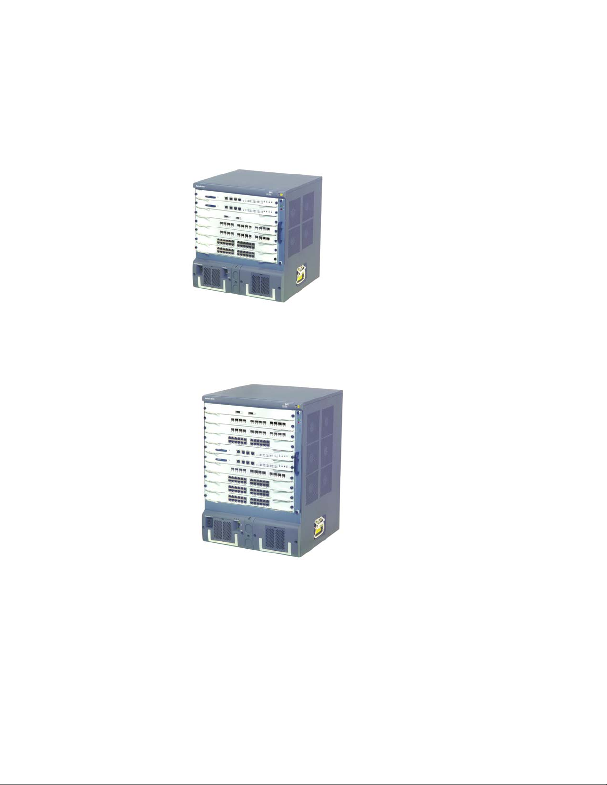
■ Switch 8807: This model provides up to 600 Gbps switching capacity. It
Figure 1 3Com Switch 8807 (7-Slot Chassis)
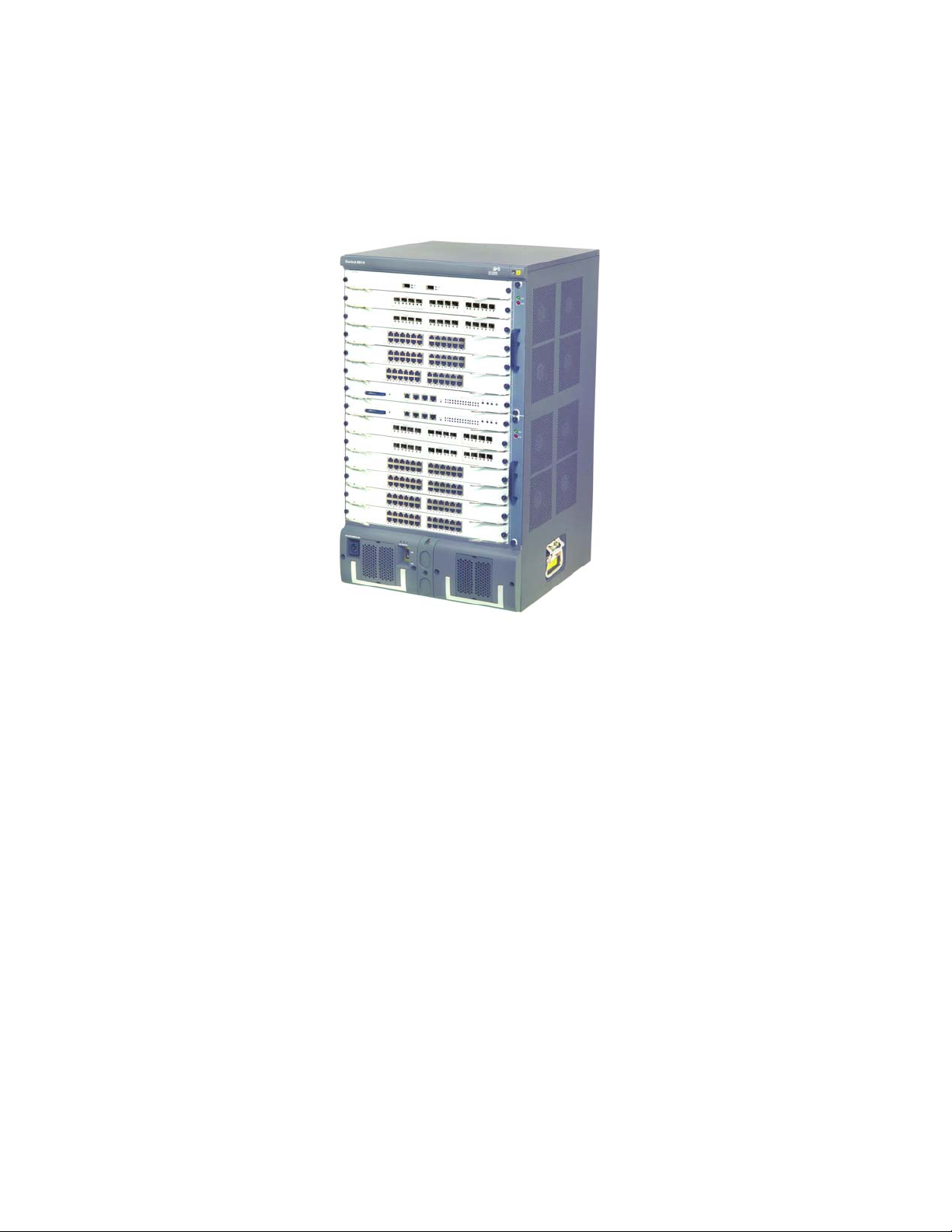
■ Switch 8810: This model provides up to 960 Gbps switching capacity. It
supports (for example) up to 240 GE ports and 20 x 10GE ports.
supports (for example) up to 192 GE ports and 32 x 10GE ports.
Figure 2 3Com Switch 8810 (10-Slot Chassis)
Page 9
Preface 9
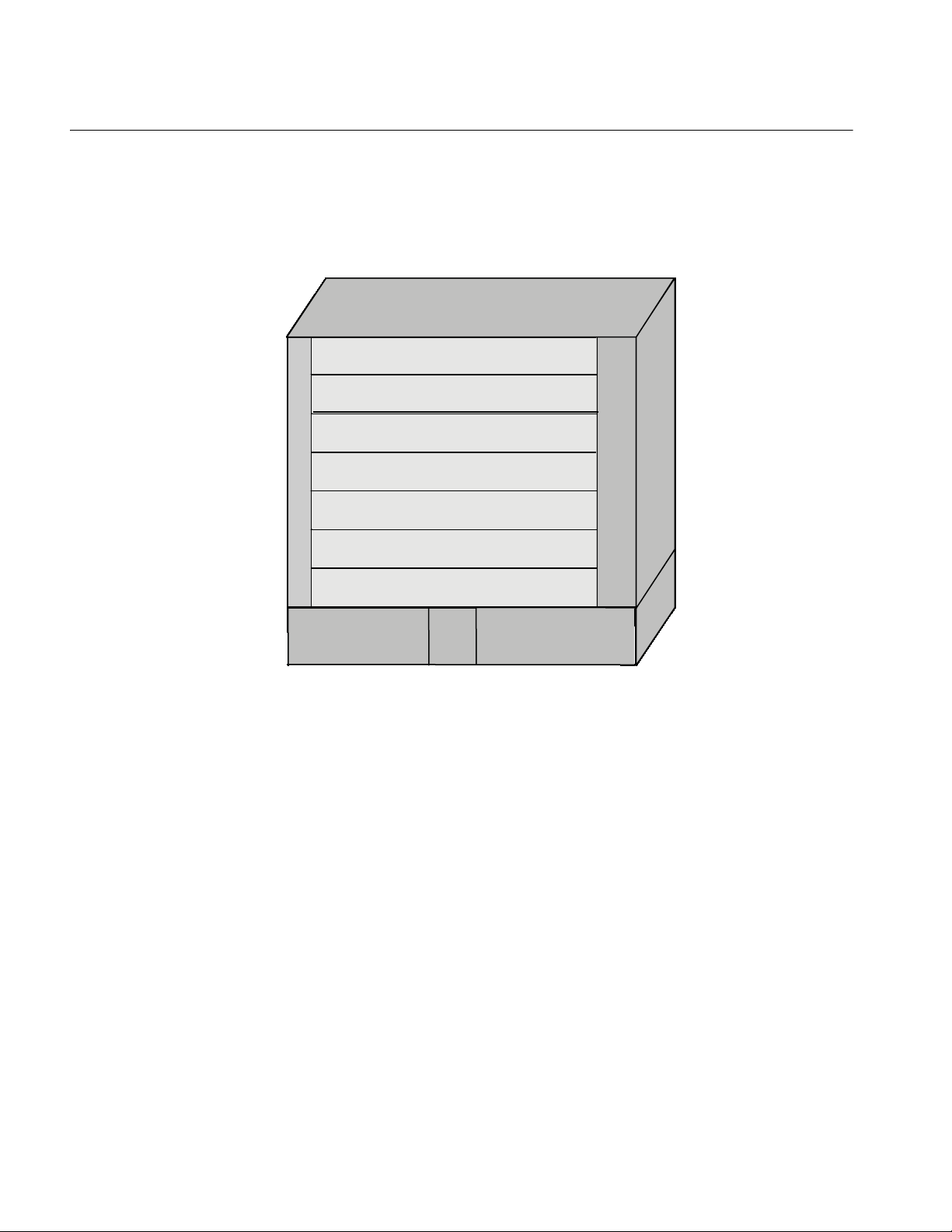
■ Switch 8814: This model provides up to 1.44 Tbps switching capacity. It
supports (for example) up to 576 GE ports and 48 x 10GE ports.
Figure 3 3Com Switch 8814 (14-Slot Chassis)
Page 10
10 CHAPTER 1: PRODUCT OVERVIEW
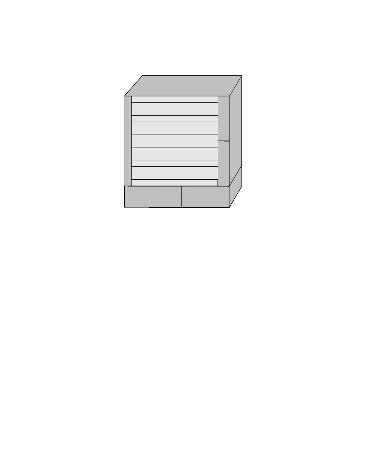
General Architecture The Switch 8800 Family use integrated chassis, which can be subdivided into
power area, board area, backplane and fan area.
Chassis and Slots Switch 8807
Figure 4 Switch 8807 slots
Fabric
Fabric
I/O Module
Fan tray
I/O Module
I/O Module
I/O Module
I/O Module
AC PSU
■ The Switch 8807 chassis provides seven slots in its board area: The top two
PoE
Entry
AC PSU
accommodate fabrics, which can operate in 1+1 redundancy mode; the
remaining five accommodate I/O or application modules, which you can select
from various available models. All modules in this area are hot-swappable.
■ At the bottom of the chassis is the power area that can accommodate one PoE
entry module and two PSUs. The two PSUs are online-swappable; they can
operate in 1+1 redundancy mode. The switch supports AC power inputs.
■ On the right of the chassis is the fan area that contains one vertical
hot-swappable fan tray. The fan tray draws and exhausts air from left to right.
Page 11

Switch 8810
Figure 5 Switch 8810 slots
I/O Module
I/O Module
I/O Module
I/O Module
Fabric
Fabric
I/O Module
I/O Module
I/O Module
I/O Module
General Architecture 11
Fan tray
AC PSU
■ The Switch 8810 chassis provides ten slots in its board area: The middle two
PoE
Entry
AC PSU
accommodate fabric modules, which can operate in 1+1 redundancy mode;
the remaining eight accommodate I/O or application modules, which you can
select from various available models. All modules in this area are
hot-swappable.
■ At the bottom of the chassis is the power area that can accommodate one PoE
entry module and two PSUs. The two PSUs are online-swappable; they can
operate in 1+1 redundancy mode. The switch supports AC power inputs.
■ On the right of the chassis is the fan area that contains one vertical
hot-swappable fan tray. The fan tray draws and exhausts air from left to right.
Page 12
12 CHAPTER 1: PRODUCT OVERVIEW
Switch 8814
Figure 6 Switch 8814 slots
I/O Module
I/O Module
I/O Module
I/O Module
I/O Module
I/O Module
Fabric
Fabric
I/O Module
I/O Module
I/O Module
I/O Module
I/O Module
I/O Module
AC PSU
■ The Switch 8814 chassis provides 14 slots in its board area: The middle two
PoE
entry
AC PSU
Fan tray 1 Fan tray 2
accommodate fabric modules, which can operate in 1+1 redundancy mode;
the remaining 12 accommodate I/O or application modules, which you can
select from various available models. All modules in this area are
hot-swappable.
■ At the bottom of the chassis is the power area that can accommodate one PoE
entry module and two PSUs. The two PSUs are online-swappable. The switch
supports AC power inputs.
■ On the right of the chassis is the fan area that contains two vertical
hot-swappable fan trays. The fan trays draw and exhaust air from left to right.
Backplane The backplane of the Switch 8800 Family allows high-speed data exchange
between fabrics and I/O modules, as well as the exchange of various management
and control signals in the system.
Functions
The following are the main functions of the backplane:
■ Providing communication channels for signal exchange between boards
■ Supporting board hot-swapping
■ Supporting auto-discovering boards in slots
■ Connecting PSUs, distributing power and providing monitor channels to
various components (PSUs, fabrics and I/O modules) in the chassis.
Structure
■ Switch 8807
Page 13

AC Power System
General Architecture 13
The Switch 8807 uses a passive backplane, which provides five I/O module
interfaces, two fabric interfaces, one fan interface, and three -48V power
interfaces (two for PSUs and one for PoE entry module).
■ Switch 8810
The Switch 8810 uses a passive backplane, which provides eight I/O module
interfaces, two fabric interfaces, one fan interface, and three -48V power
interfaces (two for PSUs and one for PoE entry module).
■ Switch 8814
The Switch 8814 uses a passive backplane, which provides 12 I/O module
interfaces, two fabric interfaces, two fan interfaces, and three -48V power
interfaces (two for PSUs and one for PoE entry module).
n
■ The Switch 8800 Family supports AC power inputs.
■ The Switch 8800 Family supports 1+1 power supply redundancy.
■ The PSUs of the Switch 8800 Family are online-swappable.
The Switch 8800 Family supports AC power inputs. The power frame is at the
bottom of the chassis, with a height of 3U. In the same slot, you can insert an AC
PSU. The power frame is in different compartment from the functional board
frame and connected to the latter with cables, which are routed along the back of
the chassis. The power supply is cooled by built-in fans of the PSUs, which draw air
into the chassis from the front and exhaust air out of the chassis from the back.
Ta bl e 1 Specifications for AC PSUs
Specifications
Item
Rated voltage
range
Max voltage range 90 to 264 VAC, 50/60
Max input current 15 A 15 A 15 A
Max output power 1200 W 1200 W (90 to 160 V)
Switch 8807 Switch 8810 Switch 8814
100 to 240 VAC,
50/60 Hz
Hz
100 to 120 VAC, 60 Hz
200 to 240 VAC, 50 Hz
90 to 264 VAC, 50/60
Hz
2000 W (160 to 264 V)
100 to 120 VAC, 60 Hz
200 to 240 VAC, 50 Hz
90 to 264 VAC, 50/60
Hz
1200 W (90 to 160 V)
2000 W (160 to 264 V)
PoE Power Supply The Switch 8800 Family supports Power over Ethernet (PoE). With this feature, a
Switch 8800 Family switch equipped with an external PoE power supply and
PoE-capable modules can deliver 48 VDC to its remotely powered devices (PDs,
such as IP phones, WLAN APs and network cameras) through twisted pairs.
■ The Switch 8800 Family can supply power to remote PDs through the Ethernet
electrical ports on the I/O modules. Each I/O module can simultaneously supply
power to up to 48 PDs with the maximum distance of 100 m (328.1 feet).
■ Each Ethernet port can deliver up to 15.4 W to its PD.
Page 14
14 CHAPTER 1: PRODUCT OVERVIEW
■ A Switch 8800 supports up to 4500 W (220 V)/2250 W (110 V) power to its
PoE entry area
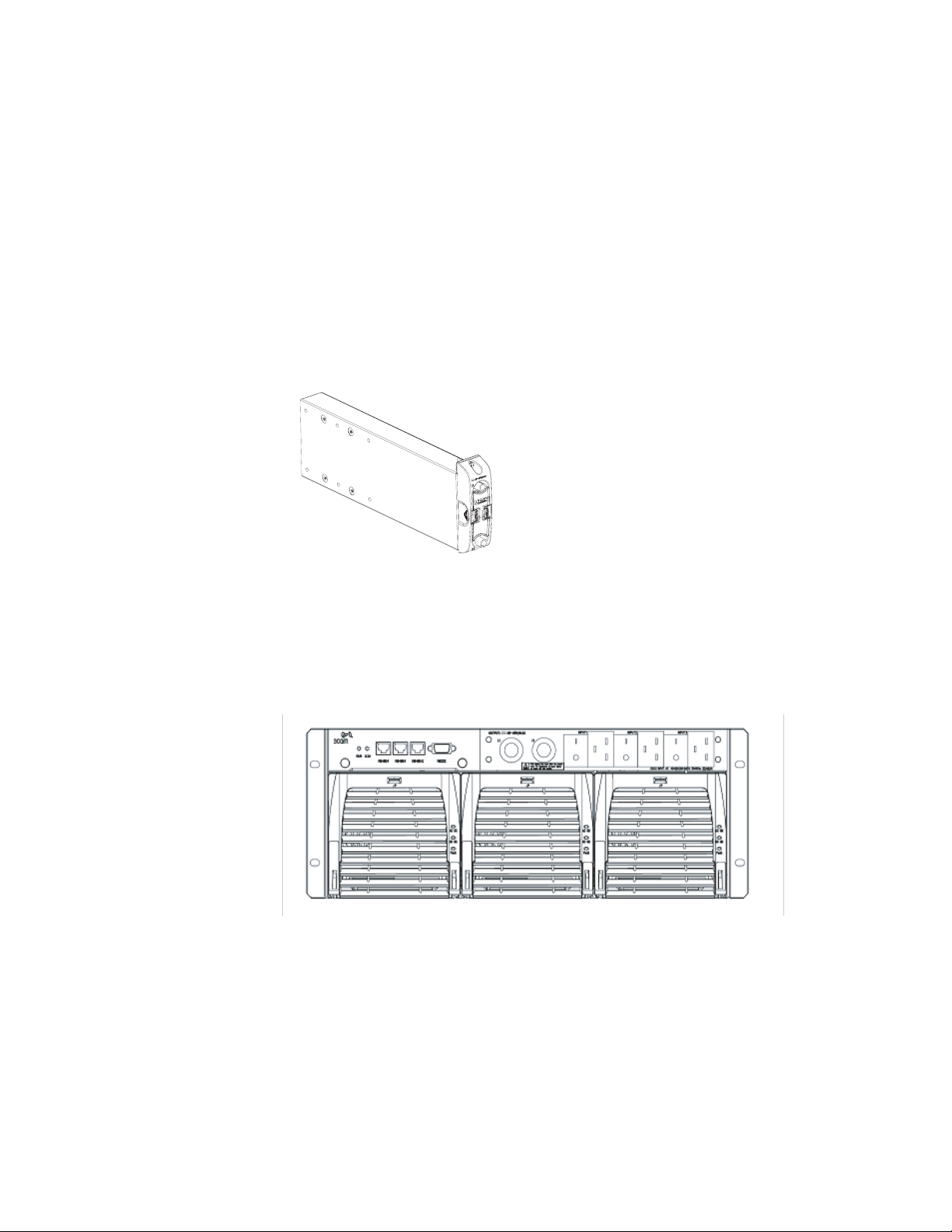
The PoE-supported Switch 8807/Switch 8810/Switch 8814 chassis has a PoE entry
area between the two power supply units. You can insert a PoE 3C17510 Switch
8800 PoE Entry Module into this area, and connect this module to a 3C17509
Switch 8800 External PoE Power Rack so as to import the output power of the
External Power Rack unit.
Figure 7 PoE entry module
PDs. It determines whether to deliver power to a newly detected PD depending
on the power it currently supplied.
n
External PoE Power Rack (3C17509)
The Switch 8800 External Power Rack is available for the Switch 8807, Switch
8810, and Switch 8814. The External Power Rack has three AC inputs and one DC
outputs.
Figure 8 Front panel of the 3C17509 Switch 8800 External Power Rack PoE power supply
Figure 8 shows its front panel.
The external PoE power system supports 2+1 redundancy and online-swapping of
PSUs.
To implement the PoE function on the Switch 8800 Family, PoE-capable interface
module is required. There are two modules are PoE-capable:
■ 3C17528 Switch 8800 48-port 10/100/1000BASE-T
■ 3C17532 Switch 8800 48-port 10/100/1000BASE-T Access
Both of these I/O Modules are PoE-capable, and will function with the addition of
a 3C17529 PoE Option (PoE DIMM Module).
Page 15

General Architecture 15
Ta bl e 2 describes typical equipment configurations and specifications of external
PoE power system.
Ta bl e 2 Typical equipment configurations and specifications of external PoE power system
Item Description
Physical dimensions (H x W x D) 177 x 486 x 320.5 mm (7.0 x 19.1 x 12.6 in.)
System controller One
Rectifier Two NP2500UAC (required) + one redundant
NP2500UAC (optional)
AC accessory Three AC inputs and switches
Three-phase AC voltage detection circuit
Input voltage range: 90 to 290 VAC; rated voltage
and current: 250 VAC, 20 A
DC accessory A single DC output, with max output current of
Max power consumption 4500 W
93 A
The external PoE power system has monitor function. It provides one system
monitoring module, one RS232 and two RS485 monitoring interfaces. The system
monitoring module reports the running information of the PSUs in the system to a
fabric through RS232 or RS485 interface and indicates alarm status by the alarm
LED (ALM). You can connect cables to the interfaces from the front as well as the
rear of the frame.
n
RS485 monitoring interface.
Ta bl e 3 LEDs of external PoE power system
LED Label Color
Input power LED AC Green ON OFF Loss of AC input power, or blown
Output power LED DC Green ON OFF No DC output from PSU
Fault LED Fault Red OFF ON Irreversible fault occurred in PSU
Running status LED RUN Green ON OFF PSU shutdown or PSU running
Alarm LED ALM Red OFF ON Loss of AC input power,
MBUS Introduction
The MBUS is a service-independent maintenance and test bus. No service traffic
goes through the MBUS. The shutdown and reset of the MBUS does not affect the
services on the switch, and faults that have occurred on modules do not affect the
MBUS.
The external PoE power system for the Switch 8800 Family only supports the
Normal
state
Abnormal
state Abnormal reason
fuse
trouble
under-voltage or over-voltage
input, under-voltage or
over-voltage output, or PSU fault
Through the MBUS, the system instructs the MBUS modules on individual cards to
power on/off the cards one by one in turn, thus prevent power surging. The MBUS
module software must support online upgrade.
Page 16
16 CHAPTER 1: PRODUCT OVERVIEW
Role and function
The MBUS system is powered by 5 V from the MBUS on the fabric. The 5 V power
on the two fabrics are redundant to each other.
Each MBUS module is attached to the MBUS, which contains two control lines:
MBUS0 and MBUS1.
Each card has an independent MBUS module, those on the fabrics are primary
MBUS modules, and those on application modules are secondary MBUS modules.
When the fabrics operate in redundancy mode, the MBUS module on the active
fabric is the active module, and the one on the standby fabric is the standby
module.
The MBUS uses a controller area network (CAN) bus as its control bus, that uses
the 1:1 hot backup and transfers control information at 1 Mbps.
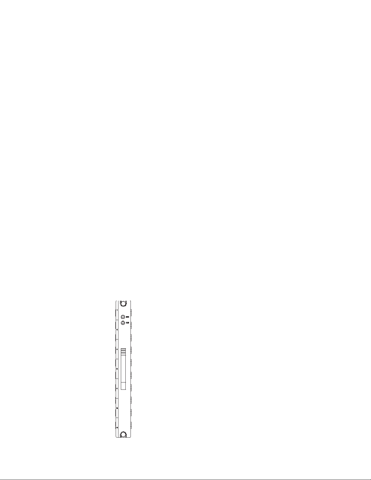
Fan Tray ■ The Switch 8807 uses one 25 W fan tray, which contains four 120 x 120 x 25.4
mm (4.7 x 4.7 x 1.0 in.) axial fan units. The fans can be governed in two
modes: fabric-controlled or temperature-controlled. They operate at -48 VDC
supplied from the backplane.
■ The Switch 8810 uses one 35 W fan tray, which contains six 120 x 120 x 25.4
mm (4.7 x 4.7 x 1.0 in.) axial fan units. The fans can be governed in two
modes: fabric-controlled or temperature-controlled. They operate at -48 VDC
supplied from the backplane.
■ The Switch 8814 uses two 25 W fan trays, each of which contains four 120 x
120 x 25.4 mm (4.7 x 4.7 x 1.0 in.) axial fan units (and totally eight for the two
fan trays). The fans can be governed in two modes: fabric-controlled or
temperature-controlled. They operate at -48 VDC supplied from the backplane.
Figure 9 Fan tray panel of the Switch 8800 Family
Page 17

Fabric Modules 17
Ta bl e 4 LEDs on fan tray panel
LED Color Status Status
RUN Green OFF The fan tray is faulty.
ON The fan tray is operating normally.
ALM Red OFF The fan tray is operating normally.
ON The fan tray is faulty.
Fabric Modules The Switch Fabric serves as the core of the Switch 8800 Family.The following fabric
models are available to the Switch 8800 Family:
■ 3C17508 - 3Com Switch 8800 360 Gbps Fabric
■ 3C17539 - 3Com Switch 8800 720 Gbps Fabric
These fabrid modules provide:
■ Route calculating and forwarding table maintenance.
■ Integrating Crossbar switching fabric to accomplish service exchange between
different boards.
■ System configuration and monitoring functions, which allows the system to
monitor other boards and upgrade/reset service board software.
360 Gbps Switch Fabric Technical specifications
This model applies to the 3C17508. See Table 5 for its specifications.
Ta bl e 5 360 Gbps Switch Fabric specifications
Item Specifications
CPU MPC755
Boot ROM 512 KB
SDRAM 512 MB (expandable to 1 GB)
Physical dimensions (W x D) 366.7 x 340 mm (14.4 x 13.4 in.)
Port One Console port, for local configuration management
Max power consumption 60 W
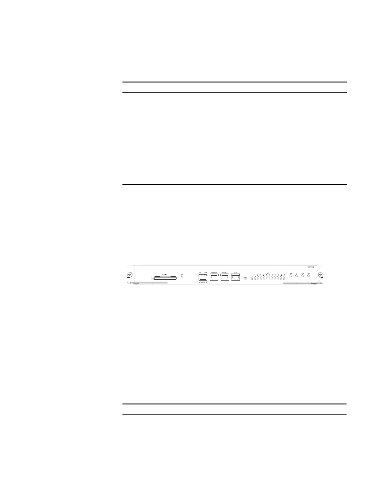
Panel
On its panel, the 360 Gbps Switch Fabric provides a CF port, CF LED (CFS),
10Base-T/100Base-TX port, RS232/485 port, Console port, AUX port, RESET
button, I/O module status LEDs, and 360 Gbps Switch Fabric status LEDs (SFS,
ACT, ALM, RUN) in turn, as shown in
One AUX port, for remote dialup configuration management
One 10Base-T/100Base-TX port, for software upgrade and
network management
One RS232/485 port, for connecting external PoE power frame
to provide the PoE function
One hot-swap-supported CF port
Figure 10.
Page 18

18 CHAPTER 1: PRODUCT OVERVIEW
Figure 10 360 Gbps Switch Fabric panel
Compact Flash (CF slot)
The 360 Gbps Switch Fabric module provides a CF slot to accommodate a
standard CF card, where you can save logging information, host version
information, alarming and other diagnostic information and conveniently upgrade
software online. The fabric ships with a CF memory card.
Management Ports
The Management 10Base-T/100Base-TX port uses an RJ-45 connector. It can
connect a background terminal for system program loading and debugging, or
connect a network management station for remote system management.
Ta bl e 6 Management 10Base-T/100Base-TX port specifications
Item Description
Connector RJ-45
Number of ports One
Rate 10 Mbps, half duplex/full duplex
100 Mbps, half duplex/full duplex
Max. transmission segment over the selected
medium
Service System program upgrade and network
100 m (328 ft.) over the category-5 twisted
pair cable (crossover cable is required).
management
The following table describes the status LEDs for the management
10Base-T/100Base-TX port.
Ta bl e 7 Status LEDs for the management 10Base-T/100Base-TX port
LED Status
LINK OFF No link is present.
ON A link is present.
ACT OFF No packets are transmitted/received on the port.
Blinking Packets are being transmitted/received on the port.
■ RS232/485 port
The RS232/485 port uses RJ-45 connector, for connecting external PoE power
frame when supported and monitoring its status.
Ta bl e 8 RS232/485 port specifications
Item Description
Connector RJ-45
Number of ports One RS 232 port and one RS485 port
Page 19

Fabric Modules 19
Table 8 RS232/485 port specifications
Item Description
Service The port for monitoring and communication with the external subsystem,
such as external PoE power supply module
■ Console port
The Console port uses an RJ-45 connector. It can be connected to a background
terminal for system debugging, maintenance, management, and host software
loading.
Ta bl e 9 Console port specifications
Item Description
Connector RJ-45
Standard Asynchronous EIA/TIA-232
Baud rate 9600 bps (default)
Transmission
segment
Service Connects a serial port of a local PC and runs terminal emulation on the
15 m (49 ft.)
PC.
n
You can choose your own baud rate for the Console port.
■ AUX port
The AUX port uses an RJ-45 connector. The port can serve as a backup port for the
Console port to connect a background terminal, or directly connect a modem
device, for remote system debugging, configuration, maintenance and
management.
Ta bl e 10 AUX port specifications
Item Description
Connector RJ-45
Standard Asynchronous EIA/TIA-232
Service Connects a serial port of a PC (through a Modem pair for a remote PC) and runs
terminal emulation on the PC.
RESET button
You can press the RESET button on the panel to reset the 360 Gbps Switch Fabric
module.
Status LEDs
■ CF status LED
You can learn the operating status of the CF card by reading the CF status LED on
the panel.
Page 20

20 CHAPTER 1: PRODUCT OVERVIEW
Ta bl e 11 CF status LED
■ Status LEDs for I/O module
The 360 Gbps Switch Fabric module has 12 pairs of LEDs to indicate the operating
status of 12 I/O module.
Ta bl e 12 Status LEDs for I/O module
LED Status
CFS ON The CF card is in position and is idle. You cannot remove the card.
Blinking The CF card is in position and reading/writing data. You cannot remove
OFF The CF card is out of position or offline (you can force the in-position CF
LED Status
RUN ON The module is faulty.
OFF The module is faulty or out of position.
Blinking (1s) The module is running normally.
Fast blinking (125 ms) The module is booting or not registered successfully.
ALM ON The module has alarms.
OFF The module has no alarms or is out of position.
0~5,
8~13
Indicate slots 0 through 5 and slots 8 through 13
the card.
card to go offline using the appropriate background command). You can
remove/insert the card.
■ Status LEDs for the 360 Gbps Switch Fabric module
You can learn the operating status of 360 Gbps Switch Fabric module by reading
the SFS, ACT, ALM and RUN LEDs on it. The following table gives a summary of
the four LEDs.
Ta bl e 13 Status LEDs for the 360 Gbps Switch Fabric module
360 Gbps Switch
Fabric LED
SFS ON The switching fabric unit is active.
RUN Green The 360 Gbps Switch Fabric module is faulty.
ALM Red The 360 Gbps Switch Fabric module has alarms.
ACT Green The 360 Gbps Switch Fabric module is active.
Status
OFF The switching fabric unit is standby.
OFF The 360 Gbps Switch Fabric module is faulty.
Green blinking The 360 Gbps Switch Fabric module runs normally.
OFF The 360 Gbps Switch Fabric module has no alarms.
OFF The 360 Gbps Switch Fabric module is standby.
Page 21
720 Gbps Switch Fabric Technical specifications
This model applies to the 3C17539. See Table 5 for its specifications.
Ta bl e 14 720 Gbps Switch Fabric specifications
Item Specifications
CPU MPC755
Boot ROM 512 KB
SDRAM 512 MB (expandable to 1 GB)
Physical dimensions (W x D) 366.7 x 340 mm (14.4 x 13.4 in.)
Port One Console port, for local configuration management
Max power consumption 110 W
Panel
On its panel, the 720 Gbps Switch Fabric provides a CF slot, CF LED (CFS),
10Base-T/100Base-TX port, RS232/485 port, Console port, AUX port, RESET
button, I/O module status LEDs, and 360 Gbps Switch Fabric status LEDs (SFS,
ACT, ALM, RUN) in turn, as shown in
card.
Fabric Modules 21
One AUX port, for remote dialup configuration management
One 10Base-T/100Base-TX port, for software upgrade and
network management
One RS232/485 port, for connecting external PoE power frame
to provide the PoE function
One hot-swap-supported CF port
Figure 10. The fabric ships with a CF memory
Figure 11 720 Gbps Switch Fabric panel
Compact Flash (CF slot)
The 720 Gbps Switch Fabric module provides a CF port to accommodate a
standard CF card, where you can save logging information, host version
information, alarming and other diagnostic information and conveniently upgrade
software online.
Management Ports
The Management 10Base-T/100Base-TX port uses an RJ-45 connector. It can
connect a background terminal for system program loading and debugging, or
connect a network management station for remote system management.
Ta bl e 15 Management 10Base-T/100Base-TX port specifications
Item Description
Connector RJ-45
Number of ports One
Rate 10 Mbps, half duplex/full duplex
100 Mbps, half duplex/full duplex
Page 22

22 CHAPTER 1: PRODUCT OVERVIEW
Table 15 Management 10Base-T/100Base-TX port specifications
The following table describes the status LEDs for the management
10Base-T/100Base-TX port.
Ta bl e 16 Status LEDs for the management 10Base-T/100Base-TX port
■ RS232/485 port
Item Description
Max. transmission segment over the selected
medium
Service System program upgrade and network
LED Status
LINK OFF No link is present.
ON A link is present.
ACT OFF No packets are transmitted/received on the port.
Blinking Packets are being transmitted/received on the port.
100 m (328 ft.) over the category-5 twisted
pair cable (crossover cable is required).
management
The RS232/485 port uses RJ-45 connector, for connecting external PoE power
frame when supported and monitoring its status.
Ta bl e 17 RS232/485 port specifications
Item Description
Connector RJ-45
Number of ports One RS 232 port and one RS485 port
Service The port for monitoring and communication with the external subsystem,
such as external PoE power supply module
■ Console port
The Console port uses an RJ-45 connector. It can be connected to a background
terminal for system debugging, maintenance, management, and host software
loading.
Ta bl e 18 Console port specifications
Item Description
Connector RJ-45
Standard Asynchronous EIA/TIA-232
Baud rate 9600 bps (default)
Transmission
segment
Service Connects a serial port of a local PC and runs terminal emulation on the
15 m (49 ft.)
PC.
n
You can choose your own baud rate for the Console port.
■ AUX port
Page 23

Fabric Modules 23
The AUX port uses an RJ-45 connector. The port can serve as a backup port for the
Console port to connect a background terminal, or directly connect a modem
device, for remote system debugging, configuration, maintenance and
management.
Ta bl e 19 AUX port specifications
Item Description
Connector RJ-45
Standard Asynchronous EIA/TIA-232
Service Connects a serial port of a PC (through a Modem pair for a remote PC) and runs
terminal emulation on the PC.
RESET button
You can press the RESET button on the panel to reset the 720 Gbps Switch Fabric
module.
Status LEDs
■ CF status LED
You can learn the operating status of the CF card by reading the CF status LED on
the panel.
Ta bl e 20 CF status LED
LED Status
CFS ON The CF card is in position and is idle. You cannot remove the card.
Blinking The CF card is in position and reading/writing data. You cannot remove
the card.
OFF The CF card is out of position or offline (you can force the in-position CF
card to go offline using the appropriate background command). You can
remove/insert the card.
■ Status LEDs for I/O module
The 720 Gbps Switch Fabric module has 12 pairs of LEDs to indicate the operating
status of 12 I/O module.
Ta bl e 21 Status LEDs for I/O module
LED Status
RUN ON The module is faulty.
OFF The module is faulty or out of position.
Blinking (1s) The module is running normally.
Fast blinking (125 ms) The module is booting or not registered successfully.
ALM ON The module has alarms.
OFF The module has no alarms or is out of position.
0~5,
8~13
Indicate slots 0 through 5 and slots 8 through 13
■ Status LEDs for the 720 Gbps Switch Fabric module
Page 24

24 CHAPTER 1: PRODUCT OVERVIEW
You can learn the operating status of 720 Gbps Switch Fabric module by reading
the SFS, ACT, ALM and RUN LEDs on it. The following table gives a summary of
the four LEDs.
Ta bl e 22 Status LEDs for the 720 Gbps Switch Fabric module
RESET button
You can press the RESET button on the panel to reset the 720 Gbps Switch Fabric.
360 Gbps Switch
Fabric LED
SFS ON The switching fabric unit is active.
RUN Green The 720 Gbps Switch Fabric module is faulty.
ALM Red The 720 Gbps Switch Fabric module has alarms.
ACT Green The 720 Gbps Switch Fabric module is active.
Status
OFF The switching fabric unit is standby.
OFF The 720 Gbps Switch Fabric module is faulty.
Green blinking The 720 Gbps Switch Fabric module runs normally.
OFF The 720 Gbps Switch Fabric module has no alarms.
OFF The 720 Gbps Switch Fabric module is standby.
Status LEDs
See the section “Status LEDs” on page 19.
System Specifications The following table summarizes the physical specifications of the Switch 8800
Family.
Ta bl e 23 Technical specifications of the Switch 8800 Family
Item Switch 8807 Switch 8810 Switch 8814
Dimensions
(H x W x D)
Weight (full load) 600 kg (143 lb) 80 kg (176 lb) 100 kg (220 lb)
Max power
consumption
Switching
capacity (see
Note 1)
Number of
VLANs
Maximum MAC
address table size
Forwarding table
entries
Number of fabric
slots
486 x 436 x 450 mm
(19.1 x 17.2 x 17.7
in.)
1200 W 2000 W 2000 W
Fab360: 600 Gbps
(see Note 2)
4 K
14 K/per module, total 14 K x number of modules
See Note 3
128 K/256 K
2 2 2
619 x 436 x 450 mm
(24.4 x 17.2 x 17.7
in.)
Fab360: 480Gbps
Fab720: 960Gbps
753 x 436 x 450 mm
(29.6 x 17.2 x 17.7 in.)
Fab360: 720Gbps
Fab720: 1440Gbps
Page 25

Software Features 25
Table 23 Technical specifications of the Switch 8800 Family
Item Switch 8807 Switch 8810 Switch 8814
fabric module
type
Number of I/O
module slots
User interface 10/100/1000BASE-TX RJ45
Operating
temperature
Operating
humidity
(noncondensing)
Storage
temperature
Storage humidity 10% to 90 %
360 Gbps Fabric 360 Gbps Switch
Fabric
720 Gbps Switch
Fabric
5 8 12
1000BASE-X (SFP)
10BASE-X (XENPAK)
10BASE-X (XFP)
0 to 40C (32 to 104F)
10% to 90 %
-10 to 70C (14 to 158F)
360 Gbps Switch Fabric
720 Gbps Switch Fabric
n
load-sharing fabrics.
Note 2: The 7-slot has additional backplane traces per slot compared to the
14-slot and the 10- slot chassis. The additional traces enable higher capacity per
slot using the 360G Fabric compared to the 10-slot and 14-slot chassis.
Note 3: See the Switch 8800 Configuration Guide for rules and limitations.
Software Features The software of the Switch 8800 Family uses fully distributed processing and runs
on 3Com network operating system Comware. The following table summaries the
supported software features.
Ta bl e 24 Software features of the Switch 8800 Family
Item Description
VLAN IEEE 802.1Q-compliant VLAN
Port-based, protocol-based (8 groups), IP subnet-based
VLAN division
GARP VLAN registration protocol (GVRP)
Super VLAN
Isolate user VLAN
Guest VLAN
Dynamic VLAN
STP IEEE 802.1d/IEEE 802.1w/IEEE 802.1s-compliant
spanning tree protocol (STP)/rapid STP (RSTP)/multiple
STP (MSTP)
Note 1: The switching capacity in the above table is calculated based on two
Page 26

26 CHAPTER 1: PRODUCT OVERVIEW
Table 24 Software features of the Switch 8800 Family
Item Description
Flow control IEEE 802.3x flow control (full duplex)
Back pressure flow control (half duplex)
Broadcast/multicast suppression Supported
Multicast Internet group management protocol (IGMP) snooping
IGMP
Internet group management protocol (IGMP) v2
Protocol-independent multicast-dense mode (PIM-DM)
Protocol-independent multicast-sparse mode (PIM-SM)
Multicast source discovery protocol (MSDP)
Multiprotocol border gateway protocol (MBGP)
Any-RP
IP routing Static routing
Routing information protocol (RIP) v1/v2
Open shortest path first (OSPF) v2
Border gateway protocol (BGP)
Intermediate system-to-intermediate system (IS-IS)
Equal cost route forwarding
Routing policy
Policy routing
OSPF/IS-IS/BGP graceful restart (GR)
Link aggregation Aggregation across cards
LACP
DHCP DHCP server
DHCP relay
DHCP Option 82
Mirroring Port-based mirroring
Multiprotocol Label Switching (MPLS) L3 MPLS VPN, inter-domain MPLS VPN, hierarchy of PE
(HoPE), CE dual homing, MCE, multi-role host
VLL: Martini, Kompella, and CCC mode
VPLS
QoS Traffic classification based on port, MAC address,
VLAN, IP address, IP priority, TCP/UDP port number,
DSCP priority, Type of service (ToS) priority, class of
service (CoS) priority, etc.
Traffic monitoring, with granularity of 8 Kbps
Traffic shaping
Priority mark/remark
Queue scheduling: strict priority (SP), weighted round
Robin (WRR) and SP + WRR <par
8 priority queues for each port
Congestion avoidance algorithms: tail drop (TD) and
weighted random early detection (WRED)
Page 27

Software Features 27
Table 24 Software features of the Switch 8800 Family
Item Description
Security Hierarchical user management and password
protection
Password control
802.1x authentication
Packet filtering
Port-based broadcast frame suppression, speed
calculation in bytes or packets
Protection from attacks by virus packets, such as DOS
attacks
AAA/RADIUS/HWTACACS
SSH 2.0 (security shell)
Firewall
IPsec
Education network accounting
QinQ Port VLAN VPN
Flexible QinQ
Network Monitoring feature NetFlow v5/v8/v9
Management and maintenance Configuration through the command line interface
Loading and upgrade Loading and upgrade using the XModem protocol
(CLI)
Configuration through the Console/AUX port
Telnet configuration/maintenance through Ethernet
ports
Modem dialup configuration/maintenance through
AUX port
SNMP management, with the 3Com network
management application, RMON (remote monitoring),
and 1/2/3/9 groups of MIBs.
System logging
Hierarchical alarming
Debugging information output
ping and tracert commands
NQA
Loading and upgrade using FTP/TFTP
Loading of BootROM and host software
n
All specifications are subject to changes without notice. For up-to-date
information, please contact 3Com marketing or technical support personnel.
Page 28

28 CHAPTER 1: PRODUCT OVERVIEW
Page 29

I/O AND APPLICATION MODULES
2
Overview The Switch 8800 Family are modular switches that are designed following industry
standards. The following I/O modules are available to the Switch 8800 Family:
Ta bl e 25 I/O modules available to the Switch 8800 Family
I/O module User interface
3C17511 1-port 10GBASE-X (XENPAK)
3C17512 2-port 10GBASE-X (XFP)
3C17513 12-port 1000BASE-X (SFP)
3C17514 24-port 1000BASE-X (SFP)
3C17516 24-port 10/100/1000BASE-T (RJ-45)
3C17525 1-port 10GBASE-X (XENPAK) Advanced
3C17526 4-port 10GBASE-X (XFP)
3C17527 2-port 10GBASE-X (XFP) Advanced
3C17528 48-port 10/100/1000 BASE-T (RJ-45)
3C17530 24-port 1000BASE-X (SFP) Advanced
3C17531 24-port 10/100/1000BASE-T (RJ-45) Advanced
3C17532 48-port 10/100/1000BASE-T (RJ-45) Access
3C17533 24-port 1000BASE-X (SFP) IPv6 Module
3C17534 24-port 10/100/1000BASE-T (RJ-45) IPv6 Module
3C17536 4-port 10GBASE-X (XFP) QUAD IPv6
3C17538 48-port 1000BASE-X (SFP) IPv6
3C17542 Network Monitoring Module
3C17546 Firewall Module
3CR1754766 IPsec Module
3C17548 Virtual Private LAN Service (VPLS)
3C17511 1-port 10GBASE-X (XENPAK)
Specifications This section provides specifications for the 1-port 10GBASE-X (XENPAK) 3C17511
module.
Ta bl e 26 3C17511 module specifications
Item Specification
CPU MPC8245
Boot ROM 512 KB
Page 30
30 CHAPTER 2: I/O AND APPLICATION MODULES
Table 26 3C17511 module specifications
Item Specification
SDRAM 128 MB/256 MB
Physical dimensions (W x D) 366.7 x 340 mm(14.4 x 13.4 in.)
Max power consumption 45 W
Number of ports One
Connector XENPAK/SC
Rate 10 Gbps
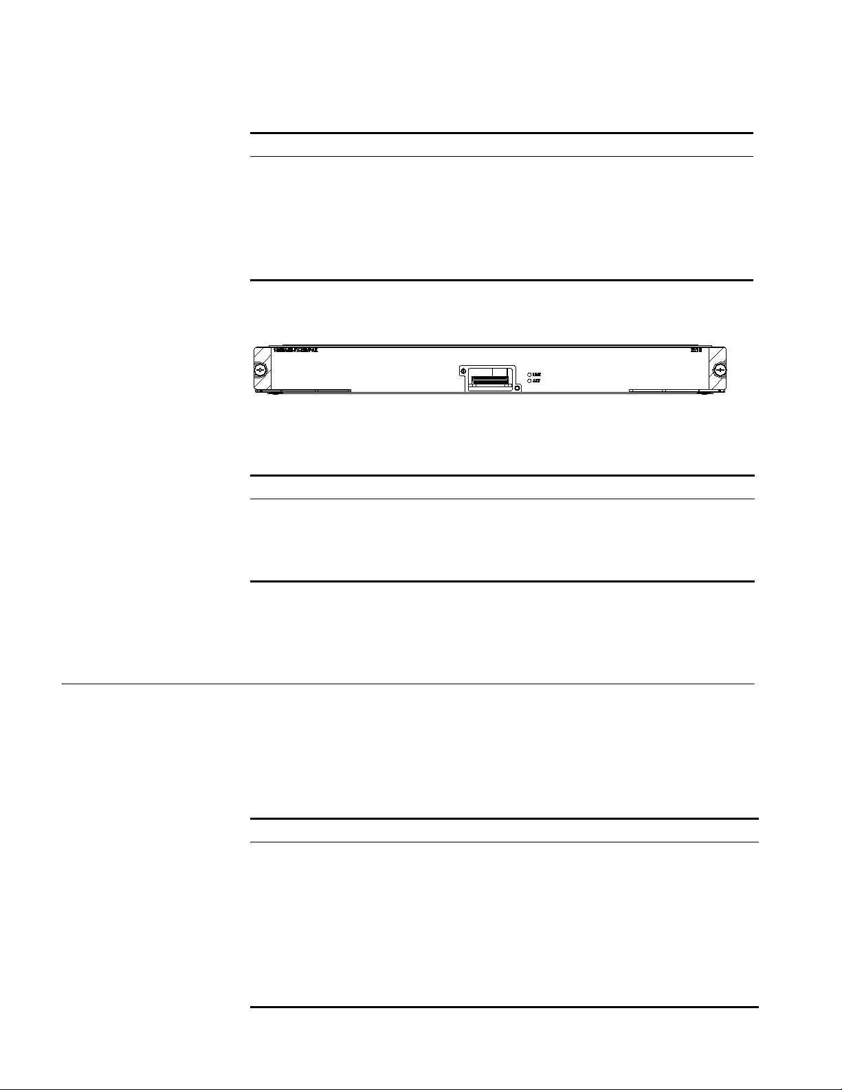
Panel and LEDs Figure 12 3C17511 module panel
The 3C17511 module has two port LEDs for the 10GE port on its panel.
Matching Cable See Table 64 on page 45 for the XENPAK optical modules available to the 10GE
3C17512 2-port 10GBASE-X (XFP) Module
Specifications The 3C17512 modules provide two 10GBASE-X XFP/LC ports.
Ta bl e 27 Port LEDs on the 3C17511 module
LED Status Meaning
LINK OFF No link is present.
Green ON A link is present.
ACT OFF No packets are transmitted/received on the port.
Orange blinking Packets are being transmitted/received on the port.
XENPAK/SC optical/electrical port on the 3C17511 module and their matching
cable types, which you can select as required.
This section provides specifications for the 2-port 10GBASE-X (XFP) module
(3C17512).
Ta bl e 28 3C17512 module specifications
Item Specification
CPU MPC8245
Boot ROM 512 KB
SDRAM 128 MB/256MB
Physical dimensions (W x D) 366.7 x 340 mm (14.4 x 13.4 in.)
Max power consumption 87 W
Number of ports Two
Connector XFP
Rate 10 Gbps
Page 31
3C17513 12-port 1000BASE-X (SFP) Module 31
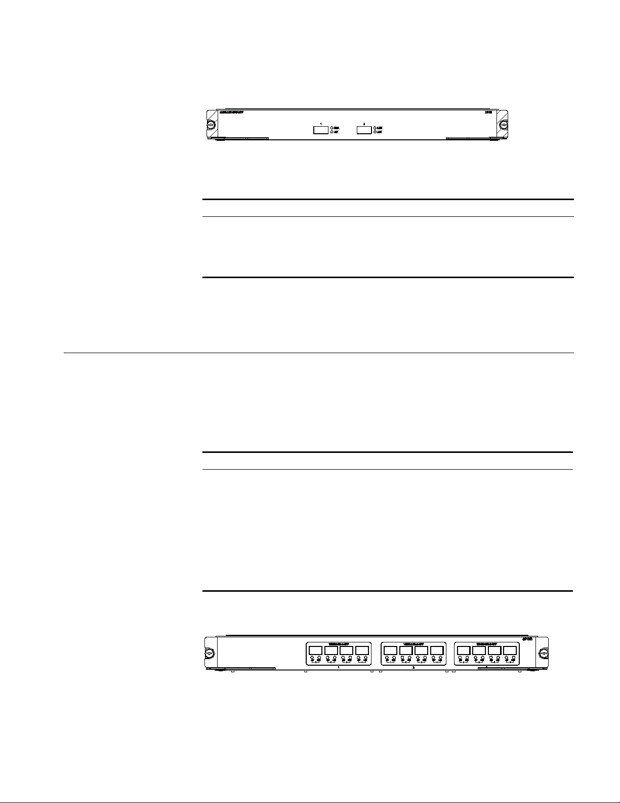
Panel and LEDs Figure 13 3C17512 module panel
The 3C17512 module has two LEDs for each optical port on its panel.
Ta bl e 29 1000 Mbps optical port LEDs on the 3C17512 module
LED Status Meaning
LINK OFF No link is present.
Green A link is present.
ACT OFF No packets are transmitted/received on the port.
Orange blinking Packets are being transmitted/received on the port.
Matching Cable See Table 64 on page 45 for the XFP optical modules available for the 10 Gbps XFP
optical ports on the 3C17512 module and their matching cable types, which you
can select as required.
3C17513 12-port 1000BASE-X (SFP) Module
Specifications The 3C17513 module provides 12 x 1000 Mbps SFP/LC optical ports.
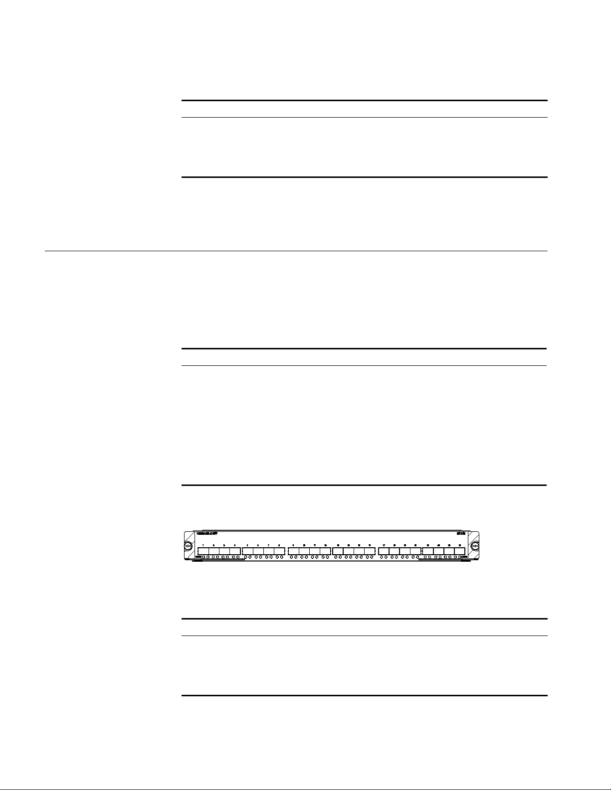
Panel and LEDs Figure 14 3C17513 module panel
This section provides specifications for the 12-port 1000BASE-X (SFP) module
(3C17513)
Ta bl e 30 3C17513 module specifications
Item Specification
CPU MPC8245
Boot ROM 512 KB
SDRAM 128 MB
Physical dimensions (W x D) 366.7 x 340 mm (14.4 x 13.4 in.)
Max power consumption 55 W
Number of ports 12
Connector SFP/LC
Rate 1.25 Gbps
The 3C17513 module has two LEDs for each port on its panel.
Page 32
32 CHAPTER 2: I/O AND APPLICATION MODULES
Ta bl e 31 Port LEDs on the 3C17513 module
LED Status Meaning
LINK OFF No link is present.
Green A link is present.
ACT OFF No packets are transmitted/received on the port.
Orange blinking Packets are being transmitted/received on the port.
Matching Cable See Table 64 on page 45 for the SFP optical modules available to the SFP optical
ports on the 3C17513 module and their matching cable types, which you can
select as required.
3C17514 24-port 1000BASE-X (SFP) Module
Specifications The 3C17514 module provides 24 1000BASE-X (SFP) ports.
Panel and LEDs Figure 15 3C17514 module panel
This section provides specifications for the 24-port 1000BASE-X (SFP) module
(3C17514).
Ta bl e 32 3C17514 module specifications
Item Specification
CPU MPC8245
Boot ROM 512 KB
SDRAM 128 MB/256 MB
Physical dimensions (W x D) 366.7 x 340 mm (14.4 x 13.4 in.)
Max power consumption 100 W
Number of ports 24
Connector SFP/LC
Rate 1.25 Gbps
The 3C17514 module has two LEDs for each 1000 Mbps optical port on its panel.
Ta bl e 33 Port LEDs on the 3C17514 module
LED Status Meaning
LINK OFF No link is present.
Green A link is present.
ACT OFF No packets are transmitted/received on the port.
Orange blinking Packets are being transmitted/received on the port.
Matching Cable You can select appropriate SFP optical modules for the 1000 Mbps SFP optical
ports on the 3C17514 module according to your needs. For description of SFP
Page 33
3C17516 24-port 10/100/1000BASE-T Module 33
optical modules available to the SFP optical ports and their matching cable types,
Ta bl e 64 on page 45.
see
3C17516 24-port 10/100/1000BASE-T Module
Specifications The 3C17516 module provides 24 10/100/1000BASE-T (RJ45) ports.
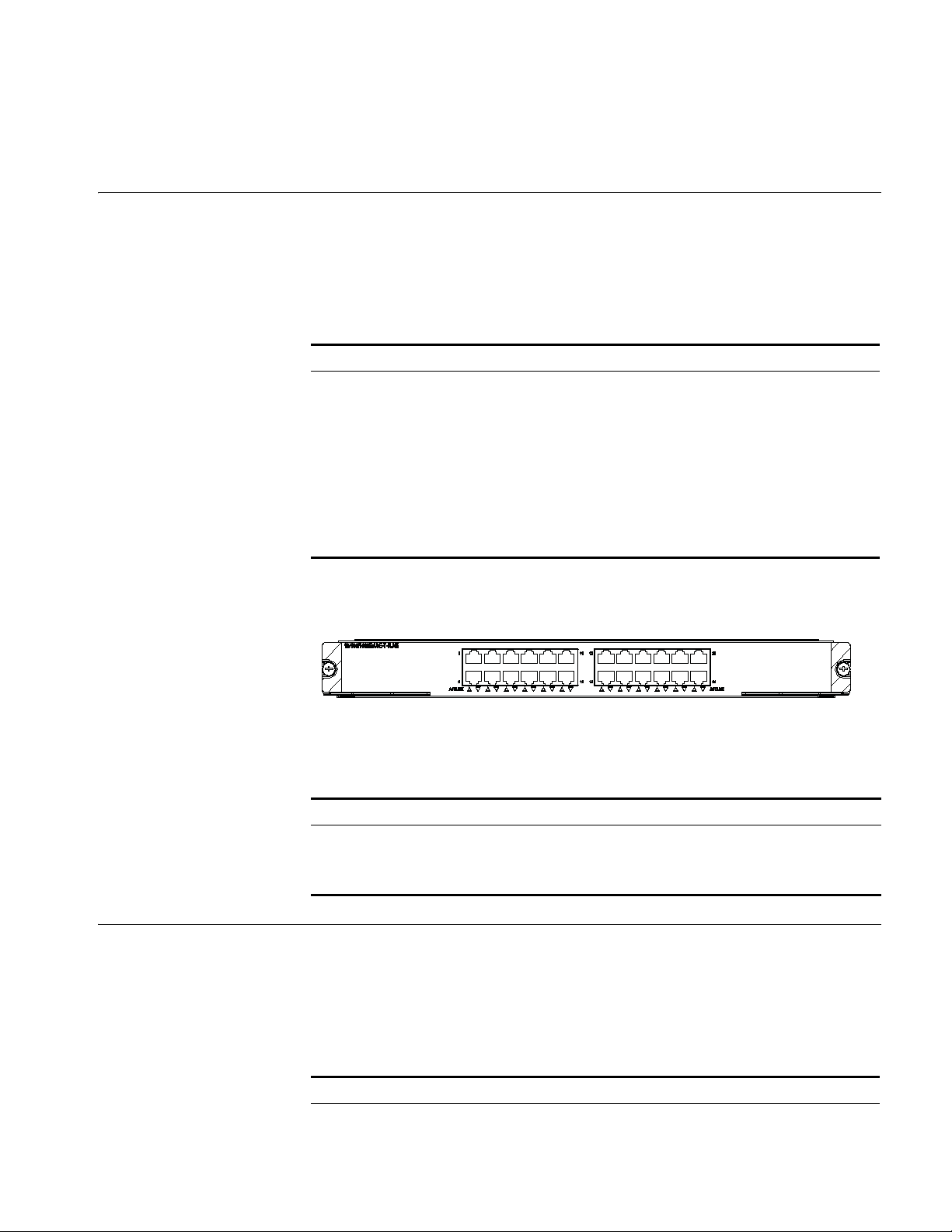
Panel and LEDs Figure 16 3C17516 module panel
This section provides specifications for the 24-port 10/100/1000BASE-T module
(3C17516).
Ta bl e 34 3C17516 module specifications
Item Specification
CPU MPC8245
Boot ROM 512 KB
SDRAM 128 MB/256 MB
Physical dimensions (W x D) 366.7 x 340 mm (14.4 x 13.4 in.)
Max power consumption 110 W
Number of ports 24
Connector RJ-45
Rate 10/100/1000 Mbps
3C17525 1-port 10GBASE-X Advanced (XENPAK) Module
Specifications The 3C17525 module provides one 10GE XENPAK/SC optical/electrical port.
The 3C17516 module has one LED for each port on its panel.
Ta bl e 35 Port LEDs on the 3C17516 module
LED Status Meaning
LINK/ACT ON No link is present.
OFF A link is present.
Blinking Packets are being transmitted/received on the port.
This section provides specifications for the 1-port 10GBASE-X (XENPAK) Advanced
module (3C17525).
Ta bl e 36 3C17511 module specifications
Item Specification
CPU MPC8245
Boot ROM 512 KB
Page 34
34 CHAPTER 2: I/O AND APPLICATION MODULES
Table 36 3C17511 module specifications
Item Specification
SDRAM 128 MB/256 MB
Physical dimensions (W x D) 366.7 x 340 mm(14.4 x 13.4 in.)
Max power consumption 45 W
Number of ports One
Connector XENPAK/SC
Rate 10 Gbps
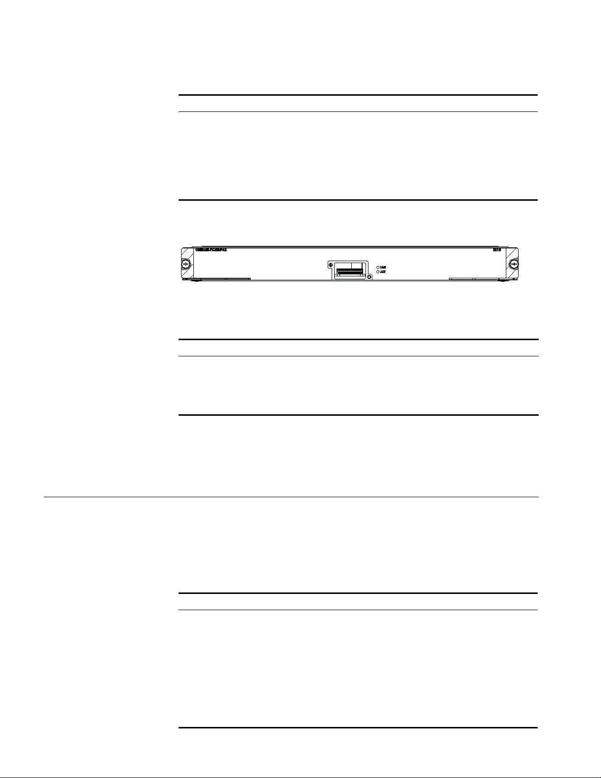
Panel and LEDs Figure 17 3C17525 module panel
The 3C17525 module has two port LEDs for the 10GE port on its panel.
Matching Cable See Table 64 on page 45 for the XENPAK optical modules available for the 10GE
3C17526 4-port 10GBASE-X (XFP) Module
Specifications The 3C17526 module provides four 10GBASE-X (XFP) ports.
Ta bl e 37 Port LEDs on the 3C17525 module
LED Status Meaning
LINK OFF No link is present.
Green ON A link is present.
ACT OFF No packets are transmitted/received on the port.
Orange blinking Packets are being transmitted/received on the port.
XENPAK/SC optical/electrical port on the 3C17525 module and their matching
cable types, which you can select as required.
This section provides specifications for the 4-port 10GBASE-X (XFP) module
(3C17526).
Ta bl e 38 3C17526 module specifications
Item Specification
CPU MPC8245
Boot ROM 512 KB
SDRAM 128 MB/256 MB
Physical dimensions (W x D) 366.7 x 340 mm (14.4 x 13.4 in.)
Number of ports Four
Max power consumption 160 W
Connector XFP
Rate 10 Gbps
Page 35
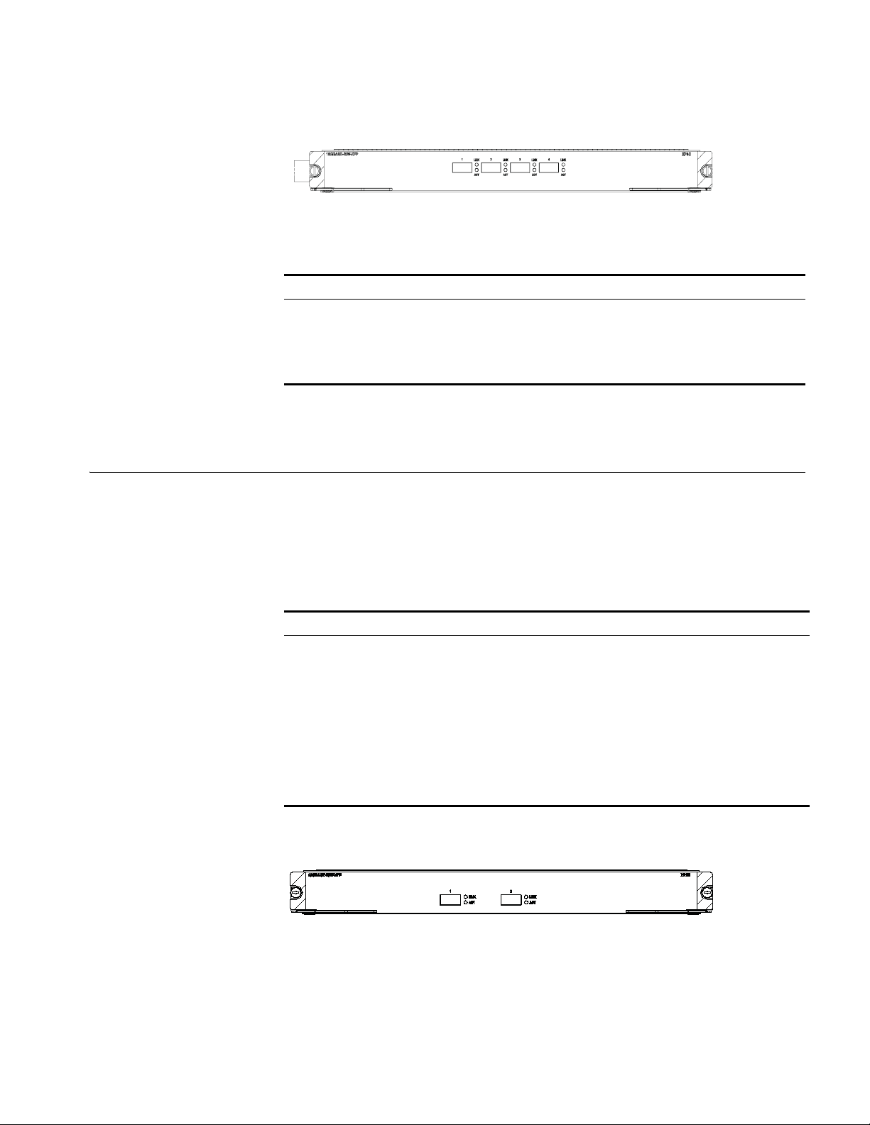
3C17527 2-port 10GBASE-X (XFP) Advanced Module 35
Panel and LEDs Figure 18 3C17526 module panel
The 3C17526 module has two LEDs for each optical port on its panel.
Ta bl e 39 1000 Mbps optical port LEDs on the 3C17526 module
LED Status Meaning
LINK OFF No link is present.
Green A link is present.
ACT OFF No packets are transmitted/received on the port.
Orange blinking Packets are being transmitted/received on the port.
Matching Cable For details about XFP optical modules available to the XFP optical ports on the
3C17526 module and their matching cable types, see
Ta bl e 64 on page 45.
3C17527 2-port 10GBASE-X (XFP) Advanced Module
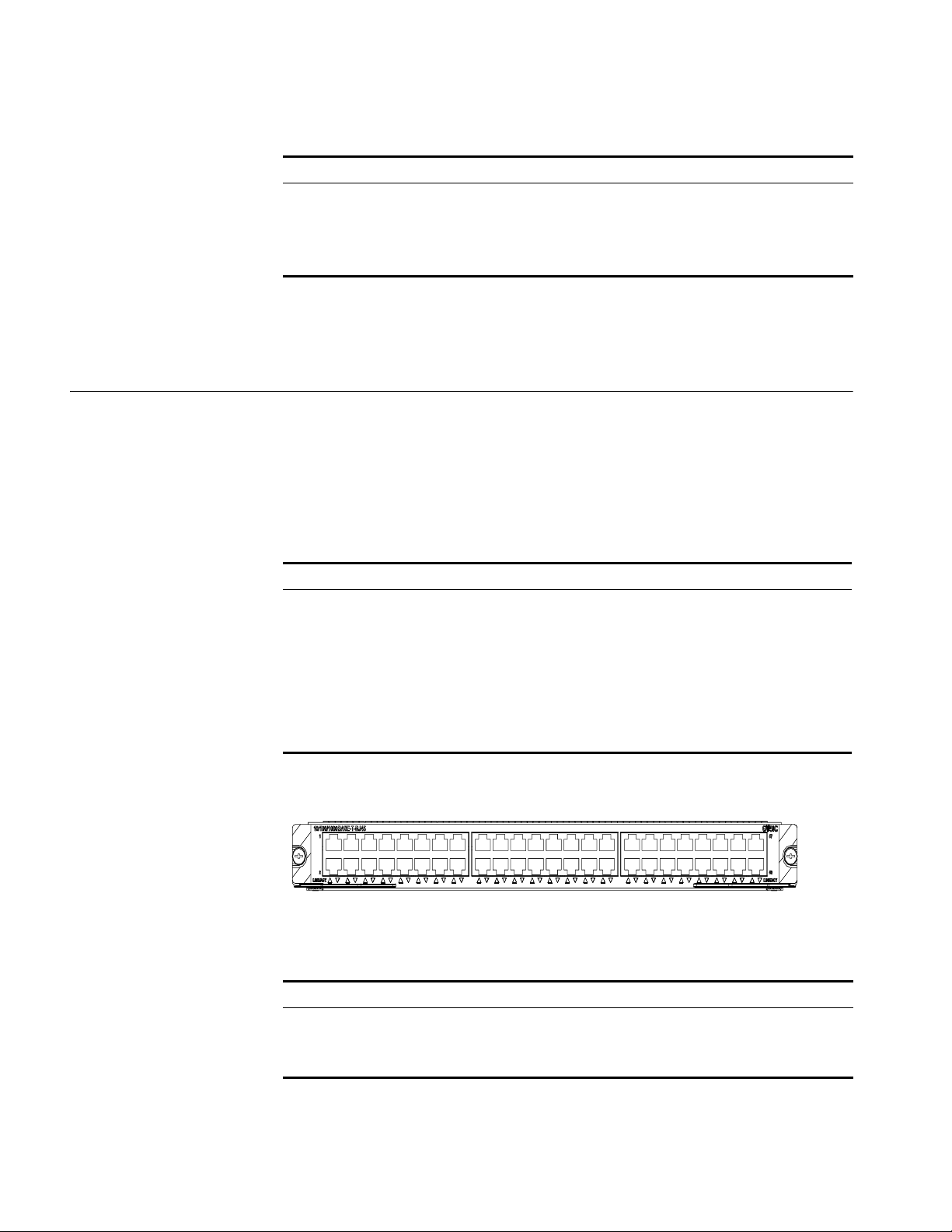
Specifications The 3C17527 module provide two 10GBASE-X XFP/LC ports.
Panel and LEDs Figure 19 3C17527 module panel
This section provides specifications for the 2-port 10GBASE-X (XFP) Advanced
module (3C17527).
Ta bl e 40 3C17527 module specifications
Item Specification
CPU MPC8245
Boot ROM 512 KB
SDRAM 128 MB/256MB
Physical dimensions (W x D) 366.7 x 340 mm (14.4 x 13.4 in.)
Max power consumption 87 W
Number of ports Two
Connector XFP
Rate 10 Gbps
The 3C17527 module has two LEDs for each optical port on its panel.
Page 36
36 CHAPTER 2: I/O AND APPLICATION MODULES
Ta bl e 41 1000 Mbps optical port LEDs on the 3C17527 module
LED Status Meaning
LINK OFF No link is present.
Green A link is present.
ACT OFF No packets are transmitted/received on the port.
Orange blinking Packets are being transmitted/received on the port.
Matching Cable See Table 64 on page 45 for the XFP optical modules that are available for the 10
Gbps XFP optical ports on the 3C17527 module and their matching cable types,
which you can select as required.
3C17528 48port 10/100/1000 BASE-T (RJ-45) Module
Specifications The 3C17528 module provides 48 10/100/1000 BASE-T auto-sensing PoE-capable
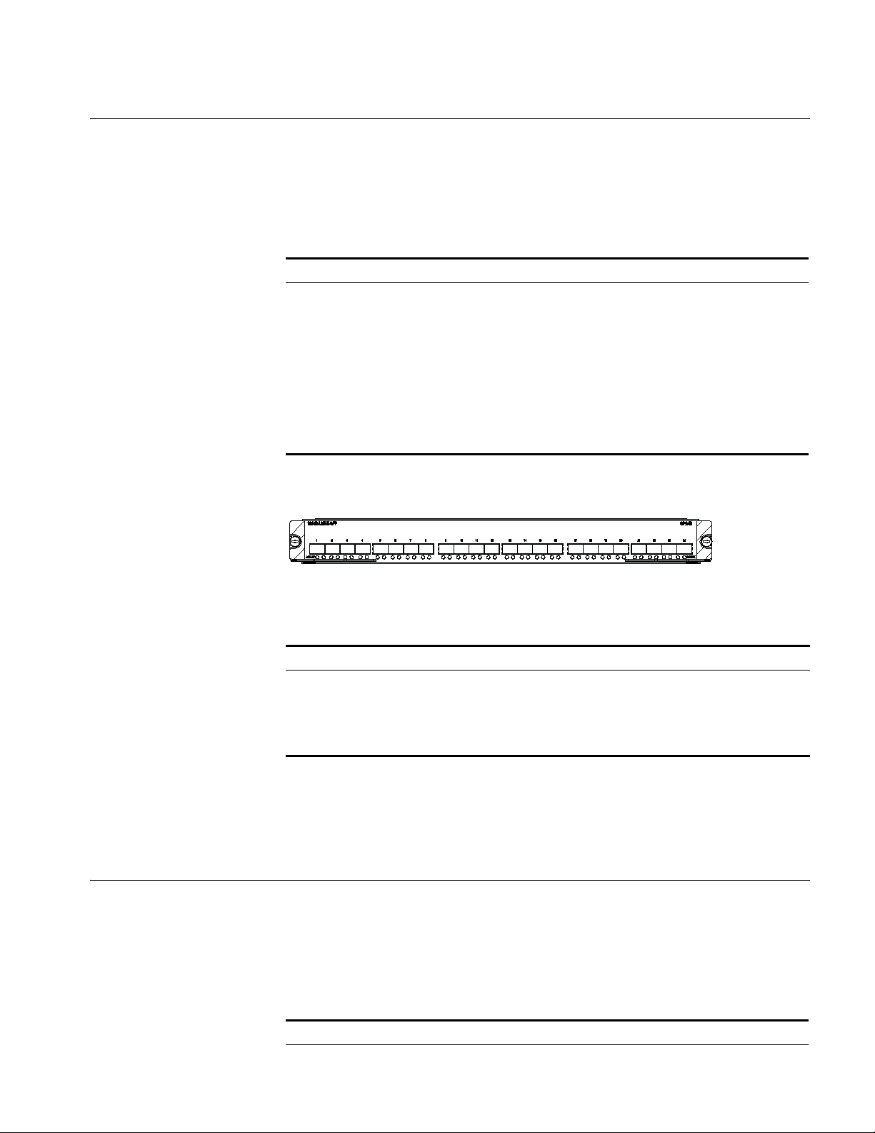
Panel and LEDs Figure 20 3C17528 module panel
This section provides specifications for the 48-port 10/100/1000 BASE-T (RJ-45)
module (3C17528).
RJ-45 ports.
Ta bl e 42 3C17528 module specifications
Item Specification
CPU MPC8245
BootROM 512 KB
SDRAM 128 MB
Physical dimensions (W x D) 366.7 x 340 mm (14.4 x 13.4 in.)
Number of ports 48
Connector RJ-45
Rate 10/100/1000 Mbps
The 3C17528 module has one LED for each port on its panel.
Ta bl e 43 1000 Mbps electrical port LEDs on the 3C17528 module
LED Status Meaning
LINK/ACT ON A link is present.
OFF No link is present.
Blinking Packets are being transmitted/received on the port.
Page 37
3C17530 24-port 1000BASE-X (SFP) Advanced Module 37
3C17530 24-port 1000BASE-X (SFP) Advanced Module
Specifications The 3C17530 Advanced Module provide 24 1000BASE-X (SFP) ports.
Panel and LEDs Figure 21 3C17530 module panel
This section provides specifications for the 24-port 1000BASE-X (SFP) Advanced
module (3C17530).
Ta bl e 44 3C17530 module specifications
Item Specification
CPU MPC8245
Boot ROM 512 KB
SDRAM 128 MB/256 MB
Physical dimensions (W x D) 366.7 x 340 mm (14.4 x 13.4 in.)
Max power consumption 100 W
Number of ports 24
Connector SFP/LC
Rate 1.25 Gbps
Matching Cable You can select appropriate SFP optical modules for the 1000 Mbps SFP optical
3C17531 24-port 10/100/1000BASE-T Advanced Module
Specifications The 3C17531 module provides 24 10/100/1000BASE-T (RJ45) ports.
The 3C17530 module has two LEDs for each 1000 Mbps optical port on its panel.
Ta bl e 45 Port LEDs on the 3C17530 module
LED Status Meaning
LINK OFF No link is present.
Green A link is present.
ACT OFF No packets are transmitted/received on the port.
Orange blinking Packets are being transmitted/received on the port.
ports on the
3C17530 module according to your needs. For a description of SFP the
optical modules available for the SFP optical ports and their matching cable types,
Ta bl e 64 on page 45.
see
This section provides specifications for the 24-port 10/100/1000BASE-T module
(3C17531).
Ta bl e 46 3C17531 module specifications
Item Specification
CPU MPC8245
Page 38
38 CHAPTER 2: I/O AND APPLICATION MODULES
Table 46 3C17531 module specifications
Item Specification
Boot ROM 512 KB
SDRAM 128 MB/256 MB
Physical dimensions (W x D) 366.7 x 340 mm (14.4 x 13.4 in.)
Max power consumption 110 W
Number of ports 24
Connector RJ-45
Rate 10/100/1000 Mbps
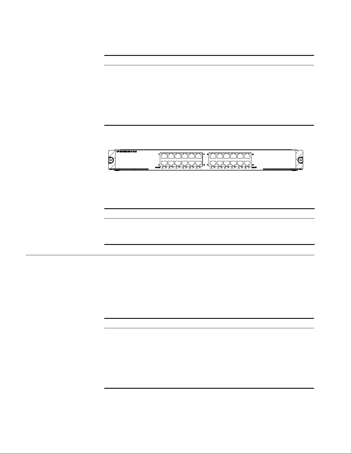
Panel and LEDs Figure 22 3C17531 module panel
The 3C17531 module has one LED for each port on its panel.
3C17532 48-port 10/100/1000 BASE-T (RJ-45) Access Module
Specifications The 3C17532 module provides 48 10/100/1000 BASE-T auto-sensing PoE-capable
Ta bl e 47 Port LEDs on the 3C17531 module
LED Status Meaning
LINK/ACT ON No link is present.
OFF A link is present.
Blinking Packets are being transmitted/received on the port.
This section provides specifications for the 48-port 10/100/1000 BASE-T (RJ-45)
Access module (3C17532).
RJ-45 ports.
Ta bl e 48 3C17532 module specifications
Item Specification
CPU MPC8245
BootROM 512 KB
SDRAM 128 MB
Physical dimensions (W x D) 366.7 x 340 mm (14.4 x 13.4 in.)
Number of ports 48
Connector RJ-45
Rate 10/100/1000 Mbps
Page 39
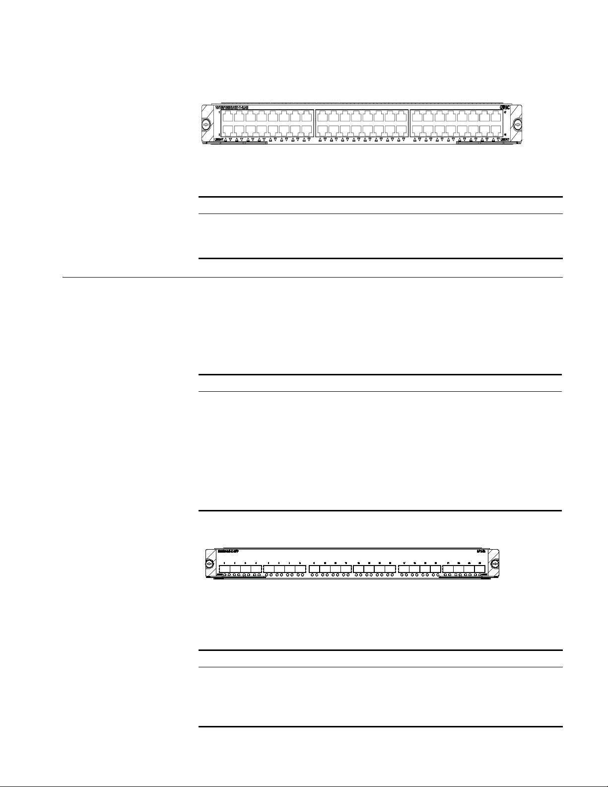
Panel and LEDs Figure 23 3C17532 module panel
The 3C17532 module has one LED for each port on their panel.
Ta bl e 49 1000 Mbps electrical port LEDs on the 3C17532 module
LED Status Meaning
LINK/ACT ON A link is present.
OFF No link is present.
Blinking Packets are being transmitted/received on the port.
3C17533 24-port 1000BASE-X (SFP) IPv6 Module 39
3C17533 24-port 1000BASE-X (SFP) IPv6 Module
Specifications The 3C17533 IPv6 module provides 24 1000BASE-X (SFP) ports.
Panel and LEDs Figure 24 3C17533 module panel.
This section provides specifications for the 24-port 1000BASE-X (SFP) IPv6 module
(3C17533).
Ta bl e 50 3C17533 module specifications
Item Specification
CPU MPC8245
Boot ROM 512 KB
SDRAM 128 MB/256 MB
Physical dimensions (W x D) 366.7 x 340 mm (14.4 x 13.4 in.)
Max power consumption 100 W
Number of ports 24
Connector SFP/LC
Rate 1.25 Gbps
The 3C17533 module has two LEDs for each 1000 Mbps optical port on its panel.
Ta bl e 51 Port LEDs on the 3C17533 module
LED Status Meaning
LINK OFF No link is present.
Green A link is present.
ACT OFF No packets are transmitted/received on the port.
Orange blinking Packets are being transmitted/received on the port.
Page 40
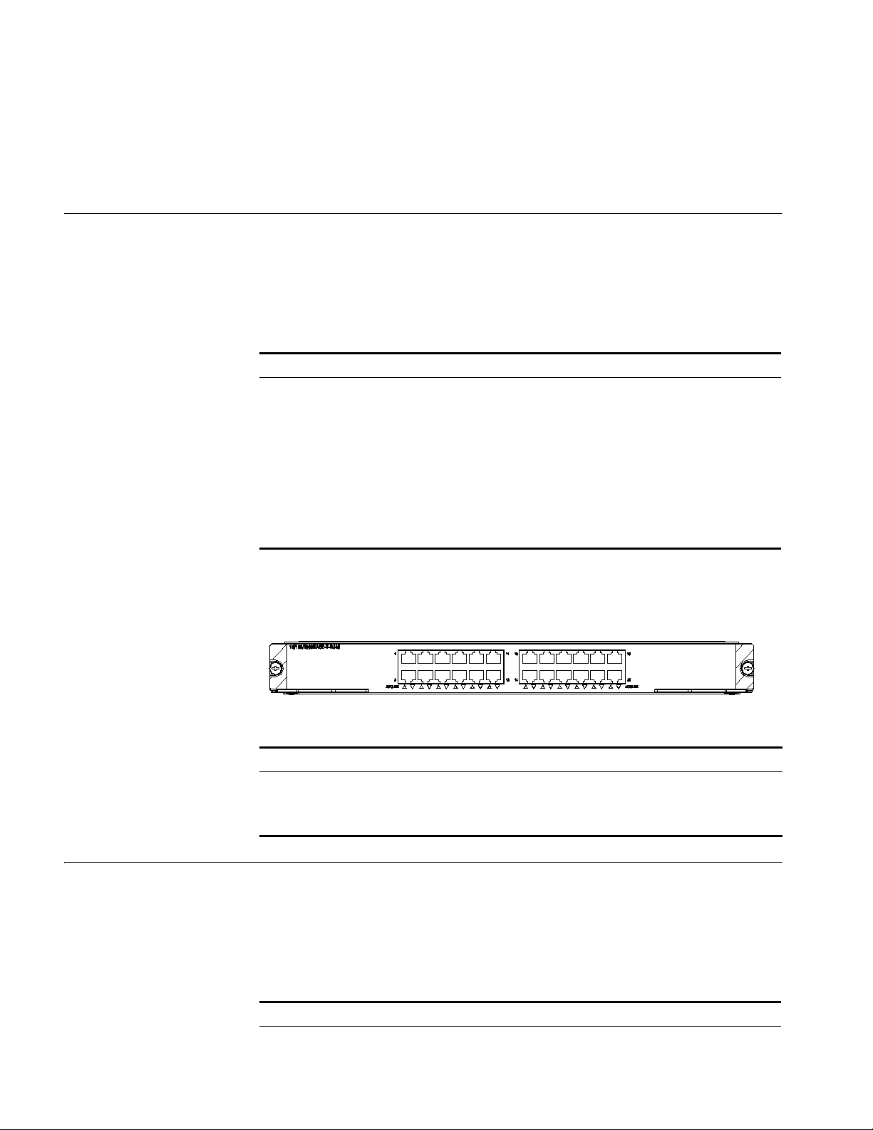
40 CHAPTER 2: I/O AND APPLICATION MODULES
Matching Cable You can select appropriate SFP optical modules for the 1000 Mbps SFP optical
ports on the
optical modules available for the SFP optical ports and their matching cable types,
Ta bl e 64 on page 45.
see
3C17533 module according to your needs. For a description of SFP the
3C17534 24-port 10/100/1000BASE-T IPv6 Module
Specifications The 3C17534 module provides 24 10/100/1000BASE-T (RJ45) ports.
Panel and LEDs The 3C17534 module has one LED for each port on its panel.
This section provides specifications for the 24-port 10/100/1000BASE-T IPv6
module (3C17534).
Ta bl e 52 3C17534 module specifications
Item Specification
CPU MPC8245
Boot ROM 512 KB
SDRAM 128 MB/256 MB
Physical dimensions (W x D) 366.7 x 340 mm (14.4 x 13.4 in.)
Max power consumption 110 W
Number of ports 24
Connector RJ-45
Rate 10/100/1000 Mbps
Figure 25 3C17534 module panel
3C17536 4-port 10GBASE-X (XFP) QUAD IPv6 Module
Specifications The 3C17536 module provides four 10GBASE-X (XFP) ports.
Ta bl e 53 Port LEDs on the 3C17534 module
LED Status Meaning
LINK/ACT ON No link is present.
OFF A link is present.
Blinking Packets are being transmitted/received on the port.
This section provides specifications for the 4-port 10GBASE-X (XFP) QUAD IPv6
module (3C17536).
Ta bl e 54 3C17536 module specifications
Item Specification
CPU MPC8245
Page 41
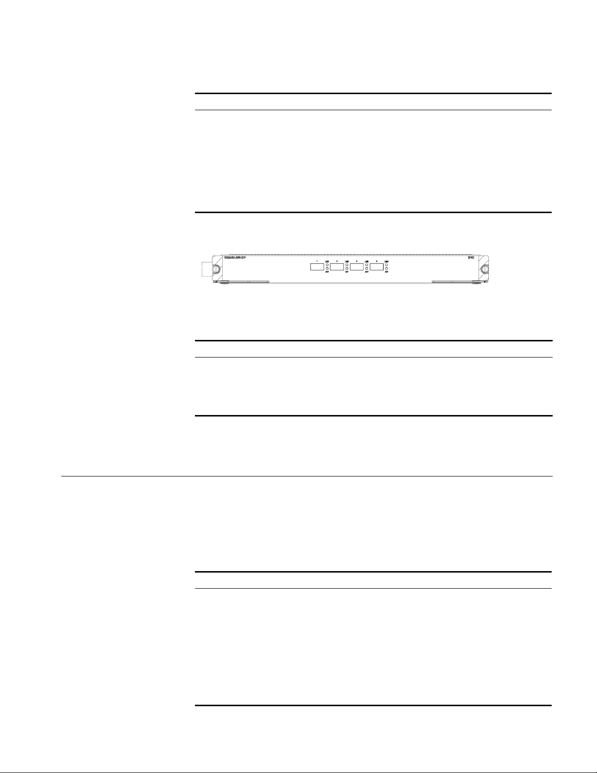
Table 54 3C17536 module specifications
Item Specification
Boot ROM 512 KB
SDRAM 128 MB/256 MB
Physical dimensions (W x D) 366.7 x 340 mm (14.4 x 13.4 in.)
Number of ports Four
Max power consumption (with bottom plate) 160 W
Connector XFP
Rate 10 Gbps
Panel and LEDs Figure 26 3C17536 module panel
The 3C17536 module has two LEDs for each optical port on its panel.
3C17538 48-port 1000BASE-X (SFP) IPv6 Module 41
Matching Cable For details about XFP optical modules available to the XFP optical ports on the
3C17538 48-port 1000BASE-X (SFP) IPv6 Module
Specifications The 3C17538 module provides 48 1000BASE-X (SFP) ports.
Ta bl e 55 1000 Mbps optical port LEDs on the 3C17536 module
LED Status Meaning
LINK OFF No link is present.
Green A link is present.
ACT OFF No packets are transmitted/received on the port.
Orange blinking Packets are being transmitted/received on the port.
3C17536 module and their matching cable types, see
Ta bl e 64 on page 45.
This section provides specifications for the 48-port 1000BASE-X (SFP) IPv6 module
(3C17538).
Ta bl e 56 3C17538 module specifications
Item Specification
CPU MPC8245
BootROM 512 KB
SDRAM 128 MB/256 MB
Physical dimensions (W x D) 366.7 x 340 mm (14.4 x 13.4 in.)
Max power consumption 100 W
Number of ports 48
Connector SFP/LC
Rate 1000 Mbps
Page 42
42 CHAPTER 2: I/O AND APPLICATION MODULES
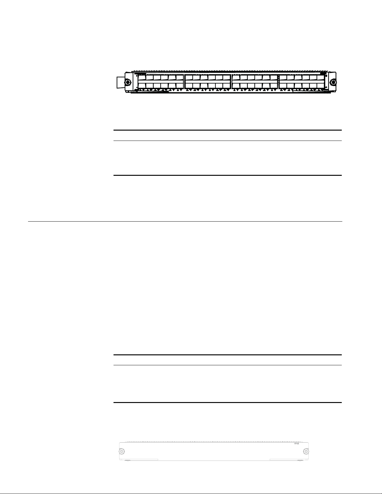
Panel and LEDs Figure 27 3C17538 module panel
The 3C17538 module has one LED for each 1000 Mbps optical port on its panel.
Ta bl e 57 Port LEDs on the 3C17538 module
LED Status Meaning
LINK/ACT Solid on A link is present.
Matching Cable You can select appropriate SFP optical modules for the 1000 Mbps SFP/LC optical
ports on the 3C17538 module accordingly to your needs. See
for the available SFP optical modules and their matching cable types.
Solid off No link is present.
Blinking The port is transmitting or
receiving data.
Ta bl e 64 on page 45
Application Modules Each Application Module is specially designed for high-speed processing of a
certain network service and shares some features with the I/O Modules.
Currently, the following application module are available to the Switch 8800
Family:
■ 3C17542: Network Monitoring Application Module
■ 3C17546: Firewall Application Module
■ 3C1754766: Network Monitoring Application Module
■ 3C17548: VPLS Application Module
3C17542 Network
Monitoring Application
Module
Technical specifications
The 3C17542 Network Monitoring Application Module provides no I/O ports.
Ta bl e 58 Technical specifications for the 3C17542
Item Specifications
CPU MPC755
Boot ROM 512 KB
SDRAM 256 MB
Physical dimensions (W x D) 366.7 x 340 mm (14.4 x 13.4 in.)
Front panel
Figure 28 Front panel of the 3C17542
Page 43
Application Modules 43
3C17546 Firewall
Application Module
Technical specifications
The 3C17546 Firewall Application Module provides eight Gigabit SFP/LC optical
ports.
Ta bl e 59 Technical specifications for the 3C17546
Item Specifications
CPU BCM1250
Boot ROM 512 KB
SDRAM 1 Gbps
Physical dimensions (W x D) 366.7 x 340 mm (14.4 x 13.4 in.)
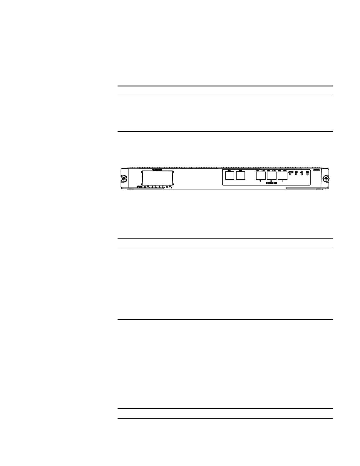
Front panel
Figure 29 Front panel of the 3C17546
The 3C17546 provides eight 1000Base-X ports, one Console port, one AUX port,
three 10/100Base-TX ports and four status LEDs (ATTACK, ACT, ALM and RUN)
from left to right on the front panel.
3CR1754766 IPsec
Module
Ta bl e 60 Status LEDs on the 3C17546
LED Color Status Meaning
ATTACK Red OFF The module is not attacked.
ON The module is attacked.
ACT Green OFF The module is in standby mode.
Blinking The module is in active mode.
ALM Red OFF There is no link alarm.
ON There is a link alarm.
RUN Green OFF The module is faulty.
Blinking The module operates normally.
Available cables
Ta bl e 64 on page 45 lists the available SFP modules and cable types for the
1000BASE-X SFP ports.
Technical specifications
The 3CR1754766 IPsec Module provides eight Gigabit SFP optical ports.
Ta bl e 61 Technical specifications for the 3CR1754766
Item Specifications
CPU BCM1250
Boot ROM 512 KB
Page 44
44 CHAPTER 2: I/O AND APPLICATION MODULES
Table 61 Technical specifications for the 3CR1754766
Item Specifications
SDRAM 512 MB
Physical dimensions (W x D) 366.7 x 340 mm (14.4 x 13.4 in.)
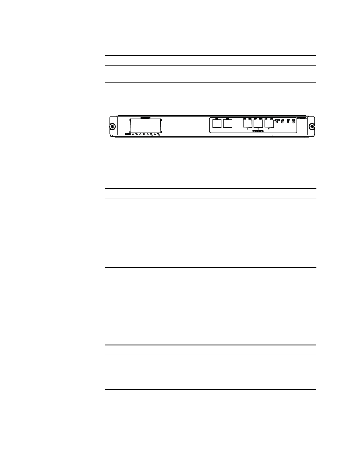
Front panel
Figure 30 Front panel of the 3CR1754766
The 3CR1754766 provides eight 1000Base-X ports, one Console port, one AUX
port, three 10/100Base-TX ports and four status LEDs (ATTACK, ACT, ALM and
RUN) from left to right on the front panel.
Ta bl e 62 Status LEDs on the 3CR1754766
3C17548 VPLS
Application Module
LED Color Status Meaning
ATTACK Red OFF The module is not attacked.
ON The module is attacked.
ACT Green OFF The module is in standby mode.
Blinking The module is in active mode.
ALM Red OFF There is no link alarm.
ON There is a link alarm.
RUN Green OFF The module is faulty.
Blinking The module operates normally.
Available cables
Ta bl e 64 on page 45 lists the available SFP modules and cable types for the
1000BASE-X SFP ports.
Technical specifications
The 3C17548 Virtual Private LAN Service (VPLS) Application Module provides no
I/O ports.
Ta bl e 63 Technical specifications for the 3C17548
Item Specifications
CPU MPC755
Boot ROM 512 KB
SDRAM 512 MB
Physical dimensions (W x D) 366.7 x 340 mm (14.4 x 13.4 in.)
Page 45

Front panel
Figure 31 Front panel of the 3C17548
Transceivers Ta bl e 64 documents the 3Com Switch 8800 Family transceivers.
Ta bl e 64 Transceiver Specifications
Optical Power Range (dBm)
3Com Transceiver
Name
XENPAKs
3Com 10GBASE-LR
XENPAK
3Com 10GBASE-SR
XENPAK
3Com 10GBASE-ER
XENPAK
Ordering
Number
3CXENPAK92 SMF 9 – 2 m – 10 km
3CXENPAK94 MMF 50 2,000 2 m - 300 m
3CXENPAK96 SMF 9 – 2 m – 40 km
Cable
Type
Core Size
(microns)
Model
Bandwidth
(MHz - Km)
Transmission
Range
(6.6 ft – 6 mi)
(3.2 ft - 990 ft)
(6.6 ft – 25 mi)
Wavelength
(nm)
1,300 -8.2 to 0.5 -14.4 to
850 -7.3 to
1,550 -4.7 to 4 -15.8 to -1 SC
Output Input Connector
-1.3
Transceivers 45
0.5
-11.1 to
-1.0
SC
LC
XFPs
3Com 10GBASE-LR XFP 3CXFP92 SMF 9 – 2 m – 10 km
3Com 10GBASE-SR XFP 3CXFP94 MMF 62.5 160 0.5 – 26 m
MMF 62.5 200 0.5 – 33 m
MMF 50 400 0.5 – 66 m
MMF 50 500 0.5 – 100 m
MMF 50 2,000 0.5 – 300 m
3Com 10GBASE-ER XFP 3CXFP96 SMF 9 – 2 m – 40 km
(6.6 ft – 6 mi)
(1.7 – 85 ft)
(1.7 – 108 ft)
(1.7 – 217 ft)
(1.7 – 328 ft)
(1.7 – 984 ft)
(6.6 ft – 25 mi)
1,300 -8.2 to 0.5 -14.4 to
850
1,550 -4.7 to 4 -15.8 to -1 LC
-4.0 to
-1.1
0.5
-9.9 to -1.0 LC
LC
1000 Mbps SFPs
3Com 1000BASE-SX
SFP
3Com 1000BASE-LX
SFP
3Com 1000BASE-LH70
SFP
3Com 1000BASE-T SFP 3CSFP93 CAT5 – – 100 m (328 ft) – – – RJ-45
3CSFP91 MMF 62.5 160 2 – 220 m
MMF 62.5 200 2 – 275 m
MMF 50 400 2 – 500 m
MMF 50 500 2 – 550 m
3CSFP92 MMF 62.5 500 2 – 550 m
MMF 50 400 2 – 550 m
MMF 50 500 2 – 550 m
SMF 9 – 2 m – 10 km
3CSFP97 SMF 9 – 2 m – 70 km
(6.6 – 721 ft)
(6.6 – 902 ft)
(6.6 – 1,640 ft)
(6.6 – 1,804 ft)
(6.6 – 1,804 ft)
(6.6 – 1,804 ft)
(6.6 – 1,804 ft)
(6.6 ft – 6 mi)
(6.6 ft – 43 mi) ft
850 -9.5 to 0 -17 to 0 LC
1,300 -9.5 to -3 -20 to -3 LC
1,550 0 to 3 -24 to -3 LC
Page 46

46 CHAPTER 2: I/O AND APPLICATION MODULES
Switch 8800 Port Densities
Ta bl e 65 describes the modules that are available for the Switch 8800, their
maximum port densities, and whether or not the module supports MPLS or IPv6.
Ta bl e 65 Switch 8800 Available Modules
SKU Description
3C17511 1-port 10GBASE-X (XENPAK) 12 No No 1
3C17512 2-port 10GBASE-X (XFP) 24 No No 2
3C17513 12-port 1000BASE-X (SFP) 144 No No 1
3C17514 24-port 1000BASE-X (SFP) 288 No No 2
3C17516 24-port 10/100/1000BASE-T (RJ-45) 288 No No 2
3C17525 1-port 10GBASE-X (XENPAK) Advanced 12 Yes No 1
3C17526 4-port 10GBASE-X (XFP) 48 No No 2
3C17527 2-port 10GBASE-X (XFP) Advanced 24 Yes No 2
3C17528 48-port 10/100/1000 BASE-T (RJ-45) 576 No Yes** 1
3C17530 24-port 1000BASE-X (SFP) Advanced 288 Yes No 2
3C17531 24-port 10/100/1000BASE-T (RJ45) Advanced 288 Yes No 2
3C17532 48-port 10/100/1000BASE-T (RJ45) Access 576 No Yes** 1
3C17533 24-port 1000BASE-X (SFP) IPv6 Module 288 No Yes** 2
3C17534 24-port 10/100/1000BASE-T (RJ-45) IPv6 Module 288 No Yes** 2
3C17536 4-port 10GBASE-X (XFP) QUAD IPv6 48 No Yes** 4
3C17538 48-port 1000BASE-X (SFP) IPv6 576 No Yes** 1
3C17542 Network Monitoring Module No No 1
3C17546 Firewall Module 8 No No*** 1
3CR1754766 IPsec Module 8 No No*** 1
3C17548 Virtual Private LAN Service (VPLS) No No 1
Max Port
Density*
MPLS IPv6
Fabric
Adapters
*Maximum port densities stated for largest chassis model, the Switch 8814 (14
slots)
**IPv6 capable hardware module; future system software upgrade required for
IPv6 routing.
*** The FW Module and IPsec Module will not support IPv6 in first IPv6 release
Page 47

3
INSTALLATION PREPARATION
Safety Recommendations
General Safety
Recommendations
Safety
Recommendations
against Electricity
To avoid possible bodily injury and device impairment, please read the following
safety recommendations carefully before installing the Switch 8800 Family. The
recommendations do not cover every possible hazardous condition.
■ The Switch 8800 Family use redundant PSUs. Turn off all PSUs and remove all
the power cords before opening the chassis.
■ Keep the chassis clean and dust-free.
■ Keep the chassis and installation tools away from walk areas.
■ Look carefully for possible hazards in your work area, such as ungrounded
power extension cables, missing safety grounds, and moist floors.
■ Locate the emergency power-off switch in the room before installation. Shut
the power off at once in case accident occurs.
■ Unplug all the power cords and external cables before moving the chassis.
■ Do not maintain the equipment alone when it has been powered.
■ Never assume but check each time that power has been disconnected from a
circuit.
■ Do not place the switch on a moist area and avoid liquid flowing into the
switch.
Safety
Recommendations in
Moving the Switch 8800
Family
c
The Switch 8800 Family are rather big and heavy, so follow the recommendations
below when moving it.
■ Remove all the external cables (including power cords) before moving the
chassis.
■ Do not move the switch alone. Work with another person.
■ Move the switch slowly and stably. Never move suddenly or twist your body.
■ Move the switch at stable and consistent paces with your peer. Keep balance of
your body.
CAUTION: You can only hold the handles at both sides of the chassis when
moving the switch, but not the plastic panel of the chassis, the handle of the fan
frame, the handle of the PSUs or the air vents of chassis.
As these parts are not designed for bearing the weight of the entire chassis, any
attempt trying to carry the switch with these parts may impair the switch and even
injure yourself.
Page 48

48 CHAPTER 3: INSTALLATION PREPARATION
Wearing an
ESD-Preventive Wrist
Strap
c
To prevent the electronic components from being damaged by the electrostatic
discharge (ESD), take ESD measures for the area where the switch is located and
note the issues below:
■ Always wear an ESD-preventive wrist strap when installing the parts, especially
the electric printed circuit boards.
■ Hold the circuit board by the edge. Do not touch the components or the
electric printed circuit.
Take the following steps to use the ESD-preventive wrist strap.
Step 1: Wear the wrist strap on your wrist.
Step 2: Lock the wrist strap tight around your wrist to keep good contact with the
skin.
Step 3: Insert it into the hole peculiar to ESD-preventive wrist strap in the chassis
or attach it to the grounding screw of the chassis the alligator clips.
Step 4: Make sure that the ESD-preventive wrist strap is well grounded.
CAUTION: For the sake of safety, check the resistance of the ESD-preventive wrist
strap. The resistance reading should be in the range of 1 to 10 Mohm between
human body and the ground.
Safety
Recommendations
against Laser
c
Examining Installation Site
Temperature/Humidity
Requirements
Some I/O modules of the Switch 8800 Family have optical interfaces. In operating
status, it is dangerous to stare into the open optical interface because the laser
being transmitted through the optical fiber produces a small beam of light which
has very high power density and is invisible to human eyes; when a beam of light
enters the eye, retina may be burned.
CAUTION: The laser inside the optical fiber may hurt your eyes.
The Switch 8800 Family can only be used indoors. To ensure that the switch works
normally and to prolong its service lifetime, the following requirements should be
met in terms of installation environment.
To ensure the normal operation and service lifetime of a switch, proper
temperature and humidity should be maintained in the equipment room.
Long-lasting high humidity in the equipment room is prone to poor insulation or
even leakage of the insulating material. Sometimes, the mechanical performance
deterioration, the rustiness and corrosion of some metal parts are also more likely
to occur. If the relative humidity is too low, the captive screws may become loose
due to the insulation washer contraction. Meanwhile, the electrostatic is likely to
be produced in the dry environment, which will jeopardize the CMOS circuit of the
switch. The higher the temperature, the greater the damage it will do to the
switch. Long-lasting high temperature will speed up the aging process of the
insulating materials, greatly lower the reliability of the switch, and therefore affect
its service life seriously.
Page 49

Examining Installation Site 49
Cleanness Requirements Dust is a hazard to the operating safety of the switch. The indoor dust
accumulated on the chassis can cause electrostatic absorption, which may result in
the poor contact of the connector or metal contact point. This happens more
frequently when indoor relative humidity is low, which will not only shorten the
service life of the switch, but also cause communication failure.
The required specifications on dust content and particle diameter in an equipment
room are shown in the following table.
Ta bl e 66 Limitation on dust content in equipment room
Mechanical active material Unit Content
Dust particle particles/m
Note: Dust particle diameter ‚≥ 5µm
3
‚≤3 x 10
(No visible dust on desk in three days)
4
Besides the dust specifications, the equipment room of the switch should also
meet the rigorous requirements for the content of salt, acid and sulfide in the air.
These harmful gases could accelerate the metal erosion and the aging process of
some parts. Incursion of harmful gases, such as SO
, H2S, NO2, NH3, and Cl2,
2
should be prevented. The specific limitation values of these harmful gases are
given in the following table.
Anti-Static
Requirements
Ta bl e 67 Harmful gas limits in an equipment room
Gas Average (mg/m3) Max. (mg/m3)
SO2 0.3 1.0
H2S 0.1 0.5
NO2 0.004 0.15
NH3 1.0 3
Cl2 0.1 0.3
Any possible interference sources, no matter outside or inside the system, affect
the switch in use in a way of capacitive coupling, inductive coupling,
electromagnetic radiation, common impedance (including the grounding system)
coupling or conducting line (power line, signaling line and transmission line etc.).
To prevent the interference, you should:
■ Take effective measures against electrical net interference for power supply
system.
■ Separate the working ground of the switch from the grounding device of the
power supply equipment or lightning-protection grounding device as far as
possible.
■ Keep the switch far away from the radio launcher, radar launcher, and
high-frequency devices working in the high current.
Grounding
Requirements
■ Adopt electromagnetic shielding if necessary.
A good grounding system is not only the basis essential to the stable and reliable
switch operation, but also an important guarantee of lightning protection,
anti-interference and ESD-prevention. The user must provide good grounding
system for the switch.
Page 50

50 CHAPTER 3: INSTALLATION PREPARATION
Power Supply
Requirements
The Switch 8800 Family adopts redundant PSUs for AC PSU:
Rated voltage: 100 VAC to 240 VAC, 50 Hz or 60 Hz
Maximum tolerance: 90 VAC to 264 VAC, 50 Hz or 60 Hz
Maximum power output: 1200 W (Switch 8807)/2000 W (Switch 8810/Switch
8814)
Space Requirements For the sake of adequate ventilation and easy equipment maintenance, you are
recommended to keep one meter of clearance between the rear/front of the
switch cabinet and the wall surface or other devices. If the optional cabinet is
desired, the clear height of the equipment room must be more than 3 meters
inclusive.
Cabinet-Mounting
Requirements
Before cabinet-mounting the switch, make sure that the cabinet meets the
following requirements:
■ Better mount the switch in an open cabinet. However, if you want to mount it
in a closed cabinet, make sure of the availability of a good ventilation system.
■ Make sure that the cabinet stands steadily enough to support the weight of the
switch and the accessories.
■ Make sure that the switch fits the cabinet size. Leave some clearance beside
the left and right panels of the switch for chassis ventilation.
Installation Tools
n
Ta bl e 68 Required installation tools
Long tape, ruler (1 meter in length), marking pen, powder
marker, pencil
One percussion drill, several drill bits, one vacuum cleaner
Flat-module screwdriver P4 -- 75 mm
Phillips screwdriver P1 -- 100mm, P2 -- 150mm and P3 -250mm
Socket wrench M5
Box-end wrench M6
Double ring spanner (10-12) or open-end wrench (10-12)
Sharp-nose pliers, diagonal pliers, vices, hand-held electric
drill, file, handsaw, crowbar, rubber hammer
Brush, tweezers, paper knife, hand bellows, electric iron,
solder wire, fork, ladder
ESD-preventive wrist strap, cable stripper, crimping pliers,
RJ-45 crimping pliers, wire punchdown tool
Multimeter, 500V Meg-ohmmeter (used for measuring the
insulation resistance), error detector, optical power meter,
earth resistance tester
General
tools
Special tools
Meters
Measure and
lineation tools
Drills
Fastening tools
Small tools
Auxiliary tools
The instruments and tools are not shipped with the Switch 8800 Family and it is
up to the users to ensure their availability.
Page 51
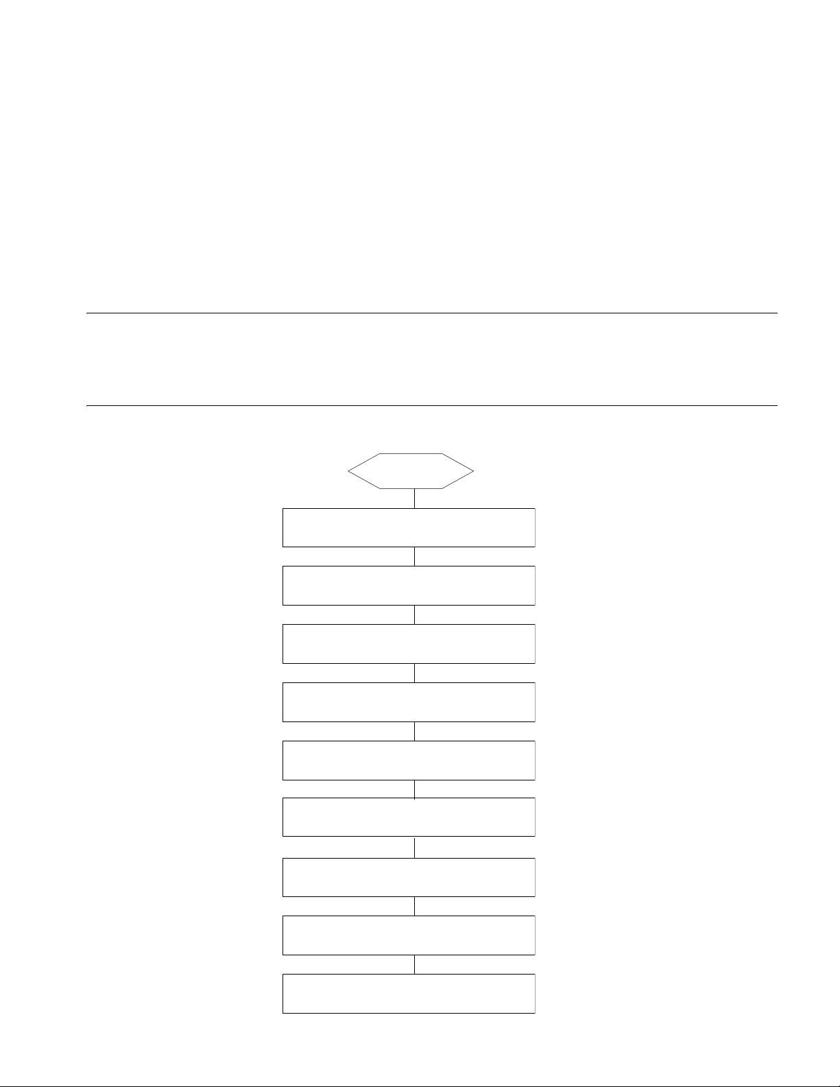
4
SWITCH INSTALLATION
The Switch 8800 Family shall be installed indoors in a fixed place.
Confirming Installation Preparation
Installation Flow Figure 32 Installation Flow
■ Make sure that you have read Chapter 3 Installation Preparation carefully.
■ All requirements mentioned in Chapter 3 Installation Preparation have been
met.
Start
Confirm preparations
Check installation site
Install cabinet
Install chassis and
other components
Connect PGND wire/power cord
Power distribution box in cabinet
Cabling rack and fan tray
Insert I/O modules or
Application modules
Connect cables to I/O modules
or Application modules
Page 52

52 CHAPTER 4: SWITCH INSTALLATION
Mounting the Switch in User-Supplied Cabinet
Cabinet Configuration
Guideline
c
CAUTION:
■ Even if no PoE external power supply is installed, it is recommended that you
reserve the PoE power supply slot (just cover a 4 U blank filler panel) in the
cabinet for later PoE expansion.
■ For components of 4 U or higher, such as chassis and PoE power supply, more
screws are required to secure the slide rails in the cabinet considering their
weight.
■ You can adjust the specific height of every slot as needed. The following
guideline is just for reference.
One Switch 8807 chassis in a cabinet
The components and their height are as follows (from bottom up):
■ Blank filler panel (2U)
■ Cabling frame (2U)
■ External PoE power supply (or blank filler panel if no external PoE power supply
is installed) (4U)
■ Blank filler panel (1U)
■ Back cabling frame (1U)
■ New Switch 8807 chassis (11U)
■ Blank filler panel (1U)
■ Cabling frame (2U)
Page 53

Mounting the Switch in User-Supplied Cabinet 53
Figure 33 One Switch 8807 chassis in a cabinet
Switch 8807 11U
(1) Blank filler panel (2) Cabling frame
(3) Backward cabling frame (4) Reserved for external PoE power supply
Guideline: The space marked in Figure 33 must be reserved, and the remaining is
at your disposal.
Two Switch 8807 chassis in a cabinet
The components and their height are as follows (from bottom up):
■ Blank filler panel (2U)
■ Cabling frame (2U)
■ External PoE power supply (or blank filler panel if no external PoE power supply
is installed) (4U)
■ Blank filler panel (1U)
■ Back cabling frame (1U)
■ Switch 8807 chassis (11U)
■ Blank filler panel (1U)
■ Cabling frame (2U)
■ Switch 8807 chassis (11U)
Page 54
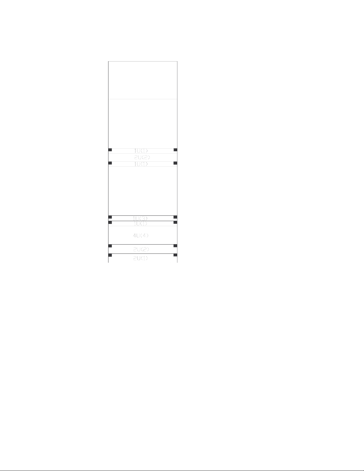
54 CHAPTER 4: SWITCH INSTALLATION
Figure 34 Two Switch 8807 chassis in a cabinet
Switch 8807 11U
Switch 8807 11U
(1) Blank filler panel (2) Cabling frame
(3) Backward cabling frame (4) Reserved for external PoE power supply
Guideline: The space marked in Figure 34 must be reserved, and the remaining is
at your disposal.
One Switch 8810 chassis in a cabinet
The components and their height are as follows (from bottom up):
■ Blank filler panel (2U)
■ Cabling frame (2U)
■ External PoE power supply (or blank filler panel if no external PoE power supply
is installed) (4U)
■ Blank filler panel (1U)
■ Back cabling frame (1U)
■ Switch 8810 chassis (14U)
■ Blank filler panel (1U)
■ Cabling frame (2U)
Page 55

Mounting the Switch in User-Supplied Cabinet 55
Figure 35 One Switch 8810 chassis in a cabinet
Switch 8810 14U
(1) Blank filler panel (2) Cabling frame
(3) Backward cabling frame (4) Reserved for external PoE power supply
Guideline: The space marked in Figure 35 must be reserved, and the remaining is
at your disposal.
One Switch 8814 chassis in a cabinet
The components and their height are as follows (from top down):
■ Blank filler panel (2U)
■ Cabling frame (2U)
■ External PoE power supply (or blank filler panel if no external PoE power supply
is installed) (4U)
■ Blank filler panel (1U)
■ Back cabling frame (1U)
■ Switch 8814 chassis (17U)
■ Blank filler panel (1U)
■ Cabling frame (2U)
Page 56

56 CHAPTER 4: SWITCH INSTALLATION
Figure 36 One Switch 8814 chassis in a cabinet
Switch 8814 17U
Mounting the Switch in
the Cabinet
(1) Blank filler panel (2) Cabling frame
(3) Backward cabling frame (4) Reserved for external PoE power supply
Guideline: The space marked in Figure 36 must be reserved, and the remaining is
at your disposal.
Take the following steps to install the Switch 8800 Family in a 19-inch cabinet.
Step 1: Confirm before installation
■ Make sure that the cabinet has been well fixed. The layout inside the cabinet
for switch installation has been well done and there is no obstruction inside or
around the cabinet.
■ Make sure that the switch is ready for installation and has been carried to a
place convenient for further moving near the cabinet.
Step 2: Mount a shelf inside the cabinet depending on the position where you
want to put the switch.
Step 3: Install the cabling rack and attach the mounting ears shipped with the
switch onto the switch.
Step 4: Carry the switch at both sides with another person to the place in front of
the cabinet slowly.
Step 5: Lift the switch a little higher than the cabinet shelf, put it on the shelf, and
push it into the cabinet.
Page 57

Connecting PGND Wire and Power Cord
Connecting PGND Wire
Connecting PGND Wire and Power Cord 57
Step 6: Align the mounting ears with the square holes in the posts of the cabinet,
and fasten the screws in the holes to fix the switch in the cabinet.
c
n
n
CAUTION: For the safety of operators and equipment, the switch must be well
grounded. The resistance reading between switch chassis and the ground must be
less than 1 ohm.
Common grounding environment
Step 1: Remove the screw from the grounding hole in the switch chassis.
Step 2: Wear the connector of the PGND wire accompanied with the switch on
the grounding screw.
Step 3: Insert the grounding screw into the grounding hole and screw it down.
Step 4: Connect the other end of the ground wire to the ground bar of the switch.
Generally, the cabinets installed in equipment rooms are equipped with ground
bar. In this case, you can connect the PGND wire of the switch to the ground bar
for it.
Other grounding environment
Following are some methods for grounding the switch in different grounding
environments that you are likely to encounter when installing the switch at
different places.
Rather than specifying the switch model or showing the actual location of the
switch power input or grounding screw, the following figures are primarily
intended for illustrating the switch grounding, either via grounding screw or
power input, in specific grounding environments.
■ If a ground bar is available, attach one end of the yellow-green PGND wire of
the switch to a grounding bolt of the ground bar and fasten the captive nuts.
Note that the fire main and lightning rod of a building are not suitable for
grounding the switch. The PGND wire of the switch should be connected to
the grounding device in the equipment room. (For the Switch 8800 Family, the
grounding screw is on the rear panel. Connect it as illustrated in
Figure 37).
Page 58
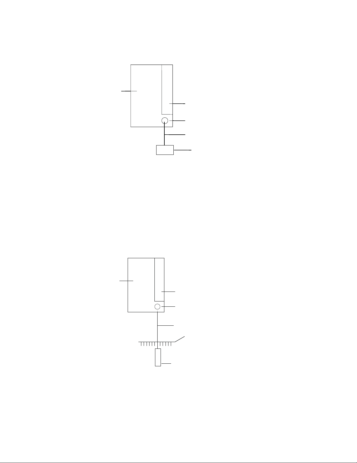
58 CHAPTER 4: SWITCH INSTALLATION
˄5˅
˄1˅
˄2˅
˄3˅
˄4˅
˄5˅
˄1˅
˄2˅
˄3˅
˄4˅
˄5˅
˄1˅
˄2˅
˄3˅
˄4˅
˄5˅
˄1˅
˄2˅
˄3˅
˄4˅
˄5˅
˄1˅
˄2˅
˄3˅
˄4˅
˄5˅
˄1˅
˄2˅
˄3˅
˄4˅
˄6˅
˄1˅
˄2˅
˄3˅
˄5˅
˄4˅
˄6˅
˄1˅
˄2˅
˄3˅
˄5˅
˄4˅
˄6˅
˄1˅
˄2˅
˄3˅
˄5˅
˄4˅
Figure 37 Ground the switch when ground bar is available
(1) Air filter (2) Grounding screw
(3) PGND wire (4) Ground bar of the equipment room
(5) Rear panel of the switch
■ If there is no ground bar but earth nearby and the grounding body is allowed
to be buried, you can simply hammer an angle iron or steel pipe no shorter
than 0.5 m into the earth. In this case, the yellow-green PGND wire should be
welded with the angle iron (steel pipe) and the joint should be processed
against eroding. (For the Switch 8800 Family, the grounding screw is on the
rear panel. Connect it as illustrated in
Figure 37).
Figure 38 Ground the switch when allowed to bury grounding body nearby
(1) Air filter (2) Grounding screw
(3) PGND wire (4) Ground bar of the equipment room
(5) Angle steel (6) Rear panel of the switch
■ If both ground bar and the conditions for burying the grounding body are not
available, an AC-powered Ethernet switch can be grounded using the PE wire
of the AC power supply. In this case, make sure that the PE wire of the AC
Page 59
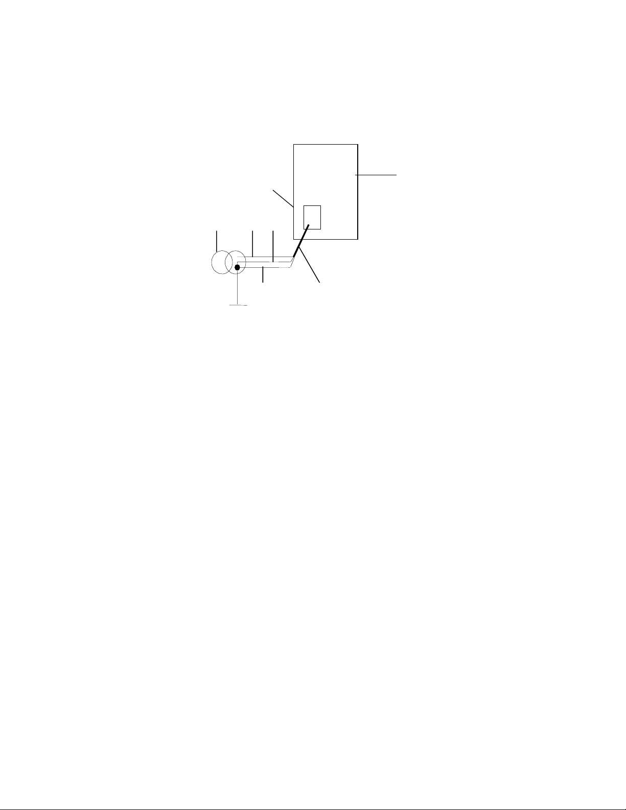
Connecting PGND Wire and Power Cord 59
(1) (2)(5)
(3) (4)
(6)
(7)
(1) (2)(5)
(3) (4)
(6)
(7)
power supply has been well grounded at the power distribution room or AC
power supply transformer side.
Figure 39 Ground the switch via AC PE wire
(1) Live line (2) Neutral line
(3) PE line (4) 3-core AC input cable
(5) Transformer (6) AC power input
(7) Front panel of the switch
Connecting AC Power
Cord
c
CAUTION:
■ For lightning protection, the AC power should be led through an external
lightning device into the switch.
■ Make sure the power switch on the PSU is at OFF position before connecting
the power cord.
On the front panel of AC PSU, there is a plug-retention clamp.
Take the following steps to connect the AC power cord (coming with the switch)
to the Switch 8807/Switch 8810/Switch 8814:
Step 1: Turn the clamp at the left of the PSU front panel to the right.
Step 2: Insert the plug at one end of the AC power cord into the socket on the
PSU.
Step 3: Turn the clamp to the left until it grips the plug.
Step 4: Insert the other end of the power cord into an external power socket.
Page 60
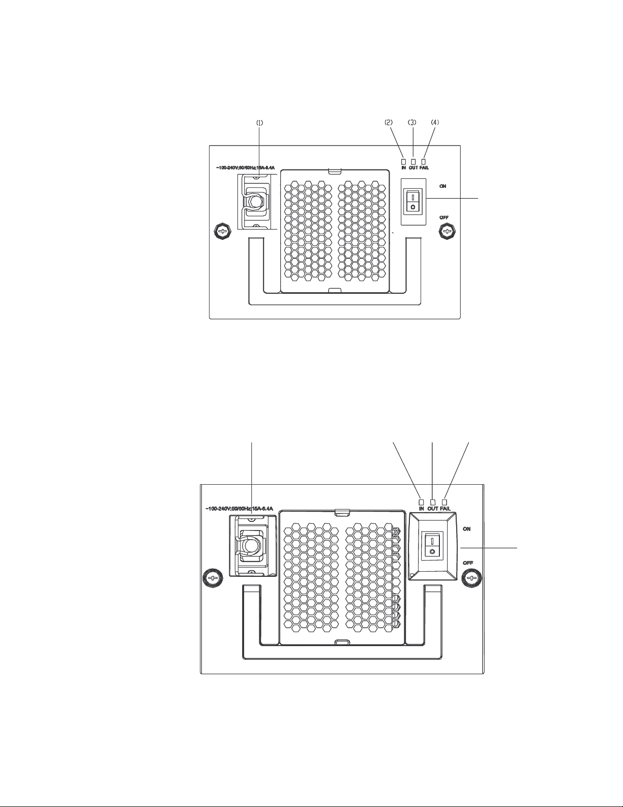
60 CHAPTER 4: SWITCH INSTALLATION
Figure 40 Connect AC power cord to the Switch 8807
(5)
(1) Connector-retention clamp (2) Input LED
(3) Output LED (4) Fail LED
(5) Power switch
Figure 41 Connect AC power cord to the Switch 8810/Switch 8814
(1)
(2)
(3)
(4)
(5)
(1) Connector-retention clamp (2) Input LED
(3) Output LED (4) Fail LED
(5) Power switch
Page 61
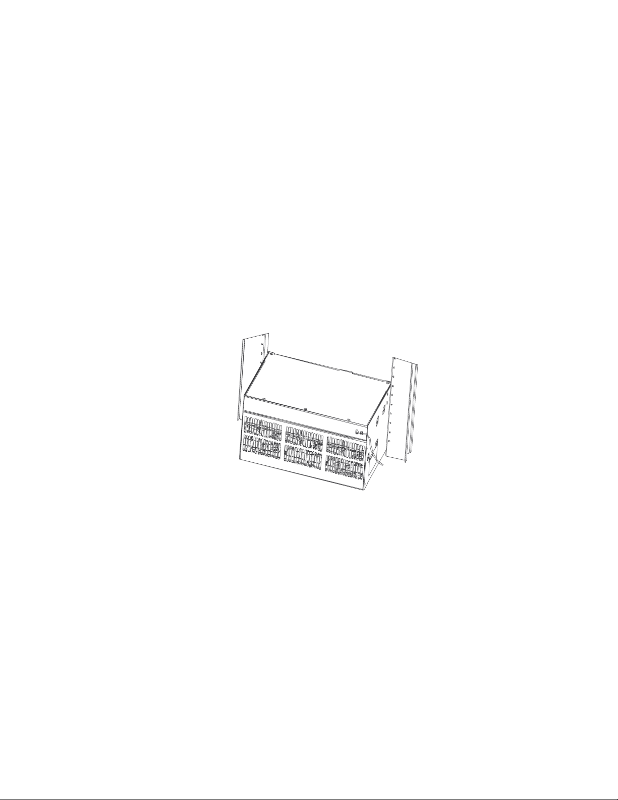
Connecting PGND Wire and Power Cord 61
Connecting PoE Power
Cord
n
The Switch 8807/Switch 8810/Switch 8814 uses PSE4500-A external PoE power
supply, which is connected to the switch through the PoE module at the front
bottom of the switch to provide power to PDs (powered devices) under the switch.
This section only focuses on the cable connection between the external PoE
power supply and the Switch 8800 Family switch. For the installation of the
external PoE power supply, see the manual shipped with the power supply.
Grounding PoE chassis
You must ground the PoE chassis before connecting the PoE power cord to it.
Follow these steps:
Connect the 6 AWG cable of the wiring terminal (with M6 hole) to the grounding
screw on the rear panel of the switch, as shown in
Connect the other end of the cable to the grounding bar or other grounding
terminals.
Figure 42 Ground PoE chassis
Figure 42.
c
(1) Chassis grounding screw
Connecting PoE power cable
Loosen the mounting screw of the PoE entry module with a cross screwdriver.
Insert the -48V OT terminal (blue) of the DC power cord to the NEG (-) terminal of
the PoE entry module and fasten the mounting screw; insert the other end to the
NEG (-) terminal of the external PoE power supply.
Insert the GND OT terminal (black) of the DC power cord to the RTN (+) terminal
of the PoE entry module and fasten the mounting screw; insert the other end to
the NEG (-) terminal of the external power supply.
CAUTION:
■ Observe the signs on devices and connect the cables correctly.
■ Choose right cables based on the load.
Page 62
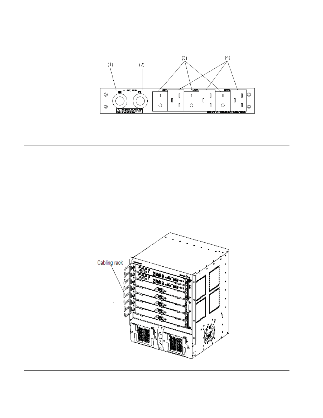
62 CHAPTER 4: SWITCH INSTALLATION
Figure 43 Front panel of external PoE Power Rack (3C17509)
(1) DC output terminal: NEG(-) (2) DC output terminal: RTN(+)
(3) AC input switch (4) AC input socket
Installing Cabling Rack For your convenience, cabling racks are shipped with the Switch 8800 Family. Take
the following steps to install the rack.
Step 1: Face the I/O module slots of the switch;
Step 2: Attach the left mounting ear (the one with an elliptical hole on one surface
and a recessed hole on the other) onto the cabling rack and fix it with screws (one
cabling rack for Switch 8807/Switch 8810 and two for Switch 8814);
Step 3: Install mounting ears onto the both sides of the switch.
Figure 44 The position of the cabling rack
Installing Fan Tray The fan tray is hot swappable.
Page 63
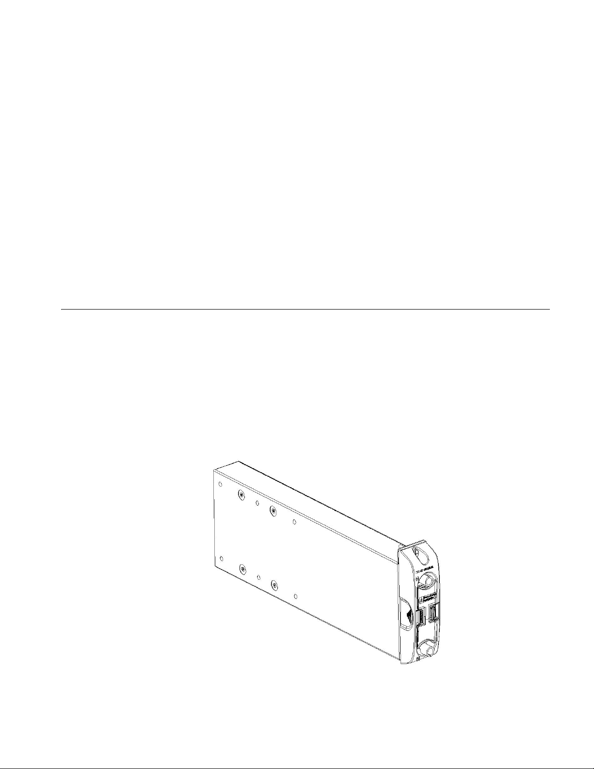
Installing PoE Lightning Protection Box 63
c
n
Installing PoE Lightning Protection Box
CAUTION: In case of bodily injuries, do not touch any naked wire, terminal or
other parts of the product with hazardous voltage labels.
Step 1: Wear the ESD-preventive wrist strap, making sure that it makes good skin
contact; take the fan tray out from the packing bag.
Step 2: Hold the fan tray in right direction (just check the direction of instructional
words, and if you insert it upside down, the plug of the fan tray cannot touch the
right socket inside the chassis), with one hand on its handle and the other hand at
its bottom the ejector levers on the fan tray with both hands and pull them
outward. Align the fan tray with the guides in the chassis and slide it gently into
the slot until its plug touches the chassis socket.
Step 3: Fasten the mounting screws on the panel of the fan tray with a screw
driver.
The above installation steps are just for replacing your fan tray, since the fan tray
is delivered together with the chassis and no initial installation is required.
The 3C17510 PoE Entry Module is hot-swappable.
c
CAUTION: Do not touch any exposed wires, terminals, and device parts marked as
hazard to avoid hurting your body.
1 Wear an ESD-preventive wrist strap and ensure it is well grounded. Unpack the
PoE lightning protection box, which is shown in
Figure 45 PoE Entry Module
Figure 45.
2 Keep the PoE Entry Module in the right direction, that is, correct letter direction
(do not turn it upside down, or you will not be able to fully insert it into the chassis
due to the limitation on the back structure of the box, nor can you fasten the
chassis fixing screw), hold it with one hand at the bottom and with another hand
Page 64
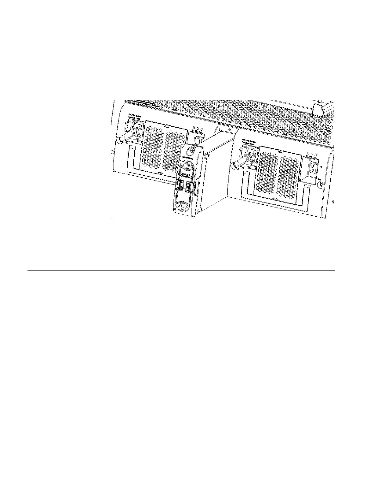
64 CHAPTER 4: SWITCH INSTALLATION
at the front panel, and then slide it smoothly along the guide rail to the slot, until
it fits into the chassis, with its plug fully touching the socket inside the chassis. See
Figure 46.
Figure 46 Install PoE lightning protection box
3 Fasten the screw on top of the PoE lightning protection box.
n
Installing I/O modules The I/O modules of the Switch 8800 Family are hot-swappable.
Generally, the PoE lightning protection box is shipped with the chassis of the
switch you ordered. So you need not to install the box. The above installation
procedure is needed only when you are changing the fan frame.
Step 1: Wear the ESD-preventive wrist strap, making sure that you have grounded
it well. Take the I/O module out of the packing bag.
Step 2: Unscrew the mounting screws holding the blank filler panel in the slot
where you plan to install the I/O module, and remove the panel from the slot.
Step 3: Hold the ejector levers on the fan tray with both hands and pull them
outward. Align the I/O module with the guides in the chassis and slide it gently
into the slot until the positioning pin of the I/O module touches the hole in the
chassis.
Step 4: Pull the ejector levers inward, locking the positioning pin into the hole.
Step 5: Fix the I/O module by fastening the mounting screws on the I/O module
with a screw driver.
n
Put the removed blank filler panel away for future use.
For the Switch 8800 Family, the Application Module can be installed in the I/O
module slot in the same way as installing the I/O module board.
Page 65
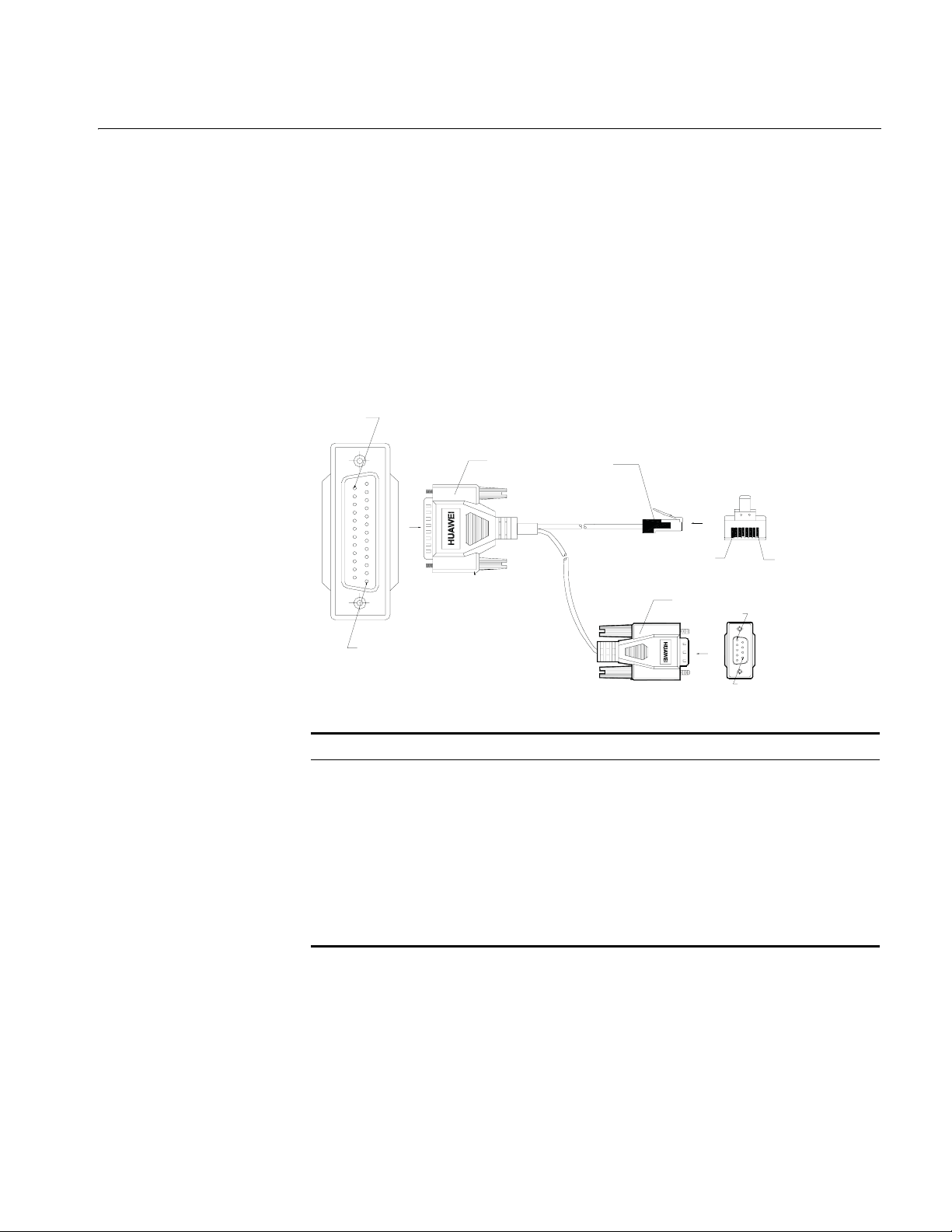
Connecting Interface
Enlarged A side
Pos. 25
A
DB 25 Female
8P8C Plug
Enlarged B side
Pos.1
Pos.8
DB9 Female
Enlarged C side
Pos.1
Pos.9
C
Pos.1
B
Cables
Connecting Interface Cables 65
Connecting Console
Cable
Introduction
Console cable is an 8-core shielded cable. At one end of the cable is a crimped
RJ-45 connector that is to be plugged into the console port of the switch. At the
other end of the cable are a DB-9 (female) connector and a DB-25 (female)
connector. You can plug either of them into the 25-pin (male) or 9-pin (male) serial
port on the console terminal as needed. The following figure illustrates the
console cable.
Figure 47 Console cable
Ta bl e 69 Console cable pinouts
RJ-45 Signal Direction DB-25 DB-9
1 RTS ← 4 7
2 DTR ← 20 4
3 TXD ← 2 3
4 CD → 8 1
5 GND − 7 5
6 RXD → 3 2
7 DSR → 6 6
8 CTS → 5 8
Connecting console cable
Take the following steps to connect the console cable, when configuring the
switch on the terminal.
Step 1: Plug the DB-9 or DB-25 female connector of the console cable into the
serial port of the PC/terminal where the switch is to be configured.
Step 2: Connect the RJ-45 connector of the console cable to the console port of
the switch.
Page 66
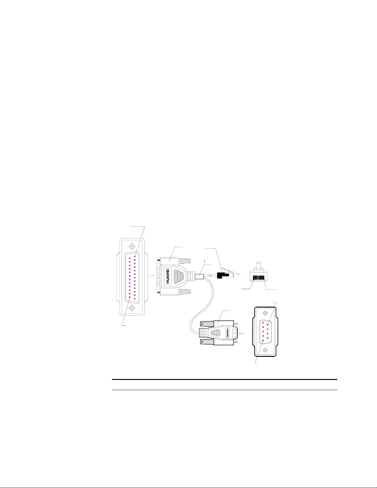
66 CHAPTER 4: SWITCH INSTALLATION
Enlarged A side
Pos.1
Pos.25
DB25 Male
A
DB9 Male
Label
8P8C PLUG
B
Enlarged B side
Pos.1 Pos.8
Enlarged C side
Pos.9
Pos.1
C
n
remove the console cable into or from the PC serial port.
When connecting the console cable, first connect the DB9/DB25 end to the PC
serial port and then the RJ45 end to the console port of the switch. And removing
the console cable is just in inverse order.
When removing the console cable, first remove the RJ-45 end and then the
DB9/DB25 end.
Connecting AUX Cable You need an AUX cable when configuring the Switch 8800 Family with the remote
modem dial-up approach.
Introduction
AUX cable is an 8-core shielded cable. At one end of the cable is an
RS-232-compliant RJ-45 connector that can be plugged into the console port of
the switch. At the other end are DB-9 (male) connector and DB-25 (male)
connector. You can plug either of them into the DB-9 (female) or DB-25 (female)
port of the modem as needed. The following figure illustrates the AUX cable.
Figure 48 AUX cable
The PC serial port is not hot-swappable, so you are not allowed to insert or
Ta bl e 70 AUX cable pinouts
RJ-45 Signal Direction DB-25 DB-9
1 RTS → 4 7
2 DTR → 20 4
3 TXD → 2 3
4 CD ← 8 1
5 GND - 7 5
6 RXD ← 3 2
7 DSR ← 6 6
Page 67

Connecting Interface Cables 67
PIN #8
PIN #1
Table 70 AUX cable pinouts
RJ-45 Signal Direction DB-25 DB-9
8 CTS ← 5 8
Connecting AUX cable
Step 1: Plug the RJ-45 connector of the AUX cable into the AUX port of the
switch.
Step 2: Plug the DB-25 (male) or DB-9 (male) connector at the other end into the
serial port of the analog modem.
Connecting Category-5
Shielded Cable
Connecting Fiber
n
Introduction to RJ-45 connector
Being RJ-45 connector, the 10Base-T/100Base-TX port of the Switch 8800 Family
supports MDI/MDIX auto-sensing and will be connected using the category-5
shielded cable. The following figure illustrates an RJ-45 connector.
Figure 49 RJ45 connector
Connecting category-5 shielded cable
Step 1: Plug one end of the network cable into the desired Ethernet RJ-45
connector on the switch.
Step 2: Plug the other end of the cable into the RJ-45 port of the peer device.
All the megabit and gigabit optical modules available for the Switch 8800 Family
are SFP modules that provide LC user ports.
Introduction to fiber connector
n
■ When selecting a fiber network facility, make sure that the type of the
connector and the fiber match the adopted optical port.
■ Before connecting the fiber, make sure that the receive-end optical power does
not exceed the upper threshold of the receiving optical power. Excessive
receiving optical power is very likely to burn the optical module.
Fiber connectors are indispensable passive components in an optical fiber
communication system. Their application allows the removable connection
between optical channels, which makes the optical system debugging and
maintenance more convenient and the transit dispatching of the system more
flexible. Among various fiber connectors, only LC connector will be introduced
here.
■ LC fiber connector
Page 68

68 CHAPTER 4: SWITCH INSTALLATION
Figure 50 LC connector
Connecting fiber
Step 1: Plug one end of the fiber into the SFP optical module of the Switch 8800
Family.
Step 2: Connect the other end of the fiber into the corresponding device.
c
Cable Routing Recommendations
Freestanding Switch on
Tabletop
Cabinet-Mounting
Switch
CAUTION: When the optical interface has not been connected with a fiber
connector or its dust-proof mesh is open, there might be some invisible radiation
emitted from the optical interface. So do not look into the optical interface
directly.
Cover the optical interface if there is no connector plugged in.
For only selling an integrated chassis, you do not have to care about the cabling
inside or outside the cabinet. All the I/O module cables are routed from the left
side of the chassis (along the cabling channel), and the chassis power cords
(AC/DC power cords) are routed in the front of the chassis.
If the switch is mounted in a 19-inch standard cabinet or B68-22 cabinet, the I/O
module cables are bound on the cabling rack at the left side of the chassis and are
routed up or down to pass through the chassis top or the raised floor depending
on the available equipment room condition (that is, the signal cables are routed
into the chassis either from the cabling rack on the chassis top or from the cabling
trough under the floor) of the exchange office. The power cords run along the
left-front of the chassis and out of the chassis either from the top or the raised
floor depending on the equipment room conditions (DC power distribution
cabinet, lightning protection box, and terminal block, etc.) of the exchange office.
Cable Management
Cable Management
Requirements
■ Bundle and put the cables inside the cabinet in a straight and neat way. No
intertwinement or bending is allowed.
Page 69
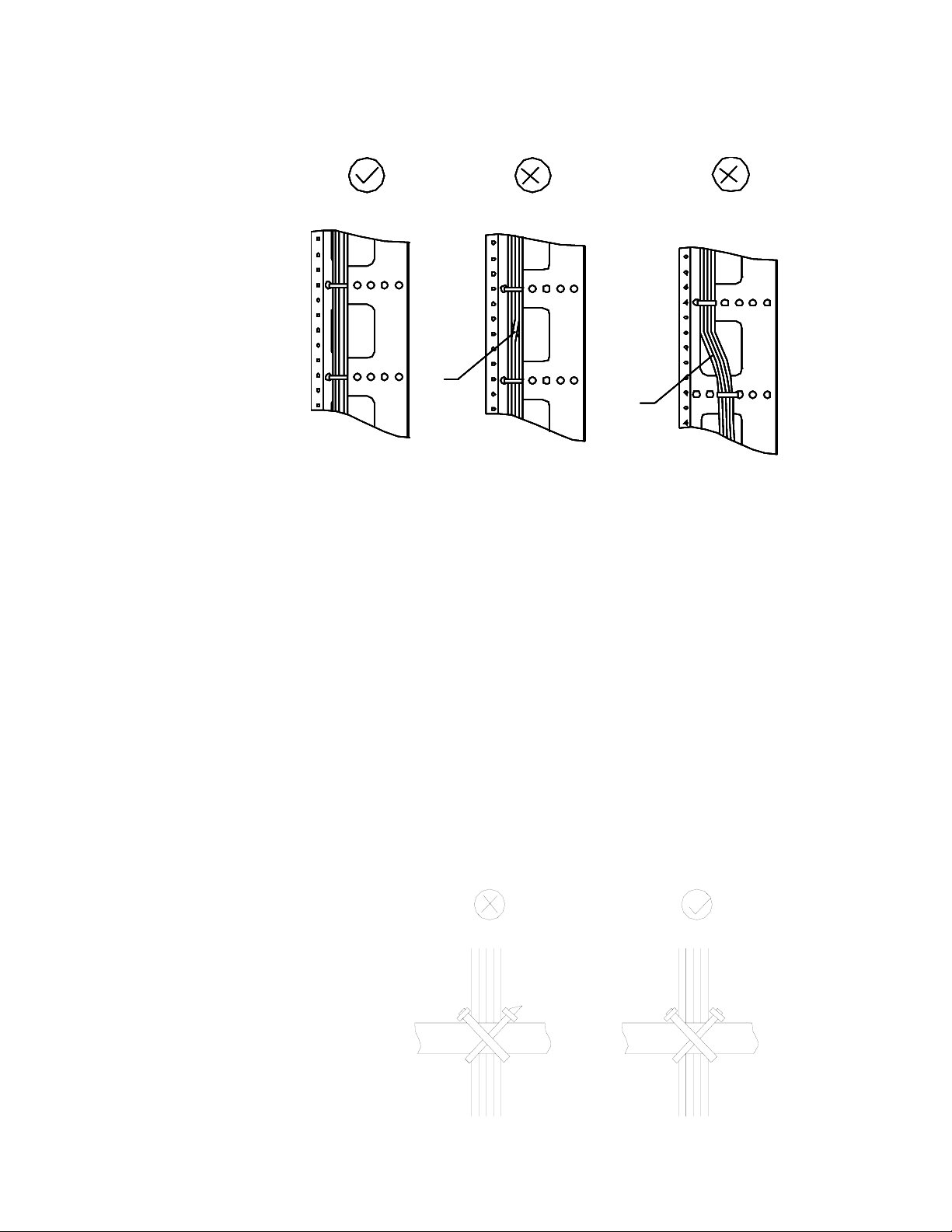
Cable Management 69
Figure 51 Cable bundling example I
Intertwined
Intertwined
Bent
Bent
■ The bending radius of cable body cannot be less than twice of the cable
diameter. The bending radius of the cable cannot be less than 5 times of its
diameter at the place where it is led out of the connector;
■ Different cables (power cord, signal cable, PGND wire, etc.) should be cabled
and bundled separately rather than together in the cabinet. If they are close to
each other, you can cable them in cross-shape. For parallel cabling, the space
between power cord and signal cable should be no less than 30 mm (1.2 in);
■ The cable binding rack and cabling channel inside and outside the cabinet
should be smooth and without sharp edges or tips;
■ The metal cable management hole should have a smooth and fully rounded
surface or wear a insulating bush;
■ Use the right type of ties to bundle the cables. Do not bundle cables with
joined ties. 3Com Corporation provides the following types of ties: 100 x 2.5
mm (3.9 in x 0.1 in), 150 x 3.6 mm (5.9 x 0.1 in), 300 x 3.6 mm (11.8 x 0.1 in),
530 x 9 mm (20.9 x 0.4 in), and 580 x 13 mm (22.8 x 0.5 in);
■ Cut the extra parts of the ties neatly after bundling the cables, leaving no sharp
or angular tips. See the following figure:
Figure 52 Cable bundling example II
Page 70

70 CHAPTER 4: SWITCH INSTALLATION
■ Bundle the cables wherever cable bending cannot be avoided. However, the
Figure 53 Cable bundling example III
■ The spare cables or excessive cable parts should be folded and bundled and
cable ties cannot be placed inside the bending area in case of the likelihood of
cable core break due to excessive stress. See the following figure.
placed at a right place in the cabinet or on the cabling channel. A “right place”
refers to the place where the cables will not affect the operation of the device
or impair the device, or be damaged;
■ The power cords cannot be tied on the guides of any mobile components;
■ Reserve some redundancy for the cables connecting to the mobile parts, the
PGND wire of the door for example, to free the cables from possible stress.
Such a mobile part should be installed in such a way that the extra cable
segments will be kept from contacting the heat source, sharp points or edges.
Use high temperature cables near the heat sources;
■ For the cable terminals fixed using screw threads, the screws or nuts should be
securely fastened and prevented from loosing. See the following figure;
Figure 54 Cable fixing example
Flat
Flat
washer
washer
Flat
Flat
washer
washer
Spring
Spring
washer
washer
Nut
Nut
Page 71

Verifying the Installation 71
■ When using a hard power cord, fix it near its terminal so as to free the terminal
and the cable from stress;
■ Do not use tapping screws to fasten the connecting terminals;
■ The power cords of the same type and in the same direction should be bundled
together and kept neatly and straight;
The following table lists the requirements in the bundling with cable ties.
Ta bl e 71 Tie-binding parameters
Cable bundle diameter (mm) Space between bundles (mm)
10 80 to 150
10 to 30 150 to 200
30 200 to 300
■ No cable or bundle can tie a knot;
■ The metal parts of the crimped cold-pressed terminal blocks (such as air switch)
cannot stretch beyond the blocks.
Verifying the Installation
c
CAUTION: Confirm that you have turned off the power before checking,
otherwise, improper connection will hurt people or impair the components of the
switch.
After installing the switch, verify the installation by the following list, ensuring all
the checking results are normal.
Ta bl e 72 Installation checking list
Item Normal Abnormal (Description)
ESD-preventive wrist strap
Console cable
PGND wire
Power cord
fabric
I/O module/Application
Module
Fan tray
PSU
Page 72

72 CHAPTER 4: SWITCH INSTALLATION
Page 73
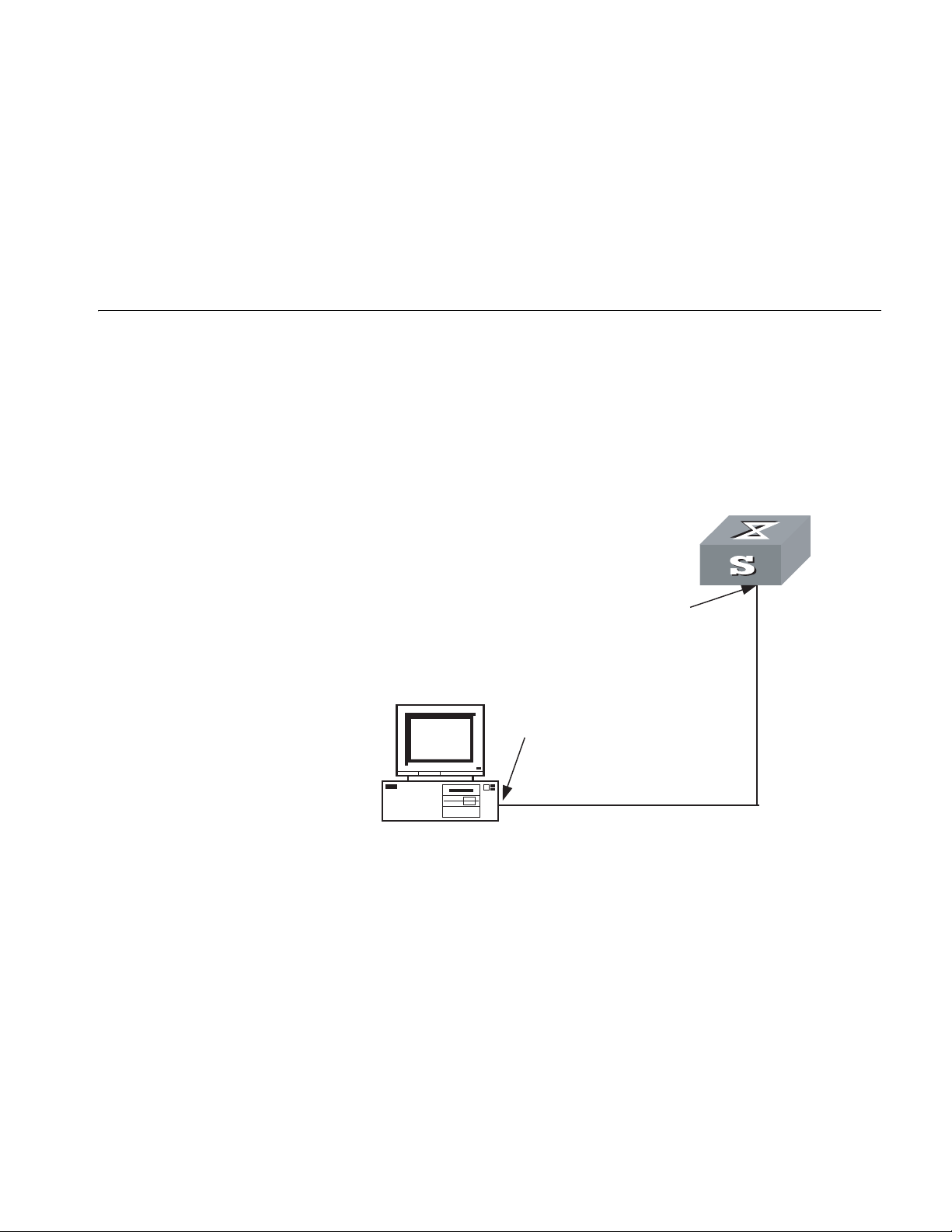
5
Setting up Configuration Environment
SYSTEM DEBUGGING
Setting up
Configuration
Environment
Connect a terminal (a PC in this scenario) to the switch with a Console cable.
Figure 55 Networking environment for switch configuration
Switch
To the console port
To the serial port
Console cable
PC
Connecting Cables Step 1: Insert the DB-9 (or DB-25) female connector of the Console cable into the
serial port on the PC (the Console terminal).
Step 2: Insert the RJ-45 connector of the cable into the Console port on the
switch.
Setting Terminal
Parameters
Set baud rate to 9600, data bits to 8, parity check to none, stop bits to 1, flow
control to none, and terminal emulation to VT100.
This section will tell you how to set the terminal parameters, taking a PC running
Windows 98 Hyper Terminal as an example.
Page 74

74 CHAPTER 5: SYSTEM DEBUGGING
Step 1: Start PC, and run terminal emulation program (such as Terminal of
Windows3.1, or Hyper Terminal of Windows 95/Windows 98/Windows
2000/Windows NT/Windows XP/Windows ME) on PC.
Step 2: Set parameters in the Hyper Terminal of Windows98.
You must set the baud rate to 9600, data bits to 8, no parity check, stop bit to 1,
and flow control to none, and select VT100 for terminal emulation. Specifically,
1 Click Start→Programs→Accessories→Communications→HyperTerminal to
access the Hyper Terminal window. The Connection Description dialog box
displays.
2 Click the red phone icon in the window to set up a new connection.
3 Enter the name of the new connection in the Name field and OK. The Properties
dialog box displays.
4 Select the target serial port to be used in Connect using field, and click OK. The
Port Settings Properties dialog box display.
5 Set the connecting serial interface parameters. Set the bits per second to 9600,
data bits to 8, Parity to None, stop bits to 1, and flow control to None, then click
OK. The HyperTerminal dialog box displays.
n
Powering and Booting the Switch
Verifying Installation
before Powering the
Switch
6 Select File→Properties to access the 3Com Properties Window.
7 Click the Settings tab, select VT100 for terminal emulation, and click OK to
confirm the settings.
It is recommended that you set the function, arrow, and Ctrl keys to act as
Windows keys.
You should verify the installation of the switch before powering it on, to make
sure that:
■ The switch is stable enough.
■ All the boards have been correctly installed.
■ All the communication cables, fibers, power cords, and grounding wires are
correctly connected.
■ The proper power voltage is used as required by the switch.
■ The Console cable has been correctly connected, the PC or terminal for
configuration has been in service and all the required terminal parameters have
been set.
c
Powering on the Switch ■ Turn on the power switch of the power source providing power to the switch.
CAUTION: Before powering on the switch, locate the position of the power
switch for the equipment room where you will operate so that you can switch off
the power supply promptly if needed.
■ Turn on the power switch.
Page 75

Powering and Booting the Switch 75
Verifying after Power-on
(Recommended)
Boot Interface The Switch 8807 is used as an example in this section.
To ensure the configuration works that you will make on the switch, you are
recommended to check the switch after powering it on to make sure that:
■ The cooling system is working. In this case, you can hear the noise caused by
fan rotation and feel that there is air exhausted out.
■ All the system LEDs on the fabrics function normal.
The following is the information that will be output at the Console terminal when
you power on the switch.
ZBB_TEST
Starting...
******************************************
* *
* 3Com Switch 8800 Family Bootrom, Version 106 *
* *
******************************************
Copyright(C) 2001-2005 by 3Com CORPORATION
Creation date: Jun 6 2003, 19:28:01
CPU type : MPC755
CPU L2 Cache : 1024KB
CPU Clock Speed : 400MHz
BUS Clock Speed : 100MHz
Memory Size : 512MB
Flash file system init....done
Switch 8800 Family 3C17508 board self testing.....................
The board is steady
SlotNo of this 3C17508 is 0
BootRom main system CRC check is OK
82559 register testing is OK
EPLD1 testing is OK
EPLD2 testing is OK
16c2552 register testing is OK
Please check LEDs......................LED testing finished
The switch Mac address is 00e0.fc00.00a1
Press Ctrl+B to enter Boot Menu... 0
Auto-booting...
Booting from Flash...
Decompress Image...................................................
.......................................................OK!
Starting at 0x10000...
User interface Con 0 is available
Press ENTER to get started.
n
The above prompt information appears when the switch completes its boot
sequence. Press Enter to begin configuring the switch.
The Switch 8800 Family provide abundant command views. For more information
about the configuration commands and the Command Line Interface (CLI), see
3Com Switch 8800 Family Routing Switches Operation Manual.
Page 76

76 CHAPTER 5: SYSTEM DEBUGGING
Page 77

SWITCH MONITORING AND
6
MAINTENANCE
Monitoring the Switch Although the Switch 8800 Family has undergone a comprehensive and strict
factory test before delivery, there might be some fault occurring due to improper
installation. This chapter describes how to troubleshoot the Switch 8800 Family.
Troubleshooting Console
Te rm in al
If the system is normal after the Switch is powered on, the booting information
will be displayed on the Console terminal. If the configuration system has failed,
the Console terminal may give illegible output or nothing at all.
1 The terminal gives no displays after the Switch is powered on.
In this case, you should check if:
■ The power system is working normally.
■ The fabric is working normally.
■ The Console cable has been connected to the Console port on the fabric.
If no problem has been found in the above checking, the symptom is very likely
caused by the errors listed below.
Troubleshooting PSU
■ The Console cable is not connected to the right serial port, that is, the port in
use is not the one configured on the terminal.
■ There are Console terminal parameter errors. (According to the parameter
setting requirements, you should set the baud rate to 9600, data bits to 8,
parity to None, stop bits to 1, flow control to None, and select VT100 as
terminal emulation.)
■ The Console cable is not in good condition.
2 The terminal gives illegible characters.
This symptom is very likely caused by a Console terminal setting error. In this case,
check that you have set the baud rate to 9600, data bits to 8, parity to None, stop
bits to 1, flow control to None, and select VT100 as terminal emulation.
Ta bl e 73 Description of the LEDs on PSU
LED Description
INPUT It keeps ON if the power input is normal and the PSU switch is at ON position. It
keeps OFF if the power input has failed or if there is no power input at all.
OUTPUT It keeps ON if the power output is normal and OFF in any other cases.
FAIL It keeps ON if the PSU has failed and OFF in any other cases.
Following are the PSU faults that likely appear and the methods used for problem
isolation.
Page 78

78 CHAPTER 6: SWITCH MONITORING AND MAINTENANCE
■ The Input LED (green) and Output LED (green) stay ON, but the display power
command shows that the PSU is not in position (but the other PSU operates
normally). Such a problem is likely caused because of the poor contact
between the PSU and the backplane due to a badly seated PSU. In this case,
switch off the power supply, loosen the captive screws on the PSU, push the
PSU into the chassis a little bit, tighten the captive screws, and switch on the
power supply to check that the normal state is resumed.
■ The Input LED (green) and Output LED (green) are OFF. In this case, check that
the power cords are connected correctly, the power cords are in good
condition, and the power switch has been put in the ON position.
■ The Fail LED (red) is ON. In this case, check that the correct power voltage is in
use (i.e., 90 to 264VAC, 50-60 Hz for AC PSU).
■ The Fail LED (red) is ON. In this case, check that the air filter protecting the fan
tray is clean. Excessive dust accumulated on the air filter will block the fan tray
from free ventilation and even lead to power supply failure.
■ If you cannot solve the problem yet after going through the above checking
steps, contact 3Com technical support engineers rather than disassembling the
PSU yourself.
Troubleshooting Fan
Tray
n
The Switch 8800 Family provides two LEDs on the fan tray. You can read them and
know if the fan tray is OK.
Ta bl e 74 Description of fan tray LEDs
Indicator State description
RUN Green indicates that the fan tray is normally operating.
OFF indicates that the fan tray has failed.
ALM Red indicates that the fan tray has failed.
OFF indicates that the fan tray is in normal state.
The ALM LED on the fan tray keeps ON for 2 to 3 seconds when the switch is
powered on.
If the RUN LED is OFF, check if:
■ The fan tray has been well seated.
■ All the cables connecting the fan tray and the backplane have been correctly
connected and are in good condition.
■ The fans are working normally.
■ The rotation of the fans has not been blocked.
■ The blank filler panels have been inserted into those I/O module slots.
Troubleshooting I/O
Module
The Switch 8800 Family provides I/O moduleX LEDs on the fabric for the user to
observe the state of these I/O modules.
Page 79

Hardware Maintenance
Hardware Maintenance 79
Ta bl e 75 Description of I/O module LEDs
Indicator State description
RUN ON indicates I/O module failure.
OFF indicates that the I/O module has failed or it is not in position
at all.
Blinking indicates that the I/O module is working normally.
ALM OFF indicates that there is no I/O module alarm or the I/O module is
not in position at all.
ON indicates that there is I/O module alarm.
2~6 (Switch 8807)
0~3, 6~9 (Switch 8810)
0~5, 8~13 (Switch 8814)
On Switch 8807, I/O module 0 through I/O module 4 respectively
correspond to slots 2 through 6.
On Switch 8810, I/O module 0 through I/O module 7 respectively
correspond to slots 0 through 3 and 6 through 9.
On Switch 8814, I/O module 0 through I/O module 11 respectively
correspond to Slots 0 through 5 and 8 through 13.
Replacing AC PSU
c
CAUTION: The PSU of the Switch 8800 Family is hot-swappable.
When installing or replacing a PSU while power is being supplied, you must take
care in the operation procedures and safety with electricity. Do not touch any
naked wires, terminals or any parts of the product marked with a dangerous
voltage label to avoid bodily injury.
Removing AC PSU (Switch 8807 as example)
Step 1: Put the power switch on the PSU from the ON position into the OFF
position.
Step 2: Pull right the clamp holding the power cord connector and unplug the
power cord.
Step 3: Unscrew the captive screws on the both sides of the PSU panel with a
flathead screwdriver.
Step 4: Hold the handle of the PSU and pull the PSU gently out of the chassis
along the guides.
Page 80
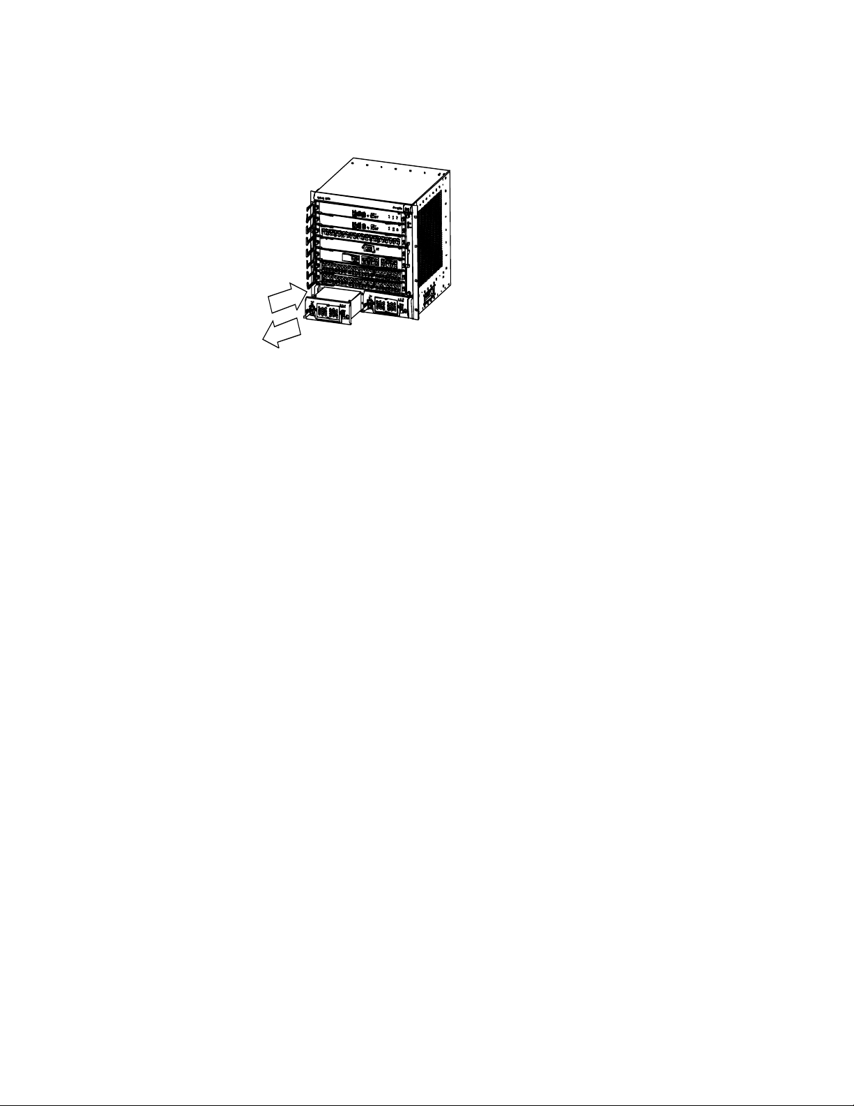
80 CHAPTER 6: SWITCH MONITORING AND MAINTENANCE
Figure 56 Remove and install the AC PSU
You can remove AC PSU from the 8810/Switch 8814 in similar way.
c
CAUTION:
■ The Switch 8800 Family uses multiple power systems, and you must turn off all
of them when removing the AC PSU.
■ As the PSU of the Switch 8800 Family is heavy, use both hands to pull it out
slowly and gently, with one holding its handle and the other holding its
bottom.
■ If you do not want to install a PSU, insert a blank filler panel into the PSU slot
for dust-proofing and guaranteeing ventilation.
Installing AC PSU (Switch 8807 as example)
Step 1: Hold the handle of the PSU with one hand and the bottom of the PSU with
another hand, and gently slide the PSU into the chassis along the guides until it
mates the backplane well.
Step 2: Fasten the captive screws at both sides of the PSU panel with a flathead
screwdriver.
Step3: Check that the power switch on the panel is in the “OFF” position and the
clamp holding the power cord connector has been pulled up.
Step 4: Insert the AC power cord accompanied the Switch into the socket on the
PSU.
Replacing and Cleaning
the Air Filter of PSU
c
Step 5: Pull the clamp down to hold the power cord.
You can install AC PSU to the 8810/Switch 8814 in same way.
The AC PSU air filter can be replaced.
CAUTION: We strongly recommend that you clean the air filter semimonthly to
guarantee adequate ventilation.
Page 81
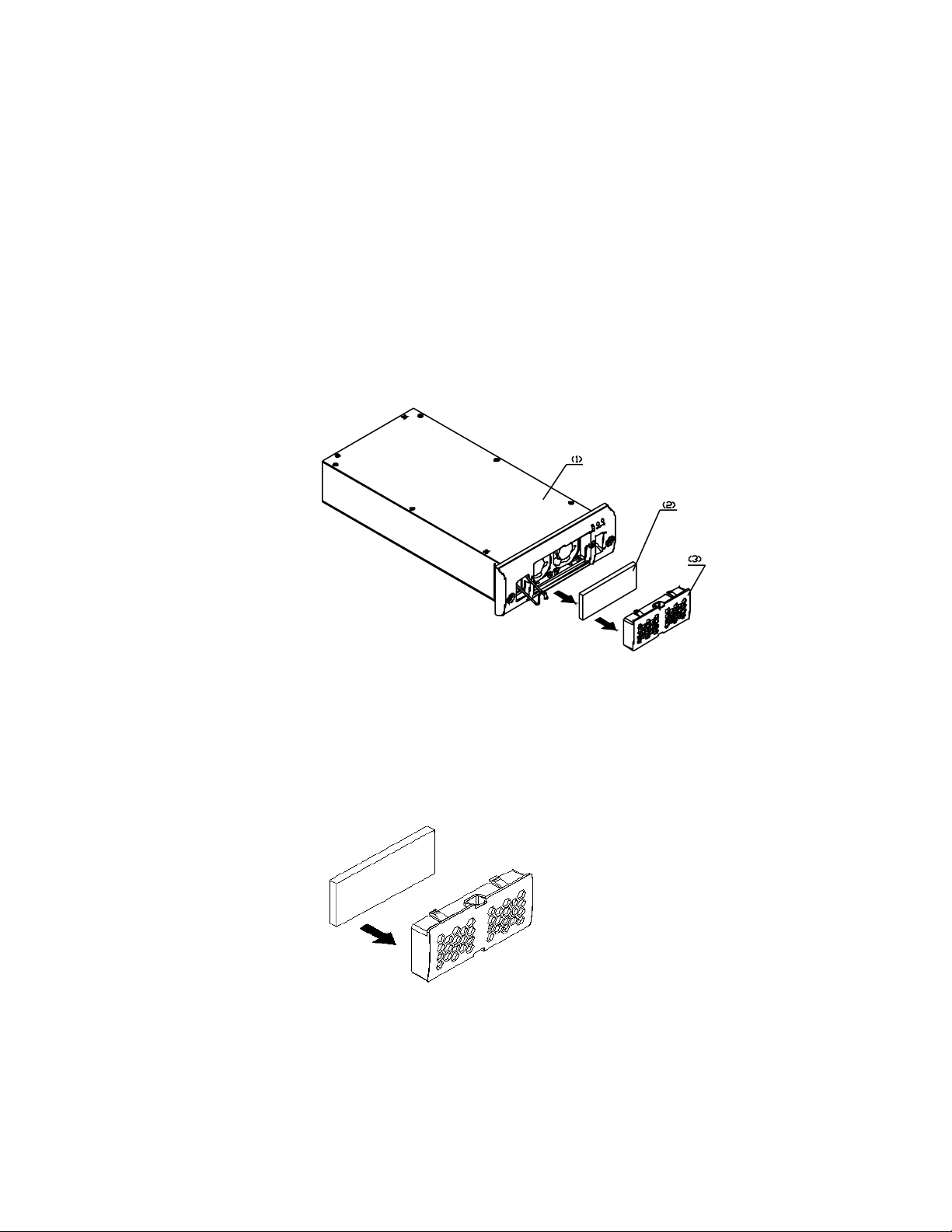
Hardware Maintenance 81
Removing and cleaning the air filter of PSU
Step 1: Clutch the air filter by the upper and lower edges with your index finger
and the thumb.
Step 2: Pull the air filter out with an even strength.
Step 3: Take the black air filter mesh out.
Step 4: Clean the mesh and dry it, taking care not to rub it.
Step 5: Place the dry black mesh back in position again.
Figure 57 Remove the air filter of AC PSU
(1) PSU (2) Air filter (3) Air filter cover
Installing the air filter of PSU
Step 1: Check that the black mesh has been nested in the air filter cover. If not, go
ahead to do that.
Figure 58 Install the air filter of PSU I
Step 2: Clutch the air filter cover by the upper and lower edges with your index
finger and thumb and push it inside the PSU with an even strength.
Page 82

82 CHAPTER 6: SWITCH MONITORING AND MAINTENANCE
Replacing and Cleaning
the Air Filter of Chassis
c
c
CAUTION: You are strongly recommended to clean the air filter semimonthly to
guarantee adequate ventilation.
The air filter of the Switch 8800 Family is installed at the air intake vents of the
chassis. If you do not clean the air filter often, the dust accumulated on it will
block the holes of the filter, hence affecting the ventilation of the chassis. For this
reason, you are recommended to clean the air filter at a proper interval.
Both methods of dry-clean and rinsing are allowed. However, take care not to rub
the air filter when you wash it, and simply air it after that.
Removing and cleaning the air filter of chassis
Step 1: Unscrew the captive screws at the top and bottom of the air filter with a
flathead screwdriver.
Step 2: Hold the air filter at the left-rear by its upper and lower edges, pull part of
it out of the chassis, put one hand underneath the air filter to hold it, and pull it
out slowly along the guides.
CAUTION: As the air filter is rather long, you should hold its front end with one
hand, and bear its weight by putting another hand underneath it when sliding the
air filter out of the chassis.
Step 3: Rather than taking the air filter mesh out, directly wash the air filter after
removing it from the chassis, air it, and insert it into the chassis again.
Installing the air filter of the chassis
Step 1: Hold the front end of the air filter with one hand and put another hand
underneath it, align it with the guides, and slide it into the chassis along the
guides.
Step 2: Fix the air filter by fastening the captive screws at the top and bottom of
the air filter with a flathead screwdriver.
c
Replacing a Module The fabric, I/O modules, and Application Modules of the Switch 8800 Family are in
CAUTION: As the air filter is rather long, you should hold its front end with one
hand, and bear its weight by putting another hand underneath it when sliding the
air filter into the chassis.
similar structure and can be installed and removed almost in the same way. This
section describes the general procedures for removing and installing these
module.
The Switch 8800 Family modules are hot-swappable.
Required tools
■ ESD-preventive wrist strap
■ Screwdriver
Page 83
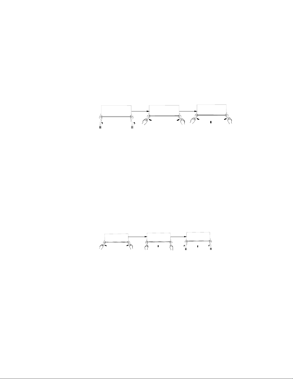
Hardware Maintenance 83
Removing a module
Step 1: Wear the ESD-preventive wrist strap and unscrew the captive screws on
the module with a flathead screwdriver.
Step 2: Hold the ejector levers on the module with both hands and press them
outward to separate the locking pin of the module from the backplane.
Step 3: Gently pull the module out of the slot along the guides.
Figure 59 Removing a Module
Installing a Module
Step 1: Wear the ESD-preventive wrist strap and unscrew the mounting screws
fixing the blank filter panel in the slot where you want to install the module, and
remove the blank filler panel.
Replacing the Fan Tray
c
Step 2: Hold the ejector levers of the card with both hands and pull them outward,
align the card with the guides in the chassis, and slide it gently into the slot until
its positioning pin touches the positioning hole in the chassis.
Step 3: Pull the ejector levers inward to lock the positioning pin of the card into
the positioning hole in the chassis.
Step 4: Fasten the captive screws to fix the card.
Figure 60 Installing a Module
CAUTION: Do not touch naked wires, terminals or the switch parts where
dangerous voltage warning is given to avoid bodily injury.
Required tools
■ ESD-preventive wrist strap
■ Screwdriver
Replacing the fan tray
Step 1: Wear the ESD-preventive wrist strap. Screw off the captive screws on both
sides of the fan tray. Pull the fan tray outward with one hand contacting the
switch top and the other hand around the handle of the fan tray to separate the
fan tray positioning pin from the backplane.
Page 84

84 CHAPTER 6: SWITCH MONITORING AND MAINTENANCE
c
c
CAUTION: When you replace the fan tray of an operating switch, pull the fan tray
out from the chassis only after the fans stop rotating. In this case, there is still the
possibility that fans are still rotating. Therefore do not put your hand into the fan
tray to avoid bodily injury.
Step 2: Gently pull the fan tray out of the slot along the guides.
Step 3: Put the removed fan tray into the packing bag.
Step 4: Hold the handle of the fan tray with one hand and its bottom with the
other and pull them outward. Align the fan tray with the guides in the chassis and
slide it gently into the slot until its positioning pin touches the positioning hole in
the chassis.
Step 5: Screw on the captive screws on both sides of the fan tray.
CAUTION: Install a new fan tray soon after removing the old one to ensure the
normal working of the Switch.
Software Upgrade
Upgrade preparations The Switch 8807 and Switch 8810 software can be maintained in the same way as
that for the Switch 8814, so Switch 8814 is used as an example in the following
software maintenance process.
Required cables
■ Console cable (for serial interface)
■ One crossover and one standard network cables
■ Debug cable (for serial interface)
Recommended upgrade procedure
1 Confirm if the host program has loaded before initiating software upgrade.
2 Check the current version of the host and Boot ROM programs.
3 Back up the current host program, Boot ROM program and configuration file (to
PC recommended), for possible rollback in case of failed upgrade.
4 Load the host and Boot ROM program files to the switch. If the switch has two
fabrics, you also can copy the host and Boot ROM program files to the standby
fabric.
5 Upgrade the Boot ROM program on the fabric and I/O module (optional).
6 Specify the next boot program. If the switch has two fabrics, specify the load
programs respectively for the active and standby fabrics.
7 Reboot the switch.
8 Check if the board version is correct.
You can load the software through command line interface (CLI) and Boot menu.
1 Local loading using Boot menu:
■ Loading using XModem and through Console port
Page 85

■ Loading using TFTP and through Ethernet port
■ Loading using FTP and through Ethernet port
2 Local or remote loading through CLI:
■ Loading using FTP
■ Loading using TFTP
Software Upgrade 85
Local Loading through
Boot Menu
Boot menu
After powering on the Switch, run Boot ROM program first and the terminal will
display the following information:
ZBB_TEST
Starting...
*************************************************
* *
* 3Com Switch 8800 Family Bootrom, Version 109
*
* *
*************************************************
Copyright(C) 2001-2005 by 3Com CORPORATION
Creation date: Dec 9 2003, 16:19:42
CPU type : MPC755
CPU L2 Cache : 1024KB
CPU Clock Speed : 400MHz
BUS Clock Speed : 100MHz
Memory Size : 512MB
Flash file system init....done
Board type: Switch 8800 Family 3C17539
Board self testing...........................
The board is steady
SlotNo of this board is 6
The MCX is exist
BootRom main system CRC check is OK
82559 register testing is OK
EPLD1 testing is OK
EPLD2 testing is OK
16c2552 register testing is OK
Please check LEDs......................LED testing finished
The switch Mac address is 00e0.fc00.1111
Press Ctrl+B to enter Boot Menu... 5
Password :
n
Press <Ctrl+B> as prompted and the system will display:
Password :
To enter the Boot menu, you must press <Ctrl+B> within five seconds after the
appearance of the prompt “Press Ctrl-B to enter Boot menu...”. Otherwise, the
program decompression process will begin. To access the Boot menu after the
Switch enters the program decompression process, you need to restart the Switch.
Enter the correct Boot ROM password (no password has been set for the switch by
default), and the system will access the Boot menu:
Page 86
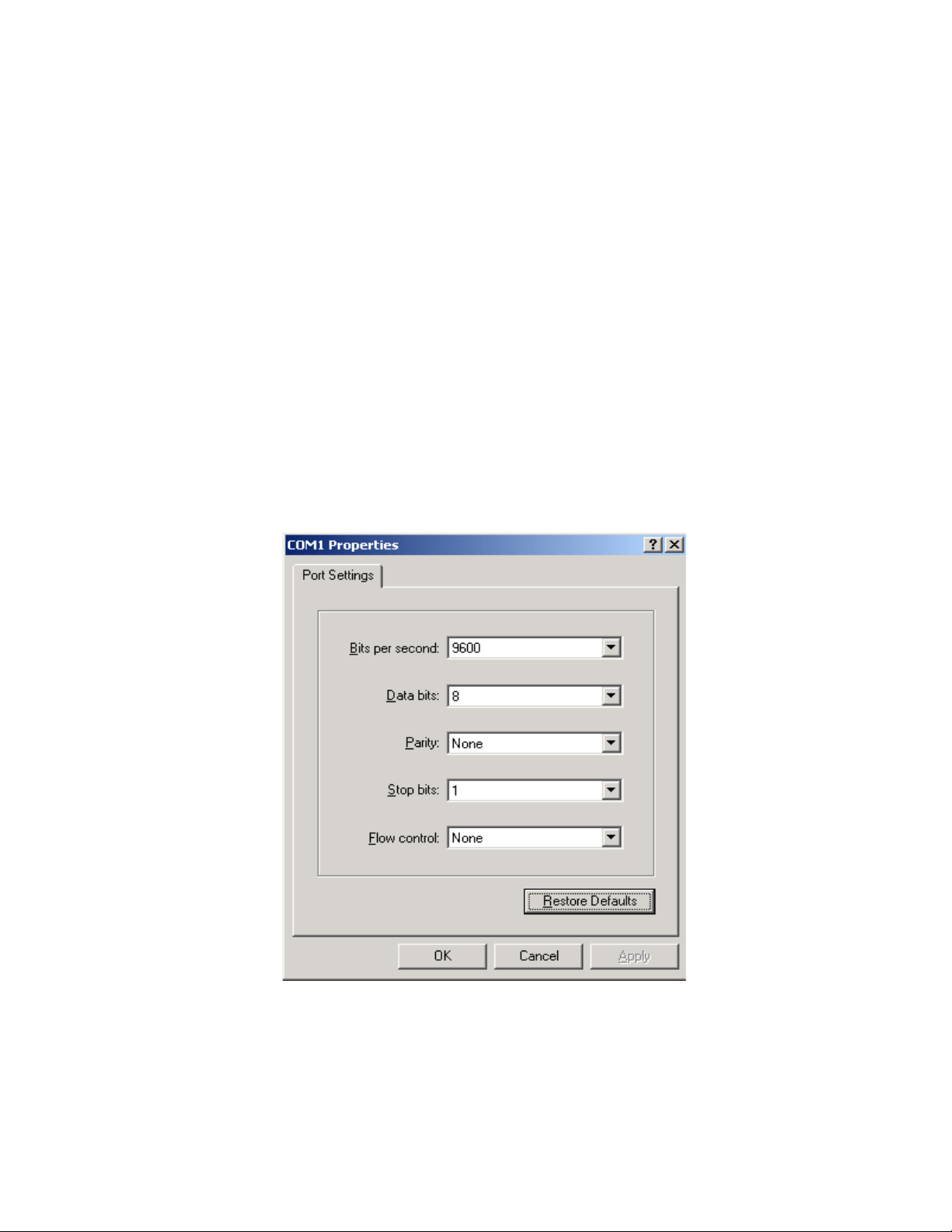
86 CHAPTER 6: SWITCH MONITORING AND MAINTENANCE
c
n
CAUTION: While using the Switch, keep in mind the latest Boot ROM password.
MAIN MENU
1. Boot with default mode
2. Boot from Flash
3. Boot from HardDisk
4. Enter serial submenu
5. Enter ethernet submenu
6. Modify Flash description area
7. Modify bootrom password
0. Reboot
Enter your choice(0-7):
You must ensure the upgraded host program is compatible with the existing Boot
ROM program of the I/O module. Otherwise, you have to upgrade it during host
program upgrade.
When loading the host program through the Boot menu, you must configure
correct attributes of the serial interface (as shown in
Hyper Terminal does not respond.
Figure 61 Attribute settings of Hyper Terminal serial interface
Figure 61). Otherwise, the
Upgrading software through console port (XModem)
1 Brief introduction to XModem
XModem, a type of file transfer protocol, is broadly applied for its simplicity and
good performance. It transmits files through serial interfaces, supporting 128
bytes and 1Kbytes in terms of data unit, checksum and CRC in terms of checking
mode, and multiple retransmissions (usually ten attempts) in the event that packet
errors are found.
Page 87

Software Upgrade 87
XModem completes transmission by the receiving program (receiver) and the
sending program (sender). In XModem, the transmission begins with the sending
of negotiation characters from the receiver for the purpose of check mode
negotiation. After passing the negotiation, the sender is allowed to send the first
data packet. Upon the receipt of the complete packet, the receiver checks the
packet using the agreed checking mode and will send an ACK if the packet has
passed the check and a NAK if not. Receiving the ACK, the sender will send the
next packet; receiving the NAK instead, the sender will retransmit the previously
sent packet.
2 Xmodem application
Step 1: In the Boot menu, enter 4, press Enter, and the system will access the
serial interface submenu:
SERIAL SUBMENU
1. Download file to SDRAM through serial interface and boot
2. Download file to Flash through serial interface
3. Download file to HardDisk through serial interface
4. Modify serial interface boot parameter
0. Return to main menu
Enter your choice(0-4):4
Step 2: Enter 4 in the serial interface submenu and press Enter to access the
following interface for setting the parameters of the downloading serial interface:
1: 9600(default)
2: 19200
3: 38400
4: 57600
5: 115200
please select an appropriate baudrate:
Enter your choice(1-5): 5
Step 3: Select the appropriate downloading speed as needed. For example, enter 5
to select the downloading speed of 115200 bps, press Enter, and the system will
display the following information in the terminal:
BaudRate is 115200 bps. Please change the terminal’s speed to 115200
bps
Step 4: At the prompt displayed in the last step, change the baud rate on the
Console terminal to the same one selected for software downloading, disconnect
the terminal and connect it again, press Enter, and the terminal will access the
serial interface submenu again:
SERIAL SUBMENU
1. Download file to SDRAM through serial interface and boot
2. Download file to Flash through serial interface
3. Download file to HardDisk through serial interface
4. Modify serial interface boot parameter
0. Return to main menu
Enter your choice(0-4):2
n
■ After changing the baud rate, you must close the terminal emulation program
and start it again for at least once in order to validate the new baud rate.
■ In a Windows 98 operating system environment, you can perform the
operations of disconnection and reconnection after changing the baud rate. In
a Windows 2000 operating system, however, you must disconnect the terminal
before setting the baud rate and connect the terminal after finishing the work.
Page 88
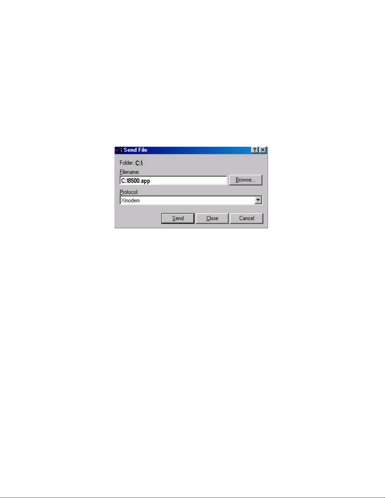
88 CHAPTER 6: SWITCH MONITORING AND MAINTENANCE
Step 5: Select a right place to store the downloaded file as needed. For
example, enter 2 at the prompt displayed in the last step to download the file
into the Flash of the switch, press Enter, and the system will display the
following information on the terminal:
Please Select File .
XMODEM downloading ...CCC
Step 6: Select [Transfer/Send File] in the terminal window. Click on <Browse> in
the pop-up dialog box (shown as the following figure), select the desired
application, and change the protocol used for downloading to XModem.
Figure 62 Send File dialog box
Step 7: Click Send. The Xmodem dialog box displays.
Step 8: After downloading the program successfully, the system begins to write
the data into the Flash. The downloading operation will end upon a successful
write operation. Then, the system will access the serial interface submenu
again, and the user can make selection as needed. The details will not be
covered here.
XMODEM downloading ...CCC download successfully!
flash:/ s8500.app already exist,
delete it?(Y/N):y
Deleting file------------------------------------------------------
---------------------------------------------------------------Done
Free flash Space : 15862784 bytes
Writing flash------------------------------------------------------
-------------------------------------------------------Done
SERIAL SUBMENU
1. Download file to SDRAM through serial interface and boot
2. Download file to Flash through serial interface
3. Download file to HardDisk through serial interface
4. Modify serial interface boot parameter
0. Return to main menu
Enter your choice(0-4):
Upgrading software through management Ethernet port (TFTP)
1 Introduction to TFTP
Trivial file transfer protocol (TFTP) is well suited to the file transfer between a server
and a client that do not need complex interaction.
In TFTP, the transmission is initiated by the client. When downloading a file, the
client sends a read request packet to the TFTP server, receives the data packets
from the server, and sends the ACK to the server. When uploading a file, the client
Page 89

Software Upgrade 89
sends a write request packet to the TFTP server, then sends the data packets to the
server, and receives the ACK from the server. The TFTP transmission files have two
forms, i.e., binary for program transmission and ASCII for text transmission.
Following is the upgrading procedure described taking the Switch 8814 working
as a TFTP Client as an example.
2 TFTP upgrade procedure
Step 1: Connect the Switch to a PC where the desired file is located via the
management/upgrade Ethernet port. (In this case, you should know the IP address
of the PC. At the same time, connect the Switch to an external PC (that can be the
same one that contains the desired file) via the Console port.
Step 2: Run the TFTP Server program on the PC connected to the
management/upgrade Ethernet port, and specify the path for upgrading the
application files.
Step 3: Run the terminal emulation program on the PC connected to the Console
port, and boot the switch to access the Boot menu.
Step 4: Enter 5 in the Boot menu. Press Enter and the system will access the
download application program menu.
ETHERNET SUBMENU
1. Download file to SDRAM through ethernet interface and boot
2. Download file to Flash through ethernet interface
3. Download file to HardDisk through ethernet interface
4. Modify ethernet interface boot parameter
0. Return to main menu
Be sure to select 4 to modify boot parameter before downloading!
Enter your choice(0-4): 4
n
Step 5: Enter 4 in the download application program menu to select TFTP for the
software upgrading. Press Enter and then you can begin to set the related TFTP
parameters:
Note: Two protocols for download, tftp & ftp.
You can modify the flags following the menu.
tftp--0x80, ftp--0x0.
The information above prompts you to set the flags to 0x80 when you download
files using TFTP and to 0x0 if using FTP.
’.’ = clear field; ’-’ = go to previous field; ^D = quit
boot device :fei0
processor number :
host name : 8500 ,
file name : 8500.app
inet on ethernet (e) : 1.1.1.1
inet on backplane (b):
host inet (h) : 1.1.1.2
gateway inet (g) :
user (u) :
ftp password (pw) (blank = use rsh):
flags (f) :0x80
target name (tn) :
startup script (s) :
other (o) :
Write flash...done!
Page 90

90 CHAPTER 6: SWITCH MONITORING AND MAINTENANCE
Step 6: After you provide the required information, the system accesses the
Ethernet interface submenu again:
ETHERNET SUBMENU
1. Download file to SDRAM through ethernet interface and boot
2. Download file to Flash through ethernet interface
3. Download file to HardDisk through ethernet interface
4. Modify ethernet interface boot parameter
0. Return to main menu
Enter your choice(0-4): 2
Step 7: At the prompt displayed in the last step, select a place for retaining the
downloaded file (the Flash for example by entering 2), press Enter, and the system
will display the following information in the terminal:
Attached TCP/IP interface to fei0.
Attaching network interface lo0... done.
boot device : fei0
unit number : 0
processor number : 0
host name : 8500
file name : 8500.app
inet on ethernet (e) : 1.1.1.1
host inet (h) : 1.1.1.2
flags (f) : 0x80
Prepare for loading....OK
Loading......done
flash:/s8500.app already exist,
delete it?(Y/N):y
Deleting file------------------------------------------------------
-------------------------------------------------Done
Free flash Space : 15862784 bytes
Writing Flash------------------------------------------------------
--------------------------------------------------------------------
--------------------------------------------------Done
Step 8: The information displayed in the last step means a successful file
downloading operation. In this case, the system accesses the Ethernet interface
submenu again and the user can make selection as needed. The details will not be
covered here.
ETHERNET SUBMENU
1. Download file to SDRAM through ethernet interface and boot
2. Download file to Flash through ethernet interface
3. Download file to HardDisk through ethernet interface
4. Modify ethernet interface boot parameter
0. Return to main menu
Enter your choice(0-4):
Upgrading software through management Ethernet port (FTP)
1 Introduction to FTP
The Switch 8800 Family applications can also be updated through the Ethernet
port and using FTP.
Following is the upgrading procedure, using the Switch 8814 working as an FTP
Client as an example.
2 Upgrade procedure
Page 91

Software Upgrade 91
Step 1: Connect the Switch to the PC containing the desired file via the
management/upgrade Ethernet port. (In this case, you should know the IP address
of the PC. At the same time, connect the Switch to an external PC (that can be the
same one that contains the desired file) via the Console port.
Step 2: Run FTP Server on the PC connected to the management/upgrade Ethernet
port, specify the path of the upgrading file, and set the login username and
password.
Step 3: Run the terminal emulation program on the PC connected to the Console
port, and boot the Switch to access the Boot menu.
Steps 4 ~ 8: See the corresponding steps in the upgrading procedure via TFTP for
reference.
n
Local or Remote Loading
through CLI
If you want to download files using FTP, please set the flags to 0x0 when setting
the Ethernet interface parameters.
After downloading the host program through the Boot menu, you must specify it
as the next boot program. In the following example, the host program is Switch
8800 Family-Comware 310-R1212.app.
MAIN MENU
1. Boot with default mode
2. Boot from Flash
3. Boot from CF card
4. Enter serial submenu
5. Enter ethernet submenu
6. Modify Flash description area
7. Modify bootrom password
0. Reboot
Enter your choice(0-7):
Enter your choice(0-7): 6
Please input ’0’ or ’1’ (’0’:Boot from Flash, ’1’:Boot from CF card)
BootDev = 0
FlashFileName = Switch 8800 Family-Comware 310-R1212.app
If your terminal is connected to the switch over a network, you can load Boot
ROM and host program at the remote through CLI.
Loading using FTP
Run FTP server on a local PC, provided you have configured username and
password and have set the correct file directory. Suppose IP address of the PC is
10.10.110.1. Log on to the switch using Telnet or through the Console port to
send host program to the switch using FTP.
Suppose that the main boot file is SWITCH002.app; the active host program is
SWITCH001.app; the Boot ROM program is SWITCHbtm.btm. You can follow
these steps after logging on to the switch.
Step 1: Download the software to the switch using FTP.
<3Com> 10.19.110.1
Trying ...
Press CTRL+K to abort
Connected.
220 WFTPD 2.0 service (by Texas Imperial Software) ready for new user
Page 92

92 CHAPTER 6: SWITCH MONITORING AND MAINTENANCE
User(none):8500
331 Give me your password, please
Password:
230 Logged in successfully
[ftp] get SWITCH002.app SWITCH002.app
[ftp] get Switchbtm.btm Switchbtm.btm
[ftp] bye
n
n
c
If the switch has two fabrics, you also can copy the host and Boot ROM program
files to the standby Fabric.
Step 2: Specify the next boot program. If the switch has two fabrics, specify the
load programs respectively for the active and standby fabrics. Suppose the current
standby fabric is at slot 7.
■ Load Boot ROM program
<3Com> boot bootrom flash:/Switchbtm.btm slot 6
<3Com> boot bootrom slot7#flash:/Switchbtm.btm slot 7
■ Load host program
<3Com> boot boot-loader flash:/SWITCH002.app
<3Com>boot boot-loader slot7#flash:/SWITCH002.app
The URL form of the files in the standby fabric file system must start with
“slot[No.]#flash:/”, where [No.] is the standby fabric number.
<3Com> display boot-loader
The app to boot of board 6 at the next time is: flash:/SWITCH002.app
The app to boot of board 6 at this time is: flash:/SWITCH002.app
The app to boot of board 7 at the next time is: flash:/SWITCH002.app
The app to boot of board 7 at this time is: flash:/SWITCH002.app
<3Com> reboot
CAUTION:
■ You must reboot the switch using the reboot command to validate the host
program. If Flash memory space is not enough, you can delete some of the
program files in Flash after completing the Boot ROM loading. (You are
recommended to delete the host program that is no longer in use.) Then
upload the host program to the switch using FTP.
Application Module
Program Upgrade
■ Make sure that you have saved other configurations before rebooting;
otherwise, they might not survive a reboot.
■ Power-off is forbidden during loading process.
Boot ROM and host program loading is completed now.
Remote and local loading using TFTP
Using TFTP is similar to using FTP in remote and local loading via commands. The
only difference is that you use the tftp get command to download software to
the switch. In this case, the switch can only be used as a TFTP client to download
the software to its Flash memory from the TFTP server. The remaining steps after
downloading are the same as those of remote loading using FTP.
If you have the 360G Fabric (3C17508), download the application software image
files to the compact flash (CF) and then boot from the CF.
Page 93

Password Loss 93
If you have the 720G Fabric (3C17539), download the application software image
files directly to the Fabric’s onboard flash.
Troubleshooting
Software Upgrade
These types of problems may occur during software upgrade:
No response from fabric serial interface
Check if the serial interface cable is in good condition and if its attributes are set
correctly.
Uploading configuration file or host program using FTP fails
Please check
■ If the configuration is correct and if the FTP server is started.
■ If the Flash has enough space for the target files.
■ If the TFTP flag is selected (TFTP is not supported).
No configuration saving during I/O module reboot
Before saving the configuration, you must check the operating status of the I/O
module. Do not save the configuration during the I/O module reboot. Otherwise,
the configuration you want to save may be lost.
I/O module program loading fails or you cannot register for a long period
■ Check I/O module type to see if this type is supported on the current host
program.
■ Check if the I/O module Boot ROM program matches the host program before
upgrade.
■ Check if I/O modules are well seated.
■ Insert an I/O module to different slots to check if it is OK.
■ Check if the host program exists and if the current host program is the running
one.
Insufficient Flash memory
■ Empty the recycle bin when the I/O module starts.
■ Delete the unused files in the Flash.
Password Loss If the Super password or Boot ROM password of the Switch is lost, please contact
your local support representative.
Page 94

94 CHAPTER 6: SWITCH MONITORING AND MAINTENANCE
Page 95
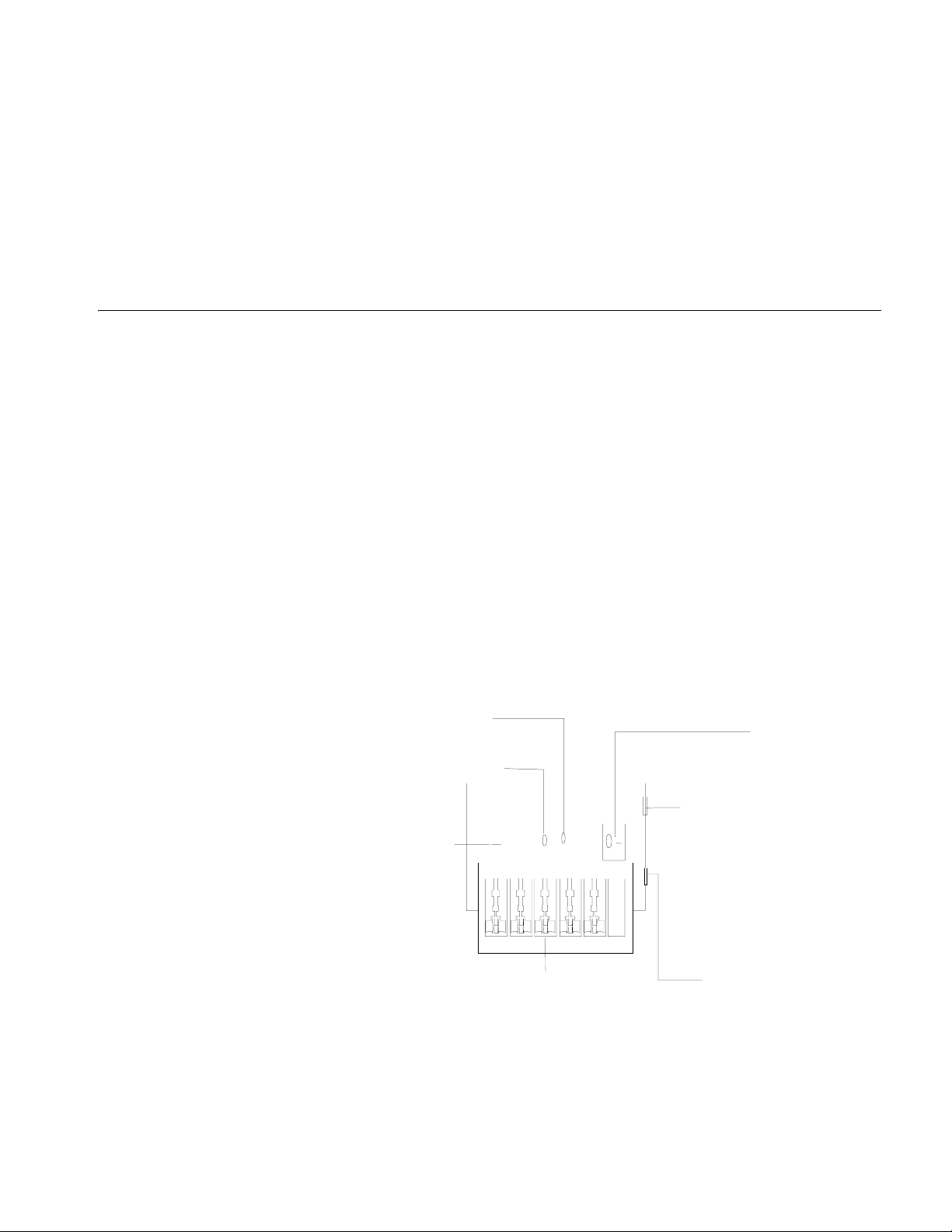
LIGHTNING PROTECTION OF THE
A
Installation of Lightning Arrester for AC Power (Socket Strip with Lightning Protection)
c
SWITCH
CAUTION: Lightning arrester will not be shipped with the switch. You should
purchase it by yourself if needed.
If an outdoor AC power cord should be directly led to the switch, please serially
connect the lightning arrester for AC power (Socket Strip with Lightning
Protection) before you plug AC power cord into the switch, thus to prevent the
possible damage to the switch due to lightning strike. You can use cable clips and
screws to fasten the lightning arrester for AC power on the cabinet, workbench or
the wall of equipment room.
Figure 63 Diagram of lightning arrester
c
Grounding and polarity indicator (red) :
On means that the lines are wrongly connected
(either the ground wire is not well connected, or the live and zero lines are wrongly connected).
Please check the power supply circuit.
Power switch
Normal operation indicator (green):
On means that the arrester works normally. Otherwise, it
means that the protection circuit has been damaged.
Power socket (complied with IEC standard),
connected to the power supply of the equipment
through power cord
Mainboard
Multipurpose power socket, connected to the device
CAUTION:
■ Make sure that the arrester is well grounded before using the lightning arrester
for power.
■ After inserting AC power cord plug of switch into the socket of lightning
arrester, if the green LED is on and the red LED does not alarm, it means that
protected by the arrester
Overload auto protector,
which can be manually reset.
Page 96

96 CHAPTER A: LIGHTNING PROTECTION OF THE SWITCH
the lightning arrester of power is running and the function of lightning
protection has taken effect.
■ Pay adequate attention if the red LED is on. You should correctly locate the
problem, whether it is caused because the ground wire of the arrester is not
well grounded or because the live and zero wires are connected in reverse
direction. You may check that in the following way. When the red LED is on,
use a multimeter to examine polarity at the power socket of the arrester. If it is
same to that of the power socket in the equipment room, it means that
arrester is not well grounded. If it is adverse to that of the power socket in the
equipment room, it means that the power socket of the arrester is set to the
reverse polarity. In this case, you should open the power socket of arrester to
correct polarity. After that, if the red LED still alarms, it means that the arrester
is not well grounded yet.
Installation of Lightning Arrester for Network Port
n
c
Lightning arrester for network port is specially designed for the Ethernet port of
10/100M electrical interface (RJ-45 connector is adopted in this case).
CAUTION: Lightning arrester for network port will not be provided along with the
switch, and you should purchase it by yourself if needed.
If an outdoor network cable should be led to the switch, please serially connect
the lightning arrester for network port before you plug this cable into the interface
on the switch, in case of the possibility that the switch may be damaged due to
lightning strike.
Required tools
■ Phillips screwdriver or Flat-module screwdriver
■ Multimeter
■ Tilted wire cutter
Installation procedure
Step 1: Tear the protection paper at one side of the double faced adhesive tape
apart from the tape, and stick the tape on the surface of the arrester. Tear the
protection paper at another side apart from the tape, and stick the arrester onto
the chassis of the switch. The arrester should be attached on the chassis as close
to the grounding screw as possible.
Step 2: According to the distance to the grounding screw of the switch, cut the
ground wire of the arrester, and securely tightening its ground wire to the
grounding screw of the switch.
Step 3: Use the multimeter to measure whether the ground wire of the arrester
contacts well with the grounding screw of chassis.
Step 4: According to the instruction of arrester for network port, connect the
arrester with switch by the cables (be carefully with the cable direction. Outdoor
network cable should be inserted into the arrester‘s IN end, and the cable
Page 97

Installation of Lightning Arrester for Network Port 97
r
connected to the switch should be inserted into the arrester’s OUT end). When
you do that, observe whether the arrester indicators normally display.
n
The instruction of lightning arrester for network port contains the technical
specifications, installation and maintenance guide of the arrester. Please carefully
read it before installing the arrester.
Step 5: Use the nylon ties to bundle the cables neatly.
Network cable indoors
Switch
Power input
Network cable led into from outdoo
Lightning arrester for network port
(attached onto the chassis)
Ground wire of lightning arrester
Grounding screw of switch
Metal cabinet that contains the
Installation precautions
Fully consider the following items in the installation process, otherwise, the
performance of the lightning arrester for network port will be affected:
■ Lightning arrester for network port is installed in reverse direction. In practice,
the “IN” end should be connected to the outdoor network cable and the
“OUT” end to the network port on the switch.
■ Lightning arrester for the network port is not well grounded. The ground wire
for the arrester should be as short as possible, so to ensure its good contact
with the grounding screw of the switch. After the connection, use the
multimeter to confirm that.
■ The lightning arrester for the network port is not installed completely. If the
switch has more than one network ports to interconnect with other devices via
cables outdoor, you should install lightning arresters for all these network ports
for protection.
 Loading...