


 Loading...
YASNAC PC NC
Connecting Manual
Version: Beta 1.0
YASNAC PCNC Connecting Manual |
Preface/Table of Contents |
|
|
SAFETY INFORMATION
PRECAUTIONS
1.Read this instruction manual in its entirety before using the YASNAC PC NC Connecting Manual.
2.The following warning symbols are used to indicate precautions that the user must be aware of to safely use this equipment. Failure to follow these precautions can result in serious or possibly even fatal injury and damage to products or related equipment or system.

 WARNING
This symbol indicates the presence of a potentially hazardous condition which, if not avoided, could result in serious personal injury or death.
This precautionary symbol appears in labels attached to YASNAC products to alert the user to conditions requiring concern for safety.
SPECIAL SAFETY NOTE: This symbol indicates that ELECTRICAL SHOCK HAZARD condition exists. DO NOT TOUCH any electrical connection terminals when the power is ON, and for at least 5 minutes after switching off the power supply.

 CAUTION
This symbol indicates the presence of a potentially hazardous condition which, if not avoided, could result in minor or moderate personal injury and/or damage to equipment.
NOTICE
Printed _______. 1999. The information contained within this document is the proprietary property of Yasakawa Electric America, Inc., and may not be copied, reproduced or transmitted to other parties without the expressed written authorization of Yasakawa Electric America, Inc.
No pattent liability is assumed with respect to the uses of the information contained herein. Moreover, because Yaskawa is constantly improving its high quality product, the information contained in this manual is subject to change without notice. Every precaution has been taken in the preparation of this document. Nevertheless, Yasakawa assumes no responsibility for damages resulting from the use of the information contained within this publication.
i
YASNAC PCNC Connecting Manual |
Preface/Table of Contents |
|
|
Table of Contents
1. GENERALS
1.1 |
System Configuration . . . . . . . . . . . . . . . . . . . . . . . . . . . . . . . . . . . . . . . . . . . . . . |
1 |
- 2 |
|
|
1.1.1 |
System Configuration . . . . . . . . . . . . . . . . . . . . . . . . . . . . . . . . . . . . . . . . |
1 |
- 2 |
|
1.1.2 |
Connection between Devices . . . . . . . . . . . . . . . . . . . . . . . . . . . . . . . . . . |
1 |
- 3 |
|
1.1.3 |
Connector Layout NC side . . . . . . . . . . . . . . . . . . . . . . . . . . . . . . . . . . . . |
1 - 4 |
|
|
1.1.4 Connector Layout PC side . . . . . . . . . . . . . . . . . . . . . . . . . . . . . . . . . . . . |
1 - 5 |
||
1.2 |
General Specifications . . . . . . . . . . . . . . . . . . . . . . . . . . . . . . . . . . . . . . . . . . . . . |
1 - 6 |
||
1.3 |
Thermal Design of Enclosure . . . . . . . . . . . . . . . . . . . . . . . . . . . . . . . . . . . . . . . . |
1 |
- 7 |
|
|
1.3.1 |
Thermal Design . . . . . . . . . . . . . . . . . . . . . . . . . . . . . . . . . . . . . . . . . . . . . |
1 - 7 |
|
|
1.3.2 |
Dust Proof Design . . . . . . . . . . . . . . . . . . . . . . . . . . . . . . . . . . . . . . . . . . . |
1 |
- 11 |
|
1.3.3 Countermeasure Against Magnetic Fields . . . . . . . . . . . . . . . . . . . . . . . . |
1 |
- 12 |
|
1.4 |
Cable Clamp and Shielding. . . . . . . . . . . . . . . . . . . . . . . . . . . . . . . . . . . . . . . . . . |
1 |
- 13 |
|
1.5 |
Packaging . . . . . . . . . . . . . . . . . . . . . . . . . . . . . . . . . . . . . . . . . . . . . . . . . . . . . . . |
1 |
- 14 |
|
|
1.5.1 |
General Notes . . . . . . . . . . . . . . . . . . . . . . . . . . . . . . . . . . . . . . . . . . . . . . |
1 |
- 14 |
|
1.5.2 Installation of CNC Unit . . . . . . . . . . . . . . . . . . . . . . . . . . . . . . . . . . . . . . |
1 |
- 15 |
|
|
1.5.3 Installation of Feed/Spindle Servopacks . . . . . . . . . . . . . . . . . . . . . . . . . . |
1 |
- 16 |
|
2. POWER SUPPLY CONNECTIONS
2.1 Connection between Devices . . . . . . . . . . . . . . . . . . . . . . . . . . . . . . . . . . . . . . . . 2 - 2 2.1.1 Power Supply specifications for PCNC and I/O units . . . . . . . . . . . . . . 2 - 2 2.1.2 Power Supply connections to PCNC . . . . . . . . . . . . . . . . . . . . . . . . . . . 2 - 3 2.1.3 Power Supply Connections to PCNC and I/O units . . . . . . . . . . . . . . . . . 2 - 3 2.1.4 Power Supply to Converter unit . . . . . . . . . . . . . . . . . . . . . . . . . . . . . . . . 2 - 4
2.2 Detailed Connections . . . . . . . . . . . . . . . . . . . . . . . . . . . . . . . . . . . . . . . . . . . . . . 2 - 5 2.2.1 Power Supply to PCNC unit . . . . . . . . . . . . . . . . . . . . . . . . . . . . . . . . . . . 2 - 5
ii
YASNAC PCNC Connecting Manual |
Preface/Table of Contents |
|
|
|
|
2.2.2 Power Supply to Converter . . . . . . . . . . . . . . . . . . . . . . . |
. . . . . . . . . . . . . 2 - 7 |
|
2.2.3 |
Example of Circuit Diagram . . . . . . . . . . . . . . . . . . . . . . |
. . . . . . . . . . . . 2 - 8 |
2.3 LED for Power Input /Output . . . . . . . . . . . . . . . . . . . . . . . . . . . . |
. . . . . . . . . . . . 2 - 9 |
|
2.3.1 |
LED for PCNC Power Input . . . . . . . . . . . . . . . . . . . . . . . |
. . . . . . . . . . . . 2 - 10 |
3. CONNECTION OF PCNC OPERATION PANEL
3.1 Connection between Devices . . . . . . . . . . . . . . . . . . . . . . . . . . . . . . . . . . . . . . . . . . 3 - 2 3.1.1 Connection with the Operation panel . . . . . . . . . . . . . . . . . . . . . . . . . . . . . . 3 - 2 3.2 Detailed Connection of PCNC Operation panel . . . . . . . . . . . . . . . . . . . . . . . . . . . . 3 - 3 3.2.1 Connection with Operation panel . . . . . . . . . . . . . . . . . . . . . . . . . . . . . . . . . 3 - 3
3.3 General notes on Connection with operation Panel . . . . . . . . . . . . . . . . . . . . . . . . . 3 - 8 3.3.1 JANCD-JSPO4/JANCD-J861. . . . . . . . . . . . . . . . . . . . . . . . . . . . . . . . . . . . 3 - 8 3.3.2 PCNC Connections Layout . . . . . . . . . . . . . . . . . . . . . . . . . . . . . . . . . . . . . . 3 - 9
4. CONNECTION OF MANUAL PULSE GENERATOR
4.1 Connection between Devices . . . . . . . . . . . . . . . . . . . . . . . . . . . . . . . . . . . . . . . . 4 - 2 4.1.1 Connection with CNC Operation Panel . . . . . . . . . . . . . . . . . . . . . . . . . . 4 - 2 4.2 Detailed Connection of Manual Pulse Generator . . . . . . . . . . . . . . . . . . . . . . . . . 4 - 3 4.2.1 Parallel I/F. . . . . . . . . . . . . . . . . . . . . . . . . . . . . . . . . . . . . . . . . . . . . . . . . 4 - 3 4.2.2 Non-Parallel I/F . . . . . . . . . . . . . . . . . . . . . . . . . . . . . . . . . . . . . . . . . . . . 4 - 4
5. CONNECTION OF POWER ON/OFF EXCLUSIVE SIGNAL
5.1 |
Connection between Devices . . . . . . . . . . . . . . . . . . . . . . . . . . . . . . . . . . . . . . . . |
5 - 2 |
|
5.1.1 Connection to PCNC Unit. . . . . . . . . . . . . . . . . . . . . . . . . . . . . . . . . . . . . |
5 - 2 |
5.2 |
Detailed Connection of Power ON/OFF Exclusive Signal . . . . . . . . . . . . . . . . . . |
5 - 3 |
|
5.2.1 Connection to PCNC Unit. . . . . . . . . . . . . . . . . . . . . . . . . . . . . . . . . . . . . |
5 - 3 |
5.3 |
Details of Signal . . . . . . . . . . . . . . . . . . . . . . . . . . . . . . . . . . . . . . . . . . . . . . . . . . |
5 - 4 |
|
iii |
|
YASNAC PCNC Connecting Manual |
Preface/Table of Contents |
||
|
|
||
5.3.1 Servo Power ON (SVMX), Brake Release (BKX) Output . . . . . . . . . . . . |
5 - 4 |
||
5.3.2 |
Emergency Stop (*ESP) Input . . . . . . . . . . . . . . . . . . . . |
. . . . . . . . . . . . . |
5 - 5 |
5.3.3 |
External Power ON/OFF (EON, EOF, ECOM) Input. . . . |
. . . . . . . . . . . . |
5 - 5 |
6. CONNECTION WITH SERVOPACK
6.1 |
Connection between Devices . . . . . . . . . . . . . . . . . . . . . . . . . . . . . . . . . . . . . . . . |
6 - 2 |
|
6.1.1 Connection between PCNC Unit, Servopack and Motor . . . . . . . . . . . . . |
6 - 2 |
6.2 |
Connection Details . . . . . . . . . . . . . . . . . . . . . . . . . . . . . . . . . . . . . . . . . . . . . . . . |
6 - 3 |
|
6.2.1 Connection between PCNC Unit and Servopack . . . . . . . . . . . . . . . . . . . |
6 - 3 |
|
6.2.2 Connection of the Servomotor . . . . . . . . . . . . . . . . . . . . . . . . . . . . . . . . . |
6 - 4 |
|
6.2.3 Connection of the Spindle Motor . . . . . . . . . . . . . . . . . . . . . . . . . . . . . . . |
6 - 7 |
|
6.2.4 Selection of the Converter. . . . . . . . . . . . . . . . . . . . . . . . . . . . . . . . . . . . . |
6 - 9 |
7.CONNECTION OF RS-232C
8.CONNECTION OF DIRECT IN/OUT SIGNALS TO THE PCNC UNIT
8.1 |
Connection between Devices . . . . . . . . . . . . . . . . . . . . . . . . . . . . . . . . . . . . . . . . |
8 - 2 |
|
8.1.1 Connection to the CNC Unit . . . . . . . . . . . . . . . . . . . . . . . . . . . . . . . . . . . |
8 - 2 |
8.2 |
Detailed Connection of Direct IN/OUT . . . . . . . . . . . . . . . . . . . . . . . . . . . . . . . . |
8 - 2 |
|
8.2.1 Connection to the CNC Unit . . . . . . . . . . . . . . . . . . . . . . . . . . . . . . . . . . . |
8 - 2 |
|
8.2.2 Description of Signal . . . . . . . . . . . . . . . . . . . . . . . . . . . . . . . . . . . . . . . . |
8 - 4 |
|
8.2.3 I/O Circuits on CNC side . . . . . . . . . . . . . . . . . . . . . . . . . . . . . . . . . . . . . |
8 - 4 |
9. CONNECTION OF I/O MODULE
9.1 Connection between Devices . . . . . . . . . . . . . . . . . . . . . . . . . . . . . . . . . . . . . . . . 9 - 2 9.1.1 Connection between Units . . . . . . . . . . . . . . . . . . . . . . . . . . . . . . . . . . . . 9 - 2
iv
YASNAC PCNC Connecting Manual |
Preface/Table of Contents |
||
|
|
|
|
9.2 |
Detailed Connection of I/O Module . . . . . . . . . . . . . . . . . . . . . . |
. . . . . . . . . . . . . 9 - 3 |
|
|
9.2.1 |
Connection between Units . . . . . . . . . . . . . . . . . . . . . . . |
. . . . . . . . . . . . . 9 - 3 |
9.3 |
Connection between Additional I/O Module devices . . . . . . . . . . |
. . . . . . . . . . . . 9 - 4 |
|
|
9.3.1 |
Connection between Units . . . . . . . . . . . . . . . . . . . . . . . . |
. . . . . . . . . . . . 9 - 4 |
9.4 |
Detailed Connection of Additinal I/O Module . . . . . . . . . . . . . . . |
. . . . . . . . . . . . 9 - 5 |
|
|
9.4.1 |
Connection between Units . . . . . . . . . . . . . . . . . . . . . . . . |
. . . . . . . . . . . . 9 - 5 |
10. CONNECTION OF GENERAL PURPOSE I/O
10.1 |
Connection between Devices . . . . . . . . . . . . . . . . . . . . . . . . . . . . . . . . . . . . . . . . |
10 |
- 2 |
|
|
10.1.1 Connection of Signal Line with I/O Module . . . . . . . . . . . . . . . . . . . . . . |
10 |
- 2 |
|
|
10.1.2 |
Connection between Devices . . . . . . . . . . . . . . . . . . . . . . . . . . . . . . . . . . |
10 |
- 3 |
10.2 |
Detailed Connection of General Purpose I/O . . . . . . . . . . . . . . . . . . . . . . . . . . . . |
10 |
- 4 |
|
|
10.2.1 |
FC810/FC815/FC860 Module . . . . . . . . . . . . . . . . . . . . . . . . . . . . . . . . . |
10 |
- 4 |
|
10.2.2 |
FC861 Module . . . . . . . . . . . . . . . . . . . . . . . . . . . . . . . . . . . . . . . . . . . . . |
10 |
- 27 |
|
10.2.3 |
JSP02/JSP04 Module . . . . . . . . . . . . . . . . . . . . . . . . . . . . . . . . . . . . . . . . |
10 |
- 36 |
10.3 |
Description of General Purpose I/O Signal. . . . . . . . . . . . . . . . . . . . . . . . . . . . . . |
10 - 45 |
||
|
10.3.1 |
I/O Port . . . . . . . . . . . . . . . . . . . . . . . . . . . . . . . . . . . . . . . . . . . . . . . . . . . |
10 |
- 45 |
|
10.3.2 /O Circuit of I/O Port . . . . . . . . . . . . . . . . . . . . . . . . . . . . . . . . . . . . . . . . |
10 |
- 47 |
|
|
10.3.3 |
Power Supply for I/O Signal . . . . . . . . . . . . . . . . . . . . . . . . . . . . . . . . . . . |
10 |
- 57 |
11. REPLACEMENT OF BATTERY/FUSE
11.1 Battery Replacement . . . . . . . . . . . . . . . . . . . . . . . . . . . . . . . . . . . . . . . . . . . . . . . .11 - 2 11.1.1 Checking the battery life . . . . . . . . . . . . . . . . . . . . . . . . . . . . . . . . . . . . . . .11 - 2 11.1.2 Replacement procedure of battery . . . . . . . . . . . . . . . . . . . . . . . . . . . . . . .11 - 3
11.2 Fuse Replacement . . . . . . . . . . . . . . . . . . . . . . . . . . . . . . . . . . . . . . . . . . . . . . . . . .11 - 4
v
YASNAC PCNC Connecting Manual |
|
|
Preface/Table of Contents |
||
|
|
|
|
||
APPENDIX 1. DIMENSIONS |
|
|
|
||
1.1 |
PCNC Module. . . . . . . . . . . . . . . . . . . . . . . . . . . . |
. . . . . |
. . . . . . |
. . . . . . . . . . . . . A1-3 |
|
|
1.1.1 PCNC UNIT (JZNC-JPCRKMo - |
- |
)A1-3 |
|
|
1.2 |
Power Supply Unit . . . . . . . . . . . . . . . . . . . . . . . . |
. . . . . |
. . . . . . |
. . . . . . . . . . . . . A1-4 |
|
|
1.2.1 |
Power Supply Unit type ( UPS00004) . . . |
. . . . . |
. . . . . . |
. . . . . . . . . . . . . .A1-4 |
1.3 |
Operation Panel . . . . . . . . . . . . . . . . . . . . . . . . . . . . |
. . . . |
. . . . . . . |
. . . . . . . . . . . . A1-5 |
|
|
1.3.1 |
Display Unit Type ( JZNC-JPCOP- |
- |
) . . . . . . |
. . . . . . . . . . . . .A1-5 |
1.4 |
I/O Module . . . . . . . . . . . . . . . . . . . . . . . . . . . . . . . |
. . . . |
. . . . . . . |
. . . . . . . . . . . . A1-6 |
|
|
1.4.1 ANCD-FC810/FC815/FC860 Model-A1-6 |
|
|
|
|
|
1.4.2 |
JZNC-IAU59 (JANCD-FC861) Model. . . . |
. . . . |
. . . . . . . |
. . . . . . . . . . . . .A1-6 |
1.5 |
AC Servopack (including Converter and Spindle Drive) |
. . . . . . . |
. . . . . . . . . . . . A1-7 |
||
1.6 |
AC Servomotor S Series (Model SGMG, for 200VAC) . |
. . . . . . . |
. . . . . . . . . . . . A1-9 |
||
|
1.6.1 |
Standard Specifications . . . . . . . . . . . . . . . . |
. . . . |
. . . . . . . |
. . . . . . . . . . . . .A1-9 |
|
1.6.2 |
Dimensions . . . . . . . . . . . . . . . . . . . . . . . . . |
. . . . |
. . . . . . . |
. . . . . . . . . . . . .A1-10 |
1.7 |
Spindle Motor M5 Series (Model UAASKA for 200VAC) . . . . . |
. . . . . . . . . . . . A1-11 |
|||
|
1.7.1 |
Flange-mounted type Motor Dimensions . . |
. . . . |
. . . . . . . |
. . . . . . . . . . . . .A1-11 |
|
1.7.2 |
Foot-mounted type Motor Dimensions(Drwg. 1.1.1) . . . . |
. . . . . . . . . . . . .A1-13 |
||
1.8 |
Power Supply Unit for Brake (OPR109F, OPR109A) . . |
. . . . . . . |
. . . . . . . . . . . . A1-15 |
||
1.9 |
Noise Filter . . . . . . . . . . . . . . . . . . . . . . . . . . . . . . . |
. . . . |
. . . . . . . |
. . . . . . . . . . . . A1-16 |
|
1.10 Manual Pulse Generator (OSM-01-2GA-15) . . . . . |
. . . . |
. . . . . . . |
. . . . . . . . . . . . A1-17 |
||
1.11 |
Spindle Pulse Generator . . . . . . . . . . . . . . . . . . . . . |
. . . . |
. . . . . . . |
. . . . . . . . . . . . A1-18 |
|
|
1.11.1 |
NE-1024-2MDF-068-11 (6000 r/min) . . . . |
. . . . |
. . . . . . . |
. . . . . . . . . . . . . |
|
|
NE-1024-2MDF-068-12 (6000 r/min) . . . . |
. . . . |
. . . . . . . |
. . . . . . . . . . . . A1-18 |
|
1.11.2 |
NE-1024-2MD-11 (6000 r/min) . . . . . . . . . |
. . . . |
. . . . . . . |
. . . . . . . . . . . . .A1-19 |
1.12 |
Heat Exchanger . . . . . . . . . . . . . . . . . . . . . . . . . . . . |
. . . . |
. . . . . . . |
. . . . . . . . . . . . A1-20 |
|
|
1.12.1 |
External Dimensions of REX1550 . . . . . . . |
. . . . |
. . . . . . . |
. . . . . . . . . . . . .A1-20 |
|
1.12.2 |
HEATEX02 . . . . . . . . . . . . . . . . . . . . . . . . . |
. . . . |
. . . . . . . |
. . . . . . . . . . . . .A1-21 |
1.13 AC Reator (UZBA-B: for Input, for 50.60Hz) . . . . |
. . . . |
. . . . . . . |
. . . . . . . . . . . . A1-22 |
||
vi

YASNAC PCNC Connecting Manual |
Preface/Table of Contents |
APPENDIX 2.CABLE SPECIFICATIONS
2.1 Cable Manufacturing Drawings . . . . . . . . . . . . . . . . . . . . . . . . . . . . . . . . . . . . . . .A2-3 2.1.1 Connection with the Power Supply. . . . . . . . . . . . . . . . . . . . . . . . . . . . . . .A2-3 2.1.2 Connection with the Operation Panel . . . . . . . . . . . . . . . . . . . . . . . . . . . . .A2-5 2.1.3 Connection with the Pulse Generator . . . . . . . . . . . . . . . . . . . . . . . . . . . . .A2-11 2.1.4 Connection with the Power ON/OFF Circuit . . . . . . . . . . . . . . . . . . . . . . .A2-11 2.1.5 Connection of the Direct IN Signals . . . . . . . . . . . . . . . . . . . . . . . . . . . . . .A2-12 2.1.6 Connection with I/O Boards . . . . . . . . . . . . . . . . . . . . . . . . . . . . . . . . . . . .A2-12 2.1.7 Connection between I/O Boards . . . . . . . . . . . . . . . . . . . . . . . . . . . . . . . . .A2-13 2.1.8 Connection with the Servo Unit . . . . . . . . . . . . . . . . . . . . . . . . . . . . . . . . .A2-15
2.2 Cable Specifications . . . . . . . . . . . . . . . . . . . . . . . . . . . . . . . . . . . . . . . . . . . . . . . .A2-17
2.2.1Cable Drwg. No. DE 8400093 (KQVV-SB Type, 0.2mm2 x 20 pairs) . . .A2-17
2.2.2 Cable Drwg. No. DE 8402398 (VCT Type, 0.2mm2 x 5 pairs) . . . . . . . . .A2-18 2.2.3 Cable Drwg. No. DE9405671 . . . . . . . . . . . . . . . . . . . . . . . . . . . . . . . . . . .A2-19
2.3 Cable and Connector Details. . . . . . . . . . . . . . . . . . . . . . . . . . . . . . . . . . . . . . . . . A2-2 2.3.1 Main Power Cable (UWR00264-1) . . . . . . . . . . . . . . . . . . . . . . . . . . . . . .A2-3 2.3.2 Floppy Disk data cable (UWR00265-1) . . . . . . . . . . . . . . . . . . . . . . . . . . .A2-4 2.3.3 Floppy Disk Power Cable (UWR00266-1 ) . . . . . . . . . . . . . . . . . . . . . . . .A2-5 2.3.4 Touchscreen Power Cable (UWR00267-1). . . . . . . . . . . . . . . . . . . . . . . . .A2-6 2.3.5 Video Extension cable (UWR00270-1) . . . . . . . . . . . . . . . . . . . . . . . . . . .A2-7 2.3.6 Touchscreen Data Cable (UWR00271-1 ) . . . . . . . . . . . . . . . . . . . . . . . . .A2-8 2.3.7 Servo ON/OFF Main Cable (UWR00272-1 ) . . . . . . . . . . . . . . . . . . . . . . .A2-9 2.3.8 Push-button switch harness cable (UWR00273-1) . . . . . . . . . . . . . . . . . . .A2-10 2.3.9 PS/2 Port Extension Cable (UWR00275-1 ). . . . . . . . . . . . . . . . . . . . . . . .A2-11 2.3.10 CPU Rack Power cable (UWR00276-1) . . . . . . . . . . . . . . . . . . . . . . . . . .A2-12
vii
YASNAC PCNC Connecting Manual |
Preface/Table of Contents |
|
|
|
|
2.3.11 CRT Power Cable (UWR00262-1) . . . . . . . . . . . . . . . . . |
. . . . . . . . . . . . . .A2-13 |
|
2.3.12 |
Serial Mouse Data Cable (UWR00318-1) . . . . . . . . . . . |
. . . . . . . . . . . . . .A2-14 |
2.3.13 |
NC Power Supply AC Input Cable (UWR00229-1) . . . . . |
. . . . . . . . . . . . .A2-15 |
2.3.14 |
NC Power Supply Output Cable (UWR00228-3) . . . . . . . |
. . . . . . . . . . . . .A2-16 |
2.3.15 |
Yenet Servo Cable (UWR00249-2). . . . . . . . . . . . . . . . . . |
. . . . . . . . . . . . .A2-17 |
2.3.16 |
Yenet I/O Cable (UWR00251-4). . . . . . . . . . . . . . . . . . . . |
. . . . . . . . . . . . .A2-18 |
2.3.17 |
Servo Drive I/O Cable (UWR00214-2) . . . . . . . . . . . . . . |
. . . . . . . . . . . . .A2-19 |
2.3.18 |
Power ON Sequence Cable (UWR00263-1). . . . . . . . . . . |
. . . . . . . . . . . . .A2-20 |
2.3.19 |
I/O Board Power Output Cable (UWR00258-7). . . . . . . . |
. . . . . . . . . . . . .A2-21 |
2.3.20 |
Drive Jumper Connectors (UWR00219-2) . . . . . . . . . . . . |
. . . . . . . . . . . . .A2-22 |
2.3.21 |
I/O Cable (UWR00305-7). . . . . . . . . . . . . . . . . . . . . . . . . |
. . . . . . . . . . . . .A2-23 |
2.3.22 |
I/O Cable (UWR00306-3). . . . . . . . . . . . . . . . . . . . . . . . . |
. . . . . . . . . . . . .A2-24 |
2.3.23 |
I/O Cable (UWR00307-3). . . . . . . . . . . . . . . . . . . . . . . . . |
. . . . . . . . . . . . .A2-25 |
viii

YASNAC PCNC Connecting Manual |
Preface/Table of Contents |
USING THIS MANUAL
This manual decribes the procedures for connecting the<$61$& 3& 1& to machines, machine interfaces and peripheral equipment.
Connections provided by the machine tool builder differ from the types provided in Yaskawa CNC enclosures. Therefore, it may be necessary to make connection changes in accordance with the needs of standard cabinets and integrated equipment.
The programmable controller system (hereafter called PLC) is installed in the <$61$& 3& 1& unit. For PLC details, refer to the<$61$& 3& 1& PLC Programming Manual.
RELATED INFORMATION SOURCES
For additonal information, refer to the following manuals:
Title Of Document |
Contents |
|
|
|
|
|
|
|
YASNAC PCNC Operating Manual |
Basic configuration and operating procedures |
|
( YEA-SIA-C844-2.1 ) |
also describes Human machine interface(HMI) |
|
|
|
|
YASNAC PCNC Programming Manual |
PCNC Program creation instructions |
|
( YEA-SIA-C844-2.2 ) |
||
|
||
|
|
|
YASNAC PCNC PLC Programming Manual |
PLC Program creation instructions |
|
( YEA-SIA-C844-0.1 ) |
||
|
||
|
|
|
YASNAC PCNC I/O Signal Function |
Describes functions between PCNC, PLC |
|
( YEA-SIA-C844-2.3 ) |
and Machine Tool |
|
|
|
|
YASNAC PCNC Connecting Manual |
Instructions for connecting PCNC with machines, |
|
( YEA-SIA-C844-0.2 ) |
machine interface and peripheral equipment |
|
|
|
|
MEMOCON GL120,G130 120 Series I/O Module User’s Manual |
Describes I/O connections and power supply |
|
(Document No. SIEZ-C825-20.22) |
specifications |
|
|
|
|
MEMOCON GL120,G130 Hardware User’s Manual |
Describes the AC input power supply specifications for I/O. |
|
(Document No. SIEZ-C825-20.1) |
||
|
||
|
|
|
YASNAC PCNC Maintenance Manual |
Describes service and maintenance procedures. |
|
( YEA-SIA-C844-2.9 ) |
||
|
||
|
|
ix
YASNAC PCNC Connecting Manual |
Preface/Table of Contents |
NOTES FOR SAFE OPERATION
It is important that the user should read this connecting manual before installing, operating, performing any maintenance or inspecting the<$61$& 3&1& Also, the functions and performance of a NC machine tool are not determined by the PCNC unit itself, therefore, thoroughly read and familiarize yourself with the machine builder’s documentation concerning the safe and most efficient ways to use the machine tool.
The following symbols are used in this connection manual to emphasize particular information to the user:
POINT |
Indicates important information to be remembered, i.e., precautionary alarm displays |
to prevent damaging devices. |
x
YASNAC PCNC Connecting Manual |
Preface/Table of Contents |
OPERATING SAFETY WARNINGS
In this <$61$& 3&1& &RQQHFWLQJ 0DQXDO warnings regarding safe use are categorized as WARNING and CAUTION (refer to Page 1 for an explanation of these terms). An example of this warning method is as follows:
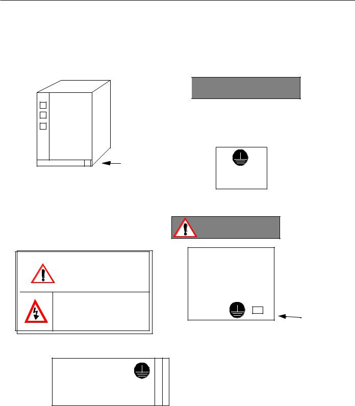
PCNC Unit

 CAUTION
WARNING LABEL
Read all Warning label’s of PCNC Unit.
BE SURE TO CONNECT GROUNDING LINE TO GROUNDING TERMINAL
|
WARNING |
|
PCNC Opeartion panel |
WARNING |
with 14” CRT Unit |
14 “CRT UNIT or |
|
|
LCD ( Expected) |
May cause electrical shock. |
rear side warning |
Do not touch inside. |
Label |
|
|
|
(Make sure to connect grounding ) |
( Make sure to connect grounding ) Read all the cautions and warnings
24 DC Power supply unit ( UPS 000004 )
xi

YASNAC PCNC Connecting Manual |
Preface/Table of Contents |
TRANSPORT PRECAUTONS

 CAUTION
•When moving the product, do not lift by the cable.
•Once the product has been installed on the machine and the eyebolts have been removed, insert suitable size machine bolts in the mounting holes.
•The product should not be exposed to harmful environmental conditions, i.e., water, harmful gases or liquids.
Failure to observe these precautions may result in personal injury or product damage.
STORAGE

 CAUTION
•This product should not be exxposed to harmful environmental conditions, i.e, water, harmful gases or liquids.
•Product should be stored in a clean indoor area that meets the following temperature and humidity conditions:
• |
Ambient temperature: -15oC to 65oC (-5oF to 149oF) |
|
• |
Relative humidity |
: 10% to 90% |
• |
Altitude |
: 1000 m or less ( 10000ft or less ) |
Failure to observe these precautions may result in personal injury or product damage.
xii

YASNAC PCNC Connecting Manual |
Preface/Table of Contents |
INSTALLATION

 CAUTION
•Install peripheral equipment in accordance with the following:
1.A rust preventative substance has been applied to the motor shaft’s end and flange. Remove the substance using a clean cloth.
2.When connecting the motor shaft to a driven machine, be sure to center-align accurately to prevent vibration.
3.Mount the servo unit(Converter,Inverter and Amplifier ) vertcally and fasten firmly in place with screws or bolts.
4.Since the servo unit (Converter,Inverter and Amplifier ) will generate heat, install the unit with sufficient clearance for cooling air flow.
5.In order to reduce heat generation, position the servo unit’s(Converter,Inverter and Amplifier) cooling fan outside of the enclosure for exposure to the external atmosphere for cooling.
6.When circulating air inside of the enclosure, do not blow air directly onto the servo unit since dust contamination could occur.
7.Position and mount components so that they are easily accessible for inspection and maintenance.
Failure to observe these precautions may result in product failure.

 CAUTION
•When installing this product, do not close the intake or exhaust ports, but take precautions to prevent foreign matter from entering this device
•Do not subject this product to any strong physical impacts.
•Set the power line capacity higher than this product’s power consumption level.
Failure to observe these precautions may result in personal injury or product damage.
xiii

YASNAC PCNC Connecting Manual |
Preface/Table of Contents |
WIRING

 CAUTION
•Use the shortest wires when making connections.This helps prevent malfunction.
•Connect the +24V DC power supply to the PC NC unit.
1.The power supply should be provided at the customer’s site. (The power supply unit, UPS000004, is available as an option.)
2. Supply the power in the range of +24V DC +10% to the PC NC unit’s inlet (CN05).
•Do not run the I/O signal wires with power wires or in the same duct. Ample separation of signal wires from power wires will reduce the noise influence.
•If noise occurs, use a noise suppressor to eliminate it. Refer to the section in this connection manual for noise filter specifications and capacities.Use of the correct noise filter will reduce noise influence.
•Be sure to complete the end-terminal-processing to the last module of the remote I/O module. Set the “TERMINATION” shorting pin to “ON”.
Failure to follow these instructions could result in malfunction.

 CAUTION
•Electrical wiring and connections should be performed by qualified personnel only.
Failure to observe this precaution could result in product failure, fire and/ or personal injury or death due to electrical shock.
•Never connect a three-phase power supply to motor output terminals, U,V or W of the drive unit. Damage to the device will occur if incorrectly connected.
•Select the type and size of wire based on your requirements and current capacity. When the ambient temperature exceeds 30oC (86oF), the allowable current drops. Select the cable size to conform to the local electrical codes and cable manufacturer’s specifications.
Failure to comply could result in an electrical fire.
•Use twisted wire or multi-core twisted pair shielded wire for general signal wires and feedback signal wires for the encoder.
These wire types help prevent malfunction.
xiv

YASNAC PCNC Connecting Manual |
Preface/Table of Contents |
|
|

 CAUTION
•The current capacity of 24V DC (external power unit for input/output contacts) is determined by the number of contact points to be used. When the current capacity is low, install an additional external power unit.
•An enclosure for this product should be designed and constructed to meet the following:
1.Use an airtight enclosure.
2.Limit the average temperature rise of air within the enclosure to less than 10oC (50oF) compared to the ambient temperature.
3.Use a UL approved fan to circuate the air in a closed enclosure to improve cooling efficiency, and to prevent abnormal heat rise.
4.Seal the cable inlet, door, etc. completely.
5.Since a CRT display attracts airborne particles due to its high voltage that could result in malfunction, therefore, provide an enclosure capable of preventing dust from entering the CPU.
6.Ambient magnetic field may cause CRT screen fluctuations, therefore, prevent this with a layout and magentism shield.
7.In PC NC Unit,printed circuit boards,various units may accumlate dust from air,may result in malfunction,therfore ,make structures to prevent the entry of dust.
8.Install packing on the cable inlet,doors,back covers,etc. to eliminate gaps or openings.
Failure to observe these precautions may result in product failure.
xv
YASNAC PCNC Connecting Manual |
Preface/Table of Contents |
|
|

 CAUTION
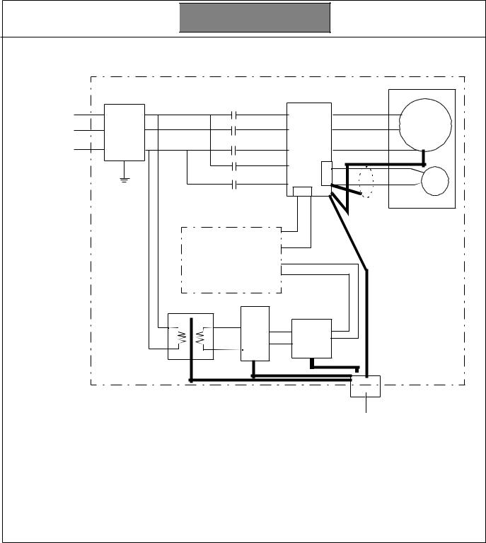
• Connect each unit’s grounding line individually to the housing or grounding plate. See the following example:
200VAC |
. |
. |
|
|
|
|
LF . |
. |
External
Box
S, V |
|
|
U |
M |
|
V |
||
|
||
W |
E |
|
CN |
||
|
||
CN |
F, B |
|
E |
|
Operation relay sequence
LF AVR
 Grounding at one point (100Ω / less)
•Select the wire for grounding in conformance with local electrical codes.
•Be sure to connect the motor’s grounding terminal to the drive unit’s grounding terminal.
• Ground at one point. (Ground resistance 100Ω or less).
•Be sure to seperate the grounding line of the unit from the power unit’s grounding line.
Failure to perform correct grounding can lead to malfunction.
xvi

YASNAC PCNC Connecting Manual |
Preface/Table of Contents |
APPLICATION SAFETY PRECAUTIONS
 CAUTION
•When operating the unit, be sure to observe the following electrical safety procedures
1.Do not touch the unit or terminal wire while the unit is operating.
2.Even though the unit has been turned OFF, it is still in charged status, so do not touch any component parts for a minimum of five minutes.
Failure to observe this precaution could result in product failure, fire and/ or personal injury or death due to electrical shock.
•Do not mishandle, pinch or cause excessive stress to cables.
Excessive load on the cable could cause electric shock.
•While the unit is turned ON, never touch any rotating parts.
Failure to observe this precaution could result in personal injury. Never modify the product
Free from explosive gases or steam
Free from oil,organic solvent,corrosive liquids etc. Vibration under (0.5 G).
Never disassmble or modify the components of the unit.
Never change the set values of the components and any variable resistors used in control panel.
Failure to observe this warning could result product failure, fire and/ or personal injury or death due to electrical shock.
xvii

YASNAC PCNC Connecting ManualChapter 1: General
1
General
Installation And Electrical Connection
This section addresses the basic system: configuration, specifications, enclosure design, electrical connections and installation.
1.1 System Configuration . . . . . . . . . . . . . . . . . . . . . . . . . . . . . . . . . . . . . . . . . . . . . . .1 - 2 1.1.1 System Configuration . . . . . . . . . . . . . . . . . . . . . . . . . . . . . . . . . . . . . . . . .1 - 2 1.1.2 Connection between Devices . . . . . . . . . . . . . . . . . . . . . . . . . . . . . . . . . . .1 - 3 1.1.3 Connector Layout NC side . . . . . . . . . . . . . . . . . . . . . . . . . . . . . . . . . . . . .1 - 4 1.1.4 Connector Layout PC side . . . . . . . . . . . . . . . . . . . . . . . . . . . . . . . . . . . . .1 - 5
1.2 General Specifications . . . . . . . . . . . . . . . . . . . . . . . . . . . . . . . . . . . . . . . . . . . . . .1 - 6
1.3 Thermal Design of Enclosure . . . . . . . . . . . . . . . . . . . . . . . . . . . . . . . . . . . . . . . . .1 - 7
1.3.1 Thermal Design. . . . . . . . . . . . . . . . . . . . . . . . . . . . . . . . . . . . . . . . . . . . . .1 - 7
1.3.2 Dust Proof Design. . . . . . . . . . . . . . . . . . . . . . . . . . . . . . . . . . . . . . . . . . . .1 - 11
1.3.3 Countermeasure Against Magnetic Fields . . . . . . . . . . . . . . . . . . . . . . . . .1 - 12
1.4 Cable Clamp and Shielding . . . . . . . . . . . . . . . . . . . . . . . . . . . . . . . . . . . . . . . . . .1 - 13
1.5 Packaging . . . . . . . . . . . . . . . . . . . . . . . . . . . . . . . . . . . . . . . . . . . . . . . . . . . . . . . .1 - 14
1.5.1 General Notes . . . . . . . . . . . . . . . . . . . . . . . . . . . . . . . . . . . . . . . . . . . . . . .1 - 14
1.5.2 Installation of PCNC Unit. . . . . . . . . . . . . . . . . . . . . . . . . . . . . . . . . . . . . .1 - 15
1.5.3 Installation of Feed/Spindle Servopacks. . . . . . . . . . . . . . . . . . . . . . . . . . .1 - 16
1 - 1
YASNAC PCNC Connecting ManualChapter 1: General
1.1System Configuration
1.1.1System Configuration
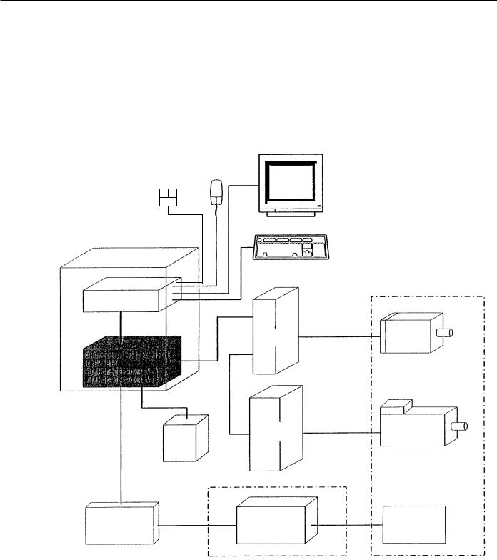
The PCNC unit of the YASNAC which is hatched in the diagram below is composed of two boards: JCP20 and JFC20 (JZNC-JFC10). It is inserted to a PC extended bus (ISA) inside PC case.
Its I/O module, servo unit, spindle drive and motor are the same as those of the YASNAC J100 CNC UNIT.
FDD Mouse
Monitor with Touch screen
PC NC case
Keyboard
Machine
PC
ISA bus
Feeding |
Feeding |
servo unit |
motor |
JFC10
DC |
Spindle |
Spindle motor |
|
drive unit |
|||
|
|||
+24V |
|
|
|
power |
|
|
Device I/O Module High voltage on
machine side
Figure 1.1.1 YASNAC PCNC System Structure Diagram
1 - 2

YASNAC PCNC Connecting ManualChapter 1: General
1.1.2Connection Between Devices
C P U R A C K U N IT |
|
|
|
|
|
|
|
|
|
|
|
|
|
C R T |
|
|
|
|
|
|
|
|
|
|
K E YB O AR D |
|
|
|
|
|
H D D |
D A TA |
|
|
|
|
|
|
|
A T X |
P W R |
|
|
M O U SE |
|
|
|
||
|
|
|
|
|
|
||||
|
|
|
|
|
|
|
|
||
M O T H E R |
|
|
|
|
|
|
T B 3 |
|
|
B O A R D |
|
|
|
D A TA F D D |
|
|
|
||
|
|
|
P W R |
|
|
|
|||
ID E I/F |
|
|
|
|
|
|
|
|
|
K B D |
|
|
|
|
T S |
|
|
|
|
C O M 2 |
|
|
|
|
C O N T R O L |
|
|
|
|
F D D |
|
|
|
|
|
|
T O U C H |
|
|
|
|
|
|
|
|
SC R EE N |
|
||
|
|
|
|
S E R V O O N |
|
||||
C O M 1 |
|
|
|
|
|
|
|||
|
|
|
|
|
|
|
|
|
|
P S /2 M O U S E |
|
|
|
S H U T D O W N |
|
|
|
||
|
|
|
|
|
|
|
|
|
|
LP T 1 |
|
|
D C |
|
|
|
|
|
|
|
|
|
|
|
|
|
|
|
|
|
|
|
O U T |
|
|
|
|
|
|
VID E O |
|
2 4V D C FO R |
M A C H IN E |
|
|
|
|
||
|
M A C H IN E I/O |
M A C H IN E O P . PA N EL I/O |
|||||||
C A R D |
|
|
C O N T R O L |
||||||
|
|
S IG N A LS |
|
|
|
|
|||
|
|
|
|
|
|
|
|
||
P C I |
|
V ID E O |
C N 1 ~6 |
|
C N 14 |
C N 5 |
|
|
|
|
|
I/O B O A R D |
I/O B O A R D |
C N 1 |
H P G |
||||
|
|
|
FO R M A C H IN E S IG N A L |
|
|||||
|
|
|
|
F O R M A C H IN E |
|
||||
|
|
|
(FC 8X X ) |
|
|
|
|||
|
|
|
|
|
O P . P N L . |
|
|
||
|
|
|
C N 1 1 |
|
|
|
|
|
|
|
|
|
|
|
|
(JS P 0 2 /0 4) |
|
|
|
|
|
|
|
|
|
|
|
|
|
|
|
|
C N 1 3 |
|
C N 12 |
C N 3 |
C N 7,8,9 |
|
|
|
|
|
|
|
|
|
|||
JF C 20 |
C N 01 |
|
|
|
|
|
M A C H IN E P A N E L |
||
|
|
S E N S O R S IG N A L |
|
|
|||||
|
|
C N 02 |
|
|
|
S IG N A LS |
|||
|
|
|
|
|
|
|
|
|
|
|
|
C N 03 |
|
|
S ER V O U N IT |
|
SG M G - |
||
|
|
C N 04 |
|
S G D C -**A J A |
|
**A 2A B * |
|||
|
|
|
|
M |
|
||||
IS A |
|
C N 05 |
|
4C N |
|
3C N |
|
|
|
|
|
|
1C N |
|
|
|
|
|
|
|
|
|
|
Z AX IS |
|
|
|
||
|
|
|
|
5 2C N |
|
|
|
||
|
|
|
|
|
2C N |
|
P G |
|
|
|
|
|
|
5 1C N |
|
|
|
||
|
|
|
|
|
|
|
|
|
|
|
|
|
|
S G D C -**AJA |
|
M |
|
||
|
|
|
|
4C N |
|
3C N |
|
|
|
FA N 1 |
|
|
|
1C N |
|
|
|
|
|
JC P 20 -1 |
C N 11 |
|
Y A XIS |
|
|
|
|||
|
|
|
5 2C N |
|
|
|
|||
|
|
C N 12 |
|
|
2C N |
|
P G |
|
|
|
|
|
5 1C N |
|
|
|
|||
|
|
C N 13 |
|
|
|
|
|
|
|
|
|
|
|
|
|
|
|
|
|
C P U |
|
C N 14 |
|
S G D C -**AJA |
|
|
|
||
FA N |
|
|
|
M |
|
||||
|
|
|
|
4C N |
|
3C N |
|
|
|
|
|
|
|
1C N |
X A XIS |
|
|
|
|
|
|
|
|
5 2C N |
|
|
|
||
|
|
|
|
|
2C N |
|
P G |
|
|
|
|
|
|
5 1C N |
|
|
|
||
|
|
|
|
|
|
|
|
|
|
FA N 3 |
C A S E FA N |
|
IN VE R TE R U N IT |
U AA SK *-**F Z * |
|||||
|
|
|
|
|
C 1M R -M 5N |
|
|
F A |
|
|
|
|
|
4C N |
|
|
|
M |
|
|
|
|
|
|
|
|
N |
||
|
PC P O W E R |
|
|
|
|
|
|
||
|
|
1C N |
|
|
|
|
|
||
|
SU P PL Y |
|
|
|
|
|
|
|
|
O U T |
O U T |
|
5 2C N |
|
|
|
|
|
|
|
|
P G S |
|
|
2C N |
|
P G |
|
|
|
IN P U T |
(P O W E R |
|
5 1C N |
|
|
|
||
|
|
G O O D |
|
|
|
|
|
|
|
|
|
S IG N A L ) |
|
|
|
|
|
|
|
|
|
|
C O N V ER T ER U N IT |
|
|
|
|||
|
|
|
|
C 1 M R -M R 5N |
|
|
|
||
|
|
|
|
|
|
|
R E A C T O R |
|
|
|
|
N C PO W E R |
5C N |
|
|
R /S /T |
X0 10 0 ** |
|
|
|
|
|
|
|
|
|
|||
|
|
S U PP L Y |
|
|
|
|
|
|
|
IN P U T |
O U TP U T |
A 1 /A 2 |
|
|
IN P U T PO W E R U N IT |
|
|
TB 2 |
S V M |
|
TB 1 |
|
|
N FB |
|
AC 2 30 V |
S V M |
A 1/A 2 |
Figure 1.1.2.1 Detail Connection of PCNC Unit with various devices.
1 - 3
YASNAC PCNC Connecting ManualChapter 1: General
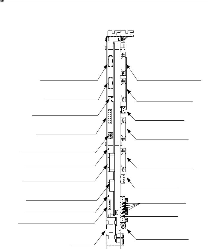
1.1.3Connector Layout NC Side
The following figure gives the detail Connectors Layout of YASNAC JZNC-JFC10 board.
Servo controller connector (CN01)
I/O module connector (CN02)
Power good signal connector (CN03)
Interruption setting short pin (S11)
Memory address setting rotary switch (S12)
I/O module power output verification LED
I/O module power output connector (CN04)
I/O module power input connector (CN05)
I/O module power input verification LED
Battery power reply supply connector (CN06)
Battery
Servo controller I/O connector (CN11)
Power On/Off connector (CN12)
Fuse (HM03, 0.3A) (F1)
RS232C connector (CN14)
Direct IN/OUT connector (CN14)
System load switch (S1)
System load switch (S1)
(from top: 1, 2, 3, 4) Battery alarm LED
System load rotary switch (S1)
FIGURE 1.1.3.1: Details Layout of YASNAC JZNC-JFC10 Board
1 - 4
YASNAC PCNC Connecting ManualChapter 1: General
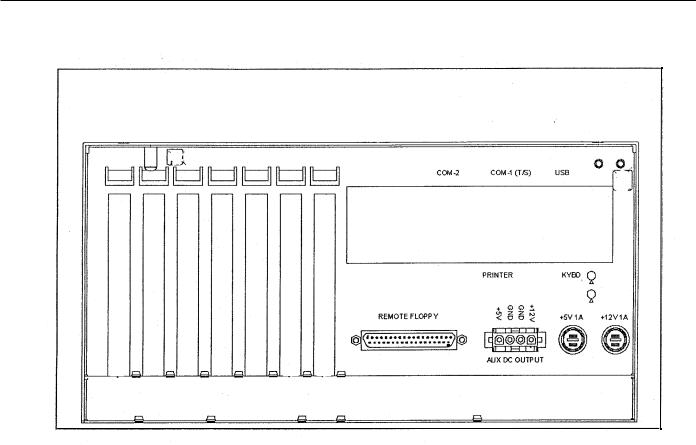
1.1.4Connector Layout PC Side
FIGURE 1.1.4.1: Connector Layout on the top view of the PCNC CPU rack
1 - 5

YASNAC PCNC Connecting ManualChapter 1: General
1.2 General Specifications
The enclosure should be designed to meet all of the following conditions.
|
|
Table 1.2.1: Specifications |
|
||
|
|
|
|
|
|
Item |
|
|
Specifications |
|
|
|
|
|
|
|
|
|
|
|
|
|
|
|
|
|
Storage and |
-15oC to +65oC |
|
|
|
|
Transportation |
|
|
|
|
|
|
|
|
|
|
|
|
|
|
|
|
|
|
PCNC unit |
|
|
Temperature* |
|
Operating |
I/O module |
0oC to +53oC |
|
|
|
Servopack |
||
|
|
|
(around |
||
|
|
|
14” Color monitor with |
|
|
|
|
|
enclosure) |
|
|
|
|
|
touch screen |
|
|
|
|
|
|
|
|
|
|
|
|
|
|
|
Humidity |
20% to 80% RH (with operation) |
|||
Ambient Conditions |
|
|
10% to 90% RH (with non-operation) |
||
|
|
|
|
||
|
Vibration |
Less than 4.9m/s |
|
||
|
during operation |
|
|||
|
|
|
|||
|
|
|
|||
|
Others |
Free from dust, coolant or organic solvent |
|||
|
|
|
|
|
|
|
PCNC Unit input power supply |
+24VDC+10% |
|
||
|
180V-264V AC |
|
|||
|
|
|
|
|
|
• Input power supply voltage: 180V-264VAC Power Supply Unit UPS000004 • Frequency: 47 Hz to 63 Hz
• Momentary interruption: 0.5 cycle (0 VDC)
Note: Avoid installing the control panel in a location subject to direct sunlight, near heat generating devices or outdoors even if the ambient temperature is within the specified range.
1 - 6
YASNAC PCNC Connecting ManualChapter 1: General
1.3Thermal Design of Enclosure
1.3.1Thermal Design
Design of the enclosure should be made on the basis that the average temperature increase of air within the enclosure (containing the PC NC unit and other components) should be 10oC below the external air temperature.
(1) Temperature Increase within the Enclosure (Average Temperature Increase) The internal temperature increase (sheet metal enclosure) is generally as follows:
∆Τ= |
P |
|
= |
P |
|
|
qe |
k.A |
|||||
|
|
|||||
where, |
|
|
|
|
|
|
∆Τ : Internal temperature increase (oC)
P : Heat generation in enclosure (W)
qe : Enclosure heat percolation ratio (W/oC)
k: Heat transit ratio of sheetmetal (W/m2oC) 6W/m2oC: With internal cooling fan
4W/m2oC: Without internal cooling fan
A : Efficient heat diffusion area of enclosure (m2)
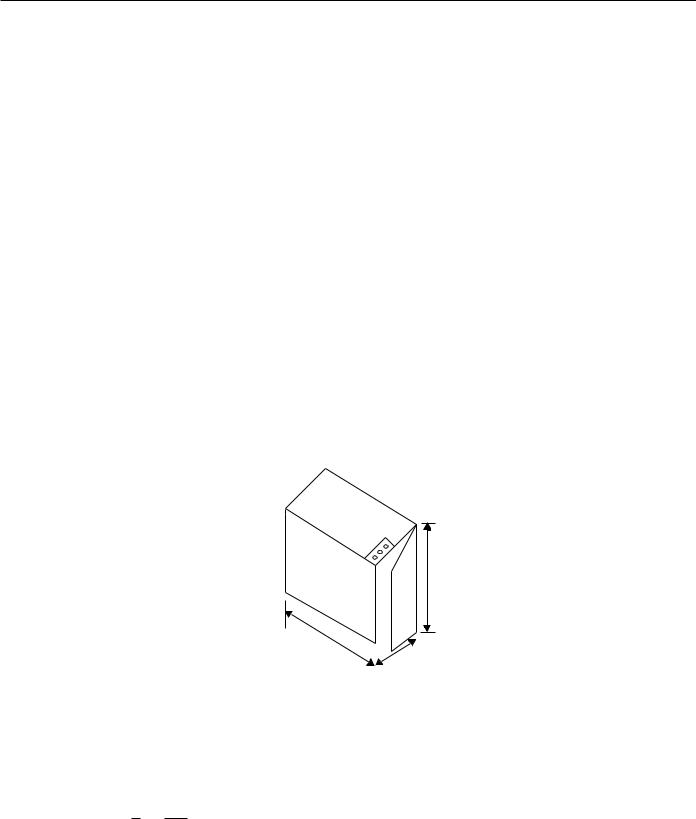
1200
All dimensions in millimeters |
|
Fig 1.5 Dimensions of Enclosure |
|
|
|||
800 |
700 |
||
|
|||
|
|
Efficient heat diffusion area is independently located, so bottom area is excluded.
A=4.16m2.
If the heat generation in the enclosure is supposed to be 246W (113 W in CNC
portion, 104 W in servo portion, and 29 W in I/o portion),
∆Τ= |
P |
P |
|
||
qe = |
k.A |
|
|
||
|
246 |
|
o |
||
= |
|
|
|
= 9.9 ( C) |
|
6 x 4.16 |
|||||
1 - 7
YASNAC PCNC Connecting ManualChapter 1: General
(2)Heat Exchanger Cooling Capacity
Where cooling capacity is insufficient even with a circulating fan mounted in the enclosure, Yaskawa can provide heat exchangers.
Table 1.3.1.1: Heat Exchangers
Heat Exchanger |
Cooling Capacity |
External Dimensions (mm) |
|
|
|
|
|
|
REX1550 |
100W /10oC |
295 width x 890 height x 50 depth |
|
|
|
HEATEX02 |
250W /10oC |
440 width x 924 height x 50 depth |
|
|
|
The heat generation indicated in the above table is the allowable heat generated when the internal temperature increase in the enclosure is limited to under 10oC.
Example: Allowable Heat Generated in the Enclosure with Heat Exchanger
The amount of internal heat generated to make the internal temperature under 10oC when the enclosure is equipped with a HEATEX02 Heat Exchanger is expressed by the following equation:
.....................................................
P= k.A.∆Τ+ 250 W/10 oC
=6 x 4.16 x 10 + 250
=499 W/10 oC
therefore, it is necessary to be under 499W.
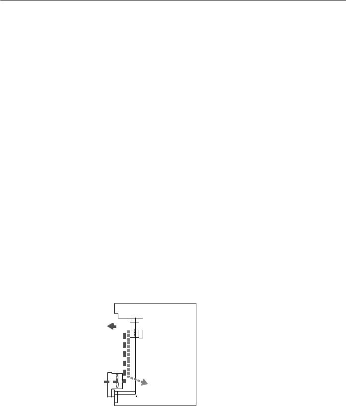
(3)Mounting Heat Exchanger
Heat exchanger should be mounted on the enclosure provided by the machine tool builder. Fig. 1.5 shows a mounting example. Mount the exchanger so that the internal air is drawn from the upper portion and discharged through the lower portion, while external air is drawn in from the lower portion and discharged through the upper portion.


 Internal air
Enclosure
External air 

 Heat exchanger
Fig 1.3.1.1: Mounting of Heat Exchanger on the enclosure made by Machine builder
1 - 8

YASNAC PCNC Connecting ManualChapter 1: General
(4)Heat Generation by Respective Units
Unit |
Type |
Total Heat |
Internal |
Minimum |
|
|
|
|
Generation |
Heat |
Wind |
|
|
|
(W) |
Generation |
Velocity for |
|
|
|
|
(W) |
Cooling |
|
|
|
|
|
|
|
|
|
|
|
|
PCNC rack |
JZNC-JPCRKM_-_ |
|
|
|
|
|
|
|
|
|
|
14” Color CRT with |
JZNC-JPCOP-_ _ _ |
|
|
|
|
Touchscreen |
|
|
|
||
|
|
|
|
||
|
|
|
|
|
|
|
|
JANCD-FC810* |
29 |
29 |
0 |
|
|
|
|
|
|
I/O Module |
JANCD-FC860* |
29 |
29 |
0 |
|
|
|
|
|
|
|
|
|
JANCD-FC861* |
14.5 |
14.5 |
0 |
|
|
|
|
|
|
|
|
CIMR-MR5N23P7 |
84 |
44 |
|
|
|
|
|
|
|
|
|
CIMR-MR5N25P5 |
84 |
44 |
|
|
|
|
|
|
|
|
|
CIMR-MR5N27P5 |
119 |
61 |
|
|
|
|
|
|
|
Converter |
|
CIMR-MR5N2011 |
152 |
70 |
2.5 |
|
|
|
|
||
|
CIMR-MR5N2015 |
204 |
88 |
||
|
|
|
|||
|
|
|
|
|
|
|
|
CIMR-MR5N2018 |
273 |
108 |
|
|
|
|
|
|
|
|
|
CIMR-MR5N2022 |
335 |
132 |
|
|
|
|
|
|
|
|
|
CIMR-MR5N2030 |
392 |
160 |
|
|
|
|
|
|
|
|
|
CIMR-MR5N23P7 |
84 |
44 |
|
|
|
|
|
|
|
|
|
CIMR-MR5N25P5 |
185 |
58 |
|
|
|
|
|
|
|
|
|
CIMR-MR5N27P5 |
244 |
77 |
|
|
|
|
|
|
|
Spindle Inverter |
|
CIMR-MR5N2011 |
307 |
89 |
2.5 |
|
|
|
|
||
|
CIMR-MR5N2015 |
454 |
119 |
||
|
|
|
|||
|
|
|
|
|
|
|
|
CIMR-MR5N2018 |
565 |
144 |
|
|
|
|
|
|
|
|
|
CIMR-MR5N2022 |
717 |
180 |
|
|
|
|
|
|
|
|
|
CIMR-MR5N2030 |
869 |
219 |
|
|
|
|
|
|
|
|
|
UZBA-B 20A 0.53 mH |
35 |
35 |
0 |
|
|
|
|
|
|
|
|
UZBA-B 30A 0.35 mH |
45 |
45 |
0 |
|
|
|
|
|
|
|
|
UZBA-B 40A 0.265 mH |
50 |
50 |
0 |
|
|
|
|
|
|
Reactor |
|
UZBA-B 60A 0.18 mH |
65 |
65 |
0 |
|
|
|
|
|
|
|
UZBA-B 80A 0.13 mH |
75 |
75 |
0 |
|
|
|
||||
|
|
|
|
|
|
|
|
UZBA-B 90A 0.12 mH |
90 |
90 |
0 |
|
|
|
|
|
|
|
|
UZBA-B 120A 0.09 mH |
90 |
90 |
0 |
|
|
|
|
|
|
|
|
UZBA-B 160A 0.07 mH |
100 |
100 |
0 |
|
|
|
|
|
|
1 - 9

YASNAC PCNC Connecting ManualChapter 1: General
Unit |
Type |
Total Heat |
Internal |
Minimum |
|
|
|
|
Generation |
Heat |
Wind |
|
|
|
(W) |
Generation |
Velocity for |
|
|
|
|
(W) |
Cooling |
|
|
|
|
|
|
|
|
|
|
|
|
|
|
SGDC-05AJ A |
28 |
10 |
|
|
|
|
|
|
|
|
|
SGDC-10AJ A |
48 |
12 |
|
|
|
|
|
|
|
Servo Unit |
|
SGDC-15AJ A |
73 |
15 |
2.5 |
|
|
|
|
||
|
SGDC-20AJ A |
108 |
18 |
||
|
|
|
|||
|
|
|
|
|
|
|
|
SGDC-30AJ A |
148 |
22 |
|
|
|
|
|
|
|
|
|
SGDC-50AJ A |
208 |
28 |
|
|
|
|
|
|
|
|
1. The heat generated by the CNC unit varies depending on the addition |
|
POINT |
of options. The heat generated by the I/O module varies with I/O |
|
status. |
||
|
2.Internal heat generation is the heat remaining inside of the enclosure when the servo unit’s fin is exposed outside of the enclosure, and when the external air is applied to the fin at greater than 2.5m/s
3.Thermal design of the enclosure to house the servo unit varies with machine specifications, but is acknowledged to use a value of 70% of the load factor.
1 - 10
YASNAC PCNC Connecting ManualChapter 1: General
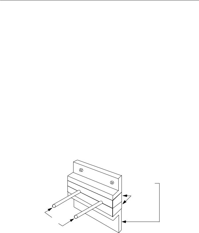
1.3.2Dust proof Design
Dust proof Design and Construction
PCNC units and other components (especially CRTs) housed in a machine tool enclosure are exposed to an environment with airborne matter, e.g., dust. oil, coolant mist, etc.Since these elements could cause control component malfunction, enclosures should be designed and built to prevent such matter from entering as follows:
•Use an air-tight enclosure.
•Seal the cabinet inlet with packing material. Refer to Fig. 1.3.2.1.
•Secure the rear door lid with packing material. Refer to Fig, 1.3.2.2.
•The enclosure’s front surfaces with PCNC operating panels and are dust proof, but do not install them where liquid coolants are present. The periphery should be sealed with suitable materials.
The CRT unit’s high voltage will attract airborne dust, so when mounting the CRT unit’s pendant box please take note of the following:
1.Seal the cable inlet, door, rear lid opening clearances with packing material.
2.The CRT Unit’s mounting surface has been factory sealed.
3.Seal any other openings.
4.Since oil will enter the enclosure through screw holes and collect on the internal ceiling surface, apply suitable packing material to seal these holes.
 Metal fitting
Packing
Cable
Fig. 1.3.2.1 Cable Inlet
1 - 11
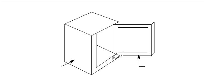
YASNAC PCNC Connecting ManualChapter 1: General
Pendant box |
Packing |
Fig. 1.3.2.2 Door Packing
1.3.3Countermeasures against Magnetic Fields
The CRT screen’s display may fluctuate due to ambient magnetic fields. To prevent this, keep magnetic generating materials, e.g., transformers, reactors, fans, electro-magnetic switches, solenoid relays, exchange power cables, etc. a minimum of 300mm from the CRT.
The value of 300mm is a general standard and could vary depending on the situation, therefore, be aware of the presence of magnetic generating sources when positioning the CRT unit.
1 - 12
Loading...