


 Loading...
VS-616G5
Option Instruction Manual
Profibus-DP Control Card SI-P

! WARNING
PRECAUTIONS
1.Read this instruction manual in its entirety before installing the Profibus-DP Control Card SI-P or operating the inverter with this card installed.
2.DO NOT connect or disconnect wiring, or perform signal checks while the electrical power is turned ON.
Failure to observe these and other precautions indicated in this manual will expose the user to high voltages, resulting in serious injury or death. Damage to equipment may also occur.
! CAUTION
NOTE
The Option Card uses CMOS IC chips. Therefore, the card could become damaged when physically handled if static electricity is present. The person handling the card should wear a discharge strap to eliminate the possibility of static charge (if present) affecting the card.
Failure to observe this precaution may result in equipment damage.
NOTICE
Printed March, 1998. The information contained within this document is the proprietary property of Yaskawa Electric America, Inc., and may not be copied, reproduced or transmitted to other parties without the expressed written authorization of Yaskawa Electric America, Inc.
No patent liability is assumed with respect to the uses of the information contained herein. Moreover, because Yaskawa is constantly improving its high quality product, the information contained in this manual is subject to change without notice. Every precaution has been taken in the preparation of this document. Nevertheless, Yaskawa assumes no responsibility for errors or omissions. Neither is any liability assumed for damages resulting from the use of the information contained in this publication.
Page 2 |
VS-616G5 Option Instruction Manual: Profibus-DP Control Card SI-P |

INTRODUCTION
The Profibus-DP Control Card SI-P is used to connect the VS-616G5 inverter to a Profibus-DP network. The option card supports 32 bytes of input data, 32 bytes of output data, data transmission rates of up to 12 Mbps, and uses a RS-485 electrical interface.
Description of the Profibus-DP Option Card (SI-P) for the VS-616G5
Name |
YEA Code Number |
Functions |
|
|
|
|
|
Profibus-DP |
|
• Connects inverter to and communicates with a Profibus-DP communication network. |
|
|
• Option card plugs into 2CN connector on the control board. |
||
Option Card |
YAG5-PDP |
||
• Option card supports 32 bytes of input data and 32 bytes of output data. |
|||
SI-P |
|
||
|
• The card requires VS-616G5 Flash # VSG101042 or higher. |
||
|
|
||
|
|
|
60-pin Connector to |
Indication LED’s |
inverter control board (2CN) |
Terminal Block TC1 

Termination Switch 

Address Switch 1 (× 10)
Address Switch 2 (× 1)
Grounding lead wire |
YAG5-PDP-T20095 |
|
(connect to terminal #12 |
||
|
||
of inverter control board) |
|
 Stand-off mounting hole (4.0mm) dia.
 Stand-off mounting hole (4.0mm) dia.
SI-P
CODE NO. 73600-C0220
Fig. 1 Profibus-DP Control Card SI-P
VS-616G5 Option Instruction Manual: Profibus-DP Control Card SI-P |
Page 3 |

INSTALLATION
1.Before attempting to install or use the Profibus-DP Control Card SI-P, please read these instructions.
2.After unpacking the card, verify that the code number is correct and that no damage has occurred during shipping. Contact your YASKAWA representative if you should require any assistance.
3.Turn OFF the main electrical power to the inverter.
4.Remove the inverter’s digital operator. Then remove the inverter’s front cover. Refer to the VS616G5 User’s Manual for specific removal instructions for your particular inverter size.
5.Check that the indicator CHARGE lamp is OFF (power OFF indication).
6.Plug the 2CN connector of Profibus-DP Control Card SI-P into the 2CN connector (60 pins) on
the control board of the inverter. Gently push the SI-P card until the stand-off posts engage the two holes on the option card. Secure the SI-P card (See part of the side view).
7.Attach the green PE (Protected Earth) cable to terminal 12 of the VS-616G5 control board. The SHIELD is connected to pin 5 in the BUS connector.
A
8. Replace the inverter’s cover. Refer to Fig. 4 for correct wiring of the Profibus-DP Control Card and the Control Board.
Option A |
|
Top |
Mounting base |
4CN Option A connector |
7CN |
|
of inverter |
|
|
|
|
|
|
|
A |
2CN Option C connector |
|
|
Option C |
|
|
|
SI-P |
|
|
|
Control card |
3CN Option D connector |
|
|
Option D |
|
|
|
|
Connector terminal |
|
|
|
Grounding terminal 12 |
|
Bottom |
|
|
|
|
|
|
Front View |
|
Side View |
Fig. 2 Installation of the Profibus-DP Control Card SI-P
Page 4 |
VS-616G5 Option Instruction Manual: Profibus-DP Control Card SI-P |
! CAUTION
WIRING NOTES
1.Separate the control signal wires (from terminal block TC1 on the option card) from the main circuit wires and other power cables.
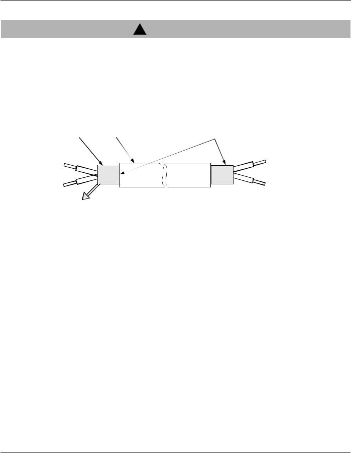
2.Use twisted shielded wire to connect the communication signals. Prepare the wire as shown in Fig. 3 to prevent noise interference.
Shield Sheath |
|
Armor |
B |
A |
C
Fig. 3 Shielded Wire
A.NEVER connect the wire’s shield to ground.
B.WRAP insulating tape around shielded areas and wires where termination occurs.
.
C. CONNECT the shielded wire end to the Grounding Terminal (E) on the inverter’s Terminal E (G).
3. Care must be taken in the selection of the twisted shielded wire in lengths over 50 ft. The impedance of the wire should be low enough to insure sufficient signal amplitude for proper operation of all communication equipment connected to the SI-P card. In general, as the length of wire is increased, the cross section or gauge must also increase.
4. Please observe National Electrical Code (NEC) and any other governing regional or local code when wiring electrical devices.
Wiring Connection Notes:
1.To prevent noise, use shielded wire as specified in Fig. 3. Separate from the power circuits (100VAC or greater).
2.Terminate shielded wire correctly (Refer to Fig. 3).
3.Applicable wire sizes for terminal block TC1 is listed in Table 1.
VS-616G5 Option Instruction Manual: Profibus-DP Control Card SI-P |
Page 5 |

Table 1: Applicable Wire Sizes for Terminal Block TC1
Wire / Installation Type |
Cross-sectional Area [mm2] |
AWG |
I [A] |
VAC [V] |
Thin twisted wire |
1 |
16 |
12 |
125 |
|
|
|
|
|
Solid Wire |
1.5 |
16 |
12 |
125 |
|
|
|
|
|
UL |
— |
22-16 |
10 |
300 |
|
|
|
|
|
CSA |
— |
26-16 |
10 |
300 |
|
|
|
|
|
CSA |
— |
26-16 |
10 |
150 |
|
|
|
|
|
Wiring Terminal Block TC1
The Profibus organization only specifies the pin layout of a 9-pin D-SUB for the terminal block. The terminal block on the option card follows the pin layout of the connector on the SI-P option card which has been tested and approved by the Profibus organization.
Table 2: External Function Terminals of the SI-P Option Card
Pin # |
Name |
Function |
|
|
|
1 |
+5V BUS |
Isolated +5V from RS 485 side * |
|
|
|
2 |
GND BUS |
Isolated GND from RS 485 side * |
|
|
|
3 |
A-Line |
Positive RxD/TxD according RS 485 specification |
|
|
|
4 |
B-Line |
Negative RxD/TxD according RS 485 specification |
|
|
|
5 |
Shield |
BUS cable shield. Connected to PE internally on the option card |
|
|
|
6 |
RTS |
Request To Send * |
|
|
|
* Optional pins. Not used in a standard RS 485 Profibus-DP installation.
Page 6 |
VS-616G5 Option Instruction Manual: Profibus-DP Control Card SI-P |
Loading...