


 Loading...
OWNER’S MANUAL
YZF-R1
5PW-28199-E0
EAU03338 |
INTRODUCTION |
|
|
|
|
|
|
Welcome to the Yamaha world of motorcycling!
As the owner of a YZF-R1, you are benefiting from Yamaha’s vast experience and newest technology regarding the design and manufacture of high-quality products, which have earned Yamaha a reputation for dependability.
Please take the time to read this manual thoroughly, so as to enjoy all advantages of your YZF-R1. The owner’s manual does not only instruct you in how to operate, inspect and maintain your motorcycle, but also in how to safeguard yourself and others from trouble and injury.
In addition, the many tips given in this manual will help keep your motorcycle in the best possible condition. If you have any further questions, do not hesitate to contact your Yamaha dealer.
The Yamaha team wishes you many safe and pleasant rides. So, remember to put safety first!
IMPORTANT MANUAL INFORMATION |
EAU00005 |
|
Particularly important information is distinguished in this manual by the following notations:
The Safety Alert Symbol means ATTENTION! BECOME ALERT! YOUR SAFETY IS
INVOLVED!
WARNING |
Failure to follow WARNING instructions could result in severe injury or death to the |
|
motorcycle operator, a bystander, or a person inspecting or repairing the |
||
|
||
|
motorcycle. |
|
CAUTION: |
A CAUTION indicates special precautions that must be taken to avoid damage to the |
|
motorcycle. |
||
|
NOTE: A NOTE provides key information to make procedures easier or clearer.
NOTE:
●This manual should be considered a permanent part of this motorcycle and should remain with it even if the motorcycle is subsequently sold.
●Yamaha continually seeks advancements in product design and quality. Therefore, while this manual contains the most current product information available at the time of printing, there may be minor discrepancies between your motorcycle and this manual. If you have any questions concerning this manual, please consult your Yamaha dealer.
IMPORTANT MANUAL INFORMATION
EW000002
 WARNING
PLEASE READ THIS MANUAL CAREFULLY AND COMPLETELY BEFORE OPERATING THIS MOTORCYCLE.

IMPORTANT MANUAL INFORMATION
EAU04229
YZF-R1
OWNER’S MANUAL ©2001 by Yamaha Motor Co., Ltd.
1st edition, November 2001 All rights reserved.
Any reprinting or unauthorized use without the written permission of Yamaha Motor Co., Ltd.
is expressly prohibited. Printed in Japan.

EAU00009 |
TABLE OF CONTENTS |
|
|
|
|
|
|
1 |
GIVE SAFETY THE RIGHT OF WAY |
|
1 |
|
|
|
|
|
|
|
|
2 |
DESCRIPTION |
|
2 |
|
|
|
|
|
|
|
|
3 |
INSTRUMENT AND CONTROL FUNCTIONS |
|
3 |
|
|
|
|
|
|
|
|
4 |
PRE-OPERATION CHECKS |
|
4 |
|
|
|
|
|
|
|
|
5 |
OPERATION AND IMPORTANT RIDING POINTS |
|
5 |
|
|
|
|
|
|
|
|
6 |
PERIODIC MAINTENANCE AND MINOR REPAIR |
|
6 |
|
|
|
|
|
|
|
|
7 |
MOTORCYCLE CARE AND STORAGE |
|
7 |
|
|
|
|
|
|
|
|
8 |
SPECIFICATIONS |
|
8 |
|
|
|
|
|
|
|
|
9 |
CONSUMER INFORMATION |
|
9 |
|
|
|
|
INDEX


 GIVE SAFETY THE RIGHT OF WAY
GIVE SAFETY THE RIGHT OF WAY ................................................ |
1-1 |
1

GIVE SAFETY THE RIGHT OF WAY |
EAU00021 |
|
Motorcycles are fascinating vehicles, which can give you an unsurpassed feeling of power and freedom. However, they also impose certain limits, which you must accept; even the best motorcycle does not ignore the laws of physics.
1
Regular care and maintenance are essential for preserving value and operating condition of your motorcycle. Moreover, what is true for the motorcycle is also true for the rider: good performance depends on being in good shape. Riding under the influence of medication, drugs and alcohol is, of course, out of the question. Motorcycle riders—more than car drivers—must always be at their mental and physical best. Under the influence of even small amounts of alcohol, there is a tendency to take dangerous risks.
Protective clothing is as essential for the motorcycle rider as seat belts are for car drivers and passengers. Always wear a complete motorcycle suit (whether made of leather or tear-resistant synthetic materials with protectors), sturdy boots, motorcycle gloves and a properly fitting helmet. Optimum protective wear, however, should not encourage carelessness. Although full-coverage helmets and suits, in particular, create an illusion of total safety and protection, motorcyclists will always be vulnerable. Riders who lack critical self-control run the risk of going too fast and are apt to take chances. This is even more dangerous in wet weather. The good motorcyclist rides safely, predictably and defensively—avoiding all dangers, including those caused by others.
Enjoy your ride!
1-1
|
DESCRIPTION |
|
|
Left view ............................................................................................. |
2-1 |
Right view........................................................................................... |
2-2 |
Controls and instruments ................................................................... |
2-3 |
2

DESCRIPTION |
EAU00026 |
|
Left view
2
1. Fuse box |
(page 6-35) |
2. Front fork compression damping force adjusting screw |
(page 3-20) |
3. Front fork rebound damping force adjusting screw |
(page 3-20) |
4. Front fork spring preload adjusting bolt |
(page 3-19) |
5. Front brake fluid reservoir |
(page 6-26) |
6. Throttle stop screw |
(page 6-18) |
7. Shock absorber assembly spring preload adjusting ring |
(page 3-21) |
8. Shock absorber assembly compression damping force adjusting screw |
(page 3-22) |
9. Owner’s tool kit |
(page 6-1) |
10. Shock absorber assembly rebound damping force adjusting screw |
(page 3-22) |
11. Engine oil drain bolt |
(page 6-10) |
12. Engine oil filter cartridge |
(page 6-10) |
2-1

DESCRIPTION
Right view
2
13. Luggage strap holders |
(page 3-23) |
19. Air filter element |
(page 6-16) |
14. Helmet holders |
(page 3-18) |
20. Radiator cap |
(page 6-13) |
15. Main fuse |
(page 6-35) |
21. Coolant reservoir |
(page 6-12) |
16. Electronic fuel injection fuse |
(page 6-35) |
22. Engine oil level check window |
(page 6-9) |
17. Battery |
(page 6-33) |
23. Engine oil filler cap |
(page 6-9) |
18. Rear brake fluid reservoir |
(page 6-26) |
|
|
2-2
DESCRIPTION
Controls and instruments
2
1. Clutch lever |
(page 3-13) |
5. Tachometer |
(page 3-11) |
2. Left handlebar switches |
(page 3-11) |
6. Right handlebar switches |
(page 3-12) |
3. Multi-function display |
(page 3-6) |
7. Throttle grip |
(page 6-19) |
4. Main switch/steering lock |
(page 3-1) |
8. Brake lever |
(page 3-13) |
2-3

INSTRUMENT AND CONTROL FUNCTIONS
Main switch/steering lock ..................................... |
3-1 |
Indicator and warning lights ................................ |
3-2 |
Multi-function display ........................................... |
3-6 |
Tachometer ........................................................ |
3-11 |
Anti-theft alarm (optional) .................................. |
3-11 |
Handlebar switches ........................................... |
3-11 |
Clutch lever ........................................................ |
3-13 |
Shift pedal .......................................................... |
3-13 |
Brake lever ......................................................... |
3-13 |
Brake pedal ........................................................ |
3-14 |
Fuel tank cap ..................................................... |
3-14 |
Fuel .................................................................... |
3-15 |
Fuel tank breather hose .................................... |
3-16 |
|
|
Catalytic converter ............................................ |
3-16 |
|
|
Seats ................................................................. |
3-17 |
|
|
Helmet holders .................................................. |
3-18 |
|
|
Storage compartment ....................................... |
3-19 |
|
|
Adjusting the front fork |
3-19 |
|
|
3 |
|||
Adjusting the shock absorber assembly |
3-21 |
||
|
|||
......................................Luggage strap holders |
3-23 |
|
|
EXUP system .................................................... |
3-24 |
|
|
Sidestand .......................................................... |
3-24 |
|
|
Ignition circuit cut-off system ............................. |
3-25 |
|

INSTRUMENT AND CONTROL FUNCTIONS |
EAU00027 |
|
3
1. Push.
2. Turn.
EAU00029 |
EAU00040 |
Main switch/steering lock
The main switch/steering lock controls the ignition and lighting systems, and is used to lock the steering. The various positions are described below.
EAU00036
ON
All electrical systems are supplied with power, and the engine can be started. The key cannot be removed.
EAU00038
LOCK
The steering is locked, and all electrical systems are off. The key can be removed.
To lock the steering
1.Turn the handlebars all the way to the left.
2.Push the key in from the “OFF” position, and then turn it to “LOCK” while still pushing it.
3.Remove the key.
EW000016
 WARNING
_
Never turn the key to “OFF” or “LOCK” while the motorcycle is moving, otherwise the electrical systems will be switched off, which may result in loss of control or an accident. Make sure that the motorcycle is stopped before turning the key to “OFF” or “LOCK”.
_
OFF
All electrical systems are off. The key can be removed.
To unlock the steering
Push the key in, and then turn it to “OFF” while still pushing it.
3-1
INSTRUMENT AND CONTROL FUNCTIONS
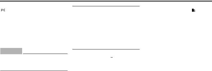
EAU04492
(Parking)
The steering is locked, and the taillight, license plate light and auxiliary lights are on, but all other electrical systems are off. The key can be removed.
The steering must be locked before the key can be turned to “  ”.
”.
ECA00043
CAUTION:
Do not use the parking position for an extended length of time, otherwise the battery may discharge.
1.Right turn signal indicator light “  ”
”
2.Fuel level warning light “  ”
”
3.Oil level warning light “ 

 ”
”
4.Neutral indicator light “  ”
”
5.Engine trouble warning light “  ”
”
6.High beam indicator light “ ”
”
7.Left turn signal indicator light “  ”
”
|
|
|
|
EAU04303 |
|
|
Fuel level warning light “ |
|
|
|
” |
|
|
|
|
|||||
|
|
|||||
This warning light comes on when the |
|
|||||
fuel level drops below approximately |
|
|||||
3.3 L. When this occurs, refuel as soon |
|
|||||
as possible. |
|
|||||
The electrical circuit of the warning light |
|
|||||
can be checked according to the fol- |
|
|||||
3 |
||||||
lowing procedure. |
||||||
|
||||||
|
|
|
|
|
|
|
1.Turn the key to “ON”.
2.If the warning light does not come on for a few seconds, then go off, have a Yamaha dealer check the electrical circuit.
EAU03034
Indicator and warning lights
EAU04121
Turn signal indicator lights “  ” and “
  ”
”
The corresponding indicator light flashes when the turn signal switch is pushed to the left or right.
3-2
INSTRUMENT AND CONTROL FUNCTIONS
3
1.Right turn signal indicator light “  ”
”
2.Fuel level warning light “  ”
”
3.Oil level warning light “ 

 ”
”
4.Neutral indicator light “ ”
”
5.Engine trouble warning light “  ”
”
6.High beam indicator light “ ”
”
7.Left turn signal indicator light “  ”
”
EAU04301
Oil level warning light “ 

 ”
”
This warning light comes on when the engine oil level is low.
The electrical circuit of the warning light can be checked according to the following procedure.
1.Turn the key to “ON”.
2.If the warning light does not come on for a few seconds, then go off, have a Yamaha dealer check the electrical circuit.
NOTE:
Even if the oil level is sufficient, the warning light may flicker when riding on a slope or during sudden acceleration or deceleration, but this is not a malfunction.
EAU00061
Neutral indicator light “  ”
”
This indicator light comes on when the transmission is in the neutral position.
EAU04514
Engine trouble warning light “  ”
”
This warning light comes on or flashes when an electrical circuit monitoring the engine is defective. When this occurs, have a Yamaha dealer check the self-diagnosis system.
NOTE:
This warning light comes on for a few seconds, then goes off when the key is turned to “ON”, but this does not indicate a malfunction.
EAU00063
High beam indicator light “ ”
”
This indicator light comes on when the high beam of the headlight is switched on.
3-3

INSTRUMENT AND CONTROL FUNCTIONS
1.Engine speed indicator light
2.Coolant temperature warning light “  ”
”
3.Coolant temperature display
EAU04559
Engine speed indicator light
The electrical circuit of the indicator light can be checked according to the following procedure.
1.Turn the key to “ON”.
2.If the indicator light does not come on for a few seconds, then go off, have a Yamaha dealer check the electrical circuit. (See pages 3-8– 3-10 for a detailed explanation of the function of this indicator light and on how to set it.)
EAU04515
Coolant temperature warning light
“  ”
”
This warning light comes on when the engine overheats. When this occurs, stop the engine immediately and allow the engine to cool.
The electrical circuit of the warning light
can be checked according to the fol- 3 lowing procedure.
1.Turn the key to “ON”.
2.If the warning light does not come on for a few seconds, then go off, have a Yamaha dealer check the electrical circuit.
EC000002
CAUTION:
Do not operate the engine if it is overheated.
3-4

INSTRUMENT AND CONTROL FUNCTIONS
|
|
Coolant |
Display |
Conditions |
What to do |
|
|
temperature |
|||
|
|
|
|
|
|
|
|
|
|
|
|
|
|
0–39 °C |
|
Message “LO” is |
OK. Go ahead with riding. |
|
|
|
displayed. |
||
|
|
|
|
|
|
|
|
|
|
|
|
3 |
|
|
|
|
|
|
40–116 °C |
|
Temperature is |
OK. Go ahead with riding. |
|
|
|
|
|||
|
|
|
|||
|
|
|
displayed. |
||
|
|
|
|
|
|
|
|
|
|
|
|
|
|
|
|
|
Stop the motorcycle and allow it to |
|
|
|
|
|
idle until the coolant temperature |
|
|
|
|
Temperature flashes. |
goes down. |
|
|
117–139 °C |
|
If the temperature does not go |
|
|
|
|
Warning light comes on. |
||
|
|
|
|
down, stop the engine. (See the |
|
|
|
|
|
|
|
|
|
|
|
|
“Engine overheating” section on |
|
|
|
|
|
page 6-46 for further instructions.) |
|
|
|
|
|
|
|
|
|
|
|
Stop the engine and allow it to cool. |
|
|
Above 140 °C |
|
Message “HI” flashes. |
(See the “Engine overheating” sec- |
|
|
|
Warning light comes on. |
tion on page 6-46 for further in- |
|
|
|
|
|
||
|
|
|
|
|
structions.) |
|
|
|
|
|
|
3-5
INSTRUMENT AND CONTROL FUNCTIONS
1.Multi-function display
2.“SELECT” button
3.“RESET” button
EAU04554
Multi-function display
The multi-function display is equipped with the following:
●a speedometer (which shows the riding speed)
●an odometer (which shows the total distance traveled)
●two tripmeters (which show the distance traveled since they were last set to zero)
●a fuel reserve tripmeter (which shows the distance traveled since the fuel level warning light came on)
●a clock
●a self-diagnosis device
●a display brightness and engine speed indicator light control mode
NOTE:
●Be sure to turn the key to “ON” before using the “SELECT” and “RESET” buttons.
●For the U.K. only: To switch the speedometer and odometer/tripmeter displays between kilometers and miles, press the “SELECT” button and “RESET” button together for at least two seconds.
Odometer and tripmeter modes
Pushing the “SELECT” button switches the display between the odometer mode “ODO” and the tripmeter modes “TRIP 1” and “TRIP 2” in the following order:
ODO → TRIP 1 → TRIP 2 → ODO
3
If the fuel level warning light comes on (see page 3-2), the odometer display will automatically change to the fuel reserve tripmeter mode “F-TRIP” and start counting the distance traveled from that point. In that case, pushing the “SELECT” button switches the display between the various tripmeter and odometer modes in the following order: F-TRIP → TRIP 1 → TRIP 2 → ODO → F-TRIP
3-6

INSTRUMENT AND CONTROL FUNCTIONS
To reset a tripmeter, select it by pushing the “SELECT” button, and then push the “RESET” button for at least one second. If you do not reset the fuel reserve tripmeter manually, it will reset itself automatically and the display will return to the prior mode after refueling
3and traveling 5 km.
Clock mode
Turn the key to “ON”.
To change the display to the clock mode, push the “SELECT” button for at least one second.
To change the display back to the prior mode, push the “SELECT” button.
To set the clock:
1.Push the “SELECT” button and “RESET” button together for at least two seconds.
2.When the hour digits start flashing, push the “RESET” button to set the hours.
3.Push the “SELECT” button, and the minute digits will start flashing.
4.Push the “RESET” button to set the minutes.
5.Push the “SELECT” button and then release it to start the clock.
Self-diagnosis device
This model is equipped with a self-di- agnosis device for various electrical circuits.
If any of those circuits are defective, the engine trouble warning light will come on, and then the multi-function display will indicate a two-digit error code (e.g., 11, 12, 13).
If the multi-function display indicates such an error code, note the code number, and then have a Yamaha dealer check the motorcycle.
ECA00127
CAUTION:
_
If the display indicates an error code, the motorcycle should be checked as soon as possible in order to avoid engine damage.
_
3-7

INSTRUMENT AND CONTROL FUNCTIONS
1.Engine speed indicator light
2.“SELECT” button
3.“RESET” button
Display brightness and engine speed indicator light control mode
This mode cycles through five control functions, allowing you to make the following settings in the order listed below.
1.Display brightness: This function allows you to adjust the brightness of the multi-function display to suit the outside lighting conditions.
2.Engine speed indicator light activity: This function allows you to choose whether or not the indicator light should be activated and whether it should blink or stay on when activated.
3.Engine speed indicator light activation: This function allows you to select the engine speed at which the indicator light will be activated.
4.Engine speed indicator light deactivation: This function allows you to select the engine speed at which the indicator light will be deactivated.
5.Engine speed indicator light brightness: This function allows you to adjust the brightness of the indicator light to suit your preference.
NOTE:
_
●To make any settings in this mode, you have to cycle through all of its functions. However, if the key is turned to “OFF” or the engine is started before completing the pro-
cedure, only the settings made be-
fore the “SELECT” button was last 3 pushed will be applied.
●In this mode, the multi-function display shows the current setting for each function (except the engine speed indicator light activity function).
_
3-8

INSTRUMENT AND CONTROL FUNCTIONS
To adjust the display brightness
1.Turn the key to “OFF”.
2.Push and hold the “SELECT” button.
3.Turn the key to “ON”, and then, after five seconds, release the “SELECT” button.
34. Push the “RESET” button to select the desired display brightness level.
5.Push the “SELECT” button to confirm the selected display brightness level. The control mode changes to the engine speed indicator light activity function.
To set the engine speed indicator light activity function
1.Push the “RESET” button to select one of the following indicator light activity settings:
a.The indicator light will stay on when activated. (This setting is selected when the indicator light stays on.)
b.The indicator light will flash when activated. (This setting is selected when the indicator light flashes four times per second.)
c.The indicator light is deactivated; in other words, it will not come on or flash. (This setting is selected when the indicator light flashes once every two seconds.)
2.Push the “SELECT” button to confirm the selected indicator light activity. The control mode changes to the engine speed indicator light activation function.
To set the engine speed indicator light activation function
NOTE:
_
The indicator light activation function can be set between 7,000 and 12,000 r/min in increments of 500 r/min.
_
1.Push the “RESET” button to select the desired engine speed for activating the indicator light.
2.Push the “SELECT” button to confirm the selected engine speed. The control mode changes to the engine speed indicator light deactivation function.
3-9

INSTRUMENT AND CONTROL FUNCTIONS
To set the engine speed indicator light deactivation function
NOTE:
●The indicator light deactivation function can be set between 7,000 and 12,000 r/min in increments of 500 r/min.
●Be sure to set the deactivation function to a higher engine speed than for the activation function, otherwise the engine speed indicator light will remain deactivated.
1.Push the “RESET” button to select the desired engine speed for deactivating the indicator light.
2.Push the “SELECT” button to confirm the selected engine speed. The control mode changes to the engine speed indicator light brightness function.
To adjust the engine speed indicator light brightness
1. |
Push the “RESET” button to select |
|
|
the desired indicator light bright- |
|
|
ness level. |
|
2. |
Push the “SELECT” button to con- |
|
|
firm the selected indicator light |
|
|
brightness level. The multi-func- |
3 |
|
tion display will return to the odom- |
|
|
|
|
|
eter, tripmeter or clock mode. |
|
3-10
INSTRUMENT AND CONTROL FUNCTIONS
3
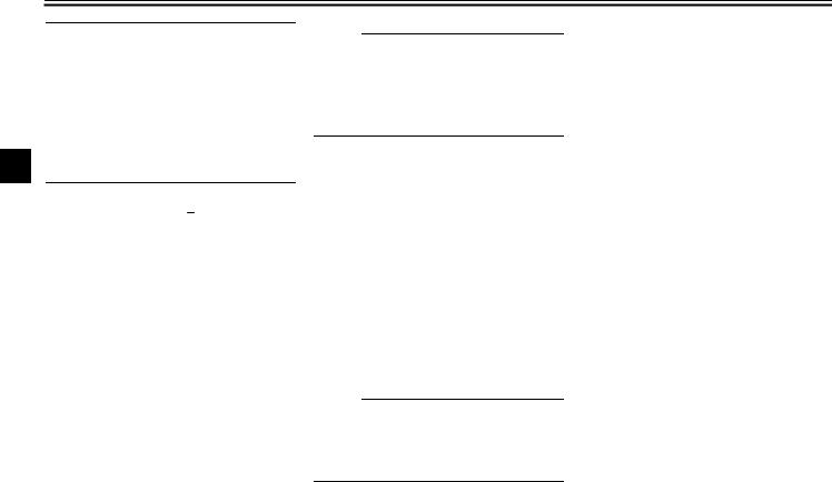
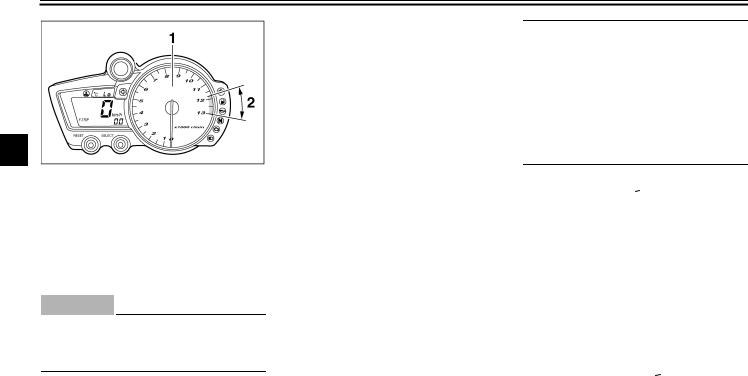
1.Tachometer
2.Tachometer red zone
EAU00101
Tachometer
The electric tachometer allows the rider to monitor the engine speed and keep it within the ideal power range.
EC000003
CAUTION:
Do not operate the engine in the tachometer red zone.
Red zone: 11,750 r/min and above
EAU00109
Anti-theft alarm (optional)
This motorcycle can be equipped with an optional anti-theft alarm by a Yamaha dealer. Contact a Yamaha dealer for more information.
1.Pass switch “PASS”
2.Dimmer switch “ /
/  ”
”
3.Turn signal switch “  /
/  ”
”
4.Horn switch “  ”
”
EAU00118
Handlebar switches
EAU04553
Pass switch “PASS”
Press this switch to flash the headlights.
EAU03888
Dimmer switch “ /
/  ”
”
Set this switch to “ ” for the high beam and to “
  ” for the low beam.
3-11

INSTRUMENT AND CONTROL FUNCTIONS
EAU03889
Turn signal switch “  /
/  ”
”
To signal a right-hand turn, push this switch to “  ”. To signal a left-hand turn, push this switch to “
  ”. When released, the switch returns to the center position. To cancel the turn signal lights, push the switch in after it has returned to the center position.
EAU00129
Horn switch “  ”
”
Press this switch to sound the horn.
1.Engine stop switch “  /
/  ”
”
2.Light switch “  /
/  /
/  ”
”
3.Start switch “  ”
”
EAU03890
Engine stop switch “  /
/  ”
”
Set this switch to “  ” before starting the engine. Set this switch to “
  ” to stop the engine in case of an emergency, such as when the motorcycle overturns or when the throttle cable is stuck.
EAU04557
Light switch “  /
/  /
/  ”
”
EAU00143
Start switch “  ”
”
Push this switch to crank the engine with the starter.
EC000005
CAUTION: |
|
_ |
|
See page 5-1 for starting instruc- |
|
tions prior to starting the engine. |
3 |
_ |
Set this switch to “  ” to turn on the auxiliary lights, meter lighting, taillight and license plate light. Set the switch to “
  ” to turn on the headlights also. Set the switch to “
  ” to turn off all the lights.
3-12

INSTRUMENT AND CONTROL FUNCTIONS
3
1. Clutch lever
EAU00152
Clutch lever
The clutch lever is located at the left handlebar grip. To disengage the clutch, pull the lever toward the handlebar grip. To engage the clutch, release the lever. The lever should be pulled rapidly and released slowly for smooth clutch operation.
The clutch lever is equipped with a clutch switch, which is part of the ignition circuit cut-off system. (See page 3-26 for an explanation of the ignition circuit cut-off system.)
1. Shift pedal
EAU00157
Shift pedal
The shift pedal is located on the left side of the engine and is used in combination with the clutch lever when shifting the gears of the 6-speed con- stant-mesh transmission equipped on this motorcycle.
1.Brake lever
2.Brake lever position adjusting dial
3.Arrow mark
a.Distance between brake lever and handlebar grip
EAU00161
Brake lever
The brake lever is located at the right handlebar grip. To apply the front brake, pull the lever toward the handlebar grip. The brake lever is equipped with a position adjusting dial. To adjust the distance between the brake lever and the handlebar grip, turn the adjusting dial while holding the lever pushed away from the handlebar grip. Make sure that the appropriate setting on the adjusting dial is aligned with the arrow mark on the brake lever.
3-13

INSTRUMENT AND CONTROL FUNCTIONS
1. Brake pedal
EAU00162
Brake pedal
The brake pedal is on the right side of the motorcycle. To apply the rear brake, press down on the brake pedal.
1.Fuel tank cap lock cover
2.Unlock.
EAU04068
Fuel tank cap
To open the fuel tank cap
Open the fuel tank cap lock cover, insert the key into the lock, and then turn it 1/4 turn clockwise. The lock will be released and the fuel tank cap can be opened.
To close the fuel tank cap
1.Push the fuel tank cap into position with the key inserted in the lock.
2.Remove the key, and then close the lock cover.
NOTE:
_
The fuel tank cap cannot be closed unless the key is in the lock. In addition, the key cannot be removed if the cap is not properly closed and locked.
_
EWA00025
 WARNING
_
Make sure that the fuel tank cap is 3 properly closed before riding.
_
3-14

INSTRUMENT AND CONTROL FUNCTIONS
3
1.Fuel tank filler tube
2.Fuel level
EAU03753
Fuel
Make sure that there is sufficient fuel in the tank. Fill the fuel tank to the bottom of the filler tube as shown.
EW000130
 WARNING
●Do not overfill the fuel tank, otherwise it may overflow when the fuel warms up and expands.
●Avoid spilling fuel on the hot engine.
EAU00185
CAUTION:
Immediately wipe off spilled fuel with a clean, dry, soft cloth, since fuel may deteriorate painted surfaces or plastic parts.
EAU04518
Recommended fuel: PREMIUM UNLEADED GASOLINE ONLY
Fuel tank capacity: Total amount:
17 L
Amount remaining when the fuel level warning light comes on:
3.3 L
ECA00104
CAUTION:
Use only unleaded gasoline. The use of leaded gasoline will cause severe damage to internal engine parts, such as the valves and piston rings, as well as to the exhaust system.
Your Yamaha engine has been designed to use regular unleaded gasoline with a research octane number of 95 or higher. If knocking (or pinging) occurs, use a gasoline of a different brand or premium unleaded fuel. Use of unleaded fuel will extend spark plug life and reduce maintenance costs.
3-15
Loading...