


2011
q Read this manual carefully before operating this vehicle.
OWNER’S SERVICE MANUAL
YZ450FA
LIT-11626-24-22 |
33D-28199-11 |
Q Read this manual carefully before operating this vehicle.This manual should stay with this vehicle if it is sold.

YZ450FA
OWNER'S SERVICE MANUAL
©2010 by Yamaha Motor Corporation, U.S.A. 1st Edition, May 2010
All rights reserved.
Any reprinting or unauthorized use without the written permission of Yamaha Motor Corporation, U.S.A. is expressly prohibited.
Printed in Japan
P/N. LIT-11626-24-22
INTRODUCTION
Congratulations on your purchase of a Yamaha YZ series. This model is the culmination of Yamaha's vast experience in the production of pacesetting racing machines. It represents the highest grade of craftsmanship and reliability that have made Yamaha a leader.
This manual explains operation, inspection, basic maintenance and tuning of your machine. If you have any questions about this manual or your machine, please contact your Yamaha dealer.
Yamaha continually seeks advancements in product design and quality. Therefore, while this manual contains the most current product information available at the time of printing, there may be minor discrepancies between your machine and this manual. If you have any questions concerning this manual, please consult your Yamaha dealer.
PLEASE READ THIS MANUAL CAREFULLY AND COMPLETELY BEFORE OPERATING THIS MACHINE. DO NOT ATTEMPT TO OPERATE THIS MACHINE UNTIL YOU HAVE ATTAINED A SATISFACTORY KNOWLEDGE OF ITS CONTROLS AND OPERATING FEATURES AND UNTIL YOU HAVE BEEN TRAINED IN SAFE AND PROPER RIDING TECHNIQUES. REGULAR INSPECTIONS AND CAREFUL MAINTENANCE, ALONG WITH GOOD RIDING SKILLS, WILL ENSURE THAT YOU SAFETY ENJOY THE CAPABILITIES AND THE RELIABILITY OF THIS MACHINE.
IMPORTANT MANUAL INFORMATION
Particularly important information is distinguished in this manual by the following notations.
This is the safety alert symbol. It is used to alert you to potential personal injury hazards. Obey all safety messages that follow this symbol to avoid possible injury or death.
A WARNING indicates a hazardous situation which, if not avoided, could result in death or serious injury.
A NOTICE indicates special precautions that must be taken to avoid damage to the vehicle or other property.
A TIP provides key information to make procedures easier or clearer.

SAFETY INFORMATION
THIS MACHINE IS DESIGNED STRICTLY FOR COMPETITION USE, ONLY ON A CLOSED COURSE. It is illegal for this machine to be operated on any public street, road, or highway. Off-road use on public lands may also be illegal. Please check local regulations before riding.
•THIS MACHINE IS TO BE OPERATED BY AN EXPERIENCED RIDER ONLY.
Do not attempt to operate this machine at maximum power until you are totally familiar with its characteristics.
•THIS MACHINE IS DESIGNED TO BE RIDDEN BY THE OPERATOR ONLY.
Do not carry passengers on this machine.
•ALWAYS WEAR PROTECTIVE APPAREL. When operating this machine, always wear an approved helmet with goggles or a face shield. Also wear heavy boots, gloves, and protective clothing. Always wear proper fitting clothing that will not be caught in any of the moving parts or controls of the machine.
•ALWAYS MAINTAIN YOUR MACHINE IN PROPER WORKING ORDER.
For safety and reliability, the machine must be properly maintained. Always perform the preoperation checks indicated in this manual.
Correcting a mechanical problem before you ride may prevent an accident.
•GASOLINE IS HIGHLY FLAMMABLE. Always turn off the engine while refueling. Take care to not spill any gasoline on the engine or exhaust system. Never refuel in the vicinity of an open flame, or while smoking.
•GASOLINE CAN CAUSE INJURY.
If you should swallow some gasoline, inhale excess gasoline vapors, or allow any gasoline to get into your eyes, contact a doctor immediately. If any gasoline spills onto your skin or clothing, immediately wash skin areas with soap and water, and change your clothes.
•ONLY OPERATE THE MACHINE IN AN AREA WITH ADEQUATE VENTILATION. Never start the engine or let it run for any length of time in an enclosed area. Exhaust fumes are poisonous. These fumes contain carbon monoxide, which by itself is odorless and colorless. Carbon monoxide is a dangerous gas which can cause unconsciousness or can be lethal.
•PARK THE MACHINE CAREFULLY; TURN OFF THE ENGINE.
Always turn off the engine if you are going to leave the machine. Do not park the machine on a slope or soft ground as it may fall over.
•THE ENGINE, EXHAUST PIPE, MUFFLER, AND OIL TANK WILL BE VERY HOT AFTER THE ENGINE HAS BEEN RUN.
Be careful not to touch them or to allow any clothing item to contact them during inspection or repair.
•PROPERLY SECURE THE MACHINE BEFORE TRANSPORTING IT.
For safety, drain the gasoline from the fuel tank before transporting the vehicle.

YAMAHA MOTOR CORPORATION, U.S.A. YZ MOTORCYCLE LIMITED WARRANTY
HOW TO USE THIS MANUAL
FINDING THE REQUIRED PAGE
1.This manual consists of eight chapters; "General Information", "Specifications", "Regular inspection and adjustments", "Engine", "Chassis", "Fuel system", "Electrical" and "Tuning".
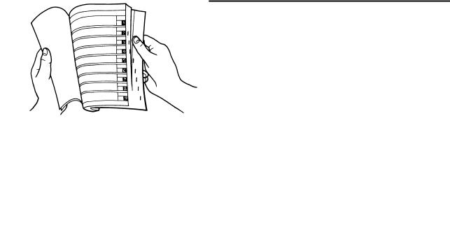
2.The table of contents is at the beginning of the manual. Look over the general layout of the book before finding then required chapter and item.
Bend the book at its edge, as shown, to find the required fore edge symbol mark and go to a page for required item and description.
MANUAL FORMAT
All of the procedures in this manual are organized in a sequential, step-by-step format. The information has been complied to provide the mechanic with an easy to read, handy reference that contains comprehensive explanations of all disassembly, repair, assembly, and inspection operations.
In this revised format, the condition of a faulty component will precede an arrow symbol and the course of action required will follow the symbol, e.g.,
•Bearings
Pitting/damage → Replace.
HOW TO READ DESCRIPTIONS
To help identify parts and clarify procedure steps, there are exploded diagrams at the start of each removal and disassembly section.
1.An easy-to-see exploded diagram "1" is provided for removal and disassembly jobs.
2.Numbers "2" are given in the order of the jobs in the exploded diagram. A number that is enclosed by a circle indicates a disassembly step.
3.An explanation of jobs and notes is presented in an easy-to-read way by the use of symbol marks "3". The meanings of the symbol marks are given on the next page.
4.A job instruction chart "4" accompanies the exploded diagram, providing the order of jobs, names of parts, notes in jobs, etc.
5.For jobs requiring more information, the step-by-step format supplements "5" are given in addition to the exploded diagram and job instruction chart.
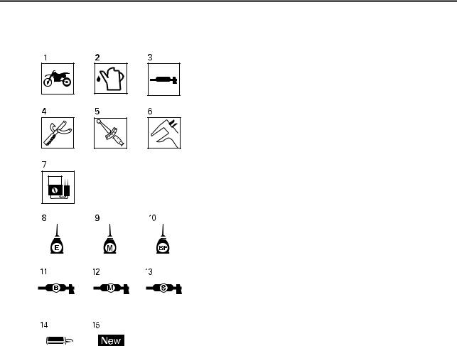
ILLUSTRATED SYMBOLS (Refer to the illustration)
Illustrated symbols "1" to "7" are used to identify the specifications appearing in the text.
1.With engine mounted
2.Filling fluid
3.Lubricant
4.Special tool
5.Tightening
6.Specified value, Service limit
7.Resistance (Ω), Voltage (V), Electric current (A)
Illustrated symbols "8" to "13" in the exploded diagrams indicate grade of lubricant and location of lubrication point.
8.Apply engine oil
9.Apply molybdenum disulfide oil
10.Apply brake fluid
11.Apply lightweight lithium-soap base grease
12.Apply molybdenum disulfide grease
13.Apply silicone grease
Illustrated symbols "14" to "15" in the exploded diagrams indicate where to apply a locking agent and where to install new parts.
14.Apply locking agent (LOCTITE®)
15.Use new one

MEMO
TABLE OF CONTENTS
GENERAL INFORMATION |
1 |
|
|
|
|
|
|
|
SPECIFICATIONS |
2 |
|
|
|
|
|
|
|
REGULAR INSPECTION AND |
3 |
|
ADJUSTMENTS |
||
|
||
|
|
|
|
|
|
ENGINE |
4 |
|
|
|
|
|
|
|
CHASSIS |
5 |
|
|
|
|
|
|
|
FUEL SYSTEM |
6 |
|
|
|
|
|
|
|
ELECTRICAL |
7 |
|
|
|
|
|
|
|
TUNING |
8 |
|
|
|

CONTENTS
CHAPTER 1
GENERAL INFORMATION
LOCATION OF IMPORTANT LABELS |
..... 1-1 |
DESCRIPTION ........................................... |
1-2 |
CONSUMER INFORMATION .................... |
1-3 |
FEATURES ................................................ |
1-4 |
INCLUDED PARTS.................................... |
1-6 |
IMPORTANT INFORMATION.................... |
1-8 |
HANDLING THE ELECTRONIC |
|
PARTS ..................................................... |
1-10 |
CHECKING OF CONNECTION ............... |
1-10 |
SPECIAL TOOLS..................................... |
1-12 |
CONTROL FUNCTIONS.......................... |
1-17 |
STARTING AND BREAK-IN.................... |
1-19 |
TORQUE-CHECK POINTS...................... |
1-21 |
CLEANING AND STORAGE ................... |
1-22 |
CHAPTER 2
SPECIFICATIONS
GENERAL SPECIFICATIONS................... |
2-1 |
MAINTENANCE SPECIFICATIONS.......... |
2-4 |
TIGHTENING TORQUES......................... |
2-13 |
LUBRICATION DIAGRAMS .................... |
2-21 |
CABLE ROUTING DIAGRAM.................. |
2-23 |

CHAPTER 3
REGULAR INSPECTION AND
ADJUSTMENTS
MAINTENANCE INTERVALS.................... |
3-1 |
PRE-OPERATION INSPECTION AND |
|
MAINTENANCE ......................................... |
3-6 |
ENGINE...................................................... |
3-7 |
CHASSIS.................................................. |
3-20 |
ELECTRICAL........................................... |
3-37 |
TROUBLESHOOTING ............................. |
3-39 |
CHAPTER 4
ENGINE
SEAT AND SIDE COVERS........................ |
4-1 |
EXHAUST PIPE AND SILENCER ............. |
4-3 |
RADIATOR................................................. |
4-8 |
CAMSHAFTS ........................................... |
4-12 |
CYLINDER HEAD .................................... |
4-19 |
VALVES AND VALVE SPRINGS ............ |
4-23 |
CYLINDER AND PISTON ........................ |
4-30 |
CLUTCH................................................... |
4-35 |
OIL FILTER ELEMENT AND |
|
WATER PUMP ......................................... |
4-41 |
BALANCER ............................................. |
4-47 |
OIL PUMP ................................................ |
4-51 |
KICK SHAFT AND SHIFT SHAFT........... |
4-55 |
AC MAGNETO ......................................... |
4-62 |
ENGINE REMOVAL................................. |
4-65 |
CRANKCASE AND CRANKSHAFT........ |
4-71 |
TRANSMISSION, SHIFT CAM AND |
|
SHIFT FORK ............................................ |
4-79 |

CHAPTER 5
CHASSIS
FRONT WHEEL AND REAR WHEEL |
....... 5-2 |
FRONT BRAKE AND REAR BRAKE........ |
5-9 |
FRONT FORK .......................................... |
5-23 |
HANDLEBAR........................................... |
5-36 |
STEERING ............................................... |
5-42 |
SWINGARM ............................................. |
5-47 |
REAR SHOCK ABSORBER.................... |
5-54 |
CHAPTER 6
FUEL SYSTEM
FUEL TANK ............................................... |
6-2 |
THROTTLE BODY ..................................... |
6-6 |
CHAPTER 7
ELECTRICAL
ELECTRICAL COMPONENTS AND |
|
WIRING DIAGRAM .................................... |
7-1 |
IGNITION SYSTEM.................................... |
7-4 |
THROTTLE POSITION |
|
SENSOR SYSTEM..................................... |
7-8 |
FUEL INJECTION SYSTEM .................... |
7-11 |
FUEL PUMP SYSTEM ............................. |
7-44 |
ELECTRICAL COMPONENTS ................ |
7-45 |
CHAPTER 8
TUNING
CHASSIS.................................................... |
8-1 |
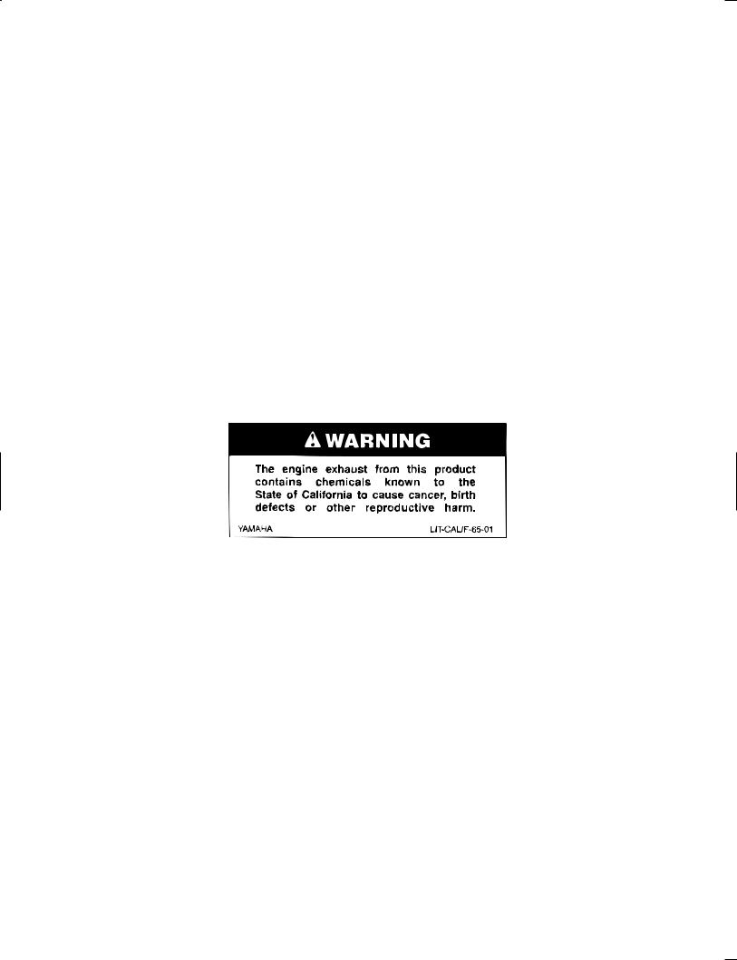
LOCATION OF IMPORTANT LABELS
GENERAL INFORMATION
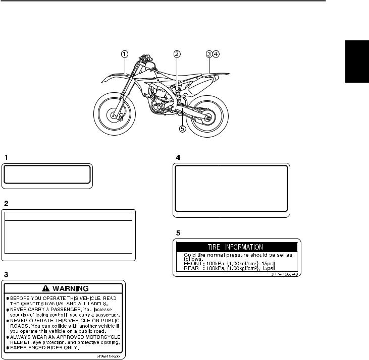
LOCATION OF IMPORTANT LABELS
Please read the following important labels carefully before operating this vehicle.
1
Premium unleaded gasoline only.
3FB-2415E-02
 WARNING
This unit contains high pressure nitrogen gas. Mishandling can cause explosion.
 Read owner’s manual for instructions.
  Do not incinerate, puncture or open.
4AA-22259-80
For use only on a closed course in sanctioned competition.
This motorcycle does not meet EPA noise and emissions standards and is not for general off-road recreational riding.
17D-2812P-00
1-1
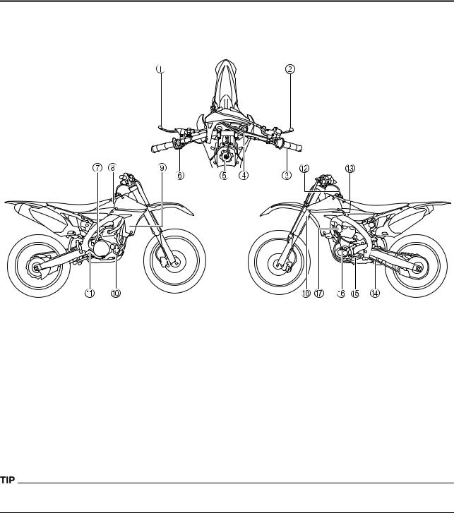
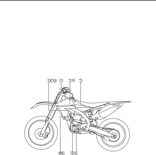
DESCRIPTION
DESCRIPTION
1. |
Clutch lever |
10. |
Coolant drain bolt |
2. |
Front brake lever |
11. |
Rear brake pedal |
3. |
Throttle grip |
12. |
Valve joint |
4. |
Radiator cap |
13. |
Air cleaner |
5. |
Fuel tank cap |
14. |
Drive chain |
6. |
Engine stop switch |
15. |
Shift pedal |
7. |
Kickstarter crank |
16. |
Oil level check window |
8. |
Fuel tank |
17. |
Starter knob/idle screw |
9. |
Radiator |
18. |
Front fork |
•The machine you have purchased may differ slightly from those shown in the following.
•Designs and specifications are subject to change without notice.
1-2
CONSUMER INFORMATION
CONSUMER INFORMATION
There are two significant reasons for knowing the serial number of your machine:
1.When ordering parts, you can give the number to your Yamaha dealer for positive identification of the model you own.
2.If your machine is stolen, the authorities will need the number to search for and identify your machine.
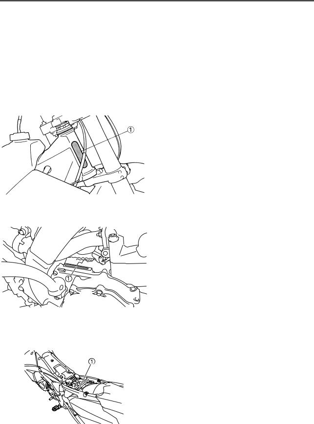
VEHICLE IDENTIFICATION NUMBER
The vehicle identification number "1" is stamped on the right of the steering head pipe.
ENGINE SERIAL NUMBER
The engine serial number "1" is stamped into the elevated part of the right-side of the engine.
MODEL LABEL
The model label "1" is affixed to the frame under the rider's seat. This information will be needed to order spare parts.
1-3
FEATURES
FEATURES
OUTLINE OF THE FI SYSTEM
The main function of a fuel supply system is to provide fuel to the combustion chamber at the optimum air-fuel ratio in accordance with the engine operating conditions and the atmospheric temperature.Inthe conventional carburetor system, the air-fuel ratio of the mixture that is supplied to the combustionchamber is created by the volume of the intake air and the fuel that is metered by the jet used in the respective carburetor.
Despite the same volume of intake air, the fuel volume requirement varies by the engine operating conditions,such as acceleration, deceleration, or operating under a heavy load.Carburetors that meter the fuel through the use of jets have been provided with various auxiliary devices, so that an optimum air fuel ratio can be achieved to accommodate the constant changes in the operating conditions of the engine.
This model has adopted an electronically controlled fuel injection (FI) system, in place of the conventional carburetor system.This system can achieve an optimum air-fuel ratio required by the engine at all times by using a microprocessor that regulates the fuel injection volume according to the engine operating conditions detected by various sensors.
1. |
Fuel injector |
7. |
Atmospheric pressure sensor |
2. |
Throttle position sensor |
8. |
Crankshaft position sensor |
3. |
Intake air pressure sensor |
9. |
Coolant temperature sensor |
4. |
ECU |
10. |
Ignition coil |
5. |
Fuel pump |
11. |
Condenser |
6. |
Intake air temperature sensor |
|
|
1-4
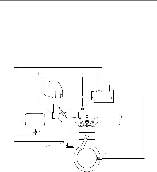
FEATURES
FI SYSTEM
The fuel pump delivers fuel to the fuel injector via the fuel filter. The pressure regulator maintains the fuel pressure that is applied to the fuel injector at only 324 kPa (3.24 kgf/cm ² , 47.0 psi). Accordingly,when the energizing signal from the ECU energizes the fuel injector, the fuel passage opens, causing the fuel to be injected into the intake manifold only during the time the passage remains open.
Therefore, the longer the length of time the fuel injector is energized (injection duration), the greater the volume of fuel that is supplied. Conversely, the shorter the length of time the fuel injector is energized(injection duration), the lesser the volume of fuel that is supplied.
The injection duration and the injection timing are controlled by the ECU. Signals that are input from the throttle position sensor, coolant temperature sensor, atmospheric pressure sensor, lean angle sensor, crankshaft position sensor, intake air pressure sensor and intake air temperature sensor enable the ECU to determine the injection duration. The injection timing is determined through the signals from the rankshaft position sensor. As a result, the volume of fuel that is required by the engine can be supplied at all times in accordance with the driving conditions.
|
|
C |
|
|
1 |
11 |
A |
5 |
|
|
|
|
|
2 |
10 |
|
|
|
B |
|
9 |
|
|
8 |
7 |
|
|
|
4 |
3 |
6 |
1. |
Fuel pump |
11. |
Atmospheric pressure sensor |
2. |
Fuel injector |
|
|
3. |
ECU |
A. |
Fuel system |
4. |
Throttle position sensor |
B. |
Intake system |
5. |
Coolant temperature sensor |
C. |
Control system |
6.Crankshaft position sensor
7.Intake air pressure sensor
8.Throttle body
9.Intake air temperature sensor
10.Air filter case
1-5
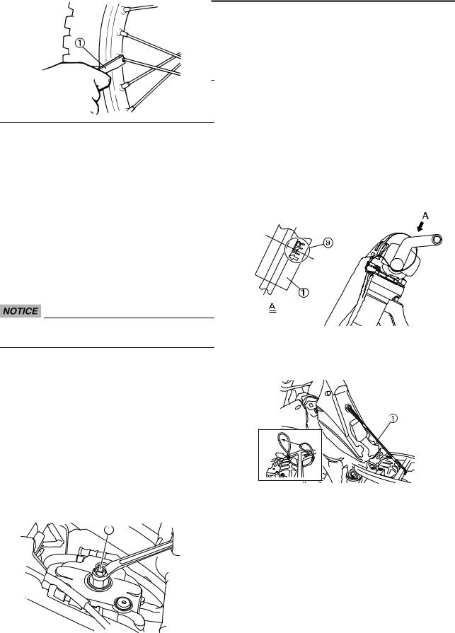
INCLUDED PARTS
INCLUDED PARTS
DETACHABLE SIDESTAND
This sidestand "1" is used to support only the machine when standing or transporting it.
•Never apply additional force to the sidestand.
•Remove this sidestand before starting out.
VALVE JOINT
This valve joint "1" prevents fuel from flowing out and is installed to the fuel tank breather hose.
In this installation, make sure the arrow faces the fuel tank and also downward.
SPARK PLUG WRENCH
This spark plug wrench "1" is used to remove and install the spark plug.
NIPPLE WRENCH
This nipple wrench "1" is used to tighten the spoke.
HANDLEBAR PROTECTOR
Install the handlebar protector "1" so that the mark "a" face forward.
FUEL TANK HOLDING CABLE
The fuel tank holding cable "1" is used to support the fuel tank during maintenance.
1-6
INCLUDED PARTS
FUEL HOSE JOINT COVER
The fuel hose joint covers "1" are used to prevent mud, dust, and other foreign material from entering the fuel pump when the fuel hose is disconnected.
COUPLER FOR CONNECTING OPTIONAL PART
This coupler "1" is used for connection to an optional Power Tuner and so on.
When no optional parts, etc. are connected, connect the connection terminal to the original coupler "2".
Before removing the coupler, thoroughly wipe off any mud or water stuck to it.
Part name |
Part number |
|
|
GYTR Power Tuner |
33D-H59C0-V0-00 |
The GYTR Power Tuner is optional.
1-7
IMPORTANT INFORMATION
IMPORTANT INFORMATION
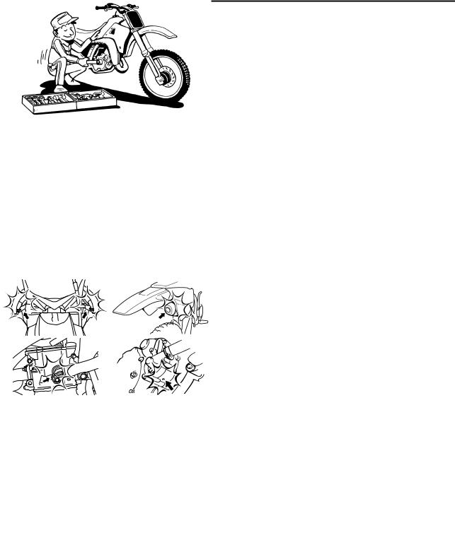
PREPARATION FOR REMOVAL AND DISASSEMBLY
1.Remove all dirt, mud, dust, and foreign material before removal and disassembly.
•When washing the machine with high pressured water, cover the parts follows.
Air duct
Silencer exhaust port
Drain hole on the cylinder head (right side) Water pump housing hole at the bottom
2.Use proper tools and cleaning equipment. Refer to "SPECIAL TOOLS" section.
3.When disassembling the machine, keep mated parts together. They include gears, cylinders, pistons, and other mated parts that have been "mated" through normal wear. Mated parts must be reused as an assembly or replaced.
4.During the machine disassembly, clean all parts and place them in trays in the order of disassembly. This will speed up assembly time and help assure that all parts are correctly reinstalled.
5. Keep away from fire.
ALL REPLACEMENT PARTS
1.We recommend to use Yamaha genuine parts for all replacements. Use oil and/or grease recommended by Yamaha for assembly and adjustment.
GASKETS, OIL SEALS AND O-RINGS
1.All gaskets, oil seals, and O-rings should be replaced when an engine is overhauled. All gasket surfaces, oil seal lips, and O-rings must be cleaned.
2.Properly oil all mating parts and bearings during reassembly. Apply grease to the oil seal lips.
1-8
IMPORTANT INFORMATION
LOCK WASHERS/PLATES AND COTTER PINS
1.All lock washers/plates "1" and cotter pins must be replaced when they are removed. Lock tab(s) should be bent along the bolt or nut flat(s) after the bolt or nut has been properly tightened.
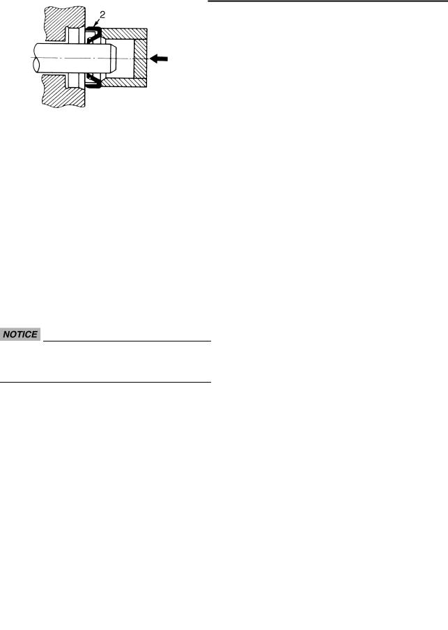
BEARINGS AND OIL SEALS
1.Install the bearing(s) "1" and oil seal(s) "2" with their manufacturer's marks or numbers facing outward. (In other words, the stamped letters must be on the side exposed to view.) When installing oil seal(s), apply a light coating of lightweight lithium base grease to the seal lip(s). Oil the bearings liberally when installing.
Do not use compressed air to spin the bearings dry. This causes damage to the bearing surfaces.
CIRCLIPS
1.All circlips should be inspected carefully before reassembly. Always replace piston pin clips after one use. Replace distorted circlips. When installing a circlip "1", make sure that the sharp-edged corner "2" is positioned opposite to the thrust "3" it receives. See the sectional view.
1-9

HANDLING THE ELECTRONIC PARTS
HANDLING THE ELECTRONIC PARTS
Electronic parts are very sensitive. Handle with care and do not give impact.
•Mankind has static electricity. It`s voltage is very high and electronic parts are very sensitive.
•It is possible that inner small components of electronic parts are destroyed by static electricity.
•Do not touch and do not make them dirty.
CHECKING OF CONNECTION
Check the leads, couplers, and connectors for stains, rust, moisture, etc.
1.Disconnect:
•Lead
•Coupler
•Connector
2.Check:
•Lead
•Coupler
•Connector
Moisture → Dry with an air blower. Rust/stains → Connect and disconnect several times.
3.Check:
•All connections
Loose connection → Connect properly.
If the pin "1" on the terminal is flattened, bend it up.
If the contact seems not good, pull the terminal by hand and check its condition.
4.Connect:
•Lead
•Coupler
•Connector
Make sure all connections are tight.
1-10
CHECKING OF CONNECTION
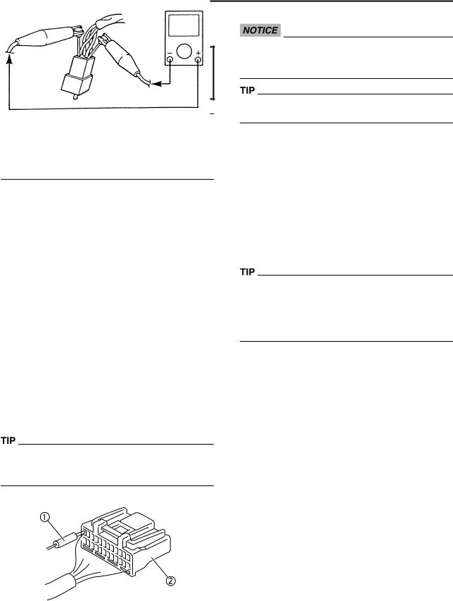
5.Check:
•Continuity
(with the pocket tester)
Pocket tester: 90890-03112
Analog pocket tester: YU-03112-C
•If there is no continuity, clean the terminals.
•When checking the wire harness, perform steps (1) to (5).
•As a quick remedy, use a contact revitalizer available at most part stores.
REMOVING THE QUICK FASTENER
Do not push the center pin with too much force. Otherwise, the center pin could be damaged.
To remove a quick fastener, push the center pin in with a screwdriver, then pull the fastener out.
INSTALLING THE QUICK FASTENER
To install a quick fastener, push its center pin "a" back so that it protrudes from the fastener head, then insert the fastener and push the protruding pin in until it is flush with the fastener head.
When you check the voltage or electrical continuity, insert the measuring probe from back side as you can insert from back side.
1.Probe
2.Coupler
1-11

SPECIAL TOOLS
SPECIAL TOOLS
The proper special tools are necessary for complete and accurate tune-up and assembly. Using the correct special tool will help prevent damage caused by the use of improper tools or improvised techniques. The shape and part number used for the special tool differ by country, so two types are provided. Refer to the list provided to avoid errors when placing an order.
•For U.S.A. and Canada, use part number starting with "YM-", "YU-" or "ACC-".
•For others, use part number starting with "90890-".
Tool name/Part number |
How to use |
Illustration |
|
|
|
Dial gauge and stand |
These tools are used to check |
|
YU-3097, 90890-01252 |
each part for runout or bend. |
|
Stand |
|
|
YU-1256 |
|
|
|
|
|
Crankshaft installing tool |
These tools are used to install |
|
Crankshaft installing pot |
the crankshaft. |
|
YU-90050, 90890-01274 |
|
|
Crankshaft installing bolt |
|
|
YU-90050, 90890-01275 |
|
|
Spacer (crankshaft installer) |
|
|
YM-91044, 90890-04081 |
|
|
Adapter (M12) |
|
|
YU-90063, 90890-01278 |
|
|
|
|
|
Piston pin puller set |
This tool is used to remove |
|
YU-1304, 90890-01304 |
the piston pin. |
|
|
|
|
Radiator cap tester |
These tools are used for |
|
YU-24460-01, 90890-01325 |
checking the cooling system. |
|
Radiator cap tester adapter |
|
|
YU-33984, 90890-01352 |
|
|
|
|
|
1-12
|
|
SPECIAL TOOLS |
Tool name/Part number |
How to use |
Illustration |
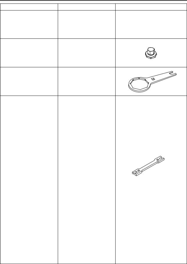
Steering nut wrench |
This tool is used when tighten |
|
YU-33975, 90890-01403 |
the steering ring nut to speci- |
|
|
fication. |
|
Cap bolt wrench |
This tool is used to loosen or |
|
YM-01500, 90890-01500 |
tighten the base valve. |
|
Cap bolt ring wrench |
This tool is used to loosen or |
|
YM-01501, 90890-01501 |
tighten the damper assembly. |
|
Fork seal driver |
This tool is used when install |
|
YM-A0948, 90890-01502 |
the fork oil seal. |
|
Spoke nipple wrench |
This tool is used to tighten the |
YM-01521, 90890-01521 |
spoke. |
|
|
Pocket tester |
Use this tool to inspect the |
YU-03112-C, 90890-03112 |
coil resistance, output voltage |
|
and amperage. |
|
|
Timing light |
This tool is necessary for |
YM-33277-A, 90890-03141 |
checking ignition timing. |
1-13

|
|
SPECIAL TOOLS |
Tool name/Part number |
How to use |
Illustration |
Pressure gauge. |
This tool is used to measure |
|
YU-03153, 90890-03153 |
the fuel pressure. |
|
FI diagnostic tool |
This tool is used to check the |
|
YU-03182, 90890-03182 |
fault codes and diagnose any |
|
|
problems. |
|
Fuel pressure adapter |
This tool is used to attach the |
|
YM-03186, 90890-03186 |
pressure gauge. |
|
Test harness S-pressure sen- |
This tool is connected be- |
|
sor (3P) |
tween the intake air pressure |
|
YU-03207, 90890-03207 |
sensor and the wire harness |
|
|
and is used to measure the |
|
|
voltage. |
|
Test harness-speed sensor |
This tool is connected be- |
|
(3P) |
tween the throttle position |
|
YU-03208, 90890-03208 |
sensor and the wire harness |
|
|
and is used to measure the |
|
|
voltage. |
|
FI diagnostic tool sub-lead |
This tool is used to connect |
|
YU-03212, 90890-03212 |
the FI diagnostic tool to a bat- |
|
|
tery. |
|
Valve guide remover & in- |
This tool is needed to remove |
|
staller set |
and install the valve guide. |
|
90890-04016 |
|
|
Valve spring compressor |
This tool is needed to remove |
|
YM-4019, 90890-04019 |
and install the valve assem- |
|
|
blies. |
|
1-14

|
|
SPECIAL TOOLS |
|
|
|
|
|
|
Tool name/Part number |
How to use |
Illustration |
|
|
|
Clutch holding tool |
This tool is used to hold the |
|
YM-91042, 90890-04086 |
clutch when removing or in- |
|
|
stalling the clutch boss secur- |
|
|
ing nut. |
|
Valve guide remover |
This tool is needed to remove |
5.5 mm (0.22 in) |
and install the valve guide. |
YM-01122 |
|
|
|
Valve guide installer |
This tool is needed to install |
5.5 mm (0.22 in) |
the valve guide. |
YM-04015 |
|
|
|
Valve guide reamer |
This tool is needed to rebore |
5.5 mm (0.22 in) |
the new valve guide. |
YM-01196 |
|
|
|
Valve spring compressor at- |
This tool is needed to remove |
tachment |
and install the valve assem- |
YM-04108, 90890-04108 |
blies. |
|
|
Rotor puller |
This tool is used to remove |
YM-04151, 90890-04151 |
the flywheel magneto. |
|
|
Crankcase separating tool |
These tool is used to remove |
YU-A9642 |
the crankshaft from either |
90890-04152 |
case. |
1-15

|
|
SPECIAL TOOLS |
|
|
|
|
|
|
Tool name/Part number |
How to use |
Illustration |
|
|
|
Dynamic spark tester |
This instrument is necessary |
|
YM-34487 |
for checking the ignition sys- |
|
Ignition checker |
tem components. |
|
90890-06754 |
|
|
|
|
|
Digital tachometer |
This tool is needed for ob- |
|
YU-39951-B, 90890-06760 |
serving engine rpm. |
|
|
|
|
YAMAHA Bond No. 1215 |
This sealant (Bond) is used |
|
(ThreeBond® No. 1215) |
for crankcase mating surface, |
|
90890-85505 |
etc. |
|
|
|
|
1-16
 Loading...